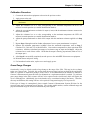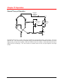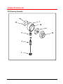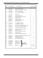
1
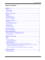
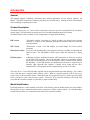
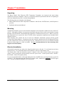
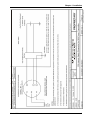
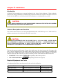
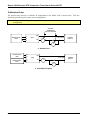
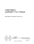
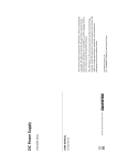
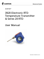
BARTON®
3920 Electronic RTD
Temperature Transmitter
& Series 20 RTD
User Manual
Manual No. 55165001, Rev. 01
SAFETY/CUSTOMER SERVICE NOTICE
The warranty applicable to this product is stated at the beginning of this manual.
Should any problem arise after-delivery, please contact the Cameron’s Measurement Systems HelpDesk at 1877-805-7226 or the Customer Service department during normal business hours at (403) 291-4814.
Before installing the instrument, become familiar with the installation instructions.
Also, be aware of the following important notice that appears in the manual:
•
WARNING notes indicate the presence of a hazard that can cause severe personal injury, death or
substantial property damage if the warning is ignored.
•
CAUTION notes indicate the presence of a hazard, which will or can cause minor personal injury or
property damage if the warning is ignored.
© 2007 Cameron International Corporation (“Cameron”). All information contained in this
publication is confidential and proprietary property of Cameron. Any reproduction or use of
these instructions, drawings, or photographs without the express written permission of an
officer of Cameron is forbidden.
All Rights Reserved.
Printed in the United States of America.
Manual No. 55165001, Rev. 01
March 2007
Table of Contents
TABLE OF CONTENTS
INTRODUCTION........................................................................................................................................... 1
General...................................................................................................................................................... 1
Product Description ................................................................................................................................... 1
Model Identification.................................................................................................................................... 1
CHAPTER 1: INSTALLATION ..................................................................................................................... 3
Unpacking.................................................................................................................................................. 3
Mounting.................................................................................................................................................... 3
Electrical Installation.................................................................................................................................. 3
Intrinsically Safe Installation ...................................................................................................................... 4
Explosionproof Installation ........................................................................................................................ 4
CHAPTER 2: CALIBRATION....................................................................................................................... 7
Introduction................................................................................................................................................ 7
Controls Description and Location ............................................................................................................ 7
Required Equipment and Tools................................................................................................................. 7
Calibration Setup ....................................................................................................................................... 8
Calibration Procedure................................................................................................................................ 9
Gross Range Changes .............................................................................................................................. 9
CHAPTER 3: OPERATION ........................................................................................................................ 11
General Theory of Operation................................................................................................................... 11
CHAPTER 4: MAINTENANCE................................................................................................................... 13
Removal of EM-Module from Explosionproof Enclosures....................................................................... 13
Installation of EM Module in Explosionproof Housings ........................................................................... 13
Connector Cleaning................................................................................................................................. 13
CHAPTER 5: SPECIFICATIONS ............................................................................................................... 15
General.................................................................................................................................................... 15
Options .................................................................................................................................................... 18
Order Code (Model 3920) ....................................................................................................................... 19
3920 Housing Configurations.............................................................................................................. 21
Order Code (Series 20) ........................................................................................................................... 22
Outline Dimension Drawings ................................................................................................................... 23
3920 Integral Blind Transmitter & Series 20 RTD with Terminal Housing ....................................... 23
3920 Integral Indicating Transmitter (and Blind Transmitters or Series 20 with “GB” Option) ........ 24
3920 Pipe Mount Transmitter (Indicating or Blind)............................................................................ 25
3920 Remote Indicating Transmitter (and Blind Transmitters with “GB” Option) ............................ 26
CHAPTER 6: PARTS LIST......................................................................................................................... 27
3920 Housing Assembly.......................................................................................................................... 27
3920 Module Assembly ........................................................................................................................... 29
March 2007
i
Barton 3920 Electronic RTD Temperature Transmitter & Series 20 RTD
ii
March 2007
Introduction
General
This manual contains installation, operational and technical information for two separate products, the
Barton® 3920 RTD Temperature Transmitter and the Series 20 RTD Sensor. Read all sections of this manual
before installing or operating these units.
Product Description
The Model 3920 uses a 2 or 3-wire resistive temperature detector to provide a proportional 4-20 mA analog
current output. The 3920 boards are enclosed in an oval extruded aluminum protective housing.
The Barton Model 3920 is available in four configurations for application flexibility:
EM Version
“Electronics module” consisting of a circuit assembly (two printed circuit boards)
enclosed in a protective cast aluminum housing with external controls for span and
zero adjustments.
WL Version
“Wall-mount” version of the EM module; two metal flanges for wall or surface
mounting.
Hazardous Location
Two-piece cast aluminum alloy explosionproof enclosure (available in indicating and
blind versions). The EM module is held in place within the enclosure by a spring
clip.
RF Unit Option
Additional protection for Radio Frequency (RF) interference is offered as an option
on the EM or WL modules. This is not normally offered on a hazardous location
model since the aluminum shell of the Hazardous Location enclosure offers inherent
RF shielding. On the EM module, the standard input connector is replaced by an
alternate input connector that contains a printed circuit board and the filter.
Dimensionally, a RF equipped module is approximately 10 mm (3/8”) taller.
The Series 20 is a 3-wire RTD normally supplied with an integral hazardous location housing. It is a subset
of the 3920 and may be supplied with or without a 3920. When it is supplied with the 3920, it serves as a
remote sensor to the electronics module. When the Series 20 is supplied by itself, it is used to provide a RTD
sensor resistance to some other electronic system. The Series 20 is physically identical to the blind 3920
except that the electronics module is replaced by a simple terminal strip.
Model Identification
Each instrument has a label mounted on the back of the housing with the model number and serial number
that identifies its type, functional characteristics, parameters, and the options ordered. On 3920 Hazardous
Location models, there is a second label on the back of the electronics module.
March 2007
1
Barton 3920 Electronic RTD Temperature Transmitter & Series 20 RTD
2
March 2007
Chapter 1: Installation
Unpacking
The Barton Model 3920 Electronic RTD Temperature Transmitter was inspected and tested during
manufacture and prior to shipment. However, an inspection should be performed at the time of unpacking to
detect any damage that may have occurred during shipment.
The following items are included in each shipment:
•
Model 3920 Electronic RTD Temperature Transmitter and/or Series 20 RTD Sensor, with all options as
specified
•
Installation and Operation Manual
Mounting
Consideration should be given to ensure that the temperature of the electronics module does not exceed 85°C
(180°F). Although the modules do not generate measurable amounts of heat on their own, hazardous location
housings can trap heat that is absorbed through conduction or radiation from the process. Where excessively
high temperatures are expected, the Series 20 RTD, with an appropriate temperature-rated terminal block,
should be selected.
When mounting, also consider the ease of access for calibration, maintenance purposes and the regular
viewing of the optional display. In situations where this would be a problem, the Series 20 Remote RTD may
provide a solution since it has no parts that require access. When the Series 20 is used, it should be mounted
so that the cable length is as short as possible. It is not recommended that the interconnecting cable
length exceed 150 m (500 ft.).
Electrical Installation
All electrical connections are made to the integral terminal strip on the unit. To avoid transients and stray
electrical noises, it is recommended that twisted conductors with an overall shield be used.
The distance that a 3920 can transmit its signal is a function of the cable resistance and the power supply
voltage. Units are designed to operate directly from a DC power source. Connect power leads to +PS and –
PS terminals. Observe the proper polarity.
It is not recommended that the cable length linking the Series 20 RTD to the receiving electronics exceed 150
m (500 ft.). The interconnecting cable should be a twisted “triad” constructed of minimum 18 AWG copper
wire. The three conductors should have an overall shield.
March 2007
3
Barton 3920 Electronic RTD Temperature Transmitter & Series 20 RTD
Intrinsically Safe Installation
When installed as per drawing 3920-9000-0 (page 4) and local electrical code requirements, the 3920 is CSA
listed as Intrinsically Safe.
The Series 20, being CSA approved and a simple device, may be installed as Intrinsically Safe by protecting
the RTD with any appropriate CSA approved I.S. barrier. At an additional cost, Cameron will supply an
appropriate I.S. barrier.
An I.S. barrier is not required between a 3920 and a Series 20 remote RTD when the 3920 is protected by a
barrier.
Explosionproof Installation
When equipped with Hazardous Location housing, the cover is in place and installation is carried out as per
local code requirements. The entire assembly is CSA approved.
WARNING
SPRING-LOADED RTD PROBES AS USED ON SERIES 20 RTDs AND 3920 TEMPERATURE
TRANSMITTERS ARE EXPLOSIONPROOF ONLY WHEN INSTALLED IN A CAMERON-SUPPLIED
THERMOWELL. DE-ENERGIZE CIRCUITS OR OTHERWISE RENDER THE AREA SAFE BEFORE
REMOVING THE RTD FROM THE THERMOWELL.
4
March 2007
Chapter 1: Installation
March 2007
5
Barton 3920 Electronic RTD Temperature Transmitter & Series 20 RTD
6
March 2007
Chapter 2: Calibration
Introduction
All Model 3920 transmitters are accurately adjusted at the factory before shipment. Unless otherwise
specified, the factory calibration is performed using a decade resistance box in place of the RTD. Series 20
models and other RTDs are not factory checked for conformance, as no adjustments are possible.
CAUTION
DO NOT CHECK OR ADJUST ANY UNIT UNLESS PROPER TOOLS AND TEST SETUP WITH CURRENT
PROCEDURES ARE AVAILABLE AND UNDERSTOOD.
Controls Description and Location
The external controls consist of zero and span adjustments located on the EM’s top cover. Each control is a
multiturn potentiometer that is adjusted with a blade screwdriver.
CAUTION
USE A BLADE SCREWDRIVER THAT IS NO MORE THAN 0.1 IN (2.54mm) WIDE. A WIDER BLADE
MAY PERMANENTLY DAMAGE THE POTENTIOMETER MOUNTING. A SCREWDRIVER WITH A
PLASTIC SHANK MUST BE USED TO ADJUST A RF-OPTION UNIT; A METAL SHANK TOOL CAN
CIRCUMVENT THE RF IMMUNITY AND COMPROMISE ADJUSTMENTS.
The zero and span pots usually require 22 turns of the shaft to move the wiper from one end of its range to the
other. The pot is equipped with a slip clutch at either end of its travel to prevent damage if it is turned beyond
the wiper stop. Slightly more torque is required to turn the shaft when the clutch is slipping. If this torque
cannot be observed, either end of the pot can be reached by 22 turns of the shaft in the direction desired:
•
CLOCKWISE on the control to INCREASE the quantity (make it more positive)
•
COUNTERCLOCKWISE to DECREASE the quantity (make it more negative)
Required Equipment and Tools
All equipment listed below must be procured by the user before calibration:
Equipment/Tool
Screwdriver Blade
RTD or Resistance Decade Box
DC Voltmeter or Multimeter
March 2007
Characteristic
Blade not wider than 0.1” (2.54mm)
Accuracy ±0.05% or better
Accuracy ±0.05% or better
Purpose
Adjust zero or span
Simulate RTD input
Monitor output signal
7
Barton 3920 Electronic RTD Temperature Transmitter & Series 20 RTD
Calibration Setup
The general setup necessary to calibrate all configuration of the Model 3920 is shown below. This also
depicts the general setup for various sensor configurations.
Note:
The protective housing must be opened to expose the connection block in the hazardous location
configuration.
EITHER
AMPMETER
OR VOLTMETER
RESISTANCE
BOX
A
B
C
+
+PS
3920
-PS
-
12 TO 42V
+
I
-
V
POWER
SUPPLY
+
a. Standard Unit
RESISTANCE
BOX
AH
BH
3920
RESISTANCE
BOX
AL
BL
+
+PS
-PS
-
12 TO 42V
I
+
-
V
POWER
SUPPLY
+
b. Units With DT Option
8
March 2007
Chapter 2: Calibration
Calibration Procedure
1. Connect the unit and test equipment as shown in the previous section.
2. Apply power to the unit.
Note:
Use the model identification number to obtain specified input and output minimums and
maximums.
3. Adjust the resistance box to a value corresponding to the minimum temperature the RTD will
measure in actual operation (see model identification number).
4. Adjust the zero potentiometer to obtain 0% output (4 mA) with the minimum resistance connected to
the sensor terminals.
5. Adjust the resistance box to a value corresponding to the maximum temperature the RTD will
measure in actual operation (see model identification number).
6. Adjust the span potentiometer to obtain 100% output with the maximum resistance applied as in Step
5.
7. Repeat Steps 3 through 6 until no further adjustment of zero or span potentiometer is required.
8. Subtract the minimum temperature in Step 3 from the maximum temperature used in Step 5.
Calculate 25%, 50% and 75% of this difference. Convert these temperatures to their equivalent RTD
resistances. Add these calculated percentages of resistance range to input used in Step 3. Adjust the
resistance box to each of these values. Check that the output is linearly proportional (within ±0.1% of
the output span).
9. After Step 8 is successfully completed, turn the power to the unit OFF. Disconnect test equipment.
10. Reinstall sensor and power wiring.
11. For hazardous location units, replace cover and reapply power.
Gross Range Changes
Occasionally, it may be desired to make a large change to the range of the 3920. This may involve a change
to the zero, span or both. Typically, this occurs when the wrong range has been ordered for the application.
While it is possible to make these changes in the field, it is recommended that the module be returned to
Cameron’s Measurement Systems Division for adjustment or a replacement module is ordered. To perform a
gross range change in the field, resistors will have to be replaced on the circuit board, which will require the
use of a soldering iron. Additionally, the circuit boards receive a conformal coating in the factory. Therefore,
after any modification, this coating will have to be repaired if long-term integrity is to be preserved.
If this type of change is contemplated, please consult Cameron’s Measurement Systems Division for the
necessary parts and a component layout drawing. The existing model number, current calibrated range and
proposed calibrated range are needed to determine the parts required.
March 2007
9
Barton 3920 Electronic RTD Temperature Transmitter & Series 20 RTD
10
March 2007
Chapter 3: Operation
General Theory of Operation
CONSTANT
CURRENT
GENERATORS
(3 Places)
+PS
ZERO
ADJ.
A
OUTPUT
CURRENT
DRIVER
DIFFERENTIAL
AMPLIFIER
–
+
RTD
B
C
SPAN
ADJ.
-PS
The Model 3920 converts resistive input from an RTD into corresponding analog current output. The input
signal at +PS / -PS is processed by a constant current circuit that develops a constant load across the power
supply during a steady state condition. When the RTD increases in resistance, current drain from the power
supply increases accordingly. The 3920 consists of constant current circuits, an input amplifier and output
circuits.
March 2007
11
Barton 3920 Electronic RTD Temperature Transmitter & Series 20 RTD
12
March 2007
Chapter 4: Maintenance
The electronics module of the Model 3920 is comprised of group selected components; therefore,
maintenance of the unit is limited to preventative measures. It is recommended that any unit performing
below specifications be returned to the factory for service.
If the urgency of repair does not allow time to send the unit back to the factory, it is recommended that the
user purchases a spare unit.
Removal of EM-Module from Explosionproof Enclosures
When replacement of the electronics module is required, use the following procedure:
WARNING
SEVERE PROPERTY DAMAGE OR INJURY CAN RESULT IF THIS WARNING IS IGNORED.
TURN OFF POWER AND INPUT SIGNAL TO THE INSTRUMENT BEFORE DISASSEMBLY OF UNIT.
1. Remove the condulet cover.
2. Disconnect all wires from their terminals.
Note:
Always identify wires before disconnecting them from their terminals.
3. Squeeze the two spring clips inward, and lift the entire electronics module out of the condulet.
Installation of EM Module in Explosionproof Housings
When installing the EM module into the explosionproof condulet enclosure, ensure that one of the flat sides
of the module is facing the hubs for the external wiring.
1. Install the electronics module into the condulet.
2. Connect all wires to their respective terminals.
3. Install the condulet cover.
Connector Cleaning
A printed circuit board holds all electrical components. A small additional board provides contacts for the
plug-in screw-clamp terminal block. Occasionally, modules that have been in service for an extended period
may develop a resistive coating on the gold-plated contacts within the electronics module that link the plug-in
boards. This coating may cause malfunction by decreasing the noise margin of the circuit.
This contamination is usually the result of careless handling and is composed of fingerprints, salts and oils
deposited when the plug-in boards are handled by the gold-plated contacts. Contamination by these organic
substances can be greatly reduced by careful handling.
Although the board connectors are the self-cleaning type, it may become necessary to clean the connectors to
restore reliable operation. Organic materials may be removed by the use of a commercial electronics contact
cleaner. Let the contacts air dry or wipe with a very fine non-abrasive material.
March 2007
13
Barton 3920 Electronic RTD Temperature Transmitter & Series 20 RTD
14
March 2007
Chapter 5: Specifications
General
Input
RTD platinum, 2 or 3-wire 1 mA maximum sensor current
Resistivity
0.00385 ohm/ohm/°C 100 Ω at 0°C (0.00214 ohm/ohm/°F 100 Ω at 32°F)
Temperature Range
-300°F to +1000°F (-200°C to +540°C)
Any temperature range may be specified within the resistance limits.
Available spans are as follows (delta ohms)
5-10 (Special applications only. Reduced accuracy, typical ±0.25%)
10-20
20-40
40-80
80-160
160-320
320-640
Temperature Range Calculation
1. Determine minimum temperature to be measured:
TMin:______________Deg. C
Determine maximum temperature to be measured:
TMax:______________Deg. C
2. From Resistance versus Temperature Table (next page), convert temperatures to their equivalent
resistances.
______________Deg. C TMin = _______________R Min = Elevated Zero
______________Deg. C TMax =_______________R Max
3. (R) Range = (R) Max – (R) Min = _____________________OHMS
4. Choose input range:
Spans (OHMS)
10 – 20
320 – 640
March 2007
15
Barton 3920 Electronic RTD Temperature Transmitter & Series 20 RTD
Example:
Requirements
TMin = 0 Deg. C;
TMax = 100 Deg. C
From Lookup Tables
RMin = 100.00 and RMax = 138.50 (OHMS)
Range = RMax – RMin = 138.50 – 100.00 = 38.50 OHMS
RMin = 100.00
Range = 38.50
Hence, Span is 20 – 40 OHMS (see No. 4 above)
RESISTANCE VERSUS TEMPERATURE TABLE
Values in Degrees Celsius
TEMP
0
-10
-20
-30
-40
-50
-60
-70
-80
-90
Ω/°C
-200
18.386
–
–
–
–
–
–
–
–
–
–
-100
60.230
56.166
52.082
47.975
43.842
39.681
35.488
31.264
27.010
22.720
0.4177
0
100.000
96.083
92.154
88.213
84.259
80.291
76.309
72.313
68.302
64.275
0.3975
0
10
20
30
40
50
60
70
80
90
Ω/°C
°C
TEMP
°C
0
100.000
103.904
107.795
111.675
115.543
119.399
123.243
127.075
130.895
134.703
0.3850
100
138.500
142.285
146.058
149.820
153.570
157.308
161.035
164.750
168.454
172.146
0.3733
200
175.827
179.496
183.154
186.800
190.436
194.058
197.669
201.270
204.859
208.436
0.3617
300
212.002
215.556
219.099
222.631
226.151
229.659
233.156
236.642
240.116
243.578
0.3502
400
247.029
250.469
253.896
257.313
260.717
264.110
267.491
270.861
274.219
277.565
0.3387
500
280.899
284.222
287.533
290.832
294.119
297.394
300.657
303.908
307.148
310.375
0.3269
600
313.590
316.793
319.984
323.163
326.330
329.484
–
–
–
–
0.3148
Ω/°C = Value at center of 100°C span
Note: Temperature spans less than 100°F (55°C) require use of 1000Ω RTD.
Power Input
12 Vdc (minimum) to 42 Vdc (maximum), measured at input terminals (limit
imposed by CSA)
Overvoltage:
60 Vdc (maximum) without damage
Loop Load Effect:
±0.002% of span/volt change, measured at input terminals
Adjustments
Twenty-two turn potentiometers
Span
Adjustable across 2:1 ratio of full scale span
Zero
Nominal ±10% of selected span centered around the factory ordered zero
Note: Span is field adjustable over a 2:1 turndown ratio. Zero is determined at the factory
based on minimum temperature specified by customer.
16
March 2007
Chapter 5: Specifications
Performance
Accuracy
±0.1% of span (linearity and hysteresis)
Ambient Temperature -40°F to +180°F (-40°C to +82°C)
Temperature Effect
±0.01% of span/°F (±0.02%of span/°C)
Output
4-20 mA (limited to 30 mA maximum)
Load Capability
2400
2200
LIMIT 60VDC MAX. WITHOUT DAMAGE
2000
Load Capability (Ohms)
1800
1600
1500 ohms with
42VDC supply
R(LOAD)= E-12
I
1400
pu
ut
1200
20
4-
1000
m
A
O
t
42VDC maximum
(based on CSA listing)
measured at the input
terminals
800
600
600 ohms with 24VDC
supply
400
200
0
10
12VDC
minimum
20
30
40
Power Supply (Volts DC)
50
60
Weight
Item
Electronic Module
Blind Condulet
Indicating Condulet
March 2007
Net Weight, lb (kg)
0.28 (0.13)
1.75 (0.79)
4 (1.81)
Shipping, lb (kg)
1 (0.45)
3 (1.4)
5 (2.3)
17
Barton 3920 Electronic RTD Temperature Transmitter & Series 20 RTD
Options
Analog Indicator
Scale
0-100% of output current standard; others available
Size
1 5/8” diameter
Accuracy
1.5% F.S.
Hazardous Location
Standard
Class I, Division 1, Groups C and D; Class I, Division 2, Groups E, F and G;
Class III; Enclosure 4
II and GB options
Class I, Division 1, Groups B, C and D; Class I, Division 2, Groups E, F and
G; Class III; Enclosure 4
RFI Immunity Module
RFI
1 to 455 MHz at 50 V/m
Error in Output
Less than ±0.1% of span
Note: For process media above +250°F (+120°C), the condulet housing with temperature electronics should be
separated from the temperature sensor and installed at a distance which ensures ambient temperature for
electronics between –40°F (-40°C) and +180°F (+82°C). For remote mounted units, specify 3-wire option.
18
March 2007
Chapter 5: Specifications
Order Code (Model 3920)
MODEL 3920
to
Min.
1
DEG C
Max.
F1
STANDARD UNIT INCLUDES:
2W, 4-20 mA, output linear with temperature,
100 ohm RTD, blind hazardous location housing.
2
INPUT TYPE
2-wire
3-wire
3
TRANSMITTER OUTPUT
4-20 milliamperes
4
2W
3W
20
OUTPUT TYPES
Linear with temperature
Differential temperature
Reverse Output
Linear with resistance
5
LN
DT
RO
UC
HOUSINGS
None, Electronic Module Only, Aluminum (No probe supplied) 2
None, Electronic Module Only, Wall Mountable (No probe supplied)2
Integral, Hazardous Location, blind 3 (4 with GB)
Integral, Hazardous Location, 0-100% Indicating 4
Remote, Hazardous Location, Blind3
Remote, Hazardous Location, Blind Wall Mountable3 (4 with NP)
Remote, Hazardous Location, 0-100% Indicating, Wall Mountable3 (4 with NP)
Remote, Hazardous Location, Blind, 2” Pipe Mount3 (4 with NP)
Remote, Hazardous Location, 0-100% Indicating, 2” Pipe Mount3 (4 with NP)
EM
WL
IB
II
RB
WB
RI
PB
PI
1
Select a remote transmitter (RB) for temperatures exceeding 120°C (250°F)
2
CSA General Purpose approved
3
CSA Explosionproof, Class I, Div. 1, Groups C, D; Class II, Groups E, F, G; Class III; CSA Enclosure 4
4
CSA Explosionproof, Class I, Div. 1, Groups B, C, D; Class II, Groups E, F, G; Class III, CSA Enclosure 4
March 2007
19
Barton 3920 Electronic RTD Temperature Transmitter & Series 20 RTD
SENSORS 5
6
100 Ohm Fixed RTD
100 Ohm Spring Loaded RTD 6
No Probe Supplied (For Integral Configurations IB, II)
No Probe Supplied (For Remote Configurations RB, WB, RI, PB, PI)
7
FX
SL
NP
NP
SPECIAL REQUIREMENTS
Additional RFI Protection
CSA Group B Explosionproof Housing (Applicable to IB or RB Housings only)
CSA Parametric Intrinsically Safe Approval (Blind units only)
MC approval per CS04-191
Union Nipple 3”
Union Nipple 6”
Ceramic Terminal Block (over 290°F) RB, RI, PB, PI Housings only
Extra High Accuracy RTD
Long Length RTD (over 12 inches)
Special Scale (Specify) II, RI and PI Housings only)
Other, Submit drawings and/or Specifications
Anti-fungus and Tropicalization
RF
GB
IS
CA
N3
N6
CB
HA
LL
SS
SR
TR
5
Probe length or Thermowell dimension must be specified; narrow temperature is required when span is less than 50°C
or 100°F
6
Spring loaded probes require thermowell for CSA approval
20
March 2007
Chapter 5: Specifications
BLIND
BLIND - Group B
INDICATING
3920 Housing Configurations
March 2007
21
Barton 3920 Electronic RTD Temperature Transmitter & Series 20 RTD
Order Code (Series 20)
RTD SERIES 20
1
NUMBER OF LEADS
2-Wire
3-Wire
2
ELEMENT TYPE
Platinum – 0.00385 W/W/°C
Other (Please Specify
3
00
TH
OPTIONS
None
Union Nipple – 3”
Union Nipple – 6”
Ceramic Terminal Block
Extra High Accuracy RTD
- (±0.01°C @ 0°C ±0.38°C @ 500°C)
Long Length RTD Over 12 inches
Other, Submit Drawings and/or Specifications
CSA Group “B” Explosionproof Terminal Housing
22
Specify
ENCLOSURE
None
Standard Terminal Housing
6
FX
SL
LENGTH
Measured from bottom of spud to probe tip
- Specify Units (inches, mm)
5
38
XX
PROBE
Fixed
Spring-Loaded
4
2W
3W
00
N3
N6
CB
HA
LL
SR
GB
March 2007
Chapter 5: Specifications
Outline Dimension Drawings
3920 Integral Blind Transmitter & Series 20 RTD with Terminal Housing
3 3/4"
(95)
4"
(102)
3/4"FNPT
4 1/2"
(114)
Nipple-Union
(Optional)
1/2"MNPT
"PL"
1/2"MNPT
March 2007
23
Barton 3920 Electronic RTD Temperature Transmitter & Series 20 RTD
3920 Integral Indicating Transmitter (and Blind Transmitters or Series 20 with
“GB” Option)
3/4"FNPT
4 1/2"
13 3/4
7/16in"
4 1/2"
Nipple-Union (Optional)
1/2"MNPT
"PL"
1/2"MNPT
24
March 2007
Chapter 5: Specifications
3920 Pipe Mount Transmitter (Indicating or Blind)
4 1/2"
3/4"FNPT
(2 places)
4 1/2"
3 7/16"
6 1/8"
2 3/8" O.D. Pipe
March 2007
25
Barton 3920 Electronic RTD Temperature Transmitter & Series 20 RTD
3920 Remote Indicating Transmitter (and Blind Transmitters with “GB” Option)
4 1/2"
3/4"FNPT
(2 places)
4 1/2"
3 1/4"
5/16"
(2 Places)
3 7/16"
26
March 2007
Chapter 6: Parts List
3920 Housing Assembly
March 2007
27
Barton 3920 Electronic RTD Temperature Transmitter & Series 20 RTD
ITEM
PART NUMBER
DESCRIPTION
QUANTITIES
1a
b
c
3900-0002B
3900-0061B
3900-0051B
Enclosure, Integral (as shown)
Enclosure, GB or Pipemount Blind (not shown)
Enclosure, Indicating (not shown)
1
1
1
2
1392-0005C
Reducer, 3/4"MNPT-1/2"FNPT
1
3
1392-0006C
Locknut, 1/2"NPT
1
4
3920-0030A-XX
Electronic Module (specify style and range)
1*
5
3920-0090B-XX
Probe Assembly, RTD (specify type & length)
1
6
3920-3423C
3920-3422C-03
3920-3422C-06
Union, 1/2" NPT, plated steel
3" Nipple, galvanized steel, 1/2" NPT
6" Nipple, galvanized steel, 1/2" NPT
1
1
7
8
9
3900-0009C
0500-0011J
0003-0013K
U-bolt, 2"
Nut, 1/4"-18UNC, Steel ZP
Washer, Split, 1/4", Steel ZP
10
11
3900-0001G
0600-0001J
Nameplate, CSA (Not sold as a spare part)
Rivet
1
1
12
0114-9002J
Screw, GND, Slot , Fillisterhead #8-32 x 1/4", SS
1
13
FCX2-A050T
alternate
FCX4-A050T
Indicator, Analog, 0-100% (Optional)
1*
Nipple/Union
option parts
(Not Shown)
1
1
2
2
Pipemount
U-bolt parts
(Not Shown)
* Suggested Spare Parts for critical applications or where access to parts supply is difficult
1 recommended for each 10 units in service
28
March 2007
Chapter 6: Parts List
3920 Module Assembly
11
10
21
16
20
Detail "A"
Ground Stud Assembly
21
19
2
14
9
5
1
17
6
8
16
15
14
4
2
3
15
13
18
March 2007
29
Barton 3920 Electronic RTD Temperature Transmitter & Series 20 RTD
ITEM
30
PART NUMBER
DESCRIPTION
QUANTITIES
1a
b
200-213-02
3920-0044C
Housing, Extruded, Blind
Housing, Extruded, Drilled, Indicating
1
2a
b
3920-0042C
3920-0043C
Cover, top, silkscreened
Cover, top, drilled, indicating
1
3
200-213-05
Cover, bottom
1
4
5
6
200-213-13
800-896-21
800-801-23
Insulator, bottom cover
Screw, Black Nylon, #2-56 x 3/16"
Washer, split, #2
1
7
8
9
3920-0046C
800-104-21
800-821-22
Insulator, transistor
Screw, Nylon, #4-40 x 5/16"
Nut, Nylon, #4-40
10a
b
210-252-06
200-297-00
Terminal Block, standard
Terminal Block, RFI option
1
1
11a
b
800-815-21
800-876-21
Screw, Std. Terminal Block, #4-40 x 3/4"
Screw, RF Terminal Block, #4-40 x 1"
2
12
500-578-01B
Flex strip, RF option (not shown)
1
13
14
800-829-21
800-802-22
Screw, ground, #6-32 x 1/2", Zn Pl
Nut, #6-32, Zn Pl
1
1
15
800-803-23
Washer, Internal tooth, #6, Zn Pl
2
16
17
800-101-27
0012-1057T
Terminal Lug, #6
Wire, ground, 18AWG, green (feet)
4
1
18
19
20
21
800-882-21
200-293-04
200-293-05
800-880-24
Screw, Hex Head, Slot, self-tapping, 7/16" ZnPl
Clip, Edge retainer, right
Clip, Edge retainer, left
Tip, CoverClip, Edge retainer
1
1
1
2
22
23
24
25
0062-0006TA
3900-0502T
3920-0045J
0500-9001J
Crimp Lug
Grommet, rubber
Standoff, M3 x 0.5
Nut, M3 x 0.5, C
2
1
2
1
26
3900-6600T
Mylar Tape
Indicator
option parts
(Not Shown)
1
1
1
1
1
As required
March 2007
WARRANTY - LIMITATION OF LIABILITY: Seller warrants only title to the products,
software, supplies and materials and that, except as to software, the same are free from
defects in workmanship and materials for a period of one (1) year from the date of
delivery. Seller does not warranty that software is free from error or that software will run
in an uninterrupted fashion. Seller provides all software "as is". THERE ARE NO
WARRANTIES, EXPRESS OR IMPLIED, OF MERCHANTABILITY, FITNESS OR
OTHERWISE WHICH EXTEND BEYOND THOSE STATED IN THE IMMEDIATELY
PRECEDING SENTENCE. Seller's liability and Buyer's exclusive remedy in any case of
action (whether in contract, tort, breach of warranty or otherwise) arising out of the sale or
use of any products, software, supplies, or materials is expressly limited to the
replacement of such products, software, supplies, or materials on their return to Seller or,
at Seller's option, to the allowance to the customer of credit for the cost of such items. In
no event shall Seller be liable for special, incidental, indirect, punitive or consequential
damages. Seller does not warrant in any way products, software, supplies and materials
not manufactured by Seller, and such will be sold only with the warranties that are given
by the manufacturer thereof. Seller will pass only through to its purchaser of such items
the warranty granted to it by the manufacturer.