1
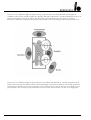
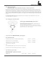
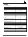
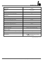
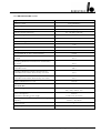
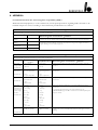
CHROMOPHARE®
D 660, D 540, D 510
Operating instructions
Single light and combination light
CONTENTS
PAGE
1. General
4-6
1.1
1.2
1.3
1.4
1.5
1.5.1
1.6
4-5
5
5
6
6
6
6
Introduction
Manufacturer’s notes
General information
Information about product liability
Incoming inspection
Permissible environment conditions
EC certification
2. Before Operating
2.1
2.2
2.3
2.4
2.5
2.6
7-9
Range of application (purpose)
Safety information
Installation instructions
Instructions for initial start-up
Visual and performance check
Cleaning, sterilization, disinfection
3. Components
3.1
3.2
3.3
3.4
10 - 11
CHROMOPHARE® D 660 / 660, / D 540 or / D 510 (flat cardanic)
CHROMOPHARE® D 660 / 660, / D 540 or / D 510 (classic cardanic)
CHROMOPHARE® D 540 and D 510 (flat cardanic)
CHROMOPHARE® D 540 and D 510 (classic cardanic)
4. Operation
4.1
4.2
4.3
4.4
4.4.1
4.4.2
4.5
4.5.1
4.5.2
4.6
2
7
7
8
8
8
9
10
10
11
11
12 - 18
Control panel and symbols CHROMOPHARE® D 660
Control panel and symbols CHROMOPHARE® D 540 and D 510
Control panel and symbols CHROMOPHARE® D 510
(without option “light intensity control”)
Notes on operation and positioning the lights
Adjusting the field size
Changing the sterilizable handle
Accessoires for CHROMOPHARE® operating lights
Sterilizable handle
Illuminants
System variants
CHROMOPHARE® D 660, D 540, D 510 Operating instructions (E)
12 - 13
13 - 14
14
15 - 17
17
17
17
17
17
18
CONTENTS
PAGE
5. Options
5.1
5.2
5.2.1
5.3
5.4
5.5
5.6
18 - 20
Options for CHROMOPHARE® D generation
Light Pilot System LFN (only for CHROMOPHARE® D 660)
Adjusting the field size for LFN model CHROMOPHARE® D 660
Changing the sterilizable handles - LFN model
Accessoires for CHROMOPHARE® D 660 LFN model - Light Pilot
EndoLite®
Camera system
6. Maintenance
6.1
6.2
6.3
20 - 22
Identification of the serial number and symbols used on the type plate
Notes on changing fuse
Instructions for changing lamps
7. Technical data
7.1
7.2
7.3
20
20
21 - 22
23 - 28
CHROMOPHARE® D 660
CHROMOPHARE® D 540
CHROMOPHARE® D 510
8. Appendix A
8.1
18
19
19
19
19
19
20
23 - 24
25 - 26
27 - 28
29
Information about the electromagnetic compatibility (EMC)
CHROMOPHARE® D 660, D 540, D 510 Operating instructions (E)
29
3
1. GENERAL
1.1 Introduction
The CHROMOPHARE® D 660, D 540 and D 510 consists of a swivel arm support, a lamp housing and a flange
tube .The lamp housing is fixed to a cardanic-type support (vertical gimbal joint, horizontal gimbal joint) and can
be rotated, swiveled and tilted in any direction. The height is adjusted via the 360° rotating vertical spring arm.
The spatial position of the lamp is adjusted by means of the 360° rotating horizontal swivel arm.
The special features of the CHROMOPHARE® D generation are:
• Dents and paint scratches or chips on the light hood are eliminated. An impact-absorbent light hood made of
polymer material prevents deformations and paint defects.
• Cool light in the surgical area and in the beam path of the operating lights, which is achieved by filtering out the
infrared proportion by means of the proven ThermoSorb® double filter system.
• The newly designed suspension and the hand grip with a particularly wide protective collar and an integrated
release mechanism, ensure a high degree of hygiene.
• Excellent depth of illumination and low shadow levels, which are achieved by modifying the light beam using
reflector elements.
• In the case of failure of the main lamp, 100 percent identical light ratios are guaranteed by the lamp-swivel
mechanism, which swings the reserve lamp into the position of the main lamp (D 510 optional).
Additional special features of the CHROMOPHARE® D 660:
• High illuminance of 160,000 lx for illuminating a deep surgical area, which is achieved with the assistance of the
newly developed energy reflection technology.
Additional special features of the CHROMOPHARE® D 540:
• High illuminance of 145,000 lx for illuminating a deep surgical area, which is achieved with the assistance of the
newly developed energy reflection technology.
Additional special features of the CHROMOPHARE® D 510:
• Illuminance of 130,000 lux for illuminating a deep surgical area, which is achieved with the assistance of the
newly developed energy reflection technology.
4
CHROMOPHARE® D 660, D 540, D 510 Operating instructions (E)
Additional optional characteristics of the CHROMOPHARE® D 510:
• Electronic light intensity control (65,000 Lux – 130,000 Lux)
• Light field size adjustment (170 mm - 280 mm)
• Reserve bulb with automatic switch over to reserve bulb operation and LED display
• Reserve lamp that swings into the optical centre for 100 % intensity in reserve operation
• Circumferential rail for simplifield handling
• Central integrated camera (optionally with fixed or adjustable zoom)
• Wall control
• EndoLite® for the illumination of the surroundings during endoscopic procedures
1.2 Manufacturer´s notes
The manufacturer of the products specified in these operating instructions is:
BERCHTOLD GmbH & Co. KG
Ludwigstaler Straße 25
Postfach 4052
78505 Tuttlingen / Germany
Internet: www.BERCHTOLD.de
e-mail: [email protected]
Tel. +49 (0) 74 61 / 181 - 0
Fax +49 (0) 74 61 / 181 - 200
1.3 General information
• This user’s manual is considered part of the equipment. It must be kept in the vicinity of the equipment at all
times. Precise observance of the user’s manual is a prerequisite for the proper use and correct operation of the
equipment, which is essential for the safety of patients and operators alike.
• Only accessories which are specified in this user’s manual, and which have been tested together with the
equipment, may be used. If accessories are used which are not specified in the user’s manual, their ability to be
used in accordance with safety regulations must be proved.
• All literature relates to the equipment model and the prevailing basic safety regulations when printed. All rights
are reserved for equipment, switches, procedures, software programs and names.
CHROMOPHARE® D 660, D 540, D 510 Operating instructions (E)
5
1.4 Information about product liability
BERCHTOLD considers itself responsible for the consequences of safety, reliability and performance of the
equipment only if:
a) installation, modifications or repairs have been performed only by BERCHTOLD, or by an agent expressly
authorized by BERCHTOLD to do so,
b) the electrical installation of the room complies with regulations IEC 60364-7-10, or the national electrical code,
NFPA 70x (NEC)
c) the equipment is used in accordance with the user’s manual.
1.5 Incoming inspection
Please inspect the equipment and accessories immediately after receipt for any transportation damage and defects.
Claims for damage will only be valid if the vendor (BERCHTOLD) or the carrier are informed
at once. A damage report must then be prepared immediately. The damage record must be submitted to the
nearest BERCHTOLD representative or to BERCHTOLD directly.
When an appliance or parts of an appliance are returned to BERCHTOLD or to a BERCHTOLD service agent,
the original packaging should be used where possible. The following accompanying documentation must be
attached: owner’s name and address, equipment number (see type plate), description of the defect.
1.5.1 Permissible environment conditions
For transport and storage (in original packing; for maximum 15 weeks)
Ambient temperature - between -10°C and +60°C, 14 ° F and 140 ° F
Relative air moisture - between 10 % and 85 %, no condensation
Air pressure
- between 500 hPa and 1060 hPa, 14.8 in Hg and 31.1 in Hg
For operation
Ambient temperature - between +10°C and +40°C, 50 ° F and 104 ° F
Relative air moisture - between 30 % and 75 %
Air pressure
- between 700 hPa and 1060 hPa, 20.7 in Hg and 31.3 in Hg
1.6 EC certification
The equipment complies with the requirements of the EC guideline regarding medical products, 93/42/EEC as
well as the UL guidlines. The certification with the EC marking is located on the type plate.
6
CHROMOPHARE® D 660, D 540, D 510 Operating instructions (E)
2. BEFORE OPERATING
2.1 Range of application (purpose)
The CHROMOPHARE® light is a medical light for use in hospital treatment rooms. It is used for the local
illumination of the patient’s body. It may only be used in rooms which have been correctly designed out in
accordance with IEC 60364-7-10, or NEC.
The CHROMOPHARE® light as a single light provides a very high degree of failure protection, as it is (optionally)
equipped with automatic switch-over to a reserve lamp, electronic monitoring with a “bypass switch” and an
automatic APU switch-over. However, not all components are duplicated, so that in some circumstances a failure
is still possible. As a matter of principle, single lights should not be used for operations where a light failure could
represent a great danger to the patient.
Light combinations with two or even three light heads provide more security against light failure and a better
brightness of the operating field. They provide light from different angles and maximum protection against light
failure due to the fact that components are redundant. This applies particularly when they are connected to an
emergency power supply (APU) in addition to the mains supply. These combination lights may be used in all
medical disciplines for the illumination of surgical areas.
2.2 Safety information
• Incorrect operation and non-observance of safety measures can cause serious consequences. Therefore make
sure that you have read and understood the information in your CHROMOPHARE® user’s manual.
• The light is not intended for operation in areas where there is danger of explosion.
• Do not look into the illuminated light and do not put any reflective objects into the path of the beam. Because of
the high illumination strength there is a danger of glare.
• The distance between the light emission surface area of the operating light and the patient surface should not be
less than 60 cm in order to ensure proper illumination.
• The light must not be operated if the cover glass or the filter system is damaged or destroyed. Thermal radiation
can reach the surgical area, heating up and drying out the tissue of the operation wound. If the effect is
prolonged, there is even the danger of tissue necrosis.
• Do not place any objects on the lamp housing or hang objects on arms or lamp housings, as this may
compromise the stability of the support and there is the danger that these objects may fall into the surgical area.
Attaching or hanging heavy objects can destroy the mechanism.
• The lamp housing must not be covered while in operation, as this prevents heat exchange with the environment
and could cause the surgical light to overheat.
• Collision of the supporting arms and lamp housings should to be avoided. A severe collision could result in lights
being damaged or parts falling into the surgical area.
• The overlay of the light fields can cause an increase in heat generation.
CHROMOPHARE® D 660, D 540, D 510 Operating instructions (E)
7
2.3 Installation instructions
Due to their high rotational moments and self-weights, the installation and mounting of all CHROMOPHARE®
lights on the ceiling of the operating room must be performed by BERCHTOLD personnel or by a contractor
authorized by BERCHTOLD, in accordance to BERCHTOLD “Mounting instructions for ceiling lights”.
The electrical installation must comply with the customer’s code requirements.
Incorrect assembly of the lights can result in damage to the mounting system and potential risk to the patient and
staff. The on-site electric installation must be performed in accordance with IEC 60364-7-10 or NEC and include
a fuse protection as well as a mains switch for a simultaneous, dual pole separation of the light. For further
information, please note the mounting instructions.
2.4 Instructions for initial start-up
The operator may begin to use the light, after the manufacturer or supplier
a) has carried out a performance check at the place of operation,
b) has introduced those responsible for the operation of the light to its correct handling by means of the user’s
manual.
2.5 Visual and performance check
Before initial start-up the manufacturer or supplier should check that the CHROMOPHARE® light has been
properly installed and is in a safe and operational condition.
A visual inspection of the following points must take place:
• After switching-on the unit, light must be emitted from the main lamp, and in the case of combination lights,
also from the additional lamp.
• Inspection of the light emission lens of the lamp housing
If the light emission lens is damaged or broken, glass splinters can fall out. The light must be switched off
immediately and must not be used until the defect has been rectified.
• Inspection of the reserve lamp warning indicator
In the case of failure of the main lamp, the reserve lamp is automatically switched on and swung into the
position of the main lamp (D 510 optional). The yellow warning indicator on the lamp housing illuminates to
indicate this error. The defective main lamp must be replaced immediately.
• Checking the operational state of the control unit (D 510 only with option “light intensity control”)
The individual functions must be checked by activating the appropriate keys. Faults in the main circuit of the
control electronics are indicated by the red fault indicator on the control unit. In this case the light operates at its
maximum luminous intensity and can no longer be controlled via the keys.
• Checking the mechanical movement mechanism of the system
The mechanical operation of the light system is checked by swiveling and rotating the movement mechanism.
8
CHROMOPHARE® D 660, D 540, D 510 Operating instructions (E)
2.6 Cleaning, sterilization, disinfection
• All parts of the CHROMOPHARE® light can be cleaned with standard commercial cleaners on all exterior
surfaces including the control unit, and disinfected with the disinfectants normally used in surgical areas.
• Only disinfectants may be used, that are certified from the manufacturer for the following materials:
Polycarbonate (PC), Polyamid (PA), Polyvinylclorid (PVC), Acrylnitril-Butadiene-Styrol-Copolymer (ABS),
Polyetherimide (PEI) and Silicones.
• Cleaning, disinfectant and sterilization of the sterilizable handles
The sterilizable handles are made of heat-resistant, impact-resistant plastic (PEI). They
can be cleaned with mild alkaline cleaners without active chlorine. The cleaners must be thoroughly rinsed off
with water. Alternatively, the hand-grip holders can be cleaned mechanically with heat-disinfection up to a
maximum temperature of 93°C/10 min.
For disinfecting the handle sleeves we recommend products with an alcohol or aldehyde base. The sleeves must
be rinsed before sterilization.
The handles can be sterilized in steam. The recommended parameters are:
1. Steam sterilization at 121° C; 1.3 bar (18.9 PSI); 25 to 30 minutes
2. Steam sterilization at 134° C; 2.3 bar; (33.3 PSI); 4 minutes
When filling the autoclave ensure that the open side of the handles are face down. The sleeves must lie free and
must not come into contact with any other items being sterilized.
Hot-air sterilization is not recommended by BERCHTOLD. However, if it is necessary, the handles should be
sterilized at 134° C; 3 minutes.
Note:
Sterilizable handles are subject to natural wear.
As a rule, a life of approx. 100 cleaning cycles is normal.
Damaged grip sleeves must not continue to be used.
The operator should refer to recongnized standards for hygiene and disinfection
CHROMOPHARE® D 660, D 540, D 510 Operating instructions (E)
9
3. COMPONENTS
3.1 CHROMOPHARE® D 660 / D 660, / D 540 or / D 510 (flat cardanic)
1
2
3
4
5
6
Ceiling cover
Flange tube Æ 125 mm
Horizontal swivel arm
Vertical spring arm
Horizontal gimbal joint
Lamp housing hood
7
8
9
10
11
Lamp frame
Light emission lens
Sterilizable handle
Rail (encircling hand grip)
Control panel
3.2 CHROMOPHARE® D 660 / D 660, / D 540 or / D 510 (classic cardanic)
1
2
3
4
5
6
10
Ceiling cover
Flange tube Æ 125 mm
Horizontal swivel arm
Vertical spring arm
Vertical gimbal joint
Horizontal gimbal joint
7
8
9
10
11
12
Lamp housing hood
Lamp frame
Light emission lens
Sterilizable handle
Rail (encircling hand grip)
Control panel
CHROMOPHARE® D 660, D 540, D 510 Operating instructions (E)
3.3 CHROMOPHARE® D 540 and D 510 (flat cardanic)
1
2
3
4
5
6
7
8
9
10
11
Ceiling cover
Flange tube Æ 65 mm
Horizontal swivel arm
Vertical spring arm
Horizontal gimbal joint
Lamp housing hood
Lamp frame
Light emission lens
Sterilizable handle
Rail (encircling hand grip)
Control panel
3.4 CHROMOPHARE® D 540 and D 510 (classic cardanic)
1
2
3
4
5
6
7
8
9
10
11
12
Ceiling cover
Flange tube Æ 65 mm
Horizontal swivel arm
Vertical spring arm
Vertical gimbal joint
Horizontal gimbal joint
Lamp housing hood
Lamp frame
Light emission lens
Sterilizable handle
Rail (encircling hand grip)
Control panel
CHROMOPHARE® D 660, D 540, D 510 Operating instructions (E)
11
4. OPERATION
4.1 Control panel and symbols CHROMOPHARE® D 660
The following functions can be controlled by the control panel:
1 ON
2 OFF
3 Bright
4 Dark
5 Fault
Switch on the light
Switch off the light
Increase intensity (the reach of the maximum intensity will be displayed by a
light emitting diode)
Decrease intensity (the reach of the minimum will be displayed by a light
emitting diode)
LED indicates that the control unit has a fault
Options:
6
7
8
9
EndoLite®
OR light
Field size large
Field size smal
Switch from surgical area light to surround light (only with option EndoLite®)
Switch from surround light to surgical area light (only with option EndoLite®)
Enlarge field size (only with option LFN)
Reduce field size (only with option LFN)
ON
The OR light is switched on by pressing key 1.
OFF
The OR light is switched off by pressing key 2.
Bright
By pressing and holding down key 3 the illuminance is continuously increased up to the maximum
value. Repeated short presses increase the illuminance in steps.
Dark
By pressing and holding down key 4 the illuminance is continuously reduced down to the minimum
value. Repeated short presses decrease the illuminance in steps.
Fault
If the indicator light shows red, there is a fault in the control unit electronics.
EndoLite® Only with the EndoLite® option. By pressing key 6 EndoLite® the surgical area illumination is
switched off and the surround lighting is switched on.
12
CHROMOPHARE® D 660, D 540, D 510 Operating instructions (E)
OR light
Only with the EndoLite® option. By pressing key 7 the EndoLite® surround lighting is
switched off and the surgical area lighting is switched on again.
Field size large
Only with the LFN model. By pressing and holding down key 8 the light field is continuously
enlarged up to the maximum value. Repeated short presses enlarge the light field in steps.
Field size small
Only with the LFN model. By pressing and holding down key 9 the light field is continuously
reduced down to the minimum value. Repeated short presses reduce the light field in steps.
4.2 Control panel and symbols CHROMOPHARE® D 540 and D 510 with “light intensity control” and
EndoLite® (only in conjunction with option “light intensity control”)
The following functions can be controlled by the control panel:
1 ON
2 OFF
3 Bright
4 Dark
5 Fault
Switch on the light
Switch off the light
Increase intensity (the reach of the maximum intensity will be displayed by a
light emitting diode)
Decrease intensity (the reach of the minimum intensity will be displayed by a
light emitting diode)
LED indicates that the control unit has a fault
Options:
6 EndoLite®
7 OR light
Switch from surgical area light to surround light (only with option EndoLite®)
Switch from surround light to surgical area light (only with option EndoLite®)
ON
The OR light is switched on by pressing key 1.
OFF
The OR light is switched off by pressing key 2.
Bright
By pressing and holding down key 3 the illumination is continuously increased up to the maximum
value. Repeated short presses increase the illumination in steps.
CHROMOPHARE® D 660, D 540, D 510 Operating instructions (E)
13
Dark
By pressing and holding down key 4 the illumination is continuously reduced down to the minimum
value. Repeated short presses decrease the illumination in steps.
Fault
If the indicator light shows red, there is a fault in the control unit electronics.
Option:
EndoLite® Only with the EndoLite® option. By pressing key 6 the surgical area illumination is switched off and
the surround lighting is switched on.
OR light
Only with the EndoLite® option. By pressing key 7 the EndoLite® surround lighting is switched off
and the surgical area lighting is switched on again.
4.3 Control panel and symbols CHROMOPHARE® D 510 (without option “light intensity control”)
The following functions can be controlled by the control panel:
1 ON
2 OFF
14
Switch on the light
Switch off the light
ON
The OR light is switched on by pressing key 1.
OFF
The OR light is switched off by pressing key 2.
CHROMOPHARE® D 660, D 540, D 510 Operating instructions (E)
4.4 Notes on operation and positioning the lights
Before an operation the lamp housing should be placed in an initial position, so that it can later be easily adjusted
both horizontally and vertically. In the case of a single light, it is positioned over the center of the surgical area
(see illustration 1). The distance from the lower edge of the light to the operating table is approx. 1.15 m (45″).
Initial positioning is accomplished by using the rail on the lamp housing (D 510 optional). The surgeon has the
option of adjusting the light using the center hand grip, which is provided with a replaceable sterilized sleeve. In
the case of combination lights the main light is positioned over the center of the surgical area and the additional
light over the foot area.
The light should be set in the basic position so that the position of the lamp housing may be changed easily
without using force and the control unit can be reached easily by “non-sterile” personnel to adjust the brightness.
CHROMOPHARE® D 660, D 540, D 510 Operating instructions (E)
15
In the case of a combination light the lamp housings are positioned so that the light fields of both lights are
coincident. The operator should consider the following: The light’s adjustment to maximum illumination causes an
increased desiccation of the tissue. Swivel and spring arms are positioned in the basic setting as shown in
illustration 2. With this arrangement the position of the lamps can be easily changed without using undue force.
In the case of a combination light the basic setting is in accordance with illustration 2. In this arrangement both
lamps can be easily moved, and the control units of both lamps can be easily reached by “non-sterile” personnel.
In operations in which it is necessary to intervene at two separate points as may be the case, for example, in a bypass procedure, the two lamps are positioned above the two points of intervention as if they were single lights.
16
CHROMOPHARE® D 660, D 540, D 510 Operating instructions (E)
4.4.1 Adjusting the field size
CHROMOPHARE® D 660, D 540, D 510 (with option “ field size adjustment”)
By turning the sterilizable center hand grip the size of the light field is changed. By turning the hand grip in the
clockwise direction the light field is enlarged, by turning counter-clockwise the light field is reduced. The surgeon
must perform the optimum field setting himself in accordance with the size of the operation opening. There is an
optimum contrast when the field size is set approx. 1 cm larger than the operation opening, so that the edge of the
sterile covering is also illuminated. The adaptation of the surgeon’s eyes is, therefore, improved in the whole field
of vision.
On CHROMOPHARE® D 660 with the Light pilot option, the adaption of the field diameter is done at the
control panel (please see chapter 4.1).
4.4.2 Changing the sterilizable handles
Operating lights CHROMOPHARE® D-Generation
By pressing the release button the handle is released and can be
removed from the sleeve mounting.
The new, sterilized replacement sleeve is pushed onto the sleeve
mounting until it touches the stop and is then turned in a clockwise
direction until the sleeve locks into place.
4.5 Accessories for CHROMOPHARE® operating lights
4.5.1 Sterilizable handles
• Standard replacement sleeve (D 660, D 540 and D 510)
Order no.
CZ 499-06
• Replacement sleeve for LFN (D 660)
Order no.
CZ 498-04
• Replacement sleeve for light system with
ChromoVision® AFII & FZ
Order no.
CZ 498-08
Order no.
CZ 909-22
Note!
Each CHROMOPHARE® light is delivered with two sterilizable handles.
For directions about cleaning, disinfection and sterilization, see chapter 2.6.
4.5.2 Illuminants (reserve bulb)
CHROMOPHARE® D 660, D 540 and D 510
• BRITe-bulb
22.8 V/ 150 W
CHROMOPHARE® D 660, D 540, D 510 Operating instructions (E)
17
4.6 System variants
The CHROMOPHARE® D generation is available in the following system variants:
1. CHROMOPHARE® D 660 as a combination light with D 540 or D 510
2. CHROMOPHARE® D 540 as a combination light with D 660 or D 510
3. CHROMOPHARE® D 540 as a mobile light (with transformer or battery)
4. CHROMOPHARE® D 540 as a wall light
5. CHROMOPHARE® D 510 as a single, double and triple light
6. CHROMOPHARE® D 510 as a mobile light (with transformer)
5. OPTIONS
5.1 Options for CHROMOPHARE® D generation
The CHROMOPHARE® D generation can be supplemented or upgraded with the following options:
• Light carrier arm for up to 11 kg load with AC and grounding connections for an auxiliary device (only possible
if the light has been prepared for an aditional arm in advance).
• Monitor support arm for up to 10 kg load with AC and Video connections for LCD-Monitor.
• Double monitor support arm for up to 27 kg load with AC and Video connections for two LCD monitors.
• Wall control unit for installation into a wall indicator panel. Functions such as switching on / off and brightness
of the OR light can then be controlled from the wall (not upgradeable).
• External camera support arm for up to 5.1 kg load for mounting an external camera.
5.2 Light Pilot System LFN (only for CHROMOPHARE® D 660)
The CHROMOPHARE® D 660 can be ordered with an LFN System as an option. The LFN System is an
electronic control system, which moves the lamps by electric motor. An infrared beam which is reflected by a
reflector disk controls the LFN System.
The operator can direct the light field to the position which guarantees
optimum illumination of the surgical area, by means of a reflector disk, the
so-called “Light Pilot”.
The “Light Pilot” should be held in the center of the light field as far as
possible and then slowly moved to the desired position. If movement is
too quick, the light field will not be able to follow the “Light Pilot”.
This rule is: Wherever the light field is , the “Light Pilot” will be hit by the
infrared beam and can reflect the beam back.
18
CHROMOPHARE® D 660, D 540, D 510 Operating instructions (E)
5.2.1 Adjusting the field size for LFN model CHROMOPHARE® D 660
The CHROMOPHARE® D 660 with LFN allows the field size to be adjusted by an electric motor. By pressing
and holding down key 8 the light field is continuously enlarged up to the maximum value. By repeated short
presses the light field is enlarged in steps. By pressing and holding down key 9 the light field is continuously
reduced down to the minimum value. By repeated short presses the light field is reduced in steps.
5.3 Changing the sterilizable handles - LFN model
The sterilizable hand grip sleeve is released by pressure on the bolt on the
upper collar of the sleeve. It can then be removed from the sleeve
mounting. The new sterilized replacement sleeve is pushed onto the sleeve
mounting until it touches the stop and is then turned in a clockwise
direction until the sleeve is heard locking into place.
5.4 Accessoires for CHROMOPHARE® D 660 LFN model - Light Pilot
• Light Pilot for single LFN (resp. 10 pieces)
Order no. CZ 498-10
• Light Pilot for multiple LFN (resp. 10 pieces)
Order no. CZ 498-20
Note!
The “Light Pilot” can be cleaned and disinfected with normal detergents and disinfectants or gas-sterilized to a maximum temperature
of 70°. “The Light Pilot” must not be sterilized with steam or hot air. This device is designed for approximately 10 sterilization-cycles
and is supplied non-sterilized.
5.5 EndoLite®
The CHROMOPHARE® D 660, D 540 and D 510 (only in conjunction with option “light intensity control”)
model can be ordered with an optional environment illumination function (EndoLite®) for endoscopic operations.
Room illumination with greatly reduced intensity is often installed for endoscopic operations so as not cause a
disturbance to surgeons or operators and to facilitate observation of the monitors.
It is also possible to install the EndoLite® option at a later date in the CHROMOPHARE® D 660, D 540 and D 510
lamp. Operating room illumination is obtained by means of a 20 W halogen lamp incorporated in the lamp body
housing, and directing light upwards.
By pressing key 6 “EndoLite®” the surgical area illumination is
switched off and the surround lighting is switched on.
By pressing key 7 “OR-light” again, the EndoLite® surround
lighting is switched off and the surgical lighting is switched on
again.
Reserve bulb 12 V/20 W
Order no. CZ 960-12
CHROMOPHARE® D 660, D 540, D 510 Operating instructions (E)
19
5.6 Camera system
(D 510 ChromoVision® AFII or HR24 only in conjunction with option “light field size adjustment”)
You can order our CHROMOPHARE D 660, D 540 and D 510 either with a BERCHTOLD camera system
ChromoVision® AF II (HR24) or ChromoVision® FZ (Pal or NTSC). Note that the camera system can be
installed in a standard model at a later date provided that the lamp already being used is designed for installation of
the camera system. If you use the camera system please note that you cannot use the option LFN.
The BERCHTOLD ChromoVision® camera system allows the user to record the various phases of an
operation for didactic and documentary purposes. In the BERCHTOLD ChromoVision® system a camera is fitted
in the central hand grip of the lamp, which can be worked by means of an external control.
It is possible to obtain live viewing of an operation with a monitor or record an operation with video-recording
equipment.
The use and characteristics of the lamp are, generally speaking, unvaried whenever a camera is used. The light field
width cannot be adjusted however when the television function is used. Use and installation of the camera system
are illustrated separately in the “Operating Instructions” of the ChromoVision® model.
6. MAINTENANCE
6.1 Identification of the serial number and symbols used on the type plate
The type plate for the surgical light is located on the light head directly beside the control panel.
Type plate
1 Version number
2 Variation
3 Manufacturing year
4 Serial number
5 EC certification
6 Symbol for camera preparation
7 Health Industry Bar Code
The CHROMOPHARE® lights should be serviced once a year (maintenance contract).
Maintenance should only be performed by BERCHTOLD or by a company authorized by BERCHTOLD (see
notes on product liability). Before performing any ordinary maintenance, power to the light heads should be
disconnected.
6.2 Notes on changing fuse
In this lamp, the mains fuses and the fuses for the emergency power supply are not located in the flange under the
cover but are located externally, in the switchboard and electric control panel respectively, so as to allow for easy
replacement in the case of an illumination failure.
The value of fuse are withdraw from the CHROMOPHARE® mounting instruction for ceiling lights.
20
CHROMOPHARE® D 660, D 540, D 510 Operating instructions (E)
6.3 Instructions for changing bulbs
The BRITe-bulb has an average life of 1000 hours. In the event
of failure of the main lamp, switch over to a reserve lamp occurs
automatically and the reserve lamp swivels automatically into the
former position of the main lamp (D 510 optional).
A yellow indicator light up on the lamp housing when the lamp
safety system has switched over to the reserve lamp. The
defective main lamp should then be exchanged as quickly as
possible.
The bulbs must be replaced in the following manner:
Attention!
If changing the bulb, please wear glasses!
The symbol “Danger - Risk of Burning” is placed on the lamp support.
Do not touch the quartz cone of the illuminant with your bare fingers, use a
cloth or soft paper.
Switch off the lighting system and let it cool down (risk of
burning).
Release and remove sterilizable hand grip before.
Unscrew the knurled screw (M1 – M3) on the underside of the
light by turning counter-clockwise.
CHROMOPHARE® D 660, D 540, D 510 Operating instructions (E)
21
Pull out the whole light system at the hand grip.
Remove the faulty bulb. We advise users to insert the reserve bulb
(optional) into the main light bulb holder , marked with <R>, and
to insert the new bulb in the reserve bulb holder so that the
reserve bulb maintains adequate life.
Fit a new BRITe-bulb into the bulb holder, - for the booking
reference number see chapter 4.5.2 Illuminants - ( do not touch
the quartz cone of the BRITe-bulb with your bare fingers, use a
cloth or soft paper). During a lamp change check the bulb holder
for scorch marks. If scorch marks are present, inform
BERCHTOLD service department.
Fit the light system back into the holder and screw the knurled
screws in a clockwise direction.
Switch the lighting system on and check that the lamp is on and
the red indicator light is off (D 510 optional).
Note!
Only use original BERCHTOLD BRITe-bulbs. If other bulbs are used, all guarantees regarding
performance and operation will be void.
22
CHROMOPHARE® D 660, D 540, D 510 Operating instructions (E)
7. TECHNICAL DATA
7.1 CHROMOPHARE® D 660
Light technical data
Reflector system
D 660
Polygonreflector
Colour temperature
4300 K
Intensity Ec at 1 m
160 [klx]
Intensity control
80 - 160 [klx]
Total radiant power at max intensity
Total radiant power/intensity Ec
Colour rendering index Ra
acv
560 W/m2
3.5 [mW/m2lx]
93
0.58
Light field diameter
17 - 30 cm
d10 Light field dia. at 10 % of max intensity
17 cm
d50 Light field dia. at 50 % of max intensity
8.5 cm
Remaining illuminance when beam is obstructed by
one mask
47 %
Remaining illuminance when beam is obstructed by
two masks
45 %
Remaining illuminance inside at the bottom of a
standardized tube
100 %
Remaining illuminance inside at the bottom of a
standardized tube. Beam obstructed by one mask
47 %
Remaining illuminance inside at the bottom of a
standardized tube. Beam obstructed by two masks
45 %
Depth of illumination L1 + L2
120 cm
Electrical data
Primary voltage of transformer
100 / 120 / 127 V A.C.
220 / 230 / 240 V A.C.
Power consumption
transformer/switching power supply
240 VA
or 170 AV at 24 V D.C.
Rated capacity of transformer/switching power supply,
frequency
Safety Category
240 VA / 50/60 Hz
1
Protection provided by enclosure
IP 53
CHROMOPHARE® D 660, D 540, D 510 Operating instructions (E)
23
General data
D 660
BRITe-bulb
Order no.
22.8 V / 150 W
CZ 909-22
Life time of BRITe-bulb
Automatic switch over to reserve bulb
1000 h
yes
Dimensions
Diameter of light body
65 cm
Diameter of polygonreflector
58.5 cm
Light emission surface (glass surface)
2370 cm2
Max. swivel radius
237 cm
Lowest position of light body (N.C.)
128 cm
Highest position of light body (N.C.)
254 cm
Lowest position of light body (A.C.)
102 cm
Highest position of light body (A.C.)
225 cm
Clearance (single light)
200 cm at 265 cm finished ceiling
Weight / Torque
Weight with transformer/switching power supply
Max. torque
Certifications
50 kg
342 Nm
Conformity with 93/42 EEC
UL classified
Light technical data ± 10 %
24
CHROMOPHARE® D 660, D 540, D 510 Operating instructions (E)
7.2 CHROMOPHARE® D 540
Light technical data
Reflector system
D 540
Polygonreflector
Colour temperature
4300 K
Intensity Ec at 1 m
145 [klx]
Intensity control
72.5 - 145 [klx]
Total radiant power at max intensity
Total radiant power/intensity Ec
Colour rendering index Ra
acv
507 W/m2
3.5 [mW/m2lx]
93
0.58
Light field diameter
17 - 28 cm
d10 Light field dia. at 10 % of max intensity
17 cm
d50 Light field dia. at 50 % of max intensity
8.5 cm
Remaining illuminance when beam is obstructed by
one mask
22 %
Remaining illuminance when beam is obstructed by
two masks
45 %
Remaining illuminance inside at the bottom of a
standardized tube
100 %
Remaining illuminance inside at the bottom of a
standardized tube. Beam obstructed by one mask
22 %
Remaining illuminance inside at the bottom of a
standardized tube. Beam obstructed by two masks
45 %
Depth of illumination L1 + L2
125 cm
Electrical data
Primary voltage of transformer
100 / 120 / 127 V A.C.
220 / 230 / 240 V A.C.
Power consumption
transformer/switching power supply
240 VA
or 170 VA at 24 V D.C.
Rated capacity of transformer/switching power supply,
frequency
Safety Category
240 VA 50/60 Hz
1
Protection provided by enclosure
IP 53
CHROMOPHARE® D 660, D 540, D 510 Operating instructions (E)
25
General data
D 540
BRITe-bulb
Order no.
22.8 V / 150 W
CZ 909-22
Life time of BRITe-bulb
Automatic switch over to reserve bulb
1000 h
yes
Dimensions
Diameter of light body
52 cm
Diameter of polygonreflector
45.5 cm
Light emission surface (glass surface)
1374 cm2
Max. swivel radius
231 cm
Lowest position of light body (N.C.)
130 cm
Highest position of light body (N.C.)
219 cm
Lowest position of light body (A.C.)
112 cm
Highest position of light body (A.C.)
213 cm
Clearance (single light)
200 cm at 245 cm finished ceiling
Weight / Torque
Weight with. transformer/switching power supply
Max. torque
Certifications
35 kg
269 Nm
Conformity with 93/42 EEC
UL classified
Light technical data ± 10%
26
CHROMOPHARE® D 660, D 540, D 510 Operating instructions (E)
7.3 CHROMOPHARE® D 510
Light technical data
Reflector system
D 510
Polygonreflector
Colour temperature
4300 K
Intensity Ec at 1 m
130 [klx]
Intensity control (electronic)
Total radiant power at max intensity
Total radiant power / intensity Ec
Colour rendering index Ra
acv
65 - 130 [klx] (optional)
455 W / m2
3.5 [mW / m2lx]
93
0.58
Light field adjustment
17 - 28 (optional)
d10 Light field dia. at 10 % of max intensity
17 cm
d50 Light field dia. at 50 % of max intensity
8.5 cm
Remaining illuminance when beam is obstructed by
one mask
22 %
Remaining illuminance when beam is obstructed by
two masks
45 %
Remaining illuminance inside at the bottom of a
standardized tube
100 %
Remaining illuminance inside at the bottom of a
standardized tube. Beam obstructed by one mask
22 %
Remaining illuminance inside at the bottom of a
standardized tube. Beam obstructed by two masks
45 %
Depth of illumination L1 + L2
125 cm
Electrical data
Primary voltage of transformer
100 / 120 / 127 V A.C.
220 / 230 / 240 V A.C.
Power consumption
transformer/switching power supply
240 VA
or 170 VA at 24 V D.C.
Rated capacity of transformer/power switching supply,
frequency
Safety Category
240 VA / 50/60 Hz
1
Protection provided by enclosure
IP 53
CHROMOPHARE® D 660, D 540, D 510 Operating instructions (E)
27
General data
D 510
BRITe-bulb
Order no.
22.8 V / 150 W
CZ 909-22
Life time of BRITe-bulb
Automatic switch over to reserve bulb
1000 h
yes (optional)
Dimensions
Diameter of light body
52 cm
Diameter of polygonreflector
45.5 cm
Light emission surface (glass surface)
1374 cm2
Max. swivel radius
231 cm
Lowest position of light body (N.C.)
130 cm
Highest position of light body (N.C.)
219 cm
Lowest position of light body (A.C.)
112 cm
Highest position of light body (A.C.)
213 cm
Clearance (single light)
200 cm at 245 cm ceiling high
Weight / Torque
Weight with. transformer/switching power supply
Max. torque
Certifications
35 kg
269 Nm
Conformity with 93/42/EEC
UL classified
Light technical data ± 10 %
28
CHROMOPHARE® D 660, D 540, D 510 Operating instructions (E)
8. APPENDIX A
8.1 Information about the electromagnetic compatibility (EMC)
Medical electrical Equipment, so as the attached one, needs special precautions regarding EMC and needs to be
installed and put into service according to the information provided in the user manual.
Guidance and manufacturer's declaration – electromagnetic emissions
The CHROMOPHARE lights are intended for use in the electromagnetic environment specified below. The customer or the user of the
CHROMOPHARE lights should assure that it is used in such an environment.
Emissions test
Compliance
Electromagnetic environment - guidance
RF emissions
CISPR11
Group 1
The CHROMOPHARE lights uses RF energy only for its internal function. Therefore, its RF
emissions are very low and are not likely to cause any interference in nearby electronic equipment.
RF emissions
CISPR11
Class B
Harmonic emissions
IEC 61000-3-2
Class A
The CHROMOPHARE lights are suitable for use in all establishments, including domestic
establishments and those directly connected to the public low-voltage power supply network that
supplies buildings used for domestic purposes.
Voltage fluctuations
Complies
Guidance and manufacturer's declaration – electromagnetic immunity
The CHROMOPHARE lights are intended for use in the electromagnetic environment specified below. The customer or the user of the
CHROMOPHARE lights should assure that it is used in such an environment.
Immunity test
Electrostatic
discharge (ESD)
IEC 60601test level
Compliance level Electromagnetic environment - guidance
± 6 kV contact
± 6 kV contact
± 8 kV air
± 8 kV air
Electrical fast
transient/burst
± 2 kV
for power supply lines
± 2 kV
for power supply lines
IEC 61000-4-4
± 1 kV
for input/output lines
± 1 kV
for input/output lines
Surge
± 1 kV
differential mode
± 1 kV
differential mode
± 2 kV
common mode
± 2 kV
common mode
< 5 % UT
for ½ cycle
(> 95 % dip)
< 5 % UT
for ½ cycle
(> 95 % dip)
40 % UT
40 % UT
for 5 cycles
(60 % dip)
for 5 cycles
(60 % dip)
70% UT
for 25 cycles
(30 % dip)
70% UT
for 25 cycles
(30 % dip)
< 5 % UT
for 5 s
(> 95 % dip)
< 5 % UT
for 5 s
(> 95 % dip)
3 V/m
80 MHz bis 2,5 GHz
3 V/m
80 MHz bis 2,5 GHz
Synthetic floors should be antistatic and the relative humidity should be at
least 30 %.
IEC 61000-4-2
IEC 61000-4-5
Voltage dips,
short
interruptions and
voltage variations
on power supply
input lines
IEC 61000-4-11
Radiated electric
field
Mains power quality should be that of a typical commercial or hospital
environment.
Mains power quality should be that of a typical commercial or hospital
environment.
Mains power quality should be that of a typical commercial or hospital
environment.
For continued operation during power mains interruptions, the
CHROMOPHARE lights should be connected to an uninterruptible power
supply or a battery.
If image distortion occurs by lights with camera system, it may be necessary
to position the sources of electric fields further from the lights or install
shielding.
IEC 61000-4-3
NOTE:
UT is the a.c. mains voltage prior to application of the test level.
CHROMOPHARE® D 660, D 540, D 510 Operating instructions (E)
29
57088/F-S/D/06.2006 © BERCHTOLD GmbH & Co. KG
Reproduction, including excerpts, prohibited.
Alterations in technology and design reserved.
30
BERCHTOLD GmbH & Co. KG
Ludwigstaler Straße 25
Postfach 4052
78505 Tuttlingen / Germany
Internet: www.BERCHTOLD.de
e-mail: [email protected]
Tel. +49 (0) 74 61 / 181 - 0
Fax +49 (0) 74 61 / 181 - 200
Technical service:
Tel. +49 (0) 74 61 / 181 - 217
Fax +49 (0) 74 61 / 181 - 311
CHROMOPHARE® D 660, D 540, D 510 Operating instructions (E)