1
OWS v1.3.2
1-Wire software package
User Manual
February 2014
OWS v1.3.2
Table of Contents
1
Distribution
5
2
Installation
Linux
Windows
5
5
5
3
Third-party Software Packages
5
4
1-Wire Support
1-Wire Controllers
1-Wire Adapters
1-Wire Sensor And Input Devices
1-Wire Control And Output Devices
6
6
6
6
6
1-Wire Bus Speeds
6
5
Concepts
6
Usage
Example Commands
Command Line Processing
Representation of Hardware
Selecting 1-Wire Adapters
LibUSB
I2C
TMEX
Serial
Selecting a Range of Channels
Maximal Number of Concurrent Tasks
Dumping Information
8
8
8
9
10
10
11
11
12
13
13
14
7
Program owsenum
Command Line
Hubs
Hobby Boards 4-Channel Hub
DS2409
Program Exit Status
Example Invocations of the Program
15
15
15
15
16
16
16
8
Program owsprobe
Command Line
Program Exit Status
Example Invocations of the Program
17
17
17
17
2
7
User Manual
OWS v1.3.2
9
Program owrgbctrl
Command Line
Program Exit Status
Example Invocations of the Program
18
18
18
19
10 Program owswitch
Command Line
Program Exit Status
Example Invocations of the Program
20
20
20
20
11 Program owhbh4
Command Line
Program Exit Status
Example Invocations of the Program
21
21
21
21
12 Program owsmlc
23
Command Line
Program Exit Status
Example Invocations of the Program
23
24
24
13 Program owspio
Command Line
1-Wire Devices
Program Exit Status
Example Invocations of the Program
25
25
26
26
26
14 Program owsrds
Command Line
Program Output
Temperature Sensors
Maxim DS2438
Maxim DS2406
Maxim DS2408
Maxim DS2413
Maxim DS2423
Maxim DS2760/DS2761/DS2762
Program Exit Status
Example Invocations of the Program
27
27
28
30
31
32
33
33
34
34
35
35
15 Topology Files
Overview
Text Encoding
Manual Editing
Usage
Contents
36
36
36
36
37
37
User Manual
3
OWS v1.3.2
16 Serial Paths
Linux
Windows
40
40
41
17 Troubleshooting
Error 4008 on BCM2835-based Computer
Program Fails Every Other Time
LibUSB and TMEX are Fighting
42
42
42
43
18 Software Design
Threading
Libraries
43
43
43
19 Software Revision History
44
20 Software License
45
21 Disclaimer
45
22 Contact Information
45
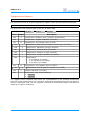
Revision History
Date
Authors
Description
2013-04-21 Peter S'heeren
Initial release.
2013-04-29 Peter S'heeren
Added section about serial-to-1-Wire adapters.
Added software revision history.
Added section about program owhbh4.
2013-05-23 Peter S'heeren
Added section about program owsrds.
Added section about topology files.
Updated numerous sections.
2013-06-08 Peter S'heeren
Added section about 1-Wire support.
Updated numerous sections.
2013-06-17 Peter S'heeren
Added section about hubs with program owsrds.
2013-06-27 Peter S'heeren
Added section about program owsmlc.
Added section about program owspio.
2013-09-11 Peter S'heeren
Updated various sections.
2014-02-01 Peter S'heeren
Updated various sections.
4
User Manual
OWS v1.3.2
1 Distribution
The software is available for various systems. Each software package is provided as a
compressed archive file.
2 Installation
Linux
Unpack the package in a local directory in your home directory. Be sure you pick the
distribution that corresponds with your operating system.
Run the install.sh script in the context of your user account to install the software.
Be sure to run the installation script from the command line rather than the file manager.
The script will sudo and as such the system may ask for the root password.
The installation script will install the programs in directory /opt/ows.
Windows
Unpack the package for Win32 in a local directory on your system.
Run the programs in the local directory from the command prompt (cmd.exe).
3 Third-party Software Packages
TMEX is provided by Maxim Integrated:
http://www.maximintegrated.com/products/ibutton/software/tmex/
The web page of the LibUSB project can be found here:
http://www.libusb.org/
Project libusbx is an alternative for the LibUSB project. It serves as a drop-in
replacement for the LibUSB library.
http://libusbx.org/
Project libwdi provides a driver installation tool for Windows XP and later called zadig.
It's advised to download and install this tool when you're planning to use USB-to-1-Wire
adapters on Windows. It'll help you to update your USB-to-1-Wire adapters to the drivers
that work best for your Windows system.
http://sourceforge.net/projects/libwdi/files/zadig/
User Manual
5
OWS v1.3.2
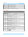
4 1-Wire Support
1-Wire Controllers
▪
Maxim DS2490 USB-to-1-Wire chip.
▪
Maxim DS2480/DS2480B serial-to-1-Wire chip.
▪
Maxim DS2482-100 I2C-to-1Wire chip.
▪
Maxim DS2482-800 I2C-to-1Wire chip.
1-Wire Adapters
▪
Axiris AbioWire.
▪
m.nu 1-Wire Adapter.
▪
Maxim DS9490R/DS9490B USB-to-1-Wire.
▪
Maxim DS9097U serial-to-1-Wire.
1-Wire Sensor And Input Devices
▪
DS1822 thermometer.
▪
DS2408 8-channel switch.
▪
DS18B20 thermometer.
▪
DS2423 counter.
▪
DS18S20/DS1920 thermometer.
▪
DS2413 dual switch.
▪
DS2438 smart battery monitor.
▪
▪
DS2406/DS2407 dual switch.
DS2760/DS2761/DS2762
monitor.
Li+
battery
1-Wire Control And Output Devices
▪
Axiris 1-Wire RGB Controller.
▪
DS2406/DS2407 dual switch.
▪
Axiris 1-Wire Mains Switch.
▪
DS2408 8-channel switch.
▪
Hobby Boards 4-channel hub.
▪
DS2413 dual switch.
▪
DS2409 MicroLAN coupler.
▪
DS2760/DS2761/DS2762
monitor.
Li+
battery
1-Wire Bus Speeds
▪
6
Regular speed and flexible speed (depending on the 1-Wire controller).
User Manual
OWS v1.3.2
5 Concepts
A 1-Wire channel or bus is the starting point of a network of 1-Wire slaves that are all
connected together.
A 1-Wire slave or device resides on a 1-Wire bus. It performs a specific task. Each 1Wire slave carries a unique 64-bit value called the ROM code. This value is world-unique
meaning no two 1-Wire slaves in existence carry the same ROM code.
A 1-Wire hub is a 1-Wire device that enables you to add branches to the 1-Wire network.
A branch is hooked up to a port that provides the required electrical characteristics. A
hub incorporates one or more ports.
A 1-Wire controller is a function that acts as a master of one or more 1-Wire channels
(buses). Most controllers provide one channel. The DS2482-800 chip is an example of an
8-channel controller.
Note that a multichannel controller can only work with one channel at a time. A
multichannel controller is single-master and as such it can communicate with one 1-Wire
slave at any given time. The multichannel feature is there for electrical reasons, not for
adding concurrent communication channels with 1-Wire slaves.
A 1-Wire adapter represents a logical grouping of one or more 1-Wire controllers. Most
adapters have one controller, in which case the terms adapter and controller can be used
interchangeably. Some adapters contain multiple controllers. For example, an AbioWire
comes with two DS2482-800 controllers and one DS2482-100 controller for a total of
seventeen 1-Wire channels.
The concept of adapter enables the software to work with specific 1-Wire adapters. The
ows programs know certain adapters. The user can specify a known adapter on the
command line. The program can display adapter-specific information.
A task is part of the program that performs a specific duty on a set of 1-Wire buses. A
task is always associated with a controller and is aware of channels. A task may address
a single 1-Wire slave or multiple 1-Wire slaves. A task adheres to the selected channel
range.
Since a task is associated with a controller, the program creates multiple tasks, one for
each controller. These tasks can execute concurrently, greatly improving performance.
User Manual
7
OWS v1.3.2
6 Usage
The ows programs offer a consistent command line interface to the user. All programs
share similar functionality like selecting 1-Wire adapters which is reflected in a uniform
command line syntax. Besides shared functionality, dedicated arguments allow you to
control specific functionality with each program.
Example Commands
This document includes example command invocations on the command prompt of the
system's shell. The following notation is used:
$ ./owsenum
The command is run in a Unix shell as regular user. Note that invocations may need root
privileges, so you'll have to put sudo in front of the command.
# ./owsenum
The command is run in a Unix shell as root.
> owsenum.exe
The command is run from a Windows command prompt. Note that in Windows the
extension of the executable file may be omitted.
Command Line Processing
An ows program scans the command line in multiple passes. Doing so allows the
program to pick up certain arguments from the command line before processing other
arguments.
One advantage is that the user isn't required to respect a strict order of arguments. For
example, option -v can be specified anywhere on the command line; the program will
pick it up before any other arguments that produce verbose output, hence verbose
output is consistent no matter where option -v appears on the command line.
Another advantage is that you can specify option -h to print help even when other
arguments are ill-formatted.
The ows programs work with types of arguments:
▪
An option always starts with a minus character. For example, option -h for help.
▪
A parameter never starts with a minus character. A parameter typically follows an
option but it may stand alone as well. For example, -mt 5, where option -mt expects
one parameter, being 5 in this example.
If an option is repeated in the command line, the program will react in any of the
following ways, depending on the option itself:
▪
The information of the last option will be retained. For example, -mt 5 -mt 3 has the
same result as -mt 3.
▪
The information of each option will be accumulated in a list. For example, -lu 1 -lu 2
10 will results in the program scanning USB bus 1 and USB device with address 10 on
bus 2.
8
User Manual
OWS v1.3.2
▪
The program spawns an error message. For example, program owswitch expects
either option -on or option -off to be specified just once.
Representation of Hardware
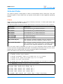
When an ows program prints a 1-Wire slave, it also prints the location of the 1-Wire
slave in the hardware topology. The program can print the information in tree format or
on a single line. Options -dst and -dsl control the formatting.
Here's an example dump of a 1-Wire slave in tree format:
04: USB to 1-Wire (libusb bus 002 ad 005)
01: DS2490
01: 28-0000040CF499-0C DS18B20 thermometer
It says that a DS18B20 1-Wire slave with ROM code 28-0000040CF499-0C is located on
the first channel of the first controller of the fourth adapter.
The same information printed in single line formatting is shown as:
04:01:01
28-0000040CF499-0C
DS18B20 thermometer
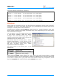
Some ows programs can work with 1-Wire hubs and as such maintain a tree of 1-Wire
slaves, a.k.a. a device tree. These program extend the representation of hardware to
include hubs. For example:
01: USB to 1-Wire (libusb bus 001 ad 002)
01: DS2490
01: 28-0000040CCF80-35 DS18B20 thermometer
01: 81-000000324BBD-31 DS1420 serial ID button
01: EF-000015207600-03 Hobby Boards 4-Channel Hub
02: EF-000015206836-82 Hobby Boards 4-Channel Hub
02: 28-000003F4B4E9-6A DS18B20 thermometer
02: 28-0000040CF499-0C DS18B20 thermometer
04: 26-0000016B4948-00 DS2438 smart battery monitor
02: EF-000015206CCE-4E Hobby Boards 4-Channel Hub
04: 28-0000043F84D2-2C DS18B20 thermometer
The same information printed in single line formatting is shown as:
01:01:01 28-0000040CCF80-35 DS18B20 thermometer
01:01:01 81-000000324BBD-31 DS1420 serial ID button
01:01:01 EF-000015207600-03 Hobby Boards 4-Channel Hub
01:01:01:02 EF-000015206836-82 Hobby Boards 4-Channel Hub
01:01:01:02:02 28-000003F4B4E9-6A DS18B20 thermometer
01:01:01:02:02 28-0000040CF499-0C DS18B20 thermometer
01:01:01:02:04 26-0000016B4948-00 DS2438 smart battery monitor
01:01:01:02 EF-000015206CCE-4E Hobby Boards 4-Channel Hub
01:01:01:02:04 28-0000043F84D2-2C DS18B20 thermometer
The values at the fourth and next positions represent the hub port number. The hub itself
is shown in the preceding line.
User Manual
9
OWS v1.3.2
The ows programs represent a location in the hardware using a specific notation:
adapter:controller:channel[:port]
Each field is a two-digit decimal value starting from one.
The first three values are in fact indexes that refer to the nodes in the topology of the
selected 1-Wire adapters. You can specify option -da to print the topology and the index
values of the various nodes.
Values starting at the fourth position are hub port numbers.
Selecting 1-Wire Adapters
Your system may be connected to many 1-Wire adapters of various kinds. You'll have to
specify which 1-Wire adapters will be used when running an ows program.
The ows programs offer a uniform command line syntax for specifying 1-Wire adapters.
Command line options allow you to specify 1-Wire adapters for specific software
interfaces, like LibUSB or TMEX.
Specify option -da to print the list of 1-Wire adapters that the program will use.
Once the program has established a list of 1-Wire adapters, it creates tasks for the
various controllers that are part of the adapters. The selected channel range may narrow
the creation of the tasks. For example, if you limit the channel range to 5..8, only
controllers that actually have these channels will be assigned a task.
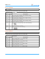
LibUSB
LibUSB provides a platform-independent API for accessing USB devices on various
operating systems.
The ows programs scan for the following USB identifiers:
VID
PID
04FAh 2490h
[1]
REL
any
Device
Maxim DS2490 USB-to-1-Wire chip.[1]
1-Wire adapters DS9490R and DS9490B incorporate this chip.
The following command line arguments control the use of LibUSB:
Option
Description
-lu
Scan all USB devices on all buses.
-lu b
Scan all USB devices on bus b (1..255 decimal).
-lu b ad
Scan USB device with address ad (1..127 decimal) on bus b (1..255
decimal).
-ludbg n
Set the debug level for LibUSB. Value n=0..3 decimal. The default value
is zero.
You've to specify at least one -lu option to tell the program to use LibUSB. The -lu
options are added to a list. The program requests a list of all USB devices with LibUSB
and scans for matching VID/PID/REL values (see table above) while restricting the search
range according to the list.
10
User Manual
OWS v1.3.2
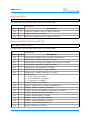
I2C
Pointing to an I2C-to-1-Wire adapter is a two-step process. First you specify the I2C
master. Next you add one or more I2C-to-1-Wire adapters for the specified I2C master.
Note that an I2C master represents a I2C bus that can connect multiple I2C-to-1-Wire
functions.
The following table summarizes all I2C masters known to the ows software. The
availability of each I2C master depends on the architecture of your system:
Option
Description
-i2cdev path Add the i2c-dev path of an I2C master.
-bsc n
Add BSC n (0,1) of a BCM2835 application processor.
-bscdetect
Detect the I2C bus that's present on the GPIO connector of a BCM2835based computer.
Following the I2C option, you can add any number of the following parameters to specify
I2C-to-1-Wire adapters:
Parameters
Description
ds2482 ad
Add a 1-Wire master DS2482 chip at the given I2C address.
abiowire
Add an AbioWire
controllers:
▪ DS2482-800 at
▪ DS2482-800 at
▪ DS2482-100 at
mnu[n]
adapter. This adapter incorporates three 1-Wire
address 24.
address 25.
address 26.
Add an m.nu 1-Wire adapter. Parameter n is optional (0..3). This adapter
incorporates a DS2482-100.
If you specify overlapping I2C devices (devices with the same address) then the program
will display an error message and quit.
Parameters mnu and mnu0 are equal and refer to the m.nu adapter configured for I2C
address 27. This address is in effect when the solder jumpers AD0 and AD1 are open.
Parameters mnu1, mnu2 and mnu3 correspond with I2C address 26, 25, and 24 resp.
Example
Suppose two DS2482 chips are wired to an I2C master that's accessible through i2c-dev
path /dev/i2c-0:
# ./owsenum -i2cdev /dev/i2c-0 ds2482 24 ds2482 25
Both chips will be used for enumeration.
TMEX
The TMEX software is provided by Maxim Integrated and runs on Windows.
Option
-tm t n
Description
Add 1-Wire adapter with port type t (0..15) and port number n (0..15).
You've to specify at least one -tm option to tell the program to use TMEX. The -tm
options are added to a list.
User Manual
11
OWS v1.3.2
The port type corresponds with a hardware interface like USB, the port number
distinguishes between multiple adapters of the same port type. The assignment of port
numbers depends on the port type and is fully controlled by TMEX. For example, -tm 6 1
indicates the USB-to-1-Wire adapter that was plugged in first.
By default these port types are defined:
Port Type
Description
1
DS9097E adapter on serial port.
2
DS1410E adapter on parallel port.
5
DS9097U adapter on serial port.
6
DS9490 adapter on USB.
TMEX is slow. It's advised to use TMEX only for 1-Wire adapters that the ows software
doesn't support, like the DS1410E adapter with parallel port interface.
Serial
To use a serial-to-1-Wire adapter, first you've to specify the serial port, then the adapter
that connects to the serial port. The serial port is identified by a so-called serial path.
Both Linux and Windows support serial paths.
Option
-serial path
Description
Add the path of a serial port.
Following the serial path, you've to specify a serial-to-1-Wire adapter:
Parameters
Description
ds9097u
DS9097U adapter. This adapter has an embedded DS2480B 1-Wire
controller chip. The DTR and RTS lines are wired as a power source for
the chip.
ds2480
DS2480 or DS280B chip.
If you specify ds9097u, the program will set and clear DTR to control the power to the
adapter.
Parameter ds2480 implies a DS2480 or DS280B chip is connected to the serial port
using the TX and RX lines only.
Example
# ./owsenum -serial /dev/ttyS0 ds9097u
This command enumerates all 1-Wire slaves that are connected to the DS9097U adapter
on the first UART.
> owsenum.exe -serial \\.\COM1 ds9097u
This command enumerates all 1-Wire slaves that are connected to the DS9097U adapter
on the first UART. You're advised to use the NT namespace prefix \\.\. See section Serial
Paths more information.
Use of USB-to-serial adapters
You can use a USB-to-serial adapter to hook up a serial-to-1-Wire adapter to your
12
User Manual
OWS v1.3.2
computer.
For example, suppose a DS9097U is connected to a USB-to-serial adapter that resides on
serial path /dev/ttyUSB0. The following command will enumerate all 1-Wire slaves that
are connected to the DS9097U adapter.
# ./owsenum -serial /dev/ttyUSB0 ds9097u
Note that using a USB-to-serial adapter is slower than using an on-board serial port.
Selecting a Range of Channels
When you're controlling one specific 1-Wire slave device, it's advisable to narrow down
the specification of 1-Wire adapters to one specific channel in your physical 1-Wire
topology.
Option
Description
-ch n
Limit all 1-Wire adapters to channel n. Value n=1..8 decimal.
-ch n m
Limit all 1-Wire adapters to channels n to m. Values n,m=1..8 decimal.
The default channel range is 1 to 8.
Example
Suppose you're working with a 1-Wire RGB controller with ROM code 29-00000011CEE10A. The 1-Wire device is connected to channel 5 of the second 1-Wire controller of an
AbioWire adapter. The AbioWire is plugged onto a Raspberry Pi.
# ./owrgbctrl -bscdetect ds2482 25 -ch 5 -id 29-11CEE1 -bo 50 -ro 20 -go 5
If successful, this command will put the RGB controller's output channels to (50;20;5).
Maximal Number of Concurrent Tasks
Normally when you run an ows program, it will execute all tasks concurrently to improve
performance. You can change this behavior on the command line.
Option
-mt n
Description
Set the maximal number of concurrent tasks to n (0, 1..255). Value zero
means unlimited, thus all tasks will be run concurrently. The default
value is zero.
Obviously the program will perform best when -mt is set to zero.
Option -mt provides useful features:
▪
Troubleshooting a situation in Linux on a BCM2835-based computer where LibUSB
reports error 4008.
▪
Improved deterministic behavior. If you're noticing non-deterministic behavior with
multiple concurrent tasks and you prefer to avoid this, you can specify -mt 1 to
confine the execution of tasks to one-by-one. For example, if you run owsenum in
verbose mode using multiple 1-Wire adapters, you may see a different enumeration
order of 1-Wire slaves each time you run the program. If you prefer the same order
each time you run the program, add -mt 1.
User Manual
13
OWS v1.3.2
Dumping Information
The programs offer a set of options for controlling the way information is written to
standard output.
Option
Description
-h
Dump help and exit the program.
-v
Verbose mode.
-da
Dump all 1-Wire adapters in detailed tree format before executing the
main tasks of the program.
-dsl
Output information about a 1-Wire slave on a single line.
-dst
Output information about a 1-Wire slave in tree format. The 1-Wire slave
is displayed as part of an adapter. This setting is the default.
Verbose mode -v is useful for troubleshooting, for example, if you want to see which 1Wire adapters are taken into account.
Arguments -dsl and -dst are opposites.
14
User Manual
OWS v1.3.2
7 Program owsenum
This program is an enumeration tool. It enumerates 1-Wire slaves that are connected to
the selected 1-Wire adapters.
Command Line
Besides the common options, the program offers the following options:
Option
Description
-hub
Enumerate all 1-Wire slaves hierarchically throughout hubs.
-alarm
Enumerate 1-Wire slaves with the alarm flag set.
-family x
Enumerate 1-Wire slaves with family code x (00..FF, hexadecimal).
-topo f
Write the enumeration results to topology file f using the default
encoding.
-topo f enc
Write the enumeration results to topology file f using encoding enc. The
encoding field can be one of the following: utf8, utf16le, utf16be.
If option -hub is specified, the program will enumerate all 1-Wire slaves hierarchically
throughout hubs. If the option is not specified, the program will enumerate the 1-Wire
slaves as they appear on the bus depending on the current state of each hub.
Note that the program will alter the state of the hub ports if option -hub is specified. If
this is not your intention, don't use the option.
Option -alarm tells the program to use the Alarm Search (ECh) command rather than
the Search ROM (F0h) command for enumeration.
You can confine the enumeration of 1-Wire slaves to a specific device family with option
-family.
If -topo is specified, the program will write a topology file that contains a description of
all enumerated 1-Wire networks. The topology file is a Unicode text file. The default
encoding depends on the target system. You can specify an encoding to overrule the
default one.
A topology file generated by program owsenum is typically fed to program owsrds.
Hubs
The program supports the following 1-Wire hubs:
▪
Hobby Boards 4-Channel Hub.
▪
Maxim DS2409 MicroLAN coupler. This chip is used in various hubs:
▪
Hobby Boards 6-channel hub (contains three DS2409 chips).
Hobby Boards 4-Channel Hub
This hub has four ports. Each port can be independently turned on or off. The hub can act
as a power injector.
The family code of the hub is EFh. The device type within this family is 05h.
User Manual
15
OWS v1.3.2
DS2409
The DS2409 chip provides two ports called MAIN and AUX. The ows software designates
MAIN as port 1 and AUX as port 2.
Devices like the Hobby Boards 6-channel hub incorporate multiple DS2409 chips that are
connected in parallel to the same 1-Wire bus. Although such hubs may number the MAIN
and AUX ports in ascending order on the PCB or the case, software has no means to
determine this numbering. Instead software will assume the order produced by the
enumeration algorithms and ultimately the ROM codes of the various DS2409 chips will
determine this order.
For example, when program owsenum is enumerating a 6-channel hub from Hobby
Boards, the status LEDs may turn on and off in an unexpected sequence.
The DS2409 chip offers command for speeding up the enumeration process. The program
takes advantage of these commands.
The family code of the DS2409 is 1Fh.
Program Exit Status
If the program executed successfully, it returns zero, else it returns -1.
Example Invocations of the Program
# ./owsenum -lu
This command will enumerate the 1-Wire slaves found on all USB-to-1-Wire adapters.
# ./owsenum -lu -hub
This command will enumerate 1-Wire slaves hierarchically throughout hubs found on all
USB-to-1-Wire adapters.
# ./owsenum -i2cdev /dev/i2c-1 ds2482 24 -ch 5 8
This command will enumerate the 1-Wire slaves found on channels 5 to 8 of the DS2482800 chip at I2C address 24 on I2C bus /dev/i2c-1.
# ./owsenum -lu -family 28
This command will enumerate members of the DS18B20 family. Note that 28 is an
hexadecimal value.
# ./owsenum -bscdetect abiowire -hub -topo mynetworks.txt
This command will enumerate all controllers and channels on an AbioWire and write the
resulting information to a topology file named mynetworks.txt.
16
User Manual
OWS v1.3.2
8 Program owsprobe
With this program you can locate a specific 1-Wire slave device on the selected 1-Wire
adapters.
Command Line
Besides the common options, the program offers the following options:
Option
-id n
Description
Identifier of the 1-Wire slave. Field n is formatted in either of the
following ways:
▪ xx-xxxxxxxxxxxx: Family code, serial. The CRC will be calculated.
▪ xx-xxxxxxxxxxxx-xx: Family code, serial, CRC. You specify a full ROM
code.
All x are hexadecimal digits. Leading zeroes can be omitted.
Program Exit Status
If the program executed successfully, it returns zero, else it returns -1.
Example Invocations of the Program
# ./owsprobe -lu -id 29-11CEE1
This command searches for the given 1-Wire slave identifier on all available USB-to-1Wire adapters.
User Manual
17
OWS v1.3.2
9 Program owrgbctrl
This program controls the Axiris 1-Wire RGB Controller device.
Command Line
Besides the common options, the program offers the following options:
Option
Description
-id n
Identifier of the 1-Wire slave. Field n is formatted in either of the
following ways:
▪ xx-xxxxxxxxxxxx: Family code, serial. The CRC will be calculated.
▪ xx-xxxxxxxxxxxx-xx: Family code, serial, CRC. You specify a full ROM
code.
All x are hexadecimal digits. Leading zeroes can be omitted.
-pr
Probe the ROM code first.
-c
Clear all registers.
-ro n
Enable the red channel and set the ON period to n (0..255).
-go n
Enable the green channel and set the ON period to n (0..255).
-bo n
Enable the blue channel and set the ON period to n (0..255).
-re
Enable the red channel.
-ge
Enable the green channel.
-be
Enable the blue channel.
-rd
Disable the red channel.
-gd
Disable the green channel.
-bd
Disable the blue channel.
The program's main task is to sends a bundle of commands to the RGB controller. The
various arguments determine which commands will be send. Use -v to print the
commands to standard output.
If -pr is specified, the program will first probe the ROM code on the selected 1-Wire
adapters. If probed successfully, the program knows the location of the 1-Wire RGB
Controller and the program will execute its main task for that location.
If -pr is not specified, the program will execute its main task for all controllers of the
selected 1-Wire adapters.
Specify -v to see the actual command bytes that are written to the RGB controller.
Program Exit Status
If the program executed successfully, it returns zero, else it returns -1.
18
User Manual
OWS v1.3.2
Example Invocations of the Program
> owrgbctrl.exe -lu -id 29-11CEE1 -c
This command clears all internal registers of the target 1-Wire RGB controller.
> owrgbctrl.exe -lu -id 29-11CEE1 -ro 50 -go 20 -bo 80
This command clears sets the internal RGB registers of the target 1-Wire RGB controller
to (50;20;80).
User Manual
19
OWS v1.3.2
10Program owswitch
This program controls the Axiris 1-Wire Mains Switch device.
Command Line
Besides the common options, the program offers the following options:
Option
Description
-id n
Identifier of the 1-Wire slave. Field n is formatted in either of the
following ways:
▪ xx-xxxxxxxxxxxx: Family code, serial. The CRC will be calculated.
▪ xx-xxxxxxxxxxxx-xx: Family code, serial, CRC. You specify a full ROM
code.
All x are hexadecimal digits. Leading zeroes can be omitted.
-pr
Probe the ROM code first.
-on
Turn the mains switch on.
-off
Turn the mains switch off.
The program's main task is to turn on or turn off the switch.
If -pr is specified, the program will first probe the ROM code on the selected 1-Wire
adapters. If probed successfully, the program knows the location of the 1-Wire Mains
Switch and the program will execute its main task for that location.
If -pr is not specified, the program will execute its main task for all controllers of the
selected 1-Wire adapters.
Program Exit Status
If the program executed successfully, it returns zero, else it returns -1.
Example Invocations of the Program
# ./owswitch -i2cdev /dev/i2c-0 ds2482 24 -ch 7 -id 12-A220A8 -on
This command turns on the switch. The device is supposed to be connected to channel 7
of the DS2482-800 chip.
> owswitch.exe -lu -pr -id 12-A220A8 -off
This command probes the 1-Wire Mains Switch on all USB-to-1-Wire adapters. If found,
the program turns off the switch.
20
User Manual
OWS v1.3.2
11 Program owhbh4
This program controls the Hobby Boards 4-Channel Hub.
Command Line
Besides the common options, the program offers the following options:
Option
Description
-id n
Identifier of the 1-Wire slave. Field n is formatted in either of the
following ways:
▪ xx-xxxxxxxxxxxx: Family code, serial. The CRC will be calculated.
▪ xx-xxxxxxxxxxxx-xx: Family code, serial, CRC. You specify a full ROM
code.
All x are hexadecimal digits. Leading zeroes can be omitted.
-pr
Probe the ROM code first.
-setcfg mode Set the channel mode. Field mode can be one of the following:
▪ m: Select multichannel mode.
▪ s: Select single-channel mode.
-setch
on| Turn on or off any of the given channels. You've to specify either on or off
off [1|2|3|4] followed by one or more channel values.
-info
Query information.
The program's main task is to configure the hub, to activate and deactivate the hub's
channels, and to query information.
The Hobby Board devices allocate family code EF (hexadecimal) and provide a command
to read the type of device. The program will always check the type and make sure the
device is a 4-channel hub.
If -pr is specified, the program will first probe the ROM code on the selected 1-Wire
adapters. If probed successfully, the program knows the location of the 1-Wire slave and
the program will execute its main task for that location.
If -pr is not specified, the program will execute its main task for all controllers of the
selected 1-Wire adapters.
When multiple of the following commands are specified, they're executed in this order:
-setcfg ► -setch ► -info
Program Exit Status
If the program executed successfully, it returns zero, else it returns -1.
Example Invocations of the Program
# ./owhbh4 -lu 001 010 -id EF-15207BA3 -info
This command dumps all accessible information of the hub connected to the USB-to-1Wire adapter with USB address 10 sitting on bus 1.
User Manual
21
OWS v1.3.2
# ./owhbh4 -v -pr -lu -id EF-15207BA3 -info -setch on 2 4 -setcfg m
This command does the following work:
1. It looks for (probes) the 4-channel hub with the given ROM code on all detected USBto-1-Wire adapters. If not found, the program stops.
2. It set the hub's configuration to multichannel mode.
3. It turns on channels 2 and 4.
4. It dumps all accessible information.
22
User Manual
OWS v1.3.2
12Program owsmlc
This program controls the Maxim DS2409 MicroLAN Coupler.
Command Line
Besides the common options, the program offers the following options:
Option
Description
-id n
Identifier of the 1-Wire slave. Field n is formatted in either of the
following ways:
▪ xx-xxxxxxxxxxxx: Family code, serial. The CRC will be calculated.
▪ xx-xxxxxxxxxxxx-xx: Family code, serial, CRC. You specify a full ROM
code.
All x are hexadecimal digits. Leading zeroes can be omitted.
-pr
Probe the ROM code first.
-st
Read status. This is the default action. It can also be combined with one
of the control commands to read status back after a control command
has completed.
-disch
Discharge.
-dmain
Direct-on main channel.
-main
Smart-on main channel.
-aux
Smart-on auxiliary channel.
-off
Turn off the active channel.
-cout main
Associate the control output with the main channel.
-cout aux
Associate the control output with the auxiliary channel.
-cout on
Turn on the control output.
-cout off
Turn off the control output.
The program's main task is to activate and deactivate the main channel and the auxiliary
channel, to manipulate the control output pin, and to read the status.
If -pr is specified, the program will first probe the ROM code on the selected 1-Wire
adapters. If probed successfully, the program knows the location of the 1-Wire slave and
the program will execute its main task for that location.
If -pr is not specified, the program will execute its main task for all controllers of the
selected 1-Wire adapters.
Options -disch, -dmain, -main, -aux, -off, and -cout each start a control command.
You can start one control command. If you combine a control command with option -st
then the program will read the status after the control command has completed.
If neither a control command or the read status command is specified, the program will
simply read and print the status of the coupler.
User Manual
23
OWS v1.3.2
NOTE
If you use the program to read status only and you don't specify option -pr, then the
program will always output the status even if the MicroLAN coupler isn't present on the
1-Wire bus. If the device is not present, all status flags will be logic one.
The reason is the DS2409 chip doesn't provide a way to check the validity of the
outcome of the read status command in case the device isn't present on the 1-Wire bus.
In a situation where you're working with multiple adapters and/or multiple channels,
you'll see a status report for each channel.
Program Exit Status
If the program executed successfully, it returns zero, else it returns -1.
Example Invocations of the Program
# ./owsmlc -lu -id 1F-871FE
This command reads the status from the the MicroLAN coupler and prints the
information.
# ./owsmlc -v -pr -lu -id 1F-871FE -main
This command looks for (probes) the MicroLAN coupler with the given ROM code on all
detected USB-to-1-Wire adapters. If found, the program activates the main channel.
# ./owsmlc -v -pr -lu -id 1F-871FE -st
This command does the same as the previous command with the addition the that it
reads and prints the status after the main channel has been activated.
24
User Manual
OWS v1.3.2
13Program owspio
This programs allows you to work with the programmable I/O channels (PIO) of 1-Wire
devices. You can sense the state, set the output level, and monitor the activity flag of
PIO channels (pins).
Command Line
Besides the common options, the program offers the following options:
Option
Description
-id n
Identifier of the 1-Wire slave. Field n is formatted in either of the
following ways:
▪ xx-xxxxxxxxxxxx: Family code, serial. The CRC will be calculated.
▪ xx-xxxxxxxxxxxx-xx: Family code, serial, CRC. You specify a full ROM
code.
All x are hexadecimal digits. Leading zeroes can be omitted.
-pr
Probe the ROM code first.
-off [1|...|8] Turn off the specified channels.
-on [1|...|8]
Turn on the specified channels.
-read
Read the PIO channels once. This is the default behavior.
-read n
Read the PIO channels n times. 0 means infinite times, 1.. means finite
times, default value is 1.
-read n ms
Read the PIO channels n times with ms interval. 0 means infinite times,
1.. means finite times, default value is 0. The interval is specified in
milliseconds, value 1..3600000, default value is 1000.
-rstz s|r
DS2408: Configure the RSTZ pin as STRB output (s) or RST input (r).
The program's main task is to turn on and off the specified PIO channels and read back
once or periodically the state of a chip's PIO channels.
If -pr is specified, the program will first probe the ROM code on the selected 1-Wire
adapters. If probed successfully, the program knows the location of the 1-Wire slave and
the program will execute its main task for that location.
If -pr is not specified, the program will execute its main task for all controllers of the
selected 1-Wire adapters.
Option -off specifies the PIO channels to be turned off (logic zero). Option -on specifies
the PIO channels to be turned on (logic one). If a channel is specified in both -on and
-off options then the -on option takes precedence and the channel will be turned on.
Option -read tells the program to read back the state of the chip's PIO channels. The
outcome depends on the type of 1-Wire slave you've specified in option -id.
Option -read takes two optional parameters. The first parameter is the number of times
to read. The second parameter is the interval in milliseconds in-between two read
operations.
Option -rstz is specific to the DS2408 chip. It enables you to configure the RSTZ pin as
STRB output or RST input.
User Manual
25
OWS v1.3.2
If option -rstz is combined with option -on and/or option -off, the program will first
configure the RSTZ pin.
1-Wire Devices
The program supports the following 1-Wire devices with PIO:
Family
Code
PIO
Channels
DS2406/2407 1Kb EPROM dual switch
12h
1 or 2
DS2408 8-channel addressable switch
29h
8
DS2760/DS2761/DS2762 Li+ battery monitor
30h
1
DS2413 dual-channel addressable switch
3Ah
2
1-Wire Device
Program Exit Status
If the program executed successfully, it returns zero, else it returns -1.
Example Invocations of the Program
# ./owspio -lu -id 29-11CEE1
This command reads the state of the PIO channels from the DS2408 chip.
# ./owspio -lu -id 29-11CEE1 -on 4 6 -off 2 7 -rstz s
This command first configures the RSTZ pin of the DS2408, then it sets the state of the
PIO channels according to the -on and -off options.
26
User Manual
OWS v1.3.2
14Program owsrds
This program reads 1-Wire sensor devices.
Command Line
Besides the common options, the program offers the following options:
Option
Description
-network [n] Add a network directly from the command line. You can specify a branch
of 1-Wire slaves but not a tree hierarchy using hubs this way. Use a
topology file to reach the latter goal.
Field n is formatted in either of the following ways:
▪ xx-xxxxxxxxxxxx: Family code, serial. The CRC will be calculated.
▪ xx-xxxxxxxxxxxx-xx: Family code, serial, CRC. You specify a full ROM
code.
All x are hexadecimal digits. Leading zeroes can be omitted.
If you opt to specify a CRC and it's wrong, the program reports an error
and quits.
-topo f
Read the topology file f and add the resulting networks.
-nid n
Detect up to n non-identification chip devices per network. Value
n=1..255 decimal. The default value is 1.
-tc
Show temperatures in Celsius. This is the default setting.
-tf
Show temperatures in Fahrenheit.
-tk
Show temperatures in Kelvin.
The program's main task is twofold:
1. To associate a set of 1-Wire networks with the specified 1-Wire adapters.
2. To read all 1-Wire sensor devices.
Both options -network and -topo can be specified multiple times. You use these options
to build a list of networks.
A network is not associated with a physical 1-Wire bus. Instead your task is to provide a
set of networks and let program owsrds discover the physical location of each network.
Before the program starts discovering the various networks, it sorts the devices in the
top-level branch of each network. Identification chips are moved to the beginning of the
branch followed by all other 1-Wire slave devices. The resulting devices in the top-level
branch will be ordered as follows:
1. 1-Wire slaves with family code 01h. These identification chips are typically used to tag
a network.
2. 1-Wire slaves with family code 81h. These identification chips occur in 1-Wire adapters
like the DS9490R.
3. All other 1-Wire slaves.
In order to discover a network, the program probes the devices in the top-level branch of
a network on the available 1-Wire buses. Devices behind hubs are not eligible for the
discovery procedure.
User Manual
27
OWS v1.3.2
The devices are probed in the order they were sorted. As soon as one device is detected,
the network is deemed discovered.
All identification chip devices are used for probing. If none is detected, the program
probes a number of non-identification chip devices as specified by option -nid. So, if a
network can't be discovered based on its identification chip device(s), it may still be
discovered based on one of the other devices like a sensor or a hub, providing that -nid
is non-zero.
If option -nid is set to zero, the program will only use identification chip devices during
the discovery procedure.
When a network is detected on a 1-Wire bus, the bus will be excluded from further
detection of other, undiscovered networks. Hence there's a one-to-one relation between a
1-Wire bus and a network.
After a network has been discovered, the corresponding task will start the sense
procedure. This step involves reading all known sensor devices that are part of the
network.
Specify option -v to see the various steps the program is executing. The verbose output
of this program is rather elaborate.
Program behavior with respect to 1-Wire hubs:
▪
During the discovery procedure, the program doesn't access any hubs. This means at
this point in the execution of the program if any hub ports are active the program will
consider the visible subbranches on 1-Wire bus as the top-level branch.
▪
During the sense procedure, the program activates and deactivates hub ports whilst
iterating the device tree. The program however doesn't initialize any hubs or hub
ports to any state before iterating the device tree. This behavior is contrary to the
behavior of program owsenum which will execute a fully deterministic run over the
available hubs by first deactivating all ports before activating the first port.
Program Output
The program outputs a stream of bytes that encode 7-bit ASCII characters (subset of
UTF-8 encoding). This document represents the characters as Unicode.
The program outputs sense data in a consistent manner. Even with option -v enabled,
the sense data can be indiscriminately filtered from the verbose output. Here's an
example output from program owsrds:
[DS18B20
[DS18B20
[DS2438
[DS18S20
[DS18B20
[DS2406
[DS2423
[DS18B20
[DS1822
[DS2413
]
]
]
]
]
]
]
]
]
]
28-000003F4B4E9-6A
28-0000040CF499-0C
26-0000016B4948-00
10-000802A49A17-B1
28-0000043F84D2-2C
12-000000974696-90
1D-0000000DAC01-7B
28-0000040CF2DE-60
22-0000003201DA-1C
3A-000000052F6A-85
2014-02-01
2014-02-01
2014-02-01
2014-02-01
2014-02-01
2014-02-01
2014-02-01
2014-02-01
2014-02-01
2014-02-01
18:15:09
18:15:10
18:15:11
18:15:12
18:15:13
18:15:13
18:15:13
18:15:14
18:15:15
18:15:15
01BC +027.8 C parasite
01BF +027.9 C parasite
0344 +026.1 C 00D9 02.17 V 01FE 05.10 V
0035 +026.5 C external
01AB +026.7 C parasite
0 0 1 1 1 1 2 parasite
0000000061 0000000020
01AF +026.9 C parasite
01BF +027.9 C parasite
0 0 1 1
You can feed the sense data to another process that parses the information. The
formatting is such that the sense data can be parsed without the need for a tokenizer.
The lines with sense data start with a [ character. Software can scan for this character as
28
User Manual
OWS v1.3.2
a unique identifier for a line with sense data outputted by program owsrds.
Each line of sense data starts with a common part:
Offset Length
Description
+00
1
Left square bracket character (U+005B).
+01
10
+11
1
Right square bracket character (U+005D).
+12
1
A space character (U+0020).
+13
2
ROM code: Family code (00..FF, hexadecimal).
+15
1
ROM code: A hyphen (minus) character (U+002D).
+16
12
+28
1
ROM code: A hyphen character (U+002D).
+29
2
ROM code: CRC value (00..FF, hexadecimal).
+31
1
A space character (U+0020).
+32
4
Date: Year (4 digits, decimal).
+36
1
Date: A hyphen (minus) character (U+002D).
+37
2
Date: Month (01..12, decimal).
+39
1
Date: A hyphen (minus) character (U+002D).
+40
2
Date: Day (01..31, decimal).
+42
1
A space character (U+0020).
+43
2
Time: Hour (00..23, decimal).
+45
1
Time: A colon character (U+003A).
+46
2
Time: Minute (00..59, decimal).
+48
1
Time: A colon character (U+003A).
+49
2
Time: Second (00..59, decimal).
+51
1
A space character (U+0020).
Identification of the 1-Wire slave. Padded with space characters
(U+0020) if needed.
ROM code: The serial number (12 digits, hexadecimal).
The formatting of the remainder of the line is subject to the type of 1-Wire slave.
User Manual
29
OWS v1.3.2
Temperature Sensors
[DS18B20
] 28-0000040CF2DE-60 2014-02-01 18:15:14 01AF +026.9 C parasite
If a bus error occurs an invalid temperature register value may have been transferred:
[DS18B20
] 28-0000040CF499-0C 2014-02-01 20:18:28 8052 -------- parasite
The gray text is the common part of the line of sense data.
Identification DS18S20
DS1822
DS18B20
Offset Length
Description
+52
4
Temperature: Register value (4 digits, hexadecimal).
+56
1
Temperature: A space character (U+0020).
+57
8
Temperature: The register value is valid:
+57
1
Temperature: Plus sign (U+002B) or minus sign (U+002D).
+58
3
Temperature: Mantissa (3 digits, decimal).
+61
1
Temperature: Decimal point (U+002E).
+62
1
Temperature: Fraction (1 digit, decimal).
+63
1
Temperature: A space character (U+0020).
+64
1
Temperature:
▪ 'C' for Celsius (U+0043).
▪ 'F' for Fahrenheit (U+0046).
▪ 'K' for Kelvin (U+004B).
+57
8
+57
Temperature: The register value is invalid:
8
Temperature: Line of hyphen characters (U+002D).
+65
1
A space character (U+0020).
+66
8
Power mode. One of the following:
▪ external
▪ parasite
The register value is deemed valid when it's representation in the selected temperature
scale fits in the output format. In a nutshell, if the absolute temperature value is 999.9 or
less it's considered valid, else the program considers it invalid and outputs a dashed line
made up of hyphen characters.
30
User Manual
OWS v1.3.2
Maxim DS2438
[DS2438
05.10 V
] 26-0000016B4948-00 2014-02-01 18:15:11 0344 +026.1 C 00D9 02.17 V 01FE
If a bus error occurs one or both voltage register values may be invalid. The temperature
register value is always valid.
[DS2438
-------
] 26-0000016B4948-00 2014-02-01 18:15:11 0344 +026.1 C 00D9 ------- 01FE
The gray text is the common part of the line of sense data.
Identification DS2438
Offset Length
Description
+52
4
Temperature: Register value (4 digits, hexadecimal).
+56
1
Temperature: A space character (U+0020).
+57
1
Temperature: Plus sign (U+002B) or minus sign (U+002D).
+58
3
Temperature: Mantissa (3 digits, decimal).
+61
1
Temperature: Decimal point (U+002E).
+62
1
Temperature: Fraction (1 digit, decimal).
+63
1
Temperature: A space character (U+0020).
+64
1
Temperature:
▪ 'C' for Celsius (U+0043).
▪ 'F' for Fahrenheit (U+0046).
▪ 'K' for Kelvin (U+004B).
+65
1
A space character (U+0020).
+66
4
VAD: Register value (4 digits, hexadecimal).
+70
1
VAD: A space character (U+0020).
+71
7
VAD: The register value is valid:
+71
2
VAD: Mantissa (2 digits, decimal).
+73
1
VAD: Decimal point (U+002E).
+74
2
VAD: Fraction (2 digits, decimal).
+76
1
VAD: A space character (U+0020).
+77
1
VAD: 'V' for Voltage (U+0043).
+71
7
+71
VAD: The register value is invalid:
7
VAD: Line of hyphen characters (U+002D).
+78
1
A space character (U+0020).
+79
4
VDD: Register value (4 digits, hexadecimal).
+83
1
VDD: A space character (U+0020).
+84
7
VDD: The register value is valid:
+84
User Manual
2
VDD: Mantissa (2 digits, decimal).
31
OWS v1.3.2
+86
1
VDD: Decimal point (U+002E).
+87
2
VDD: Fraction (2 digits, decimal).
+89
1
VDD: A space character (U+0020).
+90
1
VDD: 'V' for Voltage (U+0043).
+84
7
+84
VDD: The register value is invalid:
7
VDD: Line of hyphen characters (U+002D).
Maxim DS2406
[DS2406
] 12-000000974696-90 2014-02-01 18:15:13 0 0 1 1 1 1 2 parasite
The gray text is the common part of the line of sense data.
Identification DS2406
Offset Length
Description
+52
1
PIO-A sensed state: 0 or 1 (binary digit).
+53
1
A space character (U+0020).
+54
1
PIO-B sensed state:
▪ PIO-B is present: 0 or 1 (binary digit).
▪ PIO-B is not present: hyphen character (U+002D).
+55
1
A space character (U+0020).
+56
1
PIO-A output state: 0 or 1 (binary digit).
+57
1
A space character (U+0020).
+58
1
PIO-B output state:
▪ PIO-B is present: 0 or 1 (binary digit).
▪ PIO-B is not present: hyphen character (U+002D).
+59
1
A space character (U+0020).
+60
1
PIO-A activity state: 0 or 1 (binary digit).
+61
1
A space character (U+0020).
+62
1
PIO-B activity state:
▪ PIO-B is present: 0 or 1 (binary digit).
▪ PIO-B is not present: hyphen character (U+002D).
+63
1
A space character (U+0020).
+64
1
PIO pin count: 1 or 2 (decimal digit). PIO-B is present if this value is
set to 2. PIO-A is always present.
+65
1
A space character (U+0020).
+66
8
Power mode. One of the following:
▪ external
▪ parasite
32
User Manual
OWS v1.3.2
Maxim DS2408
[DS2408
] 29-00000011CEE1-0A 2014-02-01 18:15:10 00000000 00010110 00000000
reset external
The gray text is the common part of the line of sense data.
Identification DS2408
Offset Length
Description
+52
8
PIO sensed state: Register value (8 digits, binary).
+60
1
A space character (U+0020).
+61
8
PIO output state: Register value (8 digits, binary).
+69
1
A space character (U+0020).
+70
8
PIO activity state: Register value (8 digits, binary).
+78
1
A space character (U+0020).
+79
6
Configuration of the RSTZ pin. One of the following:
▪ reset
▪ strobe
+85
1
A space character (U+0020).
+86
8
Power mode. One of the following:
▪ external
▪ parasite
Maxim DS2413
[DS2413
] 3A-000000052F6A-85 2014-02-01 18:15:15 0 0 1 1
The gray text is the common part of the line of sense data.
Identification DS2413
Offset Length
Description
+52
1
PIO-A sensed state: 0 or 1 (binary digit).
+53
1
A space character (U+0020).
+54
1
PIO-B sensed state: 0 or 1 (binary digit).
+55
1
A space character (U+0020).
+56
1
PIO-A output state: 0 or 1 (binary digit).
+57
1
A space character (U+0020).
+58
1
PIO-B output state: 0 or 1 (binary digit).
User Manual
33
OWS v1.3.2
Maxim DS2423
[DS2423
] 1D-0000000DAC01-7B 2014-02-01 18:15:13 0000000061 0000000020
The gray text is the common part of the line of sense data.
Identification DS2423
Offset Length
+52
10
+62
1
+63
10
Description
Counter A: Register value (10 digits, decimal).
A space character (U+0020).
Counter B: Register value (10 digits, decimal).
Maxim DS2760/DS2761/DS2762
[DS2760 ] 30-000012B5735B-F4 2014-02-01 01:11:28 1680 +022.5 C 7BE0 +4.84 V FFF8
-0001 FFF4 -00012 00 +000 1
The gray text is the common part of the line of sense data.
Identification DS2760
Offset Length
Description
+52
4
Temperature: Register value (4 digits, hexadecimal).
+56
1
Temperature: A space character (U+0020).
+57
1
Temperature: Plus sign (U+002B) or minus sign (U+002D).
+58
3
Temperature: Mantissa (3 digits, decimal).
+61
1
Temperature: Decimal point (U+002E).
+62
1
Temperature: Fraction (1 digit, decimal).
+63
1
Temperature: A space character (U+0020).
+64
1
Temperature:
▪ 'C' for Celsius (U+0043).
▪ 'F' for Fahrenheit (U+0046).
▪ 'K' for Kelvin (U+004B).
+65
1
A space character (U+0020).
+66
4
Voltage: Register value (4 digits, hexadecimal).
+70
1
Voltage: A space character (U+0020).
+71
1
Voltage: Plus sign (U+002B) or minus sign (U+002D).
+72
1
Voltage: Mantissa (2 digits, decimal).
+73
1
Voltage: Decimal point (U+002E).
+74
2
Voltage: Fraction (2 digits, decimal).
+76
1
Voltage: A space character (U+0020).
+77
1
Voltage: 'V' for Voltage (U+0043).
+78
1
A space character (U+0020).
34
User Manual
OWS v1.3.2
+79
4
Current: Register value (4 digits, hexadecimal).
+83
1
Current: A space character (U+0020).
+84
1
Current: Plus sign (U+002B) or minus sign (U+002D).
+85
4
Current: Mantissa (4 digits, decimal).
+89
1
A space character (U+0020).
+90
4
Current accumulator: Register value (4 digits, hexadecimal).
+94
1
Current accumulator: A space character (U+0020).
+95
1
Current accumulator: Plus sign (U+002B) or minus sign (U+002D).
+96
5
Current accumulator: Mantissa (5 digits, decimal).
+101
1
A space character (U+0020).
+102
2
Current offset: Register value (2 digits, hexadecimal).
+104
1
Current offset: A space character (U+0020).
+105
1
Current offset: Plus sign (U+002B) or minus sign (U+002D).
+106
3
Current offset: Mantissa (3 digits, decimal).
+109
1
A space character (U+0020).
+110
1
PIO sensed state: 0 or 1 (binary digit).
Program Exit Status
If the program executed successfully, it returns zero, else it returns -1.
Example Invocations of the Program
# ./owsrds -bscdetect abiowire -topo mynetworks.txt
This command reads topology file mynetworks.txt and tries to discover the containing
networks on the AbioWire.
# ./owsrds -lu -network 28-40CCF80 26-16B4948 -network 28-3F4B4E9 -nid 2
This command defines two networks without any identification chips. The networks are to
be discovered on all available USB-to-1-Wire adapters.
User Manual
35
OWS v1.3.2
15Topology Files
Overview
A topology file describes a number of 1-Wire networks in a human-readable text format.
It's called a topology file because the file describes the topology of 1-Wire networks
which are hierarchical in nature.
Text Encoding
A topology file contains Unicode text. The so-called byte order mark at the start of the
file determines the encoding of the Unicode text. The ows programs supports the
following file encodings:
Byte Order Mark
File Encoding
<none>
UTF-8
EFh BBh BFh
UTF-8
FFh FEh
UTF-16 Little Endian
FEh FFh
UTF-16 Big Endian
Each operating system uses a preferred encoding. This is called the default encoding in
the ows software. An ows program that write topology files will apply the following
default encodings:
▪
Linux: UTF-8.
▪
Windows: UTF-16 Little Endian.
Manual Editing
You can open a topology file with a text editor and modify its contents. If you decide to
go this way, be sure your text editor can cope with Unicode, byte-order marks and file
encodings, else you may end up with a corrupted topology file.
There are several reasons why you would manually edit a topology file:
▪
If you created the topology file with a 1-Wire adapter with built-in identification chip
and you want to use another 1-Wire adapter, you can delete the ROM code of the
identification chip (typically has family code 81h).
▪
If your network incorporates an identification chip (typically has family code 01h) and
you created the topology file with a 1-Wire adapter with built-in identification chip,
then you probably have no use for adapter's identification chip and you can remove
the ROM code.
▪
You made a slight modification to a network but don't want to go through a lengthy
enumeration process again.
▪
You want to copy-paste networks between topology files, split a topology file, or
merge several topology files into one file.
▪
You prefer to create your own file from scratch.
36
User Manual
OWS v1.3.2
Usage
Here's a simple example on how to use topology files. This example assumes you're
using an AbioWire with one or more 1-Wire networks connected.
# ./owsenum -bscdetect abiowire -hub -topo mynetworks.txt
This command enumerates the 1-Wire hub and slaves on all channels of all controllers of
the AbioWire and creates a topology file called mynetworks.txt.
Once the topology file has been created, you can read the sensor devices with the
following command:
# ./owsrds -bscdetect abiowire -topo mynetworks.txt
This command will first detect all networks in the topology file on the available channels
of the AbioWire. For each detected network the program reads the known sensors
devices as they're described in the topology file. If hubs and subbranches are part of the
network, the program will activate and deactivate the necessary hub ports in order to
reach the various sensor devices.
You can reconnect the networks to different channels on the AbioWire. You can even
reconnect them to other 1-Wire adapters. The program always runs a detection
procedure hence an explicit binding between a network and a 1-Wire channel doesn't
exist.
If you change the topology of a specific network (add a sensor device, reconnect a
subbranch to a different hub port, …) then you'll have to regenerate or manually edit the
topology file to reflect the new situation on the network.
Contents
Let's get started with a topology file for an example network. The topology file is created
by program owsenum in Linux:
# ./owsenum -lu -hub -topo home.txt utf8
Suppose the network is connected to a DS9490R USB-to-1-Wire adapter and its topology
is as the enumeration program outputs:
01: USB to 1-Wire (libusb bus 001 ad 002)
01: DS2490
01: 28-0000040CF2DE-60 DS18B20 thermometer
01: 01-000016707B77-0E DS2401/2411/1990A silicon serial number
01: 81-000000324BBD-31 DS1420 serial ID button
01: EF-000015207600-03 Hobby Boards 4-Channel Hub
01: EF-000015206836-82 Hobby Boards 4-Channel Hub
02: 26-0000016B4948-00 DS2438 smart battery monitor
03: 10-000802A49A17-B1 DS18S20/1920 thermometer
03: 28-0000043F84D2-2C DS18B20 thermometer
04: 28-000003F4B4E9-6A DS18B20 thermometer
04: 28-0000040CF499-0C DS18B20 thermometer
02: 28-0000040CCF80-35 DS18B20 thermometer
02: 22-0000003201DA-1C DS1822 Econo digital thermometer
User Manual
37
OWS v1.3.2
Let's take a closer look at this particular network:
▪
There are two hubs, one connected to a port of the other one. This connection
scheme adds two levels to the device tree.
▪
The network feature its own identification chip (family code 01h). The chip is location
in the top-level branch of the network.
▪
The identification chip with family code 81h is part of the DS9490R USB-to-1-Wire
adapter.
▪
The other 1-Wire slaves are temperature sensors of various types.
The enumeration program creates topology file home.txt encoded as UTF-8. The file
contains the following text:
# ows topology file
#
# Encoding: UTF-8
#
# Created: 2014/02/01 18:01:48
port 3
{
"10-000802A49A17"
"28-0000043F84D2"
}
network
{
"28-0000040CF2DE" .
"01-000016707B77" .
"81-000000324BBD" .
"EF-000015207600" hbh4 .
{
port 1
{
"EF-000015206836" hbh4 .
{
port 2
{
"26-0000016B4948" .
}
port 4
{
"28-000003F4B4E9"
"28-0000040CF499"
}
.
.
.
.
}
}
port 2
{
"28-0000040CCF80"
"22-0000003201DA"
}
.
.
}
}
The file name extension .txt isn't required. You can use any extension you want or none
at all, the software doesn't look for any extension. The .txt extension is used in this
document to denote the topology file contains text and can be edited with a text editor.
The topology file home.txt describes one network. Note that a topology file can
describes any number of networks.
The network label starts the description of a network. The { character (U+007B) must
follow. The } character (U+007D) indicates the end of the network description.
A 1-Wire slave device is defined as a formatted string between two " characters
(U+0022). The string must contain the following elements in the given order:
1. The family code (00..FF, hexadecimal, case-insensitive, leading zeroes are optional).
2. A hyphen (minus) character (U+002D).
3. The serial number (12 digits, hexadecimal, case-insensitive, leading zeroes are
optional).
38
User Manual
OWS v1.3.2
Optional part:
4. A hyphen (minus) character (U+002D).
5. CRC value (00..FF, hexadecimal, case-insensitive, leading zeroes are optional).
If the optional CRC part is specified, the CRC value must be valid.
The string can be followed by one or more labels and must be concluded with a dot
character (U+002E).
The hbh4 label says the 1-Wire slave is a Hobby Boards 4-channel hub. After the dot
character, the description of the hub is expected between a { character (U+007B) and a
} character (U+007D). The label port starts the description of a subbranch of the
network. The label is followed by the port number. After the port number the description
is the same as with the network label.
The ds2409 label indicates the 1-Wire slave is a DS2409 hub chip. If this label isn't
specified, the program will ignore the DS2409 1-Wire slave. The syntax after the dot
character is the same as with the hbh4 label.
User Manual
39
OWS v1.3.2
16Serial Paths
You need to specify a serial path in order to communicate with a serial port. The next
sections explain in more detail how you specify serial paths in each supported operating
system.
Linux
Serial ports are accessible in the device directory structure. A serial path starts with
/dev. A serial path is case-sensitive.
The following table summarizes serial paths that are commonly found on Linux systems:
Serial Path
Serial Port
/dev/ttyS0
The computer's 1st on-board serial port
/dev/ttyS1
The computer's 2nd on-board serial port
/dev/ttyS2
The computer's 3rd on-board serial port
/dev/ttyS3
The computer's 4th on-board serial port
/dev/ttyUSB0
1st USB serial adapter
/dev/ttyUSB1
2nd USB serial adapter
/dev/serial/by-id/
This directory contains symbolic links to serial devices.
Each symbolic link name identifies a specific device.
/dev/serial/by-path/
This directory contains symbolic links to serial devices.
Each symbolic link name represents a hardware path to
the device, like a specific USB port on your computer.
Here are some useful commands you can run to get information about present serial
devices and their corresponding serial path. The following commands were run on a Linux
system with one on-board UART and one connected USB-to-serial adapter.
Filter information from the kernel message buffer:
$ dmesg | grep 'tty'
[
0.000000] console [tty0] enabled
[
0.516785] serial8250: ttyS0 at I/O 0x3f8 (irq = 4) is a 16550A
[
0.517463] 00:0b: ttyS0 at I/O 0x3f8 (irq = 4) is a 16550A
[
0.559097] tty tty55: hash matches
[
66.076326] usb 2-1: FTDI USB Serial Device converter now attached to ttyUSB0
Use the setserial command to produce a list of serial paths:
$ setserial -g /dev/ttyS* /dev/ttyUSB*
/dev/ttyS0, UART: 16550A, Port: 0x03f8, IRQ: 4
/dev/ttyS1, UART: unknown, Port: 0x02f8, IRQ: 3
/dev/ttyS2, UART: unknown, Port: 0x03e8, IRQ: 4
/dev/ttyS3, UART: unknown, Port: 0x02e8, IRQ: 3
/dev/ttyUSB0, UART: unknown, Port: 0x0000, IRQ: 0, Flags: low_latency
40
User Manual
OWS v1.3.2
List serial devices in the device directory:
$ ls -l /dev/ttyS* /dev/ttyUSB*
crw-rw---- 1 root dialout
4, 64 2012-02-22 14:19 /dev/ttyS0
crw-rw---- 1 root dialout
4, 65 2012-02-22 14:19 /dev/ttyS1
crw-rw---- 1 root dialout
4, 66 2012-02-22 14:19 /dev/ttyS2
crw-rw---- 1 root dialout
4, 67 2012-02-22 14:19 /dev/ttyS3
crw-rw---- 1 root dialout 188,
0 2012-02-22 14:20 /dev/ttyUSB0
Windows
Serial ports are accessible through the Win32 device namespace, which is part of the NT
namespace. As such a serial path starts with \\.\ followed by the device name of the
serial port. A serial path is case-insensitive.
A serial port is typically named COM<x> where <x> is a number between 1 and 256.
Other naming schemes may apply and aliases may exist, depending on the serial driver
that controls the serial port.
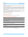
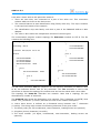
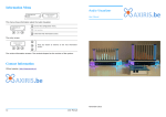
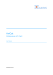
You can obtain a list of available
in the device manager. Open
manager and view devices by
section named Ports (COM & LPT)
available serial and parallel ports.
serial ports
the device
type. The
contains all
The device name of a serial port is shown
between parentheses. In the picture to the
right, you can see two serial ports. COM1 is
the PC's on-board serial port, COM3
represents a USB serial adapter.
The serial paths to the serial ports in the
picture are:
Serial Path
Serial Port
\\.\COM1
Communications Port (COM1)
\\.\COM3
USB Serial Port (COM3)
Serial paths like COM1 (that's without the \\.\ prefix) will work because COM1 to COM9
are reserved names in the NT namespace. COM10 to COM256 aren't reserved names and
you'll have to specify the \\.\ prefix with these device names. By comparison, serial
path \\.\COM100 will work but serial path COM100 won't work.
User Manual
41
OWS v1.3.2
17Troubleshooting
Error 4008 on BCM2835-based Computer
With certain combinations of the LibUSB library and the Linux kernel, LibUSB may
generate error messages and fail USB transfers when the program is working with
multiple USB-to-1-Wire adapters. In this case, you can specify -mt 1 to (hopefully) solve
the problem.
We found one source on the Internet that mentions this problem. The source indicates
the problem can be solved by upgrading to version 3.2.27 or later of the Linux kernel:
http://www.raspberrypi.org/phpBB3/viewtopic.php?t=19393
Please be aware this web link may become unavailable in time due to changes in the web
site.
Program Fails Every Other Time
If you're using a DS9490 USB-to-1-Wire adapter on Windows, you may observe a
situation where an ows program fails every other time you run it.
The reason of this failure is a timeout condition somewhere in LibUSB or a lower-level
driver. For some reason one of the USB transfers scheduled by the program is accepted
but not sent to the USB hardware, leading to the timeout condition.
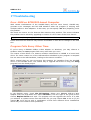
We've noticed that you can circumvent this situation by upgrading from the WinUSB
driver to the libusbK driver. The easiest way to upgrade the driver is using the zadig
program from the libwdi project.
In the Options menu, check List All Devices. Select your DS9490 USB-to-1-Wire
adapter from the drop-down box. Select libusbK in the box right to the green arrow.
Choose Replace Driver and click. The program will now upgrade the driver. If it asks
you whether to replace newer files with older file you may choose Yes to do so (if you
choose No you'll end up with a combination of files from different driver installations
which may in turn lead to other problems).
42
User Manual
OWS v1.3.2
LibUSB and TMEX are Fighting
When you run an ows program in Windows, there's nothing that prevents you from
targeting a 1-Wire master twice. For example:
> owsenum.exe -lu -tm 6 1
Both LibUSB and TMEX will access the same USB-to-1-Wire adapter. By design, TMEX will
get access to the USB device while LibUSB won't.
18Software Design
This section discusses a number of attributes of the design of the ows software.
Threading
Each ows program is single-threaded in its proper context. This means it embodies
single-threaded behavior to the extend of its own implementation. In-process libraries
and the operating system aren't taken into account.
External libraries that are present in the program's process space may create threads for
their own usage. This doesn't influence the single-threaded behavior of the ows
programs.
To accomplish the aforementioned behavior, the ows software follows these rules:
▪
It is fully asynchronous by design.
▪
It employs a fine-grained control mechanism for blocking its main thread.
An important necessity is the availability of asynchronous (non-blocking) mechanisms in
the operating system and external libraries.
LibUSB can be used non-blocking and single-threaded as long as a callback function
invoked by LibUSB doesn't call back into LibUSB.
TMEX is completely synchronous, so it's not really compatible with the design of the ows
software. To circumvent this restriction, the ows software creates a thread for each
TMEX 1-Wire controller and delegates the execution of each 1-Wire bus transaction to
this thread in a serialized, fully deterministic way. As a result, interfacing with TMEX is
rather slow. As such it is advised to use TMEX only for 1-Wire adapters that aren't
directly supported by the ows software.
Libraries
The ows software loads the following libraries dynamically and only when needed:
▪
LibUSB (Linux, Windows).
▪
TMEX (Windows).
This means the ows programs can run without these libraries. However if one of the
libraries isn't installed you won't be able to use its specific functionality. Specify option -v
to see how a program deals with missing libraries.
User Manual
43
OWS v1.3.2
19Software Revision History
Version
Description
1.0.0
▪
Initial release of ows.
1.1.0
▪
Fixed a hang-up while handling multiple 1-Wire channels (owsprobe,
owrgbctrl, owswitch).
Removed unwanted printing.
Added program owhbh4.
▪
▪
1.2.0
▪
▪
▪
▪
▪
▪
1.2.1
▪
▪
▪
▪
▪
Fixed a crash when specifying option -lu in Windows 2000 (all programs).
Added support for DS2423, DS2406, DS2408 (owsrds).
Added representation of temperatures in Fahrenheit (owsrds).
Added representation of temperatures in Kelvin (owsrds).
All temperature values are rounded to the nearest tenths instead of
being truncated (owsrds).
1.2.2
▪
Added support for DS2409 (owsenum, owsrds).
1.3.0
▪
▪
▪
Added program owsmlc.
Added program owspio.
Fixed help text produced by option -h (owsprobe, owswitch).
1.3.1
▪
▪
Added m.nu 1-Wire adapter.
Added support for DS2760, DS2761, DS2762 (owspio, owsrds).
1.3.2
▪
▪
Added reporting of VDD of DS2438 (owsrds).
Add reporting of RSTZ pin configuration and power mode of DS2408
(owsrds).
Fixed a non-deterministic hang situation with LibUSB when the library
was called into from a callback function.
Updated the list of known 1-Wire devices and family codes.
▪
▪
44
Added hierarchical enumeration throughout hubs (owsenum).
Added enumeration of 1-Wire slaves with the alarm flag set (owsenum).
Added enumeration of 1-Wire slaves of a certain family (owsenum).
Fixed bug in setting of single-channel and multichannel mode (owhbh4).
Added program owsrds. Supported sensor devices are DS18S20,
DS1822, DS2438, DS18B20.
Added the concept of the topology file (owsenum, owsrds).
User Manual
OWS v1.3.2
20Software License
The ows software is free of charge ("freeware").
It's allowed to copy or distribute the software providing that you do so with the
distribution in its entirety as described in chapter Distribution. It's forbidden to change
the software or any other files that are part of the distribution.
It's forbidden to sell, rent, or profit from the distribution in its entirety or the software or
any other files that are part of the distribution.
It's allowed to spread the distribution in a packaging format different from the packaging
format provided by Axiris.
21Disclaimer
Axiris products are not designed, authorized or warranted to be suitable for use in space,
nautical, space, military, medical, life-critical or safety-critical devices or equipment.
Axiris products are not designed, authorized or warranted to be suitable for use in
applications where failure or malfunction of an Axiris product can result in personal
injury, death, property damage or environmental damage.
Axiris accepts no liability for inclusion or use of Axiris products in such applications and
such inclusion or use is at the customer's own risk. Should the customer use Axiris
products for such application, the customer shall indemnify and hold Axiris harmless
against all claims and damages.
22Contact Information
Official website: http://www.axiris.eu/
User Manual
45