1
The internal workings of video game consoles:
The GameBoy
John Ernberg
Mälardalen University, IDT
Supervisor: Linus Källberg
Examiner: Lars Asplund
June 1, 2011
Page 2 of 22
Abstract
English: This report describes the process of writing an emulator for the Nintendo
GameBoy hand-held console from 1989 using the documents that are publicly
available. The goal of the project was to get some official cartridge program ROMs to
run on the emulator. A few components like sound had to be skipped due to time
restraints. The solution was done by dividing the task into several stages, bringing in a
new functionality with each stage. I began with the CPU and memory, before moving
on to the PPU/LCD, and finally the joypad. This report also describes how those
components work. The results from running a set of test ROMs indicate that the CPU
instructions are 100% correctly emulated. However, there are some timing issues that
sadly prevents any official cartridge program ROMs from running correctly.
Svenska: Denna rapport beskriver processen för att utveckla en emulator för
Nintendos GameBoy, en handhållen spelkonsol från 1989, med hjälp av de dokument
som finns publikt tillgängliga. Målet med projektet var att få några av de officiella
kassetternas program att köra på emulatorn. En del komponenter så som ljud fick
hoppas över på grund av tidsbrist. Lösningen utfördes genom att dela upp uppgiften i
flera steg, där varje steg införde nya funktionaliteter: Jag började med CPUn och
minnet innan det var dags för PPU/LCD och till sist joypad. Denna rapport beskriver
även hur dessa komponenter fungerar. Resultaten från exekvering av en uppsättning
test-ROMs tyder i alla fall på att CPU:ns instruktioner är 100% korrekt emulerade.
Dock kvarstår några problem med timingen som tyvärr hindrar de officiella
kassetternas program från att köra korrekt.
Page 3 of 22
Table of contents
Abstract.................................................................................................................................................2
Background...........................................................................................................................................4
Purpose.................................................................................................................................................4
Conventions..........................................................................................................................................4
Related work.........................................................................................................................................5
Problem formulation.............................................................................................................................6
Problem analysis and method selection................................................................................................7
CPU..................................................................................................................................................7
RAM................................................................................................................................................7
PPU/LCD.........................................................................................................................................7
Joypad..............................................................................................................................................8
Other models and methods...................................................................................................................9
Re-compiling CPU...........................................................................................................................9
Threading.........................................................................................................................................9
Hacked boot process........................................................................................................................9
Plugin-based.....................................................................................................................................9
Solution...............................................................................................................................................10
Stage 1: The main system..............................................................................................................12
Stage 2: CPU instructions and memory handling..........................................................................12
Stage 3: Interrupts and the HALT state..........................................................................................13
Stage 4: PPU and basic LCD functionality....................................................................................14
Stage 5: Sprites and DMA transfers...............................................................................................15
Stage 6: The joypad.......................................................................................................................16
Results................................................................................................................................................17
Analysis of results..............................................................................................................................18
Future work........................................................................................................................................19
Summary and conclusions..................................................................................................................21
References..........................................................................................................................................22
Page 4 of 22
Background
Ever since I started to learn programming in Visual Basic I have been interested in
learning how the code I wrote became runnable in a deeper fashion than knowing that
pressing “run” from the Visual Studio development environment executes my code. As
I started learning the ”better” languages C and C++ I came closer to compilers, how
they work and what they do. The more I discovered, the easier it became to write
good code. Since I am studying to be a game developer and I tend to be more
amused by console games than computer games, I figured I might as well learn how
game consoles work. And here we are.
Purpose
The purpose of this project was to gain an insight into how game consoles work. To
limit this project to a sensible size I had to choose one console, and the modern ones
do not have enough documentation publicly available. So I looked at the older
consoles and I found the hand-held GameBoy console from 1989 by Nintendo to be
the best choice judging from complexity, size and my time frame, that I already
stretched to the double, in order to have a chance to complete this project. The
GameBoy has a whole bunch of games. Unfortunately I do not have a number but I
would not be surprised if a couple of thousand titles existed. To prove that I have
understood the console correctly I was to write an emulator based on what I could
learn. If the emulator worked well and could execute some of the official cartridge
program ROMs my goal would be accomplished.
Conventions
Explanations for abbreviations and ”odd” words that will occur throughout this report:
DMG: The name of the CPU in the GameBoy.
Emulator: A program that mimics a system as close to the real thing as possible.
GLFW: OpenGL FrameWork, a utility library for OpenGL.
HLE: High-Level Emulation. Instead of emulating instructions, the system is emulated
based on hardware tests. HLE can be seen as a type of black-box emulation where
you input data and get other data back. This is rarely an accurate method to do
something as many edge-cases are overlooked.
LLE: Low-Level Emulation, the most accurate method to emulate a system. When
done correctly, this method needs a dump of the processing units' program ROM and
instruction table in order to work. When LLE is implemented correctly it will behave
exactly as the hardware would for every case.
OAM: Object Attribute Memory. Used for sprites.
Opcode: A CPU instruction.
PPU: Pixel Processing Unit, a predecessor to today's Graphical Processing Unit (GPU).
Program ROM: The program ROM is the container of the executable code that exists
on a chip.
RNG: Random number generator.
SPU: Sound Processing Unit.
Page 5 of 22
Related work
Emulators have been developed for a very long time but only recently focus begun to
shift from compatibility (supporting as many games as possible) to accuracy
(mimicking the hardware as closely as possible). The two emulator projects in this
area that are worth mentioning here are Gambatte and bsnes. These two projects
have been working on very similar things. Gambatte is an emulator of the GameBoy
Color, which has backwards compatibility with the original GameBoy that I am looking
at. Gambatte's main objective is to emulate the hardware as accurately as possible
and it does a very good job at that even though there are still portions left to emulate
properly. It is fully functional and most games emulate perfectly. bsnes on the other
hand is a Super Nintendo Entertainment System (SNES) emulator. What makes this
one worth mentioning here is that bsnes has emulation of the Super GameBoy
accessory under development during the time of writing this report. bsnes, just as
Gambatte, is an emulator that aims to be as accurate as possible.
There has also been a lot of work done in order to document the GameBoy's system
and how it works. Most of this documentation exists only as source code in the
mentioned emulator projects but there is also a technical document which was
maintained up until 2001. This document is well known among the emulator
developers and is referred to as the “Pandocs” due to the original author who goes by
the nickname “Pan of -ATX-”, real name unknown. The final maintainer was the author
of the GameBoy emulator NO$GMB (read: no-cash GMB). The reason for his emulator
not being mentioned above is that his emulator aimed more at compatibility than
accuracy and therefore the code in that emulator is not guaranteed to do as the
original GameBoy would in every situation.
Page 6 of 22
Problem formulation
The development of the emulator for the Nintendo GameBoy had to be constrained if
it was to be completed within the time frame. For this to be possible I had to drop a
few things: I chose to drop sound emulation along with cartridge extensions and serial
port emulation, since these are the most time-consuming parts to implement
compared to what they add functionally. While the cartridge extensions make more
games playable they are not really a part of the GameBoy itself, so I chose to emulate
only the GameBoy hardware which does not include these extensions. Also, games
can be played without sound and without support for multiplayer through the serial
connection, but it is a lot harder to play them without the LCD, RAM or CPU. This
limited my project to develop a GameBoy emulator with functioning CPU, RAM,
PPU/LCD, and joypad. Since the GameBoy's screen clocks in at 60 FPS (frames per
second), the emulator must be fast enough to provide the same results. This makes
fast code the key to success if you want to run at full speed. A secondary goal was
therefore to write code that is as optimized as possible without losing readability.
Page 7 of 22
Problem analysis and method selection
The GameBoy is a portable battery-driven video game console released in 1989, so
the system requirements are not that high. The games are stored on exchangeable
cartridges that sometimes also carry expansion chips to provide enhancements that
the GameBoy itself cannot. Here follows a breakdown of all the components of the
GameBoy that needed to be emulated.
CPU
The GameBoy's CPU clocks in at 4 MHz (or 4194304 Hz). This means the CPU will
execute 4194304 cycles per second. It has a 1-byte opcode size and has interrupt
functionality. There are two sets of opcodes: first the normal opcode table, and then
an extended one. All opcodes except those accessing the extended opcode table and
the ones taking immediate operand values are only one byte long. Since most PCs
today run at several GHz I found it possible to meet this requirement with a simple
byte interpreter. This is the oldest method in the book for a reason: it always works.
In general it is not as fast as some of the modern approaches like re-compilers but
with such a slow CPU as the GameBoy's a re-compiler would most likely even be
slower than the interpreter. The interpreter is basically a huge switch statement with a
case for every opcode. Since this CPU also has an extended opcode table, the
emulator needed an additional switch statement for this. When doing an interpreter
solution one also has to take into account the CPU registers and flags. These need to
exist as variables compared to re-compiling where the registers and flags in the target
CPU are used instead.
RAM
For the RAM/Memory there were two obvious choices. The first one was to put it all in
the same array and the second was to divide it into its constituent parts: working
RAM, high RAM, video RAM, OAM, sound wave RAM, and external registers. The first
option is really easy to implement and lets me use the memory map addresses as
index values. The second option on the other hand is trickier to implement but has a
few advantages. Firstly, it will save memory if the entire address range is not used.
Secondly, it is handy if some of the external registers can overflow since the overflow
is easier to check for if the variables representing these registers are made larger. I
had to use the second option because the GameBoy has both of the “requirements”
needed to make the first option impractical to use.
PPU/LCD
In the GameBoy the PPU and the LCD are connected so tightly together that they are
practically the same unit. Based on this fact these two components had to be coupled
tightly together in the solution. Since they are so close in hardware it would not make
sense to split them apart in an emulator, because this would just add unnecessary
overhead. The LCD runs at 60Hz and has a size of 160x144 pixels. The PPU's internal
map is 256x256 pixels, so the entire map cannot fit on screen at once. This is solved
by two external registers controlling where on the map the LCDs top-left corner is
located. The PPU can only be done with HLE because no work has been done on
dumping its program ROM. To represent the LCD I used a combination of OpenGL and
GLFW which is a library much like the more common GLUT, to create windowed
applications, but it gives me control of the main loop. Having control of the main loop
is important when developing emulators because anything that can slow the emulator
down should be eliminated, and not knowing what happens in the main loop can have
dire effects on performance.
Page 8 of 22
Joypad
To emulate the joypad the keyboard was used. A button on the Joypad can be pressed
at any time, so for every machine cycle all events should be polled and processed
accordingly. Even though most games poll input only once per frame, sometimes not
even that frequently, it is not really necessary to poll for input every cycle, but it
would be the most correct thing to do from the accuracy aspect. There is even a
chance that some games use the joypad input in their RNG calculations, and not being
able to influence the RNG in the same way on the emulator as you would be able to on
the real console would not be really accurate at all.
Page 9 of 22
Other models and methods
Re-compiling CPU
The re-compiling CPU method does exactly what it sounds like it would be doing: it
takes the instructions of the emulated CPU and translates them into its own
instructions. One nice side effect of this approach is that the emulated CPU's registers
will also be translated, which means the computer's CPU registers will be used directly
instead of variables when writing the code. While this method adds overhead in the
shape of the re-compiling process it is very efficient for emulating faster CPUs. This
emulation model is used by the GameCube and Wii emulator Dolphin where the
difference between running the interpreter CPU compared to the re-compiling CPU is a
~500% speed increase on my computer (My CPU is an AMD Athlon64 X2 4600+ and I
have 4 GB of RAM).
Threading
Threading can be used to parallelize operations between components where possible,
like when it is feasible letting the CPU begin the processing of the next frame in
advance instead of waiting for the GPU/PPU or SPU to complete its operations.
This is also only used when emulating faster systems as the threading overhead will
otherwise have a bigger impact on performance than the help the threaded
implementation gives. However, to make threading more useful, the developer of
bsnes (see “Related work”), byuu, developed a low-overhead threading library called
libco. Still the GameBoy is not a fast enough system to be helped by threading.
Hacked boot process
This is not as nasty as it sounds. What the hacked boot process does is skipping the
steps of BIOS by just initializing the emulated hardware to the values normally
generated upon a successful boot. This is a very popular approach because the BIOS
does not need to be extracted from the console. Extracting the BIOS often requires
the CPU to be removed from the console circuit board and “decapped”. The
decapsulation process is beyond the scope of this report, but if you as the reader want
to know more there are two web links in the footer with some information.12
Plugin-based
What this does is modularize the emulator even further and in the process make it
more customizable. This design lets the developer implement only the parts that he or
she wants to and leaves the playing field open for others. Another advantage from this
is that if you have an idea on how to make a better GPU/PPU implementation for a
given system, you will not have to write an emulator for the other components first in
order to test your idea. This method is mostly used when there are still a lot of
uncertainties regarding how the hardware in the console actually works. Once that has
been properly figured out this concept is usually dropped because there is less
overhead to not manage DLL plug-ins, and you have better control over all the
components of the emulator.
1 http://uvicrec.blogspot.com/
2 http://siliconcert.com/decap.htm
Page 10 of 22
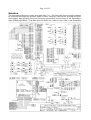
Solution
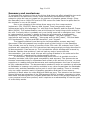
The language selected to solve this task was C++. The task was then solved in stages
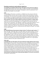
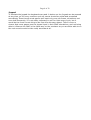
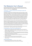
to keep the development process under control. How the code where divided into files
and classes was decided using the following schematics and pictures of the GameBoy's
guts [GBHard][GBAut]. That was done to make the code be more like a real GameBoy.
Page 11 of 22
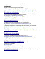
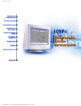
On the LCD circuit board all the components are hidden behind the LCD.
Page 12 of 22
Stage 1: The main system
The main system had to be implemented first because it wraps all the components
together and initializes everything. During this initialization process the window is
created and set up to draw using orthographic projection; since the GameBoy does
not have any 3D capabilities it is unnecessary to have the third dimension enabled.
Here also a small hack is applied which ensures a greater accuracy of the pixel
drawing, i.e. a greater number of pixels will be correctly aligned to the pixel grid. If
the screen creation is successful the initialization will move on and load the cartridge
ROM file that was specified as a parameter during the emulator's launch. If this file is
not found the emulator will shut down with an error. Once the ROM is loaded the
components will be created in the following order: Memory, Joypad, LCD and CPU.
The CPU has to be created last as it needs pointers to each and every one of
the previously mentioned components. This is because everything is enslaved to the
CPU's clock. While the real GameBoy has a global clock called the machine clock the
CPU ticks at a multiple of the rate of the machine clock so nothing is really sacrificed
by using the CPU's clock instead of the machine clock. Also, it makes the
implementation of the CPU a lot easier. The reason for this is that the GameBoy CPU
has instructions that take several machine clock cycles to complete and if the timing
was done using the machine clock the emulated CPU would be running one machine
clock cycle at a time. That would force the implementation to know where in the
opcode it was between machine clock ticks as it would only run one tick at a time.
When the CPU is created by the main system wrapper it also loads the BIOS of
the GameBoy. This BIOS sets up important parts of the memory and verifies the
cartridge ROM by running some sort of validity check. If this check fails the BIOS will
lock up and the GameBoy has to be restarted. The emulator will be shut down if the
BIOS ROM file is not found. Once the initialization is complete the main loop of the
emulator is entered. All this loop does is execute the CPU one instruction at a time
until the emulator is terminated by the user.
Stage 2: CPU instructions and memory handling
The CPU and Memory components of the emulator were developed in parallel as the
CPU relies on the memory to work and mistakes in the memory handling is mostly
found during the development of the CPU. The GameBoy CPU has ten registers: ten 8bit general purpose registers, two special registers used as stack pointer and program
counter, and one flag register. The seven 8-bit registers and the flag register can be
paired up to form four 16-bit registers. This was emulated by forming unions of the
two 8-bit registers that could become a pair for every register, as demonstrated by the
following line of code:
union { uint16_t paired; struct { uint8_t lsb; uint8_t msb; } single; } register;
This forms a union of two registers placing the low byte register first in the struct that
creates the pair. Putting the low byte register first is a compensation for the little
endian layout of the targeted PC CPUs. In this union the register can be accessed both
as its individual registers and as a paired register.
The most common instructions (read: instructions that take arguments
embedded in the opcode itself) where emulated using inline functions to reduce code
repetition without any added function calls after compilation. The more unique
instructions where emulated in-place in the switch statements that make up the
opcode tables (explained next).
In addition to the regular opcode table, from here on referred to as the main
table, the GameBoy CPU has an extended opcode table accessed by the opcode 0xCB
Page 13 of 22
from the main table. The main table contains the common opcodes like add, sub, ld,
pop, push, inc, dec, call, jp, and cp. The extended table contains opcodes more
focused on bit manipulation. Each table was implemented with its own switch
statement interpreter. The correct interpreter is chosen by reading the next opcode to
execute, and if this opcode is 0xCB the next opcode is read and the extended table is
chosen to parse it, otherwise the main table is used.
On the memory side arrays were chosen to emulate each RAM chip in the
GameBoy. These arrays are stored in dynamic memory to save space on the stack.
While an emulator must be fast, there is really no performance penalty using this
solution as the dynamic allocation occurs during the creation of the memory handler
class and not while the cartridge ROM is executed. Each external register is emulated
with its own variable. As mentioned earlier this makes it easier to check for arithmetic
overflows. In the GameBoy there is one external register that can overflow and that is
the Timer. When the Timer overflows it raises an interrupt which is used to execute
timed events in any cartridge ROM. It is easier to check for an overflow in the Timer
when it is defined as a variable that can hold values larger than the defined overflow
value (0xFF). If this value is surpassed the interrupt is raised and the Timer is reset.
Compare this to if a variable that could only hold one byte was used. Then the flags of
the computer would have to be consulted to know if the overflow happened. Some of
these external registers are also limited to only read or write. For this, bitmasks were
applied to control what gets read from or written to those registers. The memory
handler has two timers actually. The first one has already been discussed but it should
be added that this timer can be turned on and off, and also have its pace controlled
from another external register. The other timer is always active and ticks at 16384 Hz.
When the address of this timer is written to, the timer is reset.
Implementing the DMA transfers, which are a part of memory handling, was
postponed for the sprites stage as working sprite drawing is needed to verify that the
DMA transfers are working correctly.
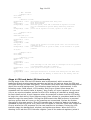
Stage 3: Interrupts and the HALT state
Interrupts and proper emulation of the HALT state, activated by execution of the HALT
opcode, to the CPU was now added. The GameBoy has five different interrupts that
can occur and these are: V-sync (LCD), LCD status, Timer, Serial transfer, and Joypad
input, where the LCD status interrupt can be made to happen for four different
reasons by changing settings for it in the external registers. The four reasons for this
interrupt will be further discussed in the next section. The GameBoy CPU can only
handle interrupts before each opcode fetch which means the CPU cannot deal with an
interrupt mid-instruction. For interrupts to occur they have to be enabled and for an
interrupt to be handled the interrupt master flag (called IME) has to be set. This flag
is controlled by the opcodes DI, EI, and RETI, and also by the interrupt handler. There
is however a bug in the hardware which made the HALT state quite complex to
implement. The HALT state is left when an enabled interrupt occurs, no matter if the
IME is enabled or not. However, if the IME is disabled the program counter register is
frozen for one incrementation process upon leaving the HALT state. This is devastating
if the instruction following the HALT instruction is another HALT instruction, as this will
cause the GameBoy's CPU to lock up because the program counter will forever warp
back to the second HALT instruction. The following example shows the behavior of the
HALT instruction:
Page 14 of 22
; IME = Disabled
; Example code 1:
0x76 (HALT)
0x00 (NOP)
; Execution of
ReadOpcode(1) = 0x76
HALT
--Interrupt-ReadOpcode(2) = 0x00
NOP
ReadOpcode(2) = 0x00
NOP
code:
; PC register is increased after every read
; Halt state entered
; Halt state exited
; Read new opcode, since IME is disabled PC register is frozen
; for one incrementation process making 0x00 being read twice
; Idle
; Since the PC register is frozen, opcode 2 is read again
; Example code 2:
0x76 (HALT)
0xEE 0x0A (XOR A,10)
; Execution of code:
ReadOpcode(1) = 0x76
HALT
--Interrupt-ReadOpcode(2) = 0xEE
XOR A,238
; Since the PC register is frozen opcode 2 will also be read as the
; immediate value
ReadOpcode(3) = 0x0A ; The immediate value of opcode 2 (0x0A) is now treated as an opcode
; instead
LD A,(BC)
; Example code 3:
0x76 (HALT)
0x76 (HALT)
; Execution of code:
ReadOpcode(1) = 0x76
HALT
--Interrupt-ReadOpcode(2) = 0x76
HALT
--Interrupt-; Same interrupt as last time since no interrupts can be are processed
; in between HALTs when IME is disabled
ReadOpcode(2) = 0x76 ; Same opcode is read again as PC is frozen
HALT
--Interrupt-ReadOpcode(2) = 0x76 ; And again because PC is re-frozen from exiting the last HALT state
...
...
; Continues until the GameBoy is turned off or the battery runs out
...
Stage 4: PPU and basic LCD functionality
During stage 4 the PPU and LCD basics was implemented, which means the
background and window drawing was done as well as the various steps the PPU and
LCD goes through to draw one frame. The window here works as a second background
above the normal background. The following steps had to be implemented, in the
following order: OAM search, LCD transfer, and H-sync (these three steps are
repeated until the entire frame is drawn), then finally a V-sync happens. H-sync and
V-sync are synchronization periods for the LCD's drawing to maintain a steady pace
for each draw period. H-sync happens when the scanline is drawn and the LCD waits
to begin the next while V-sync happens every time a frame is completed and the LCD
waits to begin the next frame. During the OAM search the OAM memory is scanned
and any sprites that will occur on the scanline are memorized. Sprites are further
discussed in the next section. The LCD transfer step is when the data to be drawn is
uploaded by the PPU to the LCD, which the LCD plots in real time. After this comes the
H-sync where the LCD prepares for the next scanline to be drawn. During the LCD
transfer stage the background, window, and sprites are drawn. When the LCD is
drawing it will ask the LCD Controller register (one of the external registers) what it
Page 15 of 22
should do. In this register background, window, and sprites can be enabled or
disabled by the cartridge program ROM, as well as a few other settings like which area
of the video RAM that should be used for tile maps and tile data. These tiles, that have
a predefined size of 8x8 pixels, are the only way to draw something on the GameBoy,
since the hardware is too limited to support anything else. Each pixel in a tile can have
one out of four different shades. This shade is extracted and checked against the
LCD's palette for what “color” the shade represents. Since the LCD is monochrome it
does not have colors but intensity levels of how lit the pixels are. The “colors” for all
pixels is stored in a two-dimensional array representing the screen. The same process
is repeated for the window. The GameBoy has a total of four intensities of pixel
lighting which are: off, slightly lit, almost lit and fully lit.
The LCD status interrupts were also added to the LCD during this stage. As
explained earlier this interrupt is customizable so that the cartridge program ROM can
select any combination of four triggers. The first trigger is the H-sync period, the
second the V-sync period (yes, V-sync can trigger two interrupts), the third is OAM
search, and finally there is the LCD Y coordinate interrupt. The last mentioned
interrupt is triggered when the LCD Y coordinate equals a certain value called the LCD
Y Compare. This value is changed from the cartridge program ROM through an
external register.
During the V-sync interrupt the two-dimensional screen array is also drawn to
the emulator program window using the GL_POINTS method, which draws one pixelsized dot on the coordinate specified by the function glVertex2i(x,y). To enhance the
GameBoy feel the “color” 0 has been converted to the color of the GameBoy LCD
when it is turned off. All “colors” are then defined as more intense shades of that color
until black is reached.
Stage 5: Sprites and DMA transfers
Implementing sprites took some thought due to the limitations of the GameBoy LCD,
where only 10 sprites can be handled per scanline. These 10 sprites are extracted in
the most primitive way: it is the first 10 sprites that appear in memory for that
scanline to be drawn. To simplify the drawing in the emulator these sprites are sorted
by a variant of the Shell Sort algorithm. This variant of Shell Sort will perform at the
same worst case as Bubble Sort (O(n2)) but has a better best case of about O(n4/3).
The sprites are sorted according to the drawing rules, which are: sprites with an X
coordinate closer to 0 has priority over the ones with an X coordinate further away
from 0, so in the event of sprites overlapping each other the sprite closer to 0 will
appear above the other one. If the sprites would have the same X coordinates the
sprite that appears first in OAM gets priority over the other sprite. Sorting the sprites
according to those rules makes the drawing several times easier as the sprites can be
drawn in the order they appear.
The real hardware does not draw like this though. Since the LCD in hardware
has a fixed beam-direction it will draw the sprites in the order they would appear on
screen, starting from the left. This actually means that in hardware everything is
calculated for each pixel (background, window, and sprites). If the drawing is not
pixel-based there may be some graphical anomalies from wrongly timed interrupts in
the case where the LCD Y coordinate interrupt is used for animation.
The OAM provides instructions for how the sprites are to be drawn. These
include flipping the sprite along the vertical axis or the horizontal axis, or both, and
which of the two sprite palettes that should be used to choose the pixels' colors. There
is also a setting in the LCD controller that when set enables sprites to have double
height. When this setting is set the sprite pairs are stored next to each other in the
OAM memory. The upper sprite is always located on an even address and the lower
Page 16 of 22
sprite is always located on an odd address. The upper sprite also always appear before
the lower sprite in memory. Selecting the upper or lower sprite - which sprite to draw
depends on which scanline that is being drawn - is then performed like this:
Upper sprite: [memory address defined by OAM] & 0xFE
Lower sprite: [memory address defined by OAM] | 0x01
What the above pseudo code does is to reset the last bit in the address given by the
OAM making the address even if the upper sprite is wanted, and sets the last bit of
the address if the lower sprite is wanted. The OAM can also decide if a sprite should
be drawn above or behind the background. This also includes the window. When this
option is set, sprites will only be drawn where the current color is 0, as that color is
transparent both for the background and window. The same thing applies to sprites,
the color 0 is transparent, so the background and window will shine through.
DMA transfers were more straightforward. The DMA transfer will copy 160 bytes
from video RAM to the OAM. Where to start copying is specified by writing to the DMA
transfer register. Doing so also initializes the transfer. Since this register is only one
byte the entire address cannot be contained so only the upper half of the address is
used, and the lower half is always 0. So if 0xA5 is written to the DMA transfer register
it means address 0xA500 will be the start address of the transfer.
Stage 6: The joypad
This is probably the simplest part to implement of the entire emulator. Since the
joypad can receive input at any time, a function that polls the windowing system for
events and then processes all the keyboard events was made. Since the D-pad is
placed on a pivot inside the GameBoy certain rules had to be applied in the polling
function: up & down and left & right are D-pad combinations that cannot be pressed
at the same time on a healthy GameBoy, and therefore these combinations should not
be allowed on a properly coded emulator.
After each poll the external registers are updated with what buttons where
pressed, and if the joypad interrupt is set the interrupt flag will also be triggered by
the Joypad activity.
The joypad can also be turned on and off which means that when the joypad is
turned off, all button activity must be ignored and the external register reset on every
poll. An interesting note about the external joypad register is that instead of the
corresponding bits being set to 1 when something happens, this is their normal state.
Bits are reset when something happens. This also applies when turning the joypad on
or off as a 1 turns it off and a 0 turns it on.
Page 17 of 22
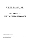
Results
In its current state the emulator can unfortunately not run any official cartridge
program ROMs. This is due to what I think is one final bug in the timing. The
performance is almost up to full speed when it is being run on my stationary
computer. Running it on my laptop gives a quite big hit on performance, since my
laptop has only a single core 1.4 GHz Intel CPU. The biggest bottle neck is the
keyboard polling which is to be expected as the windowing system is polled once
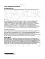
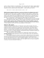
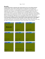
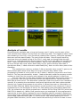
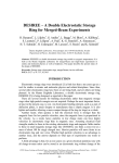
every 4 CPU cycles (or once per machine cycle if you wish). Below are some images
showing the current state of the emulator. The first picture shows the emulator as the
BIOS is setting up the hardware to run a cartridge program ROM. The next eleven
pictures show Blargg's CPU instruction tests and the results they produce after
execution in the emulator. They all show “Passed” which means every CPU instruction
in my emulator works exactly as on the DMG. The last three pictures show Blargg's
instruction timing test and the game Alleyway during its start screen and an AI
controlled demo level. I would have liked to show some screen shots from Tetris, but
the game is refusing to draw anything in the current state of the emulator.
Page 18 of 22
Analysis of results
Developing this emulator was a long and bumpy road. I had to rewrite parts of the
code several times before it would reach a functioning state. The biggest hurdles I had
were drawing on the LCD, a non-functional reading from memory, and a few opcodes
that were not the least friendly. The part of the emulator I found myself rewriting
most was the cycle-based timing of the CPU. I really had not thought that through
properly, so I had started with decrementing the CPU clock right after the opcode was
done. I later turned this into a look-up table. I had not yet realized that I needed to
do more things each cycle. When that finally hit me, which was way later than it
should have been, I made a function called AddCycle() that runs the other parts of the
GameBoy.
The reading-from-memory problem I did not actually solve myself. I gave up on
that problem after about three days of trying to find the bug. When a few
programming friends of mine could not see it either I asked my supervisor who finally
found it. The bug was shamefully simple: I had accidentally used the program counter
register as index into the memory map instead of the actual address to read from.
The war with the opcodes was probably the biggest battle during this project. In
the beginning I had only one document which was compiled from various text files
that used to exist online. This document contained a few errors and it even missed an
opcode! It is amazing how emulators could work back then with that undocumented
opcode, but I guess most games do not utilize it. When there was no information on
how the DAA (Decimal Adjust Accumulator) opcode worked in the document I used, I
contacted byuu, the developer of bsnes, for help getting good information about this
CPU. He showed me an official programmer's manual for the Zilog Z80 CPU (which the
DMG CPU is based on). While a few opcodes were not explained in this programmer's
manual due to them being replaced by more GameBoy-specific opcodes it helped me
solve many bugs, implement my first version of the DAA opcode, and find the missing
opcode and implement that (SBC n). At this point I was almost passing the CPU's
program ROM execution, but for some reason the last thing it tried to do was to write
Page 19 of 22
to an external register that is not mentioned anywhere in the documents I had access
to at this point of the project. And as it turns out, it is not mentioned in any
documentation I have today either. This was my first contact with external register
0xFF50, where the least significant bit presumably tells the CPU whether to read from
the program ROM or the cartridge ROM for the 0x0-0xFF address range. Since I to this
point had used a boolean in the CPU code to check for when to read from the CPU's
program ROM I could now remove it and use this external register instead which
resulted in nicer code.
Thinking I had fixed the opcodes and the CPU's program ROM execution I used
Blargg's GameBoy emulator test suite, a set of ROMs developed by Shay Green using
a real GameBoy as testing-platform. Shay Green is known as Blargg to the emulator
community. The emulator failed all 11 tests, which meant I had at least one faulty
opcode in each opcode group. As all opcodes did exactly what the documents I had
specified, I was a bit depressed. I actually tracked down an e-book scanned from the
official programming guide of the GameBoy and GameBoy Color in order to get
forward. I found this e-book thanks to a tip from a user on byuu's bsnes forum.
Looking over all the opcodes again I found some really disturbing differences between
this manual and those I already had. Now I could finally implement everything
correctly, I thought. I changed the opcodes to match the official programmers guide
and ran Blargg's tests again. Now a lot of the tests passed, but some still failed. But at
least now I could count the failures on my fingers. There were three tests that refused
to pass: “DAA”, “LDHL SP,e”, and “ADD SP,e”. Regarding the stack pointer-related
opcodes I do not know the reason behind one of the required steps needed for them
to execute correctly. That is, during the addition between the stack pointer and the
signed variable e, e is unsigned during the evaluation of the flags. What concerned me
most was the “LDHL SP,e” opcode though, for this opcode even the official
programmer's guide is wrong in how it works. While the manual tells me the carry and
half-carry flags are set if the resulting value overflows in the 3rd or 4th nibble (the
nibbles of the most significant byte) the flags are really set by overflows from the
nibbles in the least significant byte. The “DAA” opcode I assumed from the beginning
would be a nightmare to implement and I was right. Though my second solution
worked, it was very slow and I started to run short of time. At this point I noted that
Gambatte used an approach similar to what I used, so I copied its optimized version
of the algorithm leaving my own slow version as a comment.
Besides all these hiccups the development have been pretty straightforward and
only a few timing issues remain in the parts that I was to implement. No information
on how to do that timing exists and I have not figured out how to do it. Every fix
attempted left the results unchanged or made things worse. Also the opcode cycle test
fails with “Failure #255” which according to the source code of that test, does not
exist.
Future work
The only major thing left to understand about the GameBoy in order to make
emulation more accurate is the LCD read pointer. When the LCD reads from OAM or
video RAM and that same memory is read by the CPU, the CPU will receive the data
pointed to by the LCD read pointer instead of the data at the requested address. This
can probably be achieved in two ways: the first one is to write a test program that is
to be uploaded to the real GameBoy. This test program would then run a very
extensive test and print the results on the screen. These results would then be
gathered in such a way that they can be used to implement this function. The other
method is to dump the program ROMs of both the PPU and LCD (if it has its own
program ROM that is). This would require them to be removed from the GameBoy and
Page 20 of 22
have them “decapped”, and from there extract the program ROMs and dump the
opcode table. Using that information it should be possible to decompile the program
ROMs into assembler. From the resulting code from that process it might be seen how
the LCD read pointer operates. Dumping the program ROM of the PPU and the LCD
(again, if it has a program ROM) may also help in optimizing, and maybe even
correcting parts we do not know are wrong in the PPU emulation.
Page 21 of 22
Summary and conclusions
To complete this project on time a few things that does not affect playability too much
would have to be sacrificed: sound, serial connection and extension chips. The
extension chips do have an impact on the number of playable games though. Since
the GameBoy has a 4 MHz CPU and a 60 FPS screen the code has to be quite fast for
the emulator to run at full speed.
Due to me dropping a few things there were only four components to
implement: CPU, PPU/LCD, Memory and Joypad. These components where
implemented using the language C++ with help from OpenGL and the OpenGL Frame
Work (GLFW). The implementation was a bit bumpy but most things where solved in
the end. Currently there is probably only one timing issue left to straighten out. I had
to implement this emulator in stages to keep the project under a manageable
complexity. The process was split up into these stages: "The main system", "CPU
instructions and memory handling", "Interrupts and the HALT state", "PPU and basic
LCD functionality", "Sprites and DMA transfers", and "Joypad".
The biggest problem found during the implementation process was that I
discovered I had not grasped how complex some of the timing is in the GameBoy.
That mistake cost me a couple of rewrites of the CPU code. On a deeper level I had
problems with especially one CPU instruction that was seemingly wrongly described in
all documentation I had access to. This included the official development manual by
Nintendo. Besides that problem I had not had any major issues with the
documentation, just some small hiccups with typing mistakes in the code and a few
moments where I understood the documentation wrong.
In conclusion, using the documents that exist online it is possible to write a
GameBoy emulator with quite good compatibility and accuracy. The documents are
however somewhat tricky to understand and contain a fair amount of errors, so some
experience in reading technical documents and reading between the lines is required
to fully understand them. The documentation needed to write an emulator as accurate
as Gambatte is however not publicly available in any other format than the Gambatte
source code, and the Gambatte source code is not a light reading. There is currently
only one major question mark in GameBoy emulation and that is how memory
accessing is done when the video RAM and OAM are busy. This behavior has not been
figured out and an extraction of the PPU program ROM is probably necessary to solve
that riddle. Extracting the PPU program ROM was not done in this project because it is
a very expensive and slow process, and it requires an understanding of how the guts
of a microchip works.
Page 22 of 22
References
All links where confirmed alive on 2011-05-29.
[GBAut] Gadget Autopsy: The Nintendo Game Boy | PCWorld
http://www.pcworld.com/article/162588/gadget_autopsy_the_nintendo_game_boy.html
[NinWiki] Game Boy - The Nintendo Wiki - Wii, Nintendo DS, and all things Nintendo
http://nintendo.wikia.com/wiki/Game_Boy
[GBHard] GameBoy Hardware (only used for images)
http://fms.komkon.org/GameBoy/Tech/Hardware.html
[CPUProROM] CPU Program ROM (no website title)
http://www.neviksti.com/DMG/
[Specs] Specifications (a.k.a. Pandocs)
http://nocash.emubase.de/pandocs.htm
[IntGBLCD] Intercepting the Gameboy LCD « Flashing LEDs
http://flashingleds.wordpress.com/2010/10/26/intercepting-the-gameboy-lcd/
[DuoDream] DuoDreamer's Dreamscape (GameBoy memory map explained)
http://gameboy.mongenel.com/dmg/asmmemmap.html
[Dwedit] Super Mario Land 2 - glitched route (Post by Dwedit)
http://forum.speeddemosarchive.com/post/super_mario_land_2__glitched_route_6.html
[GBASnd4] Gameboy Advance Sound Channel 4 (Works the same on GameBoy)
http://belogic.com/gba/channel4.shtml
[Z80] Z80 Family CPU User Manual
http://www.zilog.com/docs/z80/um0080.pdf
[GBProgMan] GameBoy Programming Manual Version 1.0
http://www.romhacking.net/docs/%5B544%5DGameBoyProgrammingManual.pdf
[GBDEVFAQs] GB DEV FAQs
http://www.devrs.com/gb/files/faqs.html
[EmuTGBp4] EmuTalk Forums: Game Boy - Post 4
http://emutalk.net/showpost.php?p=200173&postcount=4
[bsnes] byuu's homepage
http://byuu.org/bsnes/
[Gambatte] Gambatte project at SourceForge
http://sourceforge.net/projects/gambatte/
[Dolphin] Dolphin, a Gamecube / Wii / Triforce Emulator - Google Project Hosting
http://code.google.com/p/dolphin-emu/