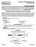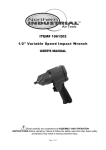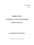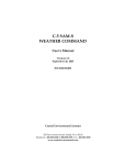
1
EMC-6 EMC-6L EMC-6 EMC-6L Hybrid Fan Controller User Manual www.hctcontrols.com 021-00360 Rev A.2 1 Copyright © High Country Tek, Inc. – 2014 EMC-6 EMC-6L Revision Record Rev Rev A Rev A.1 Description Date Released Last Updated by Initial Revision 9-May-14 WB E-fan and hydrualic fan auto reverse curves updated 2-Jun-14 WB Rev A.2 controller weight is added, format updated Updated product photo on cover page 021-00360 Rev A.2 2 27-Jun-14 WB 4-Oct-14 BC Copyright © High Country Tek, Inc. – 2014 EMC-6 EMC-6L Contents Revision Record ...................................................................................................................................................... 2 HCT Introduction ..................................................................................................................................................... 4 Product Use Limitations .......................................................................................................................................... 4 Product Application Guidelines ............................................................................................................................... 5 Controller Specification ........................................................................................................................................... 6 Controller Dimensions / Mounting Information ........................................................................................................ 7 Wiring Diagram ....................................................................................................................................................... 8 PINOUT ................................................................................................................................................................... 9 LEDs / Diagnostic Codes ...................................................................................................................................... 10 Accessories ........................................................................................................................................................... 11 Example Applications ............................................................................................................................................ 12 GUI Installation ..................................................................................................................................................... 13 GUI Overview ........................................................................................................................................................ 14 File ................................................................................................................................................................ 15 Controller ...................................................................................................................................................... 15 Password ...................................................................................................................................................... 16 Help ............................................................................................................................................................... 17 Exit ................................................................................................................................................................ 17 Dashboard .................................................................................................................................................... 18 Control Messages ......................................................................................................................................... 20 Stimulus Settings .......................................................................................................................................... 22 Analog Inputs ................................................................................................................................................ 24 Bank Control ................................................................................................................................................. 25 Bank Interlocks ............................................................................................................................................. 29 Interlock Selection......................................................................................................................................... 29 Manual Control .............................................................................................................................................. 31 Global Settings .............................................................................................................................................. 33 View Graphs ................................................................................................................................................. 36 Appendix A Fan Status Messages ........................................................................................................................ 37 Appendix B Troubleshooting Communication Port Adapters ............................................................................... 39 021-00360 Rev A.2 3 Copyright © High Country Tek, Inc. – 2014 EMC-6 EMC-6L HCT Introduction Welcome to High Country Tek Inc. HCT is North America’s foremost independent designer and producer of modular, ruggedized digital and analog electronic controllers for the fluid power industry. From our factory in California, we manufacture ‘specialty’ controllers for specific functions and the user programmable ‘DVC family’ to enable large area networked system solutions. The modules are used in mobile, industrial and marine applications. They are also applied successfully in other industry segments. HCT products are encapsulated in solid flame resistant material for maximum durability, electrical integrity and complete environmental security. HCT is a market leader in many application arenas, including hydraulic generator, e-Fan and hydraulic fan system controls. These controllers facilitate significant fuel, emission and operational savings. HCT’s market neutrality offers integration with any hydraulic OEM valves, pumps, sub-systems or systems. For more information, please visit us at: www.hctcontrols.com. Product Use Limitations HCT products may not be suited for any of the following applications: Any product which comes under the Federal Highway Safety Act, namely steering or braking systems for passenger-carrying vehicles or on-highway trucks. Aircraft or space vehicles. Ordinance or military equipment. Life support equipment. Any end product which, when sold, comes under U.S. Nuclear Regulatory Commission rules and regulations. HCT does not have any performance assurance programs for testing their products for the above applications. HCT's products are not designed for these applications and HCT does not warrant, recommend, or specifically approve its products for these applications. The user shall be solely responsible for any loss or damages occasioned by breach of the provisions of this paragraph and shall carry product liability and liability insurance to insure against such loss or damages. 021-00360 Rev A.2 4 Copyright © High Country Tek, Inc. – 2014 EMC-6 EMC-6L Cautions Changing setup values or operating modes while a machine is running may cause unintended machine movement. It could lead to possible injury or death. Any moving parts should be disabled prior to changing setup values or operating modes. In every case, exercise caution and work should be completed only by qualified personnel. Product Application Guidelines ALWAYS do the following FULLY read this manual and accompanying data sheets BEFORE starting. Isolate this unit from all other equipment BEFORE any form of welding. Isolate the controller from ANY form of battery charging or battery boosting. Be aware of the electrical & mechanical connections, and the expected reactions of the equipment. Operate the units within the temperature range. Use the correct tools to do the job (i.e. P.C., software) etc. Separate High Voltage AC cables from Low Voltage DC signal and supply cables. Make sure power supply is CORRECT, ELECTRICALLY CLEAN, STABLE, and rated for the full load. Make sure the controller output voltage & current is compatible with the equipment. All unused wires / terminals should be terminated safely. Ensure ALL connectors have no unintended SHORT or OPEN circuits. Ensure ALL connectors are wired correctly, secure, locked in place and fully connected. Disconnect or connect wires to or from this unit only when the power supply is disconnected. Use adequate screening in areas of intense Radio Frequency fields. Ensure ALL work areas are clear of personnel before operating the controller. Follow and abide by local and country health & safety standards. 021-00360 Rev A.2 5 Copyright © High Country Tek, Inc. – 2014 EMC-6 EMC-6L Controller Specification Housing Type HCT encapsulated block, flameproof Power Supply Voltage 9 to 32VDC (Absolute Maximum) Current Consumption Load current + 200mA Quiescent (Max) Command Inputs Programmable SAE J1939 CAN messages 3x option selection switches (ON/Off) 12x inputs for fan diagnostics (ON/Off) 6x inputs for sensors or Potentiometers (Max temp = 50, min temp = 2M) Outputs Up to 3x 0-5Vdc @ 10mA analog outputs Up to 6x 0-100% PWM (Sourcing for EMC-6, Sinking for EMC-6L, max 500mA, short circuit protection) 1x 3A Proportional PWM current output 1x 3A on/off output for reverse coil 1x 0.5A on/off output for alarm indicator 1x 5V±5% regulated reference voltage PWM Freq. Software adjustable - 33 to 500Hz Module Connector 48-way Cinch 1.5mm SHS Header, Cinch PN: 581 01 48 011 Communication Mini USB or 4-way Weatherpak for RS232 Housing Material Black, Polycarbonate Encapsulation Flameproof epoxy resin Mounting 2x ¼” x20 SAE Grade 2 screws Temperature Range -40 to +85ºC (Operational) -60 to +90ºC (Storage) NEMA/IP Rating NEMA 6P/IP68 CAN Data Rate 250Kbps, 500Kbps and 1000Kbps 021-00360 Rev A.2 6 Copyright © High Country Tek, Inc. – 2014 EMC-6 EMC-6L Controller Dimensions / Mounting Information Controller weight is approximately 1.26Lbs. Mount controller in an easily accessible location. Mount controller to a flat surface. If mounting to a hydraulic product, allow at least a 2mm air gap underneath the unit. Use BOTH mounting holes with correct hardware. DO NOT mount controller with connector facing UP if possible. Recommended, ¼-20 SAE Grade 2 screws, Dry Torque – 4 Ft-lbs, Lubricated – 3 Ft-lbs. Figure 1 021-00360 Rev A.2 7 Copyright © High Country Tek, Inc. – 2014 EMC-6 EMC-6L Wiring Diagram 9 – 32VDC Power Input FUSE C2 - Ana_In 1 K1 - Power_In D2 - Ana_In 2 a1 - Power_In E2 - Ana_In 3 a2 – Not used momentary F2 - Reverse_In C1 - Ana_In 4 G2 - Fire_In D1 - Ana_In 5 H2 - Ignition_In E1 - Ana_In 6 C3 - GND D3 - GND E3 - GND RS232 A1 - RXD F3 - GND A2 - TXD A3 - Not used B1 - CAN_Hi J1939 I/O B2 - CAN_Lo B3 - GND F1 - Diag_In 1 G1 - Diag_In 2 d2 - Alarm_Out d3 - Reverse_Out latched latched 0.5A On/Off (sourcing) 3A On/Off (sourcing) f1 - GND a3 - Ref_Out 5V±5% @ 200mA 0-5V @ 5mA (Pin G3) Bank 1 0.5A PWM % (Pin b1) EMC-6 EMC-6L Bank 2 0.5A PWM % (Pin b2) 0-5V @ 5mA Output (Pin H3) H1 - Diag_In 3 J1 - Diag_In 4 J2 - Diag_In 5 Bank 3 J3 - Diag_In 6 K2 - Diag_In 7 Bank 4 0.5A PWM % (Pin c1) 0-5V @ 5mA Output (Pin d1) 0.5A PWM % (Pin c2) 3A Prop. PWM (sourcing, Pin e1) K3 - Diag_In 8 e2 - Diag_In 9 Bank 5 0.5A PWM % (Pin b3) e3 - Diag_In 10 Bank 6 0.5A PWM % (Pin c3) f2 - Diag_In 11 f3 - Diag_In 12 Mini USB Port Figure 2 PWM% outputs are sourcing for EMC-6. PWM% outputs are sinking for EMC-6L. 021-00360 Rev A.2 8 Copyright © High Country Tek, Inc. – 2014 EMC-6 EMC-6L PINOUT The module has a 30-Pin Cinch connector and an 18-Pin Cinch connector. Either the RS232 port from the 30-pin Cinch connector or the mini USB port at the top of the controller can be used for serial communication. 021-00360 Rev A.2 9 Copyright © High Country Tek, Inc. – 2014 EMC-6 EMC-6L LEDs / Diagnostic Codes The module has 4 LEDs. GUI LED blinks GREEN ------------------------------------------------------ Normal communication GUI LED steady GREEN ------------------------------------------------------ No communication CAN LED steady RED and Error Status blinks GREEN --------------- CAN message timeout CAN LED blinks RED -------------------------------------------------------- Intermittent CAN message timeout CAN LED blinks green fast ---------------------------------------------------- Normal operation Error Status LED steady GREEN ------------------------------------------- Normal operation Error Status LED blinks RED 1~6 times ----------------------------------- Bank #1-6 diagnostic error. Error Status LED blinks GREEN 1 time ------------------------------------ CAN message timeout Error Status LED blinks GREEN 2 times ---------------------------------- Analog value out of range Error Status LED blinks GREEN 3 times ---------------------------------- CAN value out of range Error Status LED blinks GREEN 4 times ---------------------------------- Reference Voltage low When multiple errors occur, the LED sequences through the error codes. Module status LED steady GREEN ----------------------------------------- Normal operation Module status LED blinks RED/GREEN ----------------------------------- Reverse cycle Module status LED steady RED --------------------------------------------- Fire Module status LED blinks GREEN ------------------------------------------ Low voltage Alarm indicator blinks RED 1~6 times at 0.5 seconds intervals ----- Bank #1-6 diagnostic error Alarm indicator sequences through the error codes -------------------- Diagnostic errors on more banks Alarm indicator steady red ----------------------------------------------------- J1939 times out Alarm indicator blinks red 1 time at 1.0 seconds intervals ------------- Any fan bank in reverse 021-00360 Rev A.2 10 Copyright © High Country Tek, Inc. – 2014 EMC-6 EMC-6L Accessories 999-10104 999-10107 999-10077 30-pin Harness (3M length) 18-pin Harness (3M length) 48-pin Mating Connector Kit CD-EMC-6 108-00134 999-10075 108-00119 PC set-up software System diagnostics Data logging feature USB Mini B (2M length) 4-way weatherpak to RS232 RS232 to PC USB 206-00083 (3/8”-18NPT) 206-00083M (M12x1.5) Liquid thermistor -40°C to +150°C. 021-00360 Rev A.2 999-10213 (Mating connector) 206-00084 (3/8”-18NPT) For both liquid and dry thermistors Dry Thermistor -40°C to +150°C. 11 Copyright © High Country Tek, Inc. – 2014 EMC-6 EMC-6L Example Applications Figure 3 021-00360 Rev A.2 12 Copyright © High Country Tek, Inc. – 2014 EMC-6 EMC-6L GUI Installation Use the default file locations for easy future update when installing the Graphical User Interface (GUI). The user has the option to choose file location. Do NOT run the GUI from a network drive as it needs to access certain files only in the local Windows directories. System Requirements Windows XP, Vista, Windows 7 or 8, 100MB or greater free disk space. Installation Steps Insert the CD and follow the on screen instructions. This will install the GUI, manual and help files. Go to Help menu, install the CommFront driver or Mini USB driver. To insure a complete install for CommFront, install it twice. Install all software and drivers before plugging in the USB dongle or USB cable. Launch the GUI Click Start HCT Products Fan Drives EMC-6 021-00360 Rev A.2 13 Copyright © High Country Tek, Inc. – 2014 EMC-6 EMC-6L GUI Overview At start up the GUI searches all the PC communication ports and identifies the controller. The GUI appears once the module is identified. Device ID – Determines the module’s PGN addresses on the SAE J1939 bus. The user may command multiple EMC-6 modules on a single SAE J1939 bus. The default Device ID is 1. Log Data – logs the operational data in Excel format. See page 19 for details. Work Off Line – allows the user to work with GUI offline without the module. The user can load any existing data files, modify them or create new data files and save them to the PC without an OEM password. Find Module – the GUI tries to find the controller and reconnect it. The EMC-6 can also be powered by a +5V USB to allow configuration without a 12/24VDC system. The user may communicate, change, and save settings to the unit without connecting to the E-Fans. 021-00360 Rev A.2 14 Copyright © High Country Tek, Inc. – 2014 EMC-6 EMC-6L File Save settings to a file (.txt) – saves the settings to a data file that may be loaded into any EMC-6 controller. Read settings from a file (.txt) – loads the data file from the PC to the EMC-6 GUI. At this point the data is not written to the controller yet. Read data file and Save to unit – loads the data file from the PC, writes to the controller and permanently saves the settings. Read Thermistor data from a file (.dat) – loads the thermistor data file from the PC to the GUI to match the thermistor in the system. The data are not written to the controller yet. Settings not permanently saved will be lost after a power cycle. Controller Write all settings to controller – executes all “send new settings” on every Tab and saves settings to Volatile Memory (RAM). It does not save settings permanently, a Power Cycle will restore permanently saved settings. Reset to last saved settings - like a Power Cycle, the module reloads the settings permanently saved in Non-Volatile Memory. Reconnect to Controller – the GUI resets communication with the module, re-reads and updates all variables. Permanently Save settings – saves the settings to its Non-Volatile Memory (permanent memory). Open Error Logging Window – opens the internal data logging windows that display the error situations, such as the count of timeouts, coil open/shorts, fire input ON, the high and low error when bank stimulus and diagnostics occur. 021-00360 Rev A.2 15 Copyright © High Country Tek, Inc. – 2014 EMC-6 EMC-6L Password OEM Password – allows full access to view settings, setup data files, apply changes or upload data files to controllers and manual control. Passwords are ‘cAsE SeNsitivE’ 021-00360 Rev A.2 16 Copyright © High Country Tek, Inc. – 2014 EMC-6 EMC-6L Help About Controller - displays the controller type, BIOS, Serial No, Activation Date, the GUI revision and Part Number, contact information, etc. Help Files – opens the folder C:\\HCT products/Fan Drives/EMC-6 where the manual and other related information are located. USB drivers – opens the folder where USB driver installation instruction is located. Exit Exit Program – exits the GUI and frees up the communication port and memory used by the application. 021-00360 Rev A.2 17 Copyright © High Country Tek, Inc. – 2014 EMC-6 EMC-6L Dashboard The Dashboard monitors the fan system in real time. Configure all tabs from left to right so that the subsequent tabs have the correct background settings. There are six operational states for the fan bank gauges: Normal – All the fans in this bank are operating normally. Diag. Error – At least one fan in this bank is reporting an error. Manual – All the fans in this bank are in manual mode. Reset – At least one Locked Rotor error was detected. The module is resetting all the fans in this bank. Dwell – The fans in this bank are freewheeling before entering into reverse direction. Reverse – The fans in this bank are in Reverse. Engine RPM - displays the engine RPM from SPN 190, or the error value in “Stimulus Settings” when the engine RPM message times out. 021-00360 Rev A.2 18 Copyright © High Country Tek, Inc. – 2014 EMC-6 EMC-6L Log Data - logs the operational data in Excel format. The file size is only limited by the PC’s hard-drive capacity. Each log begins with a list of settings followed by operational information. The sample rate depends on the workload of the PC and the controller at the recording. A timestamp scales the logs appropriately. Subsequent logs may be saved in a new file or appended to the original file by selecting the original file. The log file is saved as a .csv file. Microsoft Excel can be used to open this file. Gauges PWM/RPM – displays either the real time PWM % or the Calculated Fan RPM. Fan Operating Status and Fan Error Status – indicates the fan status. Green – indicates that fans are running. Gray – indicates that fans are OFF. Red – indicates one or more fans have errors. It happens when the respective diagnostic pin does not have voltage when the fan is running; or has voltage when the fan is not running. Fan ID numbers are assigned in the “Bank Interlocks” tab. State Indicators – displays the state of the inputs, RPM, J1939 messages, Supply voltage and Reference voltage. Green – the input is on or active. Yellow – the input is in an intermediate state (i.e. RPM low). Red – the input is off or timed out, or in an error state like Fire ON. Stimulus Bar Graphs – displays the read time readings of the stimulus. Select the stimulus from the pull down menu. Scale the bar graphs. The units are set in the “Stimulus Settings” for CAN values and in the “Analog Settings” for the Analog Inputs. 021-00360 Rev A.2 19 Copyright © High Country Tek, Inc. – 2014 EMC-6 EMC-6L Control Messages The user may define up to 10 CAN messages as the controlling inputs. Currently the EMC-6 supports the SAE J1939 protocol. The first message is always EEC1, Engine RPM (hard coded). 021-00360 Rev A.2 20 Copyright © High Country Tek, Inc. – 2014 EMC-6 EMC-6L To configure Control Messages from a default file included in the GUI installation: Select Msg From a File – opens the control message file and displays the Message Window. Select PGN or Select Message Name, the GUI will match PGN and Message Name. Accept or Cancel the message. Check to enable the message. Select SAE J1939 as the CAN Msg. Format. Mask SA – if checked, the source address is ignored. The module can receive messages from any source address for the specified PGN number. . To configure Control Messages manually: Enter the PGN number, Source Address, Message Name and the message time out in milliseconds. Check to enable the message. Select SAE J1939 as the CAN Msg. Format. Mask SA – if checked, the source address is ignored. The module can receive messages from any source address for the specified PGN number. Send New Settings – loads the new settings into the unit’s RAM memory and activates these messages. Permanently save settings Control messages are now available on the Stimulus Settings Tab. Msg. State Green – the message is Active. Red – the message is Timed Out. Grey – the message is Inactive. Hex-Decimal – switches PGN numbers between Hexadecimal or Decimal format. 021-00360 Rev A.2 21 Copyright © High Country Tek, Inc. – 2014 EMC-6 EMC-6L Stimulus Settings The user may define up to 10 CAN messages as the inputs. The first message is always EEC1, Engine RPM. Only the error value can be changed for this SPN. To configure Stimulus from a default file included in the GUI installation: Select specific Control Message from the pull-down menu defined in “Control Messages” Tab. Select SPN Selection text file. A new window will open. Select the stimulus from the pull-down menu Stimulus (SPN), the respective values appear automatically. 021-00360 Rev A.2 22 Copyright © High Country Tek, Inc. – 2014 EMC-6 EMC-6L The stimulus has to match the control message. E.g., SPN177 Transmission Oil Temperature matches J1939 TF. If the Stimulus does not match the Control Message, this window will appear: Match the Stimulus to the Control Message. Accept or Cancel the selection. Enter the Error Value on Stimulus Settings tab. This will be the stimulus value when this message times out. The user can also modify the values on Stimulus Settings tab. To configure Stimulus Settings manually: Select Stimulus from the list defined in “Control Messages” Tab. Enter a name in the Stimulus Name (SPN). Use the SPN number and/or a short description. Enter values for the following: Start Bit – The bit number where the data begins. Bit numbering starts at 0. Read Bits – The number of bits in the data package. Offset – The offset is applied after the Gain Calculation. Gain – The Scale Factor for the Gain Calculation. Error Value – the value used for the stimulus when the message times out. Units – the unit of the stimulus value. Send New Settings – loads the new settings into the unit’s RAM memory and activates these stimuli. Permanently save settings. Stimulus Settings are now available on the Bank Control Tab. 021-00360 Rev A.2 23 Copyright © High Country Tek, Inc. – 2014 EMC-6 EMC-6L Analog Inputs The user may define up to 6 analog inputs, either thermistor or potentiometer inputs. To configure Analog Settings: Pull-Up (+5V) – Select On for thermistors. When on, the module sources current for use with resistive thermal devices. Select Off for potentiometer or analog inputs. Enable – check to enable the input. Input Type – Select Thermistor or Voltage type. Analog Name – name the input. Low Value & High Value – the minimum and maximum values the sensor can report. Send New Settings – loads the new settings into the unit’s RAM memory and activates these stimuli. Permanently save settings Analog Settings are now available on the Bank Control Tab. 021-00360 Rev A.2 24 Copyright © High Country Tek, Inc. – 2014 EMC-6 EMC-6L Bank Control The user may define independently up to 6 banks of electric fans and up to 1 bank of hydraulic fan. For each bank, the user may define up to four stimulus inputs. Fan Bank n – selects the fan bank to be configured. Name the Fan Bank n – names the bank to identify it on the GUI. Stimulus – selects stimuli for this bank. All previously configured stimuli are in the pull down menu. Multiple fan banks may use the same stimuli. Maximum Set-Point – the stimulus value that makes the fan bank run at full speed. Minimum Set-Point – the stimulus value that makes the fan bank run at minimum speed. Alarm High – the stimulus value that trips the High Alarm condition. Alarm Low – the stimulus value that trips the Low Alarm condition. Demand % – displays the normalized percentage of demand. Message State – displays green when normal, red when timed out. 021-00360 Rev A.2 25 Copyright © High Country Tek, Inc. – 2014 EMC-6 EMC-6L The Dashboard will display Analog Data Error or CAN Data Error when the value meets or exceeds the Alarm High or Alarm Low setting. Fan Bank Profile – defines specification of all E-fans in the specific bank: Maximum RPM – the rated fan Maximum RPM. Minimum RPM – the rated fan Minimum RPM. Zero Fan Speed PWM – the PWM % that causes the fan(s) to stop (figure 4). Maximum PWM – the PWM % that causes the fan(s) to run at maximum RPM (figure 4). Minimum PWM – the PWM % that causes the fan(s) to run at minimum RPM (figure 4). Reverse PWM – the PWM % that causes the fan(s) to run in Reverse (figure 4). Auto Reverse Enable/Disable – enables or disables the Auto Reverse feature. Auto Reverse Interval (minutes) – see the EMC-6 reverse cycle definition (figure 5). It is the time between the st nd 1 reverse signal and the 2 auto reverse signal. Reverse Period (seconds) – see the EMC-6 reverse cycle definition (figure 5). It is the total time of ramp up in reverse direction, full fan reverse time and ramp down time in reverse direction. Ramp up and down time equal to the dwell time set on the “Global Settings”. Minimum Run Time Seconds – the minimum run time. It prevents the fans from repeatedly starting and stopping when there is low demand and helps reduce thermal cycling in the equipment. Minimum Demand % – determines the fan minimum speed until the controlling input demands a higher speed. This eliminates the fans start up delay and quickly responds to fast changing heat loads such as Charge Air Coolers etc. Send New Settings – loads the new settings into the unit’s RAM memory and activates these stimuli. Permanently save settings Stimulus Grouping – in each fan bank, the inputs can be grouped. The following rules apply: Stimulus grouping for one bank does not affect how the same inputs control other banks. Analog inputs out of range act the same as J1939 message timeout. Error values take effect for them. 100% demand is the error value for thermistor input high, 0% is for thermistor input low. 021-00360 Rev A.2 26 Copyright © High Country Tek, Inc. – 2014 EMC-6 EMC-6L For thermistor supported by HCT, the maximum input is 149°C. 150°C is out of range. For thermistor supported by HCT, the minimum input is -39°C. -40°C is out of range. Within the same group, the highest valid demand takes effect (error values are ignored). Within the same group, if there is no valid demand, error values for each stimulus take effect, the highest demand controls the fan rpm. The highest demand takes effect when comparing among groups or individual stimulus not grouped. OEMs may have different configurations and stimulus messages. It allows the OEMs to have 1 data file for up to 4x configurations, reducing possibilities of errors. Conditions for Fan Speed Limit Message Timeout – when checked, the fan speed is clipped to the % of fan speed specified by the user if there is a message timeout. If stimulus is grouped, there is no message timeout if there is valid stimulus. Diagnostic Error – when checked, the fan speed is clipped to the % of fan speed specified if there is diagnostic error. Low Engine RPM – when checked, the fan speed is clipped to the % of fan speed if engine RPM is lower than the RPM set here, but it has to be higher than the engine minimum RPM in global settings if engine RPM interlock is used. Figure 4 021-00360 Rev A.2 27 Copyright © High Country Tek, Inc. – 2014 EMC-6 EMC-6L Figure 5 When there are E-fans and hydraulic fan, the LED blinks when any fan bank is in reverse. Reverse coil ON and OFF are determined by hydraulic fan curve. 021-00360 Rev A.2 28 Copyright © High Country Tek, Inc. – 2014 EMC-6 EMC-6L Bank Interlocks The user may define interlock logic for each bank. Fan Bank n – selects the fan bank to be configured. Name Text Box – displays the fan bank name defined in the Bank Control tab. Enabled – check to enable the fan bank. Interlock Selection Fire Input – check to enable the input. The fire input will override all controlling inputs. When enabled, this fan bank stops when the input is high. Manual mode overrides the fire input. Ignition Input – check to enable the input. When enabled, this fan bank stops when the input is low. Minimum RPM – check to enable the input. When enabled, the fan bank will not run until the Engine RPM meets or exceeds the Minimum Engine RPM set point on Global Settings. 021-00360 Rev A.2 29 Copyright © High Country Tek, Inc. – 2014 EMC-6 EMC-6L Refer to the following truth table for using more than 1 interlock. Display Interlock Truth Table – opens a window that displays a table of the interlock logic. Manual Reverse Configuration Manual Reverse Operation is allowed only when the fire input is off and the ignition is on unless the inputs are disabled in the Interlock Selection Box. Manual Reverse – check to enable it. When disabled, this fan bank has no Manual Reverse. Engine RPM is Off/low – if checked, this fan bank has Manual Reverse when the Engine RPM is lower than the Minimum Engine RPM setting on Global Settings or 0rpm. Engine J1939 message timeout does not qualify as 0rpm. Engine RPM is ignored – check to enable it. This will cancel Engine RPM is OFF/Low. When enabled, engine RPM is irrelevant to this fan bank’s Manual Reverse. When ignition input is disabled, make sure nobody is working on the fans when switching on manual reverse with ignition OFF. 021-00360 Rev A.2 30 Copyright © High Country Tek, Inc. – 2014 EMC-6 EMC-6L Manual Control The user may manually verify that the E-fans are working properly and determine the maximum, minimum and reverse PWM duty cycles. Enable / Disable Manual Control – turns On/Off manual control. % PWM Output – displays the PWM duty cycle output for this fan bank. Manual % PWM Output – displays the command input for this fan bank. To change the input, the user can drag the bar or type the value or increase/decrease arrow. Manual Mode Status – The indicators are dark when the banks are in normal mode and Red when the banks are in manual mode. Caution Only allowed with the OEM password. All settings on this tab will immediately affect the output. All limits and controls are bypassed. The controller goes back to normal operation when disabling the manual mode. Cycling power on the unit will exit the manual model. Disconnecting the communication cable will exit manual mode. 021-00360 Rev A.2 31 Copyright © High Country Tek, Inc. – 2014 EMC-6 EMC-6L Select Status Inputs for Fan Monitoring The EMC-6 has 12 discrete Fan Diagnostic Inputs (DG). Each Diagnostic Input should only be assigned to one fan bank. Turn the buttons to ON if DG inputs are connected to this fan bank. Ensure all the others are OFF. Reset locked fan error – check to enable it. When enabled, the controller will set the fan bank PWM % to 0 to restart the failed fans after the fans give up restarting by themselves. The period for resetting the fans is set on Global Settings. On the same page GUI also displays the real time demand and status of all the stimuli. Send New Settings - loads the new settings into the unit’s RAM memory and activates these stimuli. Permanently save settings 021-00360 Rev A.2 32 Copyright © High Country Tek, Inc. – 2014 EMC-6 EMC-6L Global Settings The parameters on this page apply to all the banks. The EMC-6 can transmit the module status messages via SAE J1939. Check to enable the messages. The Source Address (SA) for the EMC-6 module is 78 (0x4E). See the Appendix A for more details. PWM Frequency (Hz) – is the PWM frequency for all E-fan banks. Minimum Engine RPM – is the Minimum Engine RPM that the EMC-6 considers the engine is running normally. Direction Change Dwell (Seconds) – see the EMC-6 reverse cycle definition (figure 5). For hydraulic fan, dwell time equals the ramp down and ramp up time (fan changes from max rpm to 0 or vice versa). For E-fan, dwell time is the coast down time plus 0rpm time before entering reverse cycle and getting out of reverse cycle. Locked Rotor Timeout (Seconds) – sets the period that the EMC-6 will reset the failed fans after fans give up restarting by themselves. This only works if Reset locked fan error is enabled on the Bank Interlocks section. 021-00360 Rev A.2 33 Copyright © High Country Tek, Inc. – 2014 EMC-6 EMC-6L Coil current – displays the valve current in real time. Coil Current Maximum – is the maximum current for the proportional hydraulic valve (up to 3A). Coil Current Minimum – is the minimum current for the proportional hydraulic valve. Coil PWM Freq. (Hz) – is the PWM frequency for the hydraulic valve. Enable Coil – check to enable 3A output. Current Feedback – check to have constant current control. Uncheck to have PWM duty cycle control for the hydraulic valve. Reverse Acting Valve – check to have a reverse acting hydraulic valve, uncheck to have normal acting hydraulic valve. Ignore Open Circuit – when checked, the controller will not detect open circuit. When coil max current is set high and PWM output is 100%, controller will not declare coil open, it will only lose “current feedback” by outputting lower current when coil temperature goes up or battery voltage drops. It does not matter whether “Ignore open circuit” is checked or not. Fan Fault Conditions – sets how the module interprets the DG inputs for all fans. Fan Inputs Pull Low/High – Pull High is used when the fan provides an active low DG signal. Pull low is used when the fan provides an active high DG signal. Fan Is/Is Not Operating if Low/High – Determines the active state of the DG input. Ignition Detection, Fire Detection, Reverse Detection – when setting high, the inputs are ON when the input voltage is higher than 8V. When setting low, the inputs are OFF when the input voltage is higher than 8V. Application Name – name to identify the application. Send New Settings - loads the new settings into the unit’s RAM memory and activates these values. Permanently save settings 021-00360 Rev A.2 34 Copyright © High Country Tek, Inc. – 2014 EMC-6 EMC-6L Device Settings Device ID – Determines the module’s PGN addresses on the SAE J1939 bus. The user may install multiple EMC-6 modules on a single SAE J1939 bus. The default Device ID is 1. Message Data Rate - is the CAN data rate. EMC-6 supports 250K, 500K or 1000Kbps. It must match the J1939 bus to ensure the communication. Communication Baud Rate – displays the baud rate for the serial port. GUI Version – displays the version of the GUI. Serial Number – displays the serial number of the specific unit, reference to the factory record. Activation Date – is the date when the module is configured first time after leaving the factory. OEM Password - the OEM Password is included in the GUI CD. Users may reset the OEM password. Just don’t forget it. Communication Port – displays the Communication Port that the GUI is connected to. Temperature Conversion Tool - converts temperature from Celsius to Fahrenheit or vice versa. Change ID or Data Rate – loads the new settings into the unit’s RAM memory and activates these values. Permanently save settings. 021-00360 Rev A.2 35 Copyright © High Country Tek, Inc. – 2014 EMC-6 EMC-6L View Graphs Any input and/or output can be graphed in the two windows. Each window displays up to two parameters simultaneously selected from the pull-down menus. Each graph can be scaled individually. The graph will display the Calculated Fan RPM if the Gauges are toggled to RPM on “Dashboard”. Sample Time Seconds – bigger number slows down the speed that the graphs move along X axis. Back ground Color – click to change the background color. Graphing Title - Uncheck to remove the graph. Click or right click to format the graphing curves. Log Data – logs the operational data in .csv format. 021-00360 Rev A.2 36 Copyright © High Country Tek, Inc. – 2014 EMC-6 EMC-6L Appendix A Fan Status Messages The Fan Drive Message, PGN 65213, FEBD SPN Start bit # bits Parameter Name 975 1 8 Estimated Percent Fan Speed 977 9 4 Fan Drive State The Bank 1 Status Message, PGN 45312, B100 SPN Start bit # bits Parameter Name 975 1 9 25 8 16 16 Bank Estimated % Fan Speed DG State Input 1 – 16 0 = Fan is Off, 1 = Fan is On Estimated Fan RPM 1639 The Bank 2 Status Message, PGN 45568, B200 SPN Start bit # bits Parameter Name 975 1 9 25 8 16 16 Bank Estimated % Fan Speed DG State Input 1 – 16 0 = Fan is Off, 1 = Fan is On Estimated Fan RPM 1639 The Bank 3 Status Message, PGN 45824, B300 SPN Start bit # bits Parameter Name 975 1 9 8 16 Bank Estimated % Fan Speed DG State Input 1 – 16 0 = Fan is Off, 1 = Fan is On 1639 25 16 Estimated Fan RPM The Module Status Message, PGN 46068, B400 SPN Start bit # bits Parameter Name 1 16 Ignition Input Volts 17 16 Reverse Input Volts 33 16 Fire Input Volts 49 16 Supply Volts 021-00360 Rev A.2 37 Copyright © High Country Tek, Inc. – 2014 EMC-6 EMC-6L The Bank 4 Status Message, PGN 46336, B500 SPN Start bit # bits Parameter Name 975 1 8 Bank Estimated % Fan Speed 1639 9 25 16 16 DG State Input 1 – 16 0 = Fan is Off, 1 = Fan is On Estimated Fan RPM The Bank 5 Status Message, PGN 46592, B600 SPN Start bit # bits Parameter Name 975 1 9 25 8 16 16 Bank Estimated % Fan Speed DG State Input 1 – 16 0 = Fan is Off, 1 = Fan is On Estimated Fan RPM 1639 The Bank 6 Status Message, PGN 46848, B700 SPN Start bit # bits Parameter Name 975 1 9 25 8 16 16 Bank Estimated % Fan Speed DG State Input 1 – 16 0 = Fan is Off, 1 = Fan is On Estimated Fan RPM 1639 NOTES: 1. The scale factor for Voltage Inputs is 0.01 V/bit with an offset of 0. 2. For more information on Suspect Parameter Numbers (SPN) refer to SAE J1939-71 021-00360 Rev A.2 38 Copyright © High Country Tek, Inc. – 2014 EMC-6 EMC-6L Appendix B Troubleshooting Communication Port Adapters Windows does not like Com ports with the same name, and some devices might hang onto a com port when not in use. Here is how to clean and remove problem ports. Option 1 Devices that have been installed but are not currently available are "phantom devices". These devices are not usually displayed in the device manager, but can be made to be displayed. This allows device properties to be changed or devices to be uninstalled even though the device is not physically connected to the PC. Control Panel System Properties "Advanced" option and click "Environment Variables" In the System Variables sections, click "New" "DevMgr_Show_NonPresent_Devices" and set the value to 1 OK Close the System Properties panel. 021-00360 Rev A.2 39 Copyright © High Country Tek, Inc. – 2014 EMC-6 EMC-6L Open the Device Manager "View” Show Hidden Devices". Device Manager will show all hidden and phantom devices. Uninstall the phantom devices by right clicking on them, and 'delete'. Reboot the PC. Option 2 Open the Control Panel: Add or Remove Programs Remove old versions of FTDI drivers Windows Driver Package – FTDI CDM Driver Package Reinstall the FTDI Drivers as explained in Software Installation above. The current driver package for your operating system may be obtained directly from the vendor at http://www.ftdichip.com/FTDrivers.htm 021-00360 Rev A.2 40 Copyright © High Country Tek, Inc. – 2014 ining loration Agriculture ranes li ts e use e-c cling onstruction - oad ehicles orestr ood eclamation il ield ul Sal age Sands Demolition ui ment ooling Solutions ilitar A aratus S ecialt se emote ontrol ower eneration mission ontrols Integrated Dri ers al e um ontrols For a full list of authori ed distributors worldwide, please visit www hctcontrols com distributors inde htm For customer service, pricing, order placement and application support, contact us through E-mail at in o hctcontrols com www hctcontrols com A S N Hydraulics C ompany igh ountr ek Inc 208 Gold Flat Court Nevada City, CA, 9 9 9 Tel (1 30 2 323 Fax (1 30 2 32