1
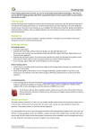
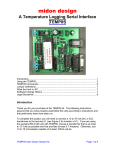
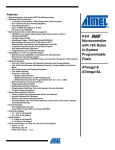
Digital boost pressure controller
Carl Wilhelmsson
791108-3934
e99cwi
“Digitala project 5p” vt 05
Abstract
This is the brief report of the development of a digital turbo boost pressure controller.
More and more of the modern cars features a turbo charger and they are often electrically
controlled from the engine control unit (ECU).
However raising the boost pressure of the turbo charger often offers a very simple way of
tuning the car. If a “boost up” is performed it is important to keep track of the actual
boost pressure, as well as controlling it accurately. It might also be interesting to perform
certain intelligent manipulation of it.
This report briefly describes prototype circuit board and prototype software that gives a
baseline for interesting boost pressure control systems.
This work has been performed as the assignment in the course “Digitala project”. For use
in an actual car extra concerns has to be taken, and the software has to be changed a bit.
Of course no claims can be held against any form of usage of this experimental setup or
the published information, neither of caused damage, nor of correctness.
-2-
Table of contents
1
Introduction.............................................................................................................- 4 1.1
System specification .......................................................................................- 4 1.2
Function and implementation .........................................................................- 4 1.2.1
Engine speed measurement.....................................................................- 4 1.2.2
Boost pressure measurement...................................................................- 5 1.2.3
Boost pressure control.............................................................................- 5 1.2.4
Boost pressure actuator ...........................................................................- 5 1.3
Possible extensions .........................................................................................- 6 2
Hardware.................................................................................................................- 6 2.1
Microcontroller ...............................................................................................- 6 2.2
LCD display ....................................................................................................- 7 2.3
“The rest” ........................................................................................................- 7 3
Software ..................................................................................................................- 8 3.1
LCD control ....................................................................................................- 8 3.2
Controller ........................................................................................................- 8 3.3
Engine speed ...................................................................................................- 9 3.4
Mail loop, user interface .................................................................................- 9 3.5
Interrupts .........................................................................................................- 9 4
Results...................................................................................................................- 10 4.1
Engine speed measurements .........................................................................- 10 4.2
AD converter, PI controller...........................................................................- 10 References.....................................................................................................................- 11 -
Table of figures
Figure 1, pin layout of the Atmel® AVR ATmega16 microcontroller ..........................- 6 -
Table of tables
Table 1, development pin connection of the ATmega16................................................- 7 Table 2, the available functions used to control the LCD display. .................................- 8 Table 3, interrupt name and application usage. ............................................................- 10 -
-3-
1 Introduction
This project started out as a lambda (the relation between actual and desired fuel amount
in an engine) measuring/logging device. But as the lambda sensor proved to need a very
difficult circitivity the project aims had to be changed for a digital boost controller (which
contains similar software as the lambda measuring device would have done).
The digital boost controller is also a very useful device, and the prototype device has
many interesting add-ons to implement.
1.1 System specification
To be useful the boost controller has to be able to control the boost pressure. This will be
obtained by using a SAAB® PWM pressure actuator which are able to “bleed” the
pressure fed to the normal metal spring operated waste-gate clock on a normal turbo car.
Using this actuator it is possible to control the boost pressure of the engine by changing
the pressure in the waste-gate clock.
The boost pressure needs to be controlled fairly accurate. The controller shall maintain
the selected pressure, that is:
•
•
•
•
The selected boost-pressure shall be maintained by controlling the waste-gate
clock pressure using the PWM output
The controller shall display four different values
o Actual current boost pressure
o Set point of desired boost pressure
o The “controller on” limit pressure
o The engine speed [rpm]
It shall be possible to change the desired “controller on” limit pressure and the
desired boost pressure
The manipulation of the set points shall be performed using two switches
o One switch increasing the set point
o One switch to decrease the set point
o If both switches is pressed simultaneously the current manipulated set
point value shall be changed
1.2 Function and implementation
The main idea it to let the ATmega16 perform all the actual work, software are
constructed to perform printouts of the desired values on the LCD display, and the other
additional components is only to provide the microcontroller with suitable input/output
facilities.
1.2.1 Engine speed measurement
To be able to measure the engine speed a TTL compatible wave form is needed from the
engine. A suitable source of this waveform would be a magnetic pickup on for example
one of the ignition cables (or some other electronic component with similar behaviour).
-4-
Because of the high impedance and sensitive nature of these systems it is not
recommendable to galvanic connect anything to the actual engine control system.
For this prototype it is assumed that the actual circitivity performing this generation of a
TTL waveform already exists, and the waveform is hence simulated with a normal
waveform generator.
The timer/counter 0 in the AVR is then set to external trig (connected to pin 1 of the
AVR), this makes the t/c 0 count every event (i.e. spark) on the TTL compatible
waveform.
The t/c 2 is also initiated, but this t/c is set to operate on the internal oscillator. If the t/c 2
is prescaled (using both software interrupt driven prescaling, and hardware prescaling) in
a suitable manner it will be a suitable time base for the engine ignition counter.
That is when the corresponding overflow interrupt arrives on t/c 2 the value of t/c 0 is
read to a global variable. Then t/c 0 is set to zero to again count the events of the engine.
The global variable then describes the number of sparks being fed to the engine during
the fix given time decided by t/c 2 prescaling. The engine speed can hence be easily
calculated and displayed on the LCD.
1.2.2 Boost pressure measurement
To be able to measure the boost pressure the internal AD converter is utilized. It is set up
as single ended measurements performing a mean average including 16 samples (since it
is possible to perform division by switching 4 bit). The AD converter is set up in a form
of “semi free run” mode, as each sample is finished a new one is started in the interrupt
routine. If 16 samples has been taken the current channel is switched using the internal
multiplexer. In this manner all eight channels is sampled and stored away in a global
vector. Even tough only one channel is used this arrangement may come in handy in the
extension applications.
1.2.3 Boost pressure control
To channel one there is a PI controller attached which is updated as soon as a new sample
is available. Note that it is due to the periodic nature of the PI controller is important that
the consecutive time between each update of the PI controller is the same every time.
For a description of the PI controller please refer to [ 4]. The details of the discretization
of the PI is totally excluded here but note that a new controller can be attached to each of
the eight AD channels in the same manner, but then more attributes has to be declared.
The PI controller shall be switched on when it is above the PI-on pressure limit. When
the pressure again falls below the PI-on limit, the state of the controller shall be zeroed
the controller shall be switched off and the controller output shall be set to zero as well.
1.2.4 Boost pressure actuator
As mentioned earlier the boost pressure actuator consists of a SAAB® PWM “bleeding
valve” this actuator can be found on many SAAB® turbo engines.
The output from the AVR to the bleeding valve is a PWM waveform. The PWM
modulation frequency shall be around 32 Hz (but probably a slightly higher frequency is
also possible to use). If an AVR frequency of 8MHz is used the t/c 1 can be set to 256
prescaling and 10bit operation to obtain (about) this frequency.
-5-
The current to the bleeding valve shall then be fed through a switching transistor, but this
analogue part has not been constructed.
1.3 Possible extensions
There are basically an infinite amount of possibilities to extend this device. The most
interesting should be a controller for the so called blow-off valve that also exists in most
turbo charged engines, and that also is a significant factor controlling the boost pressure
(but during transients).
It can also be interesting to have different driver modes, controlling boost pressure
differently depending on the desires of the driver.
2 Hardware
2.1 Microcontroller
For this application Atmega16 from Atmel
[1] is the most suitable device. This nice microcontroller contains everything you might
need to design a boost controller, given every possible ”bling bling” you might want to
implement. And it is possible to extend the features of the controller far.
In this task the main features used in the microcontroller are the AD converter and the
timer/counters.
The JTAG interface is used for debugging. After all f the desired components (such as
display and so on) are connected there still exist plenty of free inputs.
Figure 1, pin layout of the Atmel® AVR ATmega16 microcontroller
-6-
AVR pin
1
2
3
4
5
6
7
8
9
10
11
12
19
22
23
24-27
30
31
33-36
37-39
40
Usage, and connection
TTL input for ignition counter, from signal generator
LCD R
LCD R/W
LCD E
LCD DB0
LCD DB1
LCD DB2
LCD DB3
Vcc +5v
GND 0V
RXD serial com output to MAX233 pin 7
TXD serial com input to MAX233 pin8
PWM actuator output
Switch input (active low)
Switch input (active low)
JTAG communication see [ 5]
ADC voltage reference +5v (Vcc)
ADC GND
Sampled (but not connected)
Sampled not used ADC inputs, connected to trim resistor, 0-4.9V to ADC
Sampled 0-4.9V ADC, used for PI controller
Table 1, development pin connection of the ATmega16.
2.2 LCD display
To be able to visualise the measured (and controlled) boost pressure, the microcontroller
is connected to a LCD display for visualization. The selected display of use is an alpha
numeric two row 20 sign display, this for simplicity.
Software is implemented in the AVR to control the display in a suitable manner, this is
described in Software.
For the technical description of the display check the datasheet [ 2].
2.3 “The rest”
Besides the microcontroller the development board only contains two switch buttons, a
few potentiometers to experiment with the AD converter, a few resistors and
condensators to arrange with suitable power supply. The board contains the MAX233 [ 3]
used to convert RS232 to TTL levels, and a 9 pin d-sub connector to be able to connect
the board to a PC. A connection for the JTAG is also supplied.
-7-
3 Software
Here the software will be discussed briefly. No claim of a complete description of the
software is taken, only a brief description of the main functionality.
3.1 LCD control
The is a few functions needed to display characters on the display. The most difficult is
the initiation routine which has to be performed in a very precise manner.
When the routine LCDChar() is available it is possible to define a output stream and to
use the C standard “printf “ function, this is also performed, and hence complete strings
can be printed.
That is after the initiation routine the very a very simple methodology to print strings is
available:
1. Put the LCD cursor (address counter) position to the desired address (using
LCDJumpTo(x,y) )
2. Use printf function to print the desired string (using printf(“String”) )
Signature
void LCDInit(void)
void LCDClearScr(void)
void LCDJumpTo(char row,
char pos)
void LCDHome(void)
int LCDChar(char letter)
void LCDCommand(char
command)
char LCDBusy(void)
char LCDState(void)
void LCDwait(void)
Usage
LCD initiation routine, afterwards printf is available
Clear LCD screen
Move the cursor to row, col
Put the cursor to the top left position
Display the character “letter “ on the current cursor
position
Send the given command to the display
Check if the LCD is ready to receive more data
Check the address counter and the busy flag of the LCD
Wait for a long time, used in the LCDInit
Table 2, the available functions used to control the LCD display.
3.2 Controller
The software needed to perform the PI calculations is basically the same as in [ 4], it has
tough been slightly adapted to fit the environment.
When a ADC conversion complete interrupt arrives, and the PI input channel has a new
mean average value available the output of the PI controller is calculated, it is also fed to
the t/c OCR1A register for a new PWM duty cycle. Then the “update state” global flag is
arisen.
All this is performed inside the interrupt routine, but since it is important to limit the
work inside the interrupt routine the update of the integral state is performed (by a call to
PIUpdateState()) inside the main loop, and the global update flag is pulled low.
-8-
The controller consists only of a initiation routine and the update state routine (since it is
invoked in the interrupt routine and the main loop).
3.3 Engine speed
The engine speed measurement contains of the initiation routine which initiates t/c 0 and
t/c 2 for operation as described above. The t/c overflow interrupts are enabled, and when
interrupts arrive on the t/c 2 the value of t/c 0 is read out. If the t/c 0 overflow interrupt
arrives, a overflow condition has occurred, as it is now the overflow is however not
handled in any other way than setting a global flag once. To handle this in a better
manner is a possible add-on.
The visualization of the engine speed is performed in the main loop using the global
variable put away from the interrupt routines.
3.4 Mail loop, user interface
The main loop is a for(;;) loop, and it will loop forever. Inside this loop code is inserted to
handle the up/down switches (to make the increment/decrement speed reasonable the
LCDWait() routine is used to wait a short while. This will affect the controller
performance during the manipulation of the values and a better method of making the
change of these values reasonable fast is desirable, maybe a timer that is used anyway
could be used to limit the change speed.
3.5 Interrupts
As understood from before most of this applications performance is connected to the use
of interrupts, the interrupt header files defined in gcc are used. It is however important to
be careful to check the spelling when using this built in signal definitions.
Please also note that the SIGNAL(SIG_NAME) is used instead of the
INTERRUPT(SIG_NAME). This is done to avoid the interrupt to be interrupted by other
interrupts. If INTERRUPT is used it must be done with extreme real-time care. Since this
application not is very time dependant it is better to use the real-time safe SIGNAL.
Please also note that the main routine and all routines called from it can be interrupted by
a interrupt routine at ANY TIME this means that for example all of the LCD handling has
to be performed ONLY from the main routine (since the LCD data transfer is performed
in a split 4 bit mode. The resources used in the main loop can not be used in the interrupt
routines. The communication between the main loop and the interrupt routines is
performed by global variables. To make this perfect, a semaphore should be implemented
for each of the shared resources. If semaphores exists, it is possible to share resources
between the main loop and the interrupts.
-9-
Interrupt
SIG_ADC (AD complete)
SIG_OVERFLOW0
SIG_OVERFLOW2
Usage
8 channel ADC mean average of 16 samples. Update of PI
controller ch1
T/C 0 overflow, no action (too high engine speed)
T/C 2 overflow, checks the value of t/c 0 for speed
measurement
Table 3, interrupt name and application usage.
4 Results
4.1 Engine speed measurements
The resulting engine speed measurement is felt quite (too) slow. The update frequency is
not enough to be of any usage. This can depend on two things:
•
•
Since the AVR is not run in 8Mhz using the JTAG ICE the calculation of
prescaling etc is not correct.
The method of measuring the engine speed is too slow.
If a desired measurement area of 600-15000 rpm is required (as it is) frequencies between
10-250Hz should be measured. This means that the selected measuring method should be
preferable (since a 8 bit counter is used) if the counters is set so that t/c 0 is checked two
times each second a sufficient resolution should be obtained. LSB=240rpm, max
rev=61440rpm. Which should be more than enough, note that since the design is made
with a four stroke engine LSB gets quote large, by the simple reason that the ignition
pulses is slow (only one sparkplug is used).
A possible “build around” which also means a completely different solution should be to
connect the ignition pulse to an external interrupt and to have one counter to measure the
actual time. This however will probably prove to be a very noisy measurement method.
If all frequencies are selected correctly the selected method should be the best for engine
speed measurements (especially since the spark advance might be changed in between
cycles).
4.2 AD converter, PI controller
The selected usage of the AD converter proved to work very well. Eight stable and
continuously updated AD channels are hence available for any purpose.
The PI controller has not (due to lack of time) been tested on the real application. It has
tough been used to control the voltage in a capacitor with a very successful result. The PI
was able to control the control the voltage given any load disturbance with in its actuator
limitations (min and max PWM duty cycle).
- 10 -
References
[1] Atmel 8-bit AVR Microcontroller with 16K byte In-system programmable flash. Datasheet,
http://www.it.lth.se/datablad/Processors/ATmega16.pdf .
[ 2] Display unit user’s manual, Dot matrix LCD units. Datasheet,
http://www.it.lth.se/datablad/display/LCD.pdf .
[ 3] MAX232 TTL to RS232 driver. Datasheet,
http://www.it.lth.se/datablad/periphery/communication/max232-233.pdf .
[ 4] Computer Control: An Overview. Karl Johan Åström, Björn Wittenmark, Karl Erik Årzen.
IFAC paper, http://www.ifac-control.org/publications/pbriefs/PB_Wittenmark_etal_final.pdf .
[ 5] AVR060: JTAG ICE Communication Protocol. Datasheet,
http://www.it.lth.se/digp/PDF_files/avr/jtag_ice_com.pdf .
NOTE: All web references relates to the versions available 1/3 2005
- 11 -