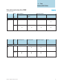
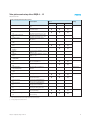
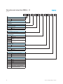
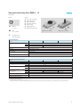
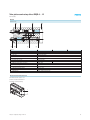
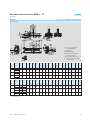
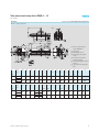
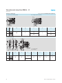
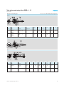
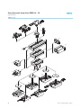
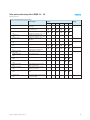
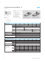
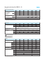
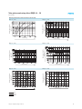
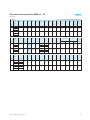
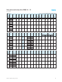
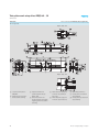
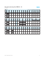
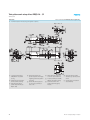
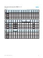
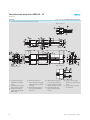
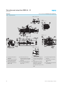
1
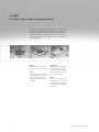
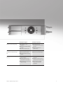
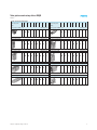
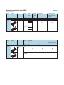
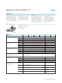
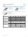
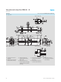
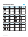
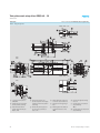
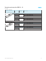
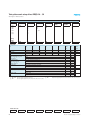
Semi-rotary drives DRQD, twin pistons
The sturdier, faster, smaller
and more powerful unit
Info 117
The DRQD:
The sturdier, faster, smaller and more powerful unit
Available with many cushioning options. For cycles rates up to 10 times faster, or
loads that are ten times heavier when using the hydraulic shock absorbers. Its
twin cylinder principle means that it is twice as precise, making it ideal for
handling and assembly tasks. As a MINI e. g. for the electronics and medical
technology industries, and as MIDI and MAXI for e.g. mechanical engineering and
production technology.
Precise,
powerful,
compact!
Powerful
Whether it is the MINI or the MAXI,
torques of 1.5 to 50 Nm are possible
Clearly defined
Adapter plates and direct mounting
are used as interfaces to grippers,
linear modules or slides. Precision
adaptation to Festo’s modular system
for handling and assembly.
Modular
Its configuration: various end position
cushioning functions, rotation and X
angle, drive shaft or mid position
module and also tubing and energy
throughfeed.
2
Reliable
Thanks to its sturdy design, standardised cylinder sensors, air connection
on 2 sides and the clever flanged
shaft throughfeed for air tubing and
sensor cables.
Info 117 – Subject to change – 2006/07
Advantages for designers
Advantages for purchasers
Modular and space-saving design
Ideal solution for every
application
Flexibility for maximum freedom
in design
Minimised installation space
Price follows function:
you only pay for the functionality
you need
Reduced acquisition and
follow-up costs
Co-ordinated interfaces for the
handling and assembly technology
kits
Minimised design complexity
Simple, reliable connections
No need for expensive in-house
solutions
Minimised ordering costs
Fast access to all required parts
All your automation technology from
one source
Use of standard cylinder sensors
SMx-8 and SMx-10
Broadest range of valves and
valve terminals on the market
Easily fitted using the appropriate
tubing and fittings
1 contact for the entire world of
pneumatics
1 delivery, 1 delivery note and 1
delivery date for the entire project
Max. operational reliability
thanks to the harmonized
components
2006/07 – Subject to change – Info 117
3
-V- New
Variants E422/E444
Twin-piston semi-rotary drives DRQD
Key features
General
Rack and pinion principle
High accuracy
Extremely good rigidity
Backlash-free and dynamic
Piston ∅ 6 … 50 mm
Torque 0.16 …50 Nm
Swivel angle 0 … 360°
End-position adjustment
–60 … +6°
Wide choice of variants
Spigot shaft
Defined interfaces
Choice of mounting options
Supply port at one end
Ideal for use in handling
applications
Flanged shaft
Piston ∅ 6 … 50 mm
Adjustable end-position cushioning
Piston ∅ 6 … 50 mm
Intermediate position
Piston ∅ 16 … 50 mm
Pneumatic
With hydraulic shock absorbers
Position sensing
Piston ∅ 16 … 50 mm
Allows positioning of the drive shaft
in a mid-position
Adapter kits for grippers and drive combinations
Piston ∅ 6 … 50 mm
For piston ∅ 6 …12 mm:
proximity sensor SME/SMT-10
For piston ∅ 16 …50 mm:
proximity sensor SME/SMT-8
Piston ∅ 6 … 50 mm
Piston ∅ 6 … 50 mm
Simple and space-saving installation of tubing through the hollow
flanged shaft
DRQD-…-SD…
1 … 4 DUO tubes
Piston ∅ 16 … 50 mm
Simple and space-saving installation of tubing and cables through
the hollow flanged shaft
DRQD-…-E…
1 … 2 DUO tubes and 2 … 4 electrical cables
Energy through-feed
Mounting options
using through holes
4
via thread in housing profile
Info 117 – Subject to change – 2006/07
Twin-piston semi-rotary drives DRQD
Features
Possible combinations with grippers
Semi-rotary drive
6
8
12
DRQD
16
20
25
Micro grippers HGPM-…-G8
32
40
50
www.festo.com
–
–
–
Parallel grippers HGP
–
–
Radial grippers HGR
Precision parallel grippers HGPP
–
–
–
2006/07 – Subject to change – Info 117
–
12
16
20
25
32
40
50
www.festo.com
–
–
–
Three-point gripper HGD
–
–
–
www.festo.com
–
Angle grippers HGW
www.festo.com
T-slot grippers HGPT
www.festo.com
–
www.festo.com
Long-stroke grippers HGPL
–
8
Micro grippers HGWM-…-G8
www.festo.com
6
–
www.festo.com
Semi-rotary drive
DRQD
www.festo.com
–
–
Parallel grippers HGPC
www.festo.com
–
–
–
–
–
5
Twin-piston semi-rotary drives DRQD
System example
System product for handling and assembly technology
1
5
4
1
5
3
3
1
4
2
4
6
Info 117 – Subject to change – 2006/07
Twin-piston semi-rotary drives DRQD
System example
System elements and accessories
Brief description
Page
1
Drive units
Wide range of combination options within handling and assembly technology
www.festo.com
2
Grippers
Wide range of combination options within handling and assembly technology
www.festo.com
3
Adapters
For drive/drive and drive/gripper combinations
www.festo.com
4
Basic mounting components
Profiles and profile connectors as well as profile/drive connectors
www.festo.com
5
Installation components
For achieving a clear-cut, safe layout for electrical cables and tubing
www.festo.com
–
Axes
Wide range of combination options within handling and assembly technology
www.festo.com
–
Motors
Servo and stepper motors, with or without gearing
www.festo.com
2006/07 – Subject to change – Info 117
7
Twin-piston semi-rotary drives DRQD
Product range overview
Function
Version
Doubleactingg
Basic version
Type
Semi-rotaryy drive
DRQD
Q
Piston ∅
Swivel
angle
[mm]
[°]
Adjustable
Position sensing
end-position
range
[°]
A
6,, 8,, 12
90
180
–20 … +6°
–60 … +6°
16,, 20,, 25,
5,
32,, 40,, 50
Function
Version
Type
yp
Piston ∅
[mm]
Doubleacting
90
180
360
0 … 340
End-position adjustment
with flexible buffers in the
end positions
J…
–
–20 … +6°
Output shaft
Spigot shaft
Flanged shaft
Integrated adapter for direct
mounting of micro grippers
ZW
FW
A…
Basic version
Semi-rotary drive
DRQD
6, 8, 12
–
16, 20, 25,
32 40
32,
40, 50
8
Info 117 – Subject to change – 2006/07
-V- New
Variants E422/E444
Twin-piston semi-rotary drives DRQD
Product range overview
Type
yp
Piston ∅
[mm]
Basic version
Semi-rotary drive
DRQD
Type of cushioning
Adjustable, pneumatic
PPVJ
Adjustable, hydraulic shock
absorbers
YSRJ
Pneumatic connection
left
right
AL
AR
6, 8, 12
–
–
–
16, 20, 25,
32, 40, 50
Type
Basic version
Semi-rotary drive
DRQD
Piston ∅
Intermediate position
Energy through-feed
[mm]
Z1
SD…, E…
Adapter kits for grippers
6, 8, 12
10
–
16, 20, 25,
32 40
32,
40, 50
26
2006/07 – Subject to change – Info 117
Page
9
Twin-piston semi-rotary drives DRQD-6 … 12
Peripherals overview
Piston ∅ 6 … 12
6
aD
aA
7
8
9
aJ
aB
2
aC
5
3
180°
1
aE
90°
bA
4
aF
bJ
aG
aI
bB
aH
10
Info 117 – Subject to change – 2006/07
Twin-piston semi-rotary drives DRQD-6 … 12
Peripherals overview
Variants, mounting attachments and accessories
Brief description
1
Centre section
2
Connector cap
3
End-position adjustment
J20
End-position adjustment
J60
Position sensing
A
Spigot shaft
ZW1)
Flanged shaft
FW1)
Flanged shaft
FW-SD32
Adapters
A082)
Adapters
A122)
Micro grippers
HGPM/HGWM
Adapters
AS1
Adapters
AS2
Standard grippers
HGP/HGD/HGR/HGW
Energy through-feed
SD32
Socket head screw
ZS
Hollow bolt
HS
Type of mounting
B1
Type of mounting
B2
Type of mounting
B3
Centring sleeve
ZBH
Rotary push-in fitting3)
QS
4
5
6
7
8
9
aJ
aA
aB
aC
aD
aE
aF
aG
aH
aI
bJ
bA
bB
1)
2)
3)
Centre section for 90° or 180° swivel
angle
With integrated compressed air
directional function
Flexible end position cushioning with
adjustable end positions (–20 … +6°)
Flexible end position cushioning with
adjustable end positions (–60 … +6°)
Contactless via proximity sensors
SME-/SMT-10
Hollow with woodruff key
Hollow
Hollow, for energy through-feed
For micro grippers HGWM-08-…-G8 and
HGPM-08-…-G8
For micro grippers HGWM-12-…-G8 and
HGPM-12-…-G8
HGPM-…-G8 and HGWM-…-G8
For standard grippers HGP-06-A,
HGR-10-A and HGW-10-A
For standard grippers HGD-16-A
HGP-06-A, HGD-16-A, HGR-10-A,
HGW-10-A
2 tubes with O.D. 3 mm
Mounting of ZW and FW
Mounting of ZW, FW, A08, A12 and air
supply for attachments
For connection of DRQD/FW-SD32:
Locking screws in centring sleeves
For connection of DRQD/FW-SD32:
Through screws in attachment
For connection of DRQD/FW-SD32:
Clamping via profile, grid 40 mm
For centring (2 pieces included in scope
of delivery for DRQD)
Quick Star push-in fittings, rotatable
with ball bearing
Piston ∅
6
Page
8
12
13
–
–
–
–
www.festo.com
–
18
63
13
www.festo.com
13
13
18
The socket head screw ZS is included in the scope of delivery. The hollow bolt HS must be ordered separately
Only in conjunction with hollow bolt HS. The hollow bolt HS must be ordered separately
For energy through-feed in combination with HS
2006/07 – Subject to change – Info 117
11
Twin-piston semi-rotary drives DRQD-6 … 12
Type codes
DRQD
—
6
— 180 — J60
—
A
— A12 —
—
HS
—
B2
—
B
Type
Double-acting
DRQD
Semi-rotary drive
Piston ∅ [mm]
Swivel angle [°]
End-position adjustment [°]
J20
J60
–20 … +6
–60 … +6
Position sensing
A
For proximity sensing
Output shaft/adapter
ZW
FW
A08
A12
AS1
AS2
Spigot shaft
Flanged shaft
Adapter
p for micro,, angle
g and parallel
p
grippers
Adapter
p for parallel,
p
, three-point,
p , angle
g and
radial grippers
Energy through-feed
SD32
2 tubes with O.D. 3 mm
Type of screw
ZS
HS
Socket head screw
Hollow bolt
Type of mounting
B1
B2
B3
Locking screws in centring sleeves
Through screws in attachment
Clamping via profile, 40 mm
User’s manual
E
F
S
I
V
B
12
German
English
French
Spanish
Italian
Swedish
Express waiver – no user manual to be
included (already available)
Info 117 – Subject to change – 2006/07
Twin-piston semi-rotary drives DRQD-6 … 12
Technical data
Function
-N-O-W-
Variants
90° and 180° swivel angle
Spigot or flanged shaft
Adapters for grippers
End-position adjustment
Position sensing
Energy through-feed
Different types of mounting
Diameter
6 … 12 mm
DRQD-8-180-J20-A-FW-ZS
Force
0.16 … 0.76 Nm
DRQD-8-180-J20-A-ZW-ZS
www.festo.com/en/
Spare_parts_service
General technical data
Piston ∅
6
Pneumatic connection
8
Assembly position
M3
M5
–
QS…-3 for tube O.D. 3 mm
Semi-rotary drive with twin pistons based on the rack and pinion principle
Flexible buffer at both ends
For proximity sensing
Via through-hole
Via female thread
Any
Operating and environmental conditions
Piston ∅
6
HS
SD32
Constructional design
Cushioning
Position sensing
Type
yp of mountingg
Operating medium
Operating
p
g ppressure
[bar]
Adjustable
j
end-position
p
range
g
[[°]]
Max. permissible
p
swivellingg
frequency
q
y at 6 bar
(for completed cycle of motion)
Repetition accuracy
Ambient temperature1)
Corrosion resistance class CRC2)
[[Hz]]
1)
2)
[°]
[°C]
SD32
J20
J60
90°
180°
SD32
8
12
12
Filtered compressed air, lubricated or unlubricated
1…8
–
1.5 … 8
–
–20 … +6
–60 … +6
5
4
3
3.5
2.5
2
–
A reduction of max. 5% of the values indicated above
< 0.2
–10 … +60
1
Note operating range of proximity sensors
Corrosion resistance class 1 according to Festo standard 940 070
Components requiring low corrosion resistance. Transport and storage protection. Parts that do not have primarily decorative surface requirements, e.g. in internal areas that are not visible or behind covers
2006/07 – Subject to change – Info 117
13
Twin-piston semi-rotary drives DRQD-6 … 12
Technical data
Forces and torques
Piston ∅
Theoretical torque
q
at 6 bar
6
[[Nm]]
SD32
Max. permissible radial and axial
forces
Max. permissible
p
mass moment [kgm2]
of inertia
8
12
0.16
–
-H-
0.33
0.76
0.28
0.72
Note: If torque acts against the direction of rotation in the end position, a drive with a rating of twice
the maximum theoretical torque should be selected.
Diagrams 17
0.075 x 10⁻⁴
0.25 x 10⁻⁴
The data applies to the variants ZW, FW, A… without grippers, unthrottled.
0.7 x 10⁻⁴
6
8
12
66
67
82
83
2
4
6
6
–
–
1
4
–
90
92
111
113
4
7
11
11
13
15
145
148
177
180
–
–
–
17
17
81
Pneumatic sizing using Pro Pneu
www.festo.com/en/engineering
Weights [g]
Piston ∅
Centre section
Output
p shaft
Adapters
p
Screws
Flanged shaft with energy
through-feed
Mountingg in combination with
SD32
14
90°
J20
J60
180° J20
J60
ZW
FW
A08
A12
AS1
AS2
ZS
HS
SD32
B1
B2
B3
5
71
18
Info 117 – Subject to change – 2006/07
Twin-piston semi-rotary drives DRQD-6 … 12
Technical data
Materials
Sectional view
1
6
7
8
3
4
2
5
Piston ∅
6
8
1
2
3
4
5
6
7
8
–
–
–
–
–
Anodised aluminium
Anodised aluminium
Anodised aluminium
Stainless steel; milled teeth
Anodised aluminium
Galvanised steel
Nitrile rubber
Nitrile rubber
Polyurethane
Steel
Stainless steel
Steel, nitrile rubber
Copper, PTFE and silicone-free
Polyurethane
Cylinder barrel (centre section)
Connector cap
Gear rack
Pinion
Piston
Threaded pin, hex nuts
Piston seal
Buffer for end-position cushioning
DUO spiral tubing
Woodruff key
Hollow bolt, centring sleeves
Static seals
Material note
12
Direction of rotation of the drive shaft
Pneumatic actuation of ports 1 or 2
produces a rotational movement in
direction R1 or R2 respectively.
1
R1
R2
2006/07 – Subject to change – Info 117
2
15
Twin-piston semi-rotary drives DRQD-6 … 12
Technical data
Max. permissible radial and axial forces on the drive shaft
Combined load
A semi-rotary drive DRQD-8-… is to be
statically loaded with a radial force
Fy = 60 N, which is at a distance of
Z = 5 mm from the housing, and an
axial force Fx, push = 30 N, which is at
a distance of V = 12 mm from the
shaft ( diagram of flanged shaft on
right).
V
Z
Question:
Answer:
Is it permissible to statically load a
semi-rotary drive DRQD-8-… with
these combined forces?
Graph 1 ( 17) indicates that the
maximum permissible radial force is
Fy, max. (stat.) (5) = 193 N for a distance
The following equation applies to combined loads:
F y (z)
F y, max. (z)
Fx (push)
Fx (pull)
Fy
+
F x, push (v)
F x, pull (v)
<
+
≤ 1
F x, push,max. (v)
F x, pull,max. (v)
Z = 5 mm. Graph 3 ( 17) indicates
that the maximum axial force is
Fx, push max. (stat.) (12) = 169 N for a
distance V = 12 mm.
The following values are assumed:
With values inserted:
Fy (5) = 60 N
Fx, push (stat.) (12) = 30 N
Fy, max. (stat.) (5) = 193 N
Fx, max. (stat.) (12) = 169 N
60 N + 30 N ≤ 1
193 N
169 N
0.311 + 0.178 ≤ 1
0.489 ≤ 1
Thus the drive may be statically
loaded with the forces indicated
above.
16
Info 117 – Subject to change – 2006/07
Twin-piston semi-rotary drives DRQD-6 … 12
Maximum static radial force
Graph 1
Fy, max. (stat.) = f(z)
Maximum dynamic radial force
Graph 2
Fy, max. (dyn.) = f(z)
Max. radial force Fy [N]
Max. radial force Fy [N]
Technical data
Distance Z [mm]
Maximum static pull and push axial forces
Graph 3
Fx, max. (stat.) = f(v)
Maximum dynamic pull and push axial forces
Graph 4
Fx, max. (dyn.) = f(v)
Max. axial force Fx [N]
Max. axial force Fx [N]
Distance Z [mm]
Distance V [mm]
2006/07 – Subject to change – Info 117
Distance V [mm]
17
Twin-piston semi-rotary drives DRQD-6 … 12
Technical data
Energy through-feed
The energy through-feed consists of
DUO tubing (two lengths of tubing are
fused together into a pair), whereby
each tube has an O.D. of 3 mm. Compressed air is supplied via the push-in
fittings in the transfer plate. Only
Quick-Star push-in fittings may be
used to connect compressed air
tubing to consuming devices
(e.g. grippers).
DRQD-…-SD…
For piston ∅ 8 … 12
Swivel angles of up to 180° are
possible
1 DUO tube
Transfer plate
Technical data
Piston ∅
Number of spiral tubes
Standard nominal flow rate
per tube
Theoretical air consumption
per tube at 6 bar
Operating
p
g pressure
p
as a function
of ambient temperature
p
Push-in fittings for connection to
consuming device
18
8
[l/min]
1 DUO tube
min. 70
[cm3]
5.3
[[bar]]
0 … 10 ((at –10 … +30
3 °C))
0 … 9 ((at +30 … +40 °C))
0 … 7 8 (at +40 … +60 °)
12
QS…-3 for tube O.D. of 3 mm
Info 117 – Subject to change – 2006/07
Twin-piston semi-rotary drives DRQD-6 … 12
Technical data
Download CAD data www.festo.com/en/engineering
Dimensions
ZW – Spigot shaft
HS
ZS
J20
1 Sensor slots for proximity
sensors SME/SMT-10
2 Supply ports
3 Mounting thread
4 Socket head screw for endposition adjustment
5 Woodruff key position at 0°
aJ Centring sleeves (2 included in
scope of delivery)
J60
∅
[mm]
6
90
180
90
180
90
180
8
12
∅
[mm]
6
8
12
1)
B1
B2
B3
B4
B5
B8
D1
∅
g7
D2
∅
g6
D31)
∅
f7
D4
D7
∅
H8
D8
∅
H8
D9
D10
∅
H7
D11
D12
EE
H1
H2
15 4
15.4
18 2
18.2
16
2
13 6
13.6
16 7
16.7
6
8
20
M2 5
M2.5
2
6
M4
7
M5
13
1.3
M3
31
68
6.8
17
22 2
22.2
20
4
16 2
16.2
20 7
20.7
8
10
22
M3
–
8
M5
9
M5
13
1.3
M3
34
88
8.8
21
22 2
22.2
20
6
18 2
18.2
20 7
20.7
8
10
22
M3
–
8
M5
9
M5
13
1.3
M3
41
88
8.8
L1
L2
L3
L4
L5
L7
L8
L9
N1
T1
T2
T3
T4
T6
T7
T8
ß1
ß2
ß3
max.
max.
46.7
61.8
54.2
71.8
59.2
76.8
20.2
27.75
23.45
32.25
25.95
34.75
71
7.1
11 1
11.1
75
7.5
20
30
62
6.2
2
12
7
18
1.8
34
3.4
16
1.6
5
14
1.4
8
25
2.5
8
81
8.1
12 1
12.1
7
–
36
57
5.7
2
16
9
–
46
4.6
2
5
2
10
3
8
91
9.1
13 1
13.1
8
–
36
57
5.7
2
16
9
–
46
4.6
2
5
2
13
4
8
Swivel
angle
[°]
Swivel
angle
[°]
90
180
90
180
90
180
±0.03 ±0.03
P9
Centring possible with D3
2006/07 – Subject to change – Info 117
19
Twin-piston semi-rotary drives DRQD-6 … 12
Technical data
Download CAD data www.festo.com/en/engineering
Dimensions
FW – Flanged shaft
HS
ZS
J20
1 Sensor slots for proximity
sensors SME/SMT-10
2 Supply ports
3 Mounting thread
4 Socket head screw for endposition adjustment
5 Position of designated threaded
hole at 0°
aJ Centring sleeves (2 included in
scope of delivery)
J60
∅
[mm]
6
8
12
∅
[mm]
6
8
12
20
Swivel
angle
[°]
90
180
90
180
90
180
Swivel
angle
[°]
90
180
90
180
90
180
B1
B2
B3
B4
B5
B6
D1
∅
D2
∅
D3
D5
∅
H7
D6
∅
g7
D7
∅
H8
D8
∅
H8
D9
D10
∅
H7
D11
D12
∅
15 4
15.4
77
7.7
4
2
13 6
13.6
15
1.5
23
16
M3
3
8
2
6
M4
7
M5
13
1.3
17
77
7.7
4
4
16 2
16.2
15
1.5
27
21
M3
3
11
–
8
M5
9
M5
13
1.3
21
77
7.7
4
6
18 2
18.2
15
1.5
27
21
M3
3
11
–
8
M5
9
M5
13
1.3
EE
H1
L1
L2
L3
L4
L5
L7
L8
L9
T3
T4
T6
T7
T8
ß1
ß2
ß3
max.
max.
46.7
61.8
54.2
71.8
59.2
76.8
20.20
27.75
23.45
32.25
25.95
34.75
71
7.1
11 1
11.1
75
7.5
20
30
62
6.2
18
1.8
34
3.4
16
1.6
5
14
1.4
8
25
2.5
8
81
8.1
12 1
12.1
7
–
36
57
5.7
–
46
4.6
2
5
2
10
3
8
91
9.1
13 1
13.1
8
–
36
57
5.7
–
46
4.6
2
5
2
13
4
8
M3
31
M3
34
M3
41
±0.03 ±0.03
Info 117 – Subject to change – 2006/07
Twin-piston semi-rotary drives DRQD-6 … 12
Technical data
Download CAD data www.festo.com/en/engineering
Dimensions
FW-SD32 – Energy through-feed
SD32
J20
1 Sensor slots for proximity
sensors SME/SMT-10
2 Supply ports
3 Mounting type B1, B2
4 Mounting type B3, dovetail
profile
5 Socket head screw for endposition adjustment
6 Position of designated threaded
hole at 0°
7 Supply port for energy throughfeed
J60
∅
[mm]
8
12
∅
[mm]
8
12
Swivel
angle
[°]
90
180
90
180
Swivel
angle
[°]
90
180
90
180
B1
B2
B3
B4
B5
B6
B7
D1
∅
D2
∅
D3
∅
D4
∅
D5
∅
H7
D6
∅
g7
D7
∅
EE
17
77
7.7
4
4
16 2
16.2
15
1.5
15
27
21
M3
3
3
11
3
M3
21
77
7.7
4
6
18 2
18.2
15
1.5
15
27
21
M3
3
3
11
3
M3
H1
H2
H3
L1
L2
L3
L4
L5
L6
L7
L8
L9
L10
L11
ß1
ß2
max.
max.
54.2
71.8
59.2
76.8
23.45
32.25
25.95
34.75
81
8.1
12 1
12.1
7
60
7
36
32
3.2
97
9.7
292
10
3
91
9.1
13 1
13.1
8
60
7
36
32
3.2
97
9.7
292
13
4
34
35
9
41
35
9
2006/07 – Subject to change – Info 117
±0.03
21
Twin-piston semi-rotary drives DRQD-6 … 12
Technical data
Download CAD data www.festo.com/en/engineering
B2 – Through screws in attachment
internal
external
Dimensions – Mounting type
B1 – Counter screws in centring sleeves
For ∅
[mm]
8
12
Swivel
angle
[°]
90
180
90
180
D11
D2
∅
h7
M4
9
L1
L2
L3
49
4.9
82
8.2
2
59
5.9
92
9.2
B3 – Clamping via profile
1 Dovetail profile
2 Profile slot
For ∅
[mm]
8
12
22
Swivel
angle
[°]
90
180
90
180
D3
H1
L4
L5
L6
L7
L8
+0.1
±0.03
10
36
5
M5
46
40
60
9
Info 117 – Subject to change – 2006/07
Twin-piston semi-rotary drives DRQD-6 … 12
Technical data
Download CAD data www.festo.com/en/engineering
Dimensions – Adapter for gripper
A08/A12
For
adapter
1
Drive
2
Grippers
3
Type of screw
A08
DRQD-6-…
DRQD-8-…
DRQD-12-…
DRQD-6-…
DRQD-8-…
DRQD-12-…
HGWM-08-…-G8
HGPM-08-…-G8
HS
HGWM-12-…-G8
HGPM-12-…-G8
HS
For
adapter
1
Drive
2
Grippers
AS1
DRQD-8-…
DRQD-12-…
HGP-06-…
HGR-10-…
HGW-10-…
HGD-16-…
A12
B1
B2
B3
±0.03
D1
D2
∅
ß1
15.2
5
13
3
99.6
M3
3
16
1.5
5
20.2
19
9
14.6
M3
3
21
1.5
5
AS1
AS2
AS2
DRQD-8-…
DRQD-12-…
2006/07 – Subject to change – Info 117
B1
B2
D1
D2
D3
D4
∅
ß1
ß2
10.2
8
M3
3
M2
M4
28
2.55
2
10.2
8
M3
3
M2
M4
299
2.55
2
23
Twin-piston semi-rotary drives DRQD-6 … 12
Ordering data – Modular products
0
M Mandatory data
Module No.
Function
Size
Swivel angle
187 431
187 432
187 433
DRQD
6
8
12
90
180
Ordering
example
187 432
DRQD
– 8
– 180
End-position
adjustment
J20
J60
– J60
Position sensing
A
– A
Ordering table
Size
6
8
12
0
M Module No.
187 431
187 432
187 433
Output shaft/
adapter
ZW
FW
A08
A12
AS1
AS2
– A12
Conditions
Function
Piston ∅
Swivel angle
g
Semi-rotary drive with twin pistons
[mm] 6
8
12
90°
180°
End-position
p
adjustment
j
Adjusting range +6°/–20°
Adjusting range +6°/–60°
Position sensing
For proximity sensing
Output
p shaft/adapter
/ p
Spigot shaft
Flanged shaft
Adapter for HGWM-08
Adapter for HGPM-08/HGWM-08
Adapter for HGWM-12
Adapter for HGPM-12/HGWM-12
–
Adapter for HGW/HGR-10-A, HGP-6-A
–
Adapter for HGD-16-A
1 ZW
3 A08, A12
Not with energy through-feed SD32
Only with screw type ZS, HS
2 FW
Only with screw type ZS, HS
24
Enter
code
DRQD
-…
-90
-180
-J20
-J60
-A
-ZW
-FW
-A08
-A12
-AS1
-AS2
DRQD
-A
Not with energy through-feed SD32
Only with screw type HS
4 AS1, AS2
Required for energy through-feed SD32
Transfer order code
DRQD
1
2
3
3
4
4
Code
Required for energy through-feed SD32
Not with screw type ZS, HS
–
–
–
– A
–
Info 117 – Subject to change – 2006/07
Twin-piston semi-rotary drives DRQD-6 … 12
Ordering data – Modular products
0
O Options
Energy through-feed
Type of screw
Type of mounting
User’s manual
SD32
ZS
HS
B1
B2
B3
E
F
S
I
V
B
– SD32
– HS
– B2
– B
Ordering table
Size
6
0
O Energy through-feed
Type
yp of screw
Type
yp of mountingg
Alternative language
g g user documentation (standard
(
is German))
5 SD32
8
12
–
2x tubing O.D. 3 mm
Socket head screw
Hollow bolt
–
Mounting type 1
–
Mounting type 2
–
Mounting type 3
English
French
Spanish
Italian
Swedish
Express waiver – no user manual to be included (already available)
6 B1, B2, B3
Only with mounting type B1, B2, B3
Conditions
Code
5
-SD32
-ZS
-HS
-B1
-B2
-B3
-E
-F
-S
-I
-V
-B
6
6
6
Enter
code
Only with energy through-feed SD32
Transfer order code
–
2006/07 – Subject to change – Info 117
–
–
–
25
Twin-piston semi-rotary drives DRQD-16 … 50
Peripherals overview
Piston ∅ 16 … 50
aD
6
aC
7
aB
2
8
5
360°
1
180°
3
90°
aE
4
aA
aJ
aD
9
aC
aB
26
Info 117 – Subject to change – 2006/07
Twin-piston semi-rotary drives DRQD-16 … 50
Peripherals overview
Variants, mounting attachments and accessories
Brief description
p
1
Centre section
2
End cap
3
Connector cap
PPVJ
Connector cap
YSRJ
4
5
6
7
8
9
aJ
aA
aB
aC
aD
aE
Centre section for 90°, 180° or 360°
swivel angle
With integrated compressed air
directional function
Flexible end position cushioning with
adjustable end positions (–20° … +6°)
Adjustable shock absorbers with
adjustable end positions (–20° … +6°)
Position sensing
A
Spigot shaft
ZW
Flanged shaft
FW
Intermediate position
Z1
Energy through-feed
SD32, SD42
Energy through-feed
SD62
Energy through-feed
SD64
Energy through-feed
SD48
Energy through-feed
E422
Energy through-feed
E444
Energy through-feed
E644
Contactless via proximity sensors
SME-/SMT-8
With woodruff key
Centring sleeve
ZBH
For centring (2 pieces included in scope
of delivery for DRQD)
2006/07 – Subject to change – Info 117
Hollow, for energy through-feed
Mid-position at centre of nominal angles
of rotation of 90° and 180° (±10°)
2 tubes with O.D. 3 or 4 mm
2 tubes with O.D. 6 mm
4 tubes with O.D. 6 mm
8 tubes with O.D. 4 mm
2 tubes with O.D. 4 mm and 1 4-pin
cable to 2 3-pin cables
4 tubes with O.D. 4 mm and 2 4-pin
cables to 4 3-pin cables
4 tubes with O.D. 6 mm and 4 3-pin
cables
Piston ∅
16
20
Page
g
25
32
40
50
–
–
–
–
–
–
–
–
–
–
–
–
–
–
–
–
–
–
–
–
–
–
–
–
–
–
60
63
60
37
38
62
27
Twin-piston semi-rotary drives DRQD-16 … 50
Type codes
DRQD
—
40
—
90
—
YSRJ
—
A
—
AR
—
FW
—
Type
Double-acting
DRQD
Semi-rotary drive
Piston ∅ [mm]
Swivel angle [°]
Type of cushioning
PPVJ
YSRJ
Adjustable end-position cushioning
Adjustable shock absorbers
Position sensing
A
For proximity sensing
Pneumatic connection
AL
AR
Supply port, left
Supply port, right
Output shaft
ZW
FW
Spigot shaft
Flanged shaft
Intermediate position
Z1
28
1 intermediate position (mid-position)
Info 117 – Subject to change – 2006/07
Twin-piston semi-rotary drives DRQD-16 … 50
Type codes
—
SD42
—
B
Energy through-feed
SD32
2 tubes with O.D. 3 mm
SD42
2 tubes with O.D. 4 mm
SD48
8 tubes with O.D. 4 mm
SD62
2 tubes with O.D. 6 mm
SD64
4 tubes with O.D. 6 mm
E422
2 tubes with O.D. 4 mm and 1 4-pin cable
to 2 3-pin cables
4 tubes with O.D. 4 mm and 2 4-pin cables
to 4 3-pin cables
4 tubes with O.D. 6 mm and 4 3-pin cables
E444
E644
User’s manual
E
F
S
I
V
B
German (standard)
English
French
Spanish
Italian
Swedish
Express waiver – no user manual to be
included (already available)
2006/07 – Subject to change – Info 117
29
Twin-piston semi-rotary drives DRQD-16 … 50
Technical data
Variants
90°, 180° and 360° or X swivel
angle
Spigot or flanged shaft
Adjustable end-position
cushioning or shock absorbers
Position sensing
Intermediate position
Energy through-feed
Different types of mounting
Function
-N-O-W-
Diameter
16 … 50 mm
Force
1.6 … 50 Nm
DRQD-20-180-YSRJ-A-AL-FW
DRQD-20-180-YSRJ-A-AL-ZW
www.festo.com/en/
Spare_parts_service
General technical data
Piston ∅
16
Pneumatic connection
SD32
SD42/SD48
E422
E444
SD62/SD64/
E644
Constructional design
Cushioningg
20
M5
QS…-3 for tubing O.D. ∅ 3 mm1)
QS…-4 for tubing O.D. ∅ 4 mm1)
QS…-4 for
tubing O.D. 4 mm
–
25
32
QS…-4 for
tubing O.D. 4 mm
–
16
Adjustable
j
end-position
p
range
Max. permissible
p
swivellingg frequency
q
y at 6 bar
((for completed
p
cycle
y of
motion))
[[bar]] PPVJ
YSRJ
Z1
[[°]]
PPVJ
YSRJ
[[Hz]] PPVJ
YSRJ
SD…/E…
30
G¼
–
–
QS…-6 for
tubing O.D. 6 mm
Operating and environmental conditions
Piston ∅
Operating medium
Operating
p
g ppressure
–
–
–
Assembly position
Position sensing
Type
yp of mountingg
50
–
Semi-rotary drive with twin pistons based on the rack and pinion principle
Adjustable, pneumatic
Adjustable, hydraulic shock absorbers
For proximity sensing
Via through-hole
Via female thread
Any
PPVJ
YSRJ
40
Gx
20
25
32
40
50
Filtered compressed air, lubricated or unlubricated
1 … 10
2 … 10
1 … 10
–20 … +6
90°
180°
360°
90°
180°
360°
4
3
2
1.2
1.2
3
2.2
1.3
0.8
0.9
1.5
1.2
0.8
0.5
0.5
2
2
1.5
1.2
1
1.8
1.8
1.5
1.2
1
1
1
0.9
0.8
0.7
A reduction of max. 5% of the values indicated above
-H- Note: At temperatures < 0 °C, a max. frequency of 1 Hz applies in the case of variant YSRJ.
1.2
0.9
0.5
0.9
0.8
0.6
Info 117 – Subject to change – 2006/07
Twin-piston semi-rotary drives DRQD-16 … 50
Technical data
Operating and environmental conditions
Piston ∅
Minimum cycle times
i conjunction
in
j ti with
ith Z1
(from the end position to
the intermediate
position)
[s]
PPVJ
YSRJ
Repetition accuracy
[°]
(approached from both
ends)
Ambient temperature
[°C]
Corrosion resistance class CRC1)
1)
16
20
25
32
40
50
0.20
0.22
0.18
0.21
0.20
0.18
180° 0.26
0.41
0.20
0.26
0.21
0.35
90°
0.20
0.22
0.17
0.20
0.47
0.35
180° 0.23
0.31
0.22
0.23
1.10
0.99
≤ 0.25
≤ 0.20
≤ 0.30
90°
≤ 0.05
≤ 0.15
Z1
–10 … +60
1
Corrosion resistance class 1 according to Festo standard 940 070
Components requiring low corrosion resistance. Transport and storage protection. Parts that do not have primarily decorative surface requirements, e.g. in internal areas that are not visible or behind covers
Forces and torques
Piston ∅
Theoretical torque
q at 6 bar
Max. permissible radial and
axial forces
Max. permissible
p
mass
moment of inertia
16
[Nm]
PPVJ
YSRJ
Z1
[[kgm
g 2] PPVJ
YSRJ
PPVJ-Z1
YSRJ-Z1
20
25
32
40
50
1.6
1.6
1.7
-H-
3.1
6.1
12.5
25
50
3.1
6.1
12.5
25
50
3.6
6.2
13.5
32.2
78.6
Note: If torque acts against the direction of rotation in the end position, a drive with a rating of twice
the maximum theoretical torque should be selected.
Graphs 35
5 x 10⁻⁴
Graphs 33
5 x 10⁻⁴
10 x 10–4
20 x 10–4
40 x 10–4
200 x 10–4
500 x 10–4
10 x 10–4
20 x 10–4
40 x 10–4
–
–
–
–
200 x 10–4
1000 x 10–4
500 x 10–4
2000 x 10–4
The data applies to the variants ZW, FW, without grippers and unthrottled.
Pneumatic sizing using Pro Pneu
www.festo.com/en/engineering
Weights [g]
Piston ∅
Connection capp AL/AR
/
Centre section/output
/ p shaft
90°
180°
360°
End cap
Intermediate pposition
PPVJ
YSRJ
ZW
FW
ZW
FW
ZW
FW
90°
Z1
180°
Z1
Flanged
g shaft with energy
gy through-feed
g
SD32
SD42
SD48
SD62
SD64
E422
E444
E644
2006/07 – Subject to change – Info 117
16
20
25
32
40
50
116
140
379
380
467
468
643
644
40
235
235
152
152
–
–
–
400
–
–
220
240
609
586
753
730
1,039
1,016
53
315
315
358
441
1,026
1,018
1,267
1,259
1,741
1,733
82
550
550
303
303
609
917
1,891
1,848
2,325
2,282
3,199
3,165
140
805
805
1,170
2,170
3,330
3,960
4,340
4,570
6,350
6,580
370
2,510
2,510
–
–
1,220
900
930
2,320
4,270
6,860
7,010
8,850
9,000
12,890
13,040
610
3,960
3,960
–
800
–
2,700
31
Twin-piston semi-rotary drives DRQD-16 … 50
Technical data
Direction of rotation of the drive shaft
Connection cap on right (AR)
Connection cap on left (AL)
Pneumatic actuation of ports 1 or 2
produces a rotational movement in
direction R1 or R2 respectively.
Pneumatic actuation of ports 1 or 2
produces a rotational movement in
direction R1 or R2 respectively.
2
1
R1
2
1
R2
R2
R1
1
2
2
1
Materials
Sectional view
1
3
8
4
7
2
5
6
Piston ∅
16
Basic drive
1 Cylinder barrel (centre section)
Anodised aluminium
2
3
4
5
6
7
–
Anodised aluminium
High-alloy stainless steel, hardened
Tempered steel
Anodised aluminium
Galvanised steel
Polyurethane
Copper, PTFE and silicone-free
Connector cap
Gear rack
Pinion
Piston
Adjustable sleeve
Piston seal
Material note
20
Function end cap PPVJ
–
Cushioning seal
–
Buffer sleeve, regulating screw
Nitrile rubber/polyurethane
Anodised aluminium
Function end cap YSRJ
–
Buffer
–
Rod wiper seal
Delrin
Nitrile rubber/polyurethane
Energy through-feed SD…/E…
–
Transfer plate/sliding disc
–
DUO spiral tubing
Anodised aluminium
Polyurethane
Z1 intermediate position module
–
Piston
–
Piston rod, nut
–
Bearings
–
Rod wiper seal
Stainless steel; nitrile rubber
Stainless steel
POM
Polyurethane
32
25
32
40
50
Wrought aluminium alloy,
anodised
High-alloy steel
Polyurethane
Info 117 – Subject to change – 2006/07
Twin-piston semi-rotary drives DRQD-16 … 50
Maximum permissible mass moments of inertia on the drive shaft
DRQD-16-…-YSRJ
DRQD-20-…-YSRJ
Mass moment of inertia
[kgm2x10-4]
Mass moment of inertia
[kgm2x10-4]
Technical data
Swivel time [s]
DRQD-32-…-YSRJ
Mass moment of inertia
[kgm2x10-4]
Mass moment of inertia
[kgm2x10-4]
DRQD-25-…-YSRJ
Swivel time [s]
Swivel time [s]
Swivel time [s]
DRQD-50-…-YSRJ
Mass moment of inertia
[kgm2x10-4]
Mass moment of inertia
[kgm2x10-4]
DRQD-40-…-YSRJ
Swivel time [s]
Swivel time [s]
90°
180°
360°
2006/07 – Subject to change – Info 117
33
Twin-piston semi-rotary drives DRQD-16 … 50
Technical data
Max. permissible radial and axial forces on the drive shaft
Combined load
A semi-rotary drive type DRQD-16-…FW is to be statically loaded with a
radial force Fy = 300 N, which is at a
distance of Z = 15 mm from the
flanged shaft, and an axial force
Fx, push = N, which is at a distance of
V = 25 mm from the shaft ( diagram
of flanged shaft on right).
V
Fx (push)
Fx (pull)
Fy
Z
V
Fx (push)
Fx (pull)
Fy
Z
Question:
Answer:
Is it permissible to statically load a
DRQD-16-…-FW semi-rotary drive with
these combined forces?
According to graph 1 ( 35), a distance of Z = 15 mm results in a maximum permissible radial force
The following equation applies to combined loads:
F y (z)
F y, max. (z)
+
F x, push (v)
F x, push,max. (v)
+
F x, pull (v)
F x, pull,max. (v)
≤ 1
Fy, max. (stat.) (15) = 400 N.
According to graph 3 ( 35), a distance of V = 25 mm results in a maxi-
mum permissible axial force
Fx, push max. (stat.) (25) = 550 N.
The following values are assumed:
With values inserted:
Fy (15) = 300 N
Fx, push (stat.) (25) = 100 N
Fy, max. (stat.) (15) = 400 N
Fx, max. (stat.) (25) = 550 N
300 N + 100 N ≤ 1
400 N
550 N
0.75 + 0.182 ≤ 1
0.932 ≤ 1
Thus the drive may be statically
loaded with the forces indicated
above.
34
Info 117 – Subject to change – 2006/07
Twin-piston semi-rotary drives DRQD-16 … 50
Maximum static radial force
Graph 1
Fy, max. (stat.) = f(z)
Maximum dynamic radial force
Graph 2
Fy, max. (dyn.) = f(z)
Max. radial force Fy [N]
Max. radial force Fy [N]
Technical data
Distance Z [mm] spigot shaft
Distance Z [mm] spigot shaft
Maximum static axial pushing force
Graph 3
Fx, push max. (stat.) = f(v)
Maximum dynamic axial pushing force
Graph 4
Fx, push max. (dyn.) = f(v)
Max. axial force Fx [N]
Distance Z [mm] flanged shaft
Max. axial force Fx [N]
Distance Z [mm] flanged shaft
Distance V [mm]
Maximum static axial pulling force
Graph 5
Fx, pull max. (stat.) = f(v)
Maximum dynamic axial pulling force
Graph 6
Fx, pull max. (dyn.) = f(v)
Max. axial force Fx [N]
Max. axial force Fx [N]
Distance V [mm]
Distance V [mm]
2006/07 – Subject to change – Info 117
Distance V [mm]
35
Twin-piston semi-rotary drives DRQD-16 … 50
Maximum static radial force
Graph 1
Fy, max. (stat.) = f(z)
Maximum dynamic radial force
Graph 2
Fy, max. (dyn.) = f(z)
Max. radial force Fy [N]
Max. radial force Fy [N]
Technical data
Distance Z [mm] spigot shaft
Distance Z [mm] spigot shaft
Maximum static axial pushing force
Graph 3
Fx, push max. (stat.) = f(v)
Maximum dynamic axial pushing force
Graph 4
Fx, push max. (dyn.) = f(v)
Max. axial force Fx [N]
Distance Z [mm] flanged shaft
Max. axial force Fx [N]
Distance Z [mm] flanged shaft
Distance V [mm]
Maximum static axial pulling force
Graph 5
Fx, pull max. (stat.) = f(v)
Maximum dynamic axial pulling force
Graph 6
Fx, pull max. (dyn.) = f(v)
Max. axial force Fx [N]
Max. axial force Fx [N]
Distance V [mm]
Distance V [mm]
36
Distance V [mm]
Info 117 – Subject to change – 2006/07
Twin-piston semi-rotary drives DRQD-16 … 50
Technical data
Z1 intermediate position module
For DRQD-16 … 50
The intermediate position module is
fitted in place of the end cap, and
allows for adjustable, backlash-free
positioning of the drive at 50% of its
nominal rotation angle. The intermediate position module is available
for nominal rotation angles of 90° and
180°.
Function
A piston incorporating two screw fastened piston rods is pressurised and
shifts the semi-rotary drive gear racks
until both make full contact with the
piston rods in the mid-position module. The mid-position can be accurately adjusted within a range of ±10°
with the adjusting screws in the piston
rods. Thanks to the hollow shaft
design of the piston rod, adjustment
can be performed under pressure. The
through rods in the mid-position
module are guided by means of
multiple bearings in the cover and in
the adapter.
Actuation
In order for the mid-position module
to function, the DRQD basic actuator
must be pressurised at both sides.
Actuation type 1
– Mid-position module (supply air
must be restricted) with a
3/2-way valve
-H-
This can be accomplished with two
different types of actuation:
– DRQD basic drive with a 5/3-way
valve, mid-position pressurised
Actuation type 2
– Mid-position module (supply air
must be restricted) with a
3/2-way valve
more than the max. permissible mass
moment of inertia for the PPVJ variant!
The reason for this is the cushioning:
Whereas loads can be absorbed in the
end positions with the shock
absorbers, the mid-position is only
equipped with basic flexible cushioning. Additional information on the
– DRQD basic drive with two
3/2-way valves, spring return
Note
Even if the semi-rotary drives
DRQD-16 to 32 have been equipped
with shock absorbers (type YSRJ), the
mid-position may not be loaded with
2006/07 – Subject to change – Info 117
permissible mass moment of inertia
for the sizes 40 and 50 mm:
31
37
Twin-piston semi-rotary drives DRQD-16 … 50
Technical data
Energy through-feed
DRQD-…-SD…
DRQD-…-E…
The energy through-feed consists of
one to max. four DUO tubes (fused
tubing pair), whereby each tube has
an O.D. of 3 … 6 mm. Compressed air
is supplied via the push-in fittings in
the transfer plate. Only Quick-Star
push-in fittings may be used to
connect compressed air tubing to
consuming devices (e.g. grippers).
The energy through-feed consists of
one to max. two DUO tubes (fused
tubing pair), whereby each tube has
an O.D. of 4 … 6 mm. Compressed air
is supplied via the push-in fittings in
the transfer plate. Only Quick-Star
push-in fittings may be used to
connect compressed air tubing to
consuming devices (e.g. grippers).
In addition, up to four proximity
sensors can be connected by means of
this energy through-feed.
DRQD-…-SD…
For piston ∅ 16 … 50
Swivel angles of up to 360° are
possible
1 … 4 DUO tubes
Transfer plate
Technical data
Piston ∅
16
Number of DUO tubes
SD32
SD42
SD48
SD62
SD64
Standard nominal flow rate
[[l/min]
/ ] SD32
(per tube))
(p
SD42
SD48
SD62
SD64
Theoretical air consumption
p
[[cm3] SD32
pper line at 6 bar
SD42
SD48
SD62
SD64
Operating
p
g pressure
p
as a func- [[bar]]
tion of ambient temperature
p
Tube O.D. on flanged
g shaft
drive side
[[mm]]
Push-in fittings for connection [mm]
to consumingg device
38
20
25
32
40
–
–
4
1
2
–
–
min. 130
min. 250
min. 250
–
–
9.5
24.4
24.4
SD32
SD42
SD48
SD62
SD64
SD32
1
1
–
–
–
min. 70
min. 130
–
–
–
5.3
9.5
–
–
–
0 … 10 ((at –10 … +30
3 °C))
0 … 9 ((at –30 … +40 °C))
0 … 7 (at –40 … +60 °)
3
4
–
–
–
QS-…-3 for tube O.D. 3 mm
SD42
QS-…-4 for tube O.D. 4 mm
–
SD48
–
SD62
–
SD64
–
QS-…-4 for
tube O.D. 4 mm
QS-…-6 for
tube O.D. 6 mm
QS-…-6 for
tube O.D. 6 mm
50
–
–
4
6
6
–
Info 117 – Subject to change – 2006/07
Twin-piston semi-rotary drives DRQD-16 … 50
Technical data
Energy through-feed
DRQD-…-E422
DRQD-…-E444
For piston ∅ 16/20
Swivel angles of up to 180° are
possible
1 DUO tube with O.D. 4 mm
1 4-pin cable to 2 3-pin cables
For piston ∅ 25/32
Swivel angles of up to 180° are
possible
2 DUO tubes each with O.D. 4 mm
2 4-pin cables to 4 3-pin cables
Transfer plate
Transfer plate
DRQD-…-E644
For piston ∅ 40/50
Swivel angles of up to 180° are
possible
2 DUO tubes each with O.D. 6 mm
4 3-pin cables
Transfer plate
Technical data
Piston ∅
16
Number of DUO tubes
E422
E444
E644
Standard nominal flow rate
[[l/min]
/ ] E422
(per tube))
(p
E444
E644
Theoretical air consumption
p
[[cm3] E422
pper line at 6 bar
E444
E644
Operating
p
g pressure
p
as a func- [[bar]]
tion of ambient temperature
p
Tube O.D. on flanged
g shaft
drive side
[[mm]]
Push-in fittings for connection [mm]
to consumingg device
2006/07 – Subject to change – Info 117
20
E444
1
–
–
min. 130
–
–
9.5
–
–
0 … 10 ((at –10 … +30
3 °C))
0 … 9 ((at +30 … +40 °C))
0 … 7 (at +40 … +60 °)
4
–
–
QS-…-4 for
tube O.D. 4 mm
–
E644
–
E422
E444
E644
E422
25
–
2
–
min. 130
–
9.5
–
4
32
40
50
–
2
–
min. 250
–
24.4
–
6
–
QS-…-4 for
tube O.D. 4 mm
–
QS-…-6 for
tube O.D. 6 mm
39
Twin-piston semi-rotary drives DRQD-16 … 32
Technical data
Download CAD data www.festo.com/en/engineering
Dimensions
ZW – Spigot shaft
DRQD-...-YSRJ-...-ZW
DRQD-...-YSRJ-...-ZW
1 T-slots for proximity sensors
SME/SMT-8
2 Self-adjusting shock absorber
for end-position cushioning
40
3 Adjustable sleeve for endposition adjustment for type
DRQD-…-YSRJ
4 Socket head screw for endposition adjustment with integral
regulating screw for end-position
cushioning
5 Variant PPVJ: both supply ports
on one end cap, optionally at
front or side
6 Variant YSRJ: Both supply ports
on one end cap, front side only
7 Woodruff key position at 0°
aJ Centring sleeves (2 included in
scope of delivery)
Info 117 – Subject to change – 2006/07
Twin-piston semi-rotary drives DRQD-16 … 32
Technical data
Dimensions
∅
Swivel
angle
[mm] [°]
16
20
25
5
332
∅
[mm]
16
20
25
5
332
∅
[mm]
16
20
25
5
332
90
180
360
90
180
360
90
180
360
90
180
360
Swivel
angle
[°]
90
180
360
90
180
360
90
180
360
90
180
360
Swivel
angle
[°]
90
180
360
90
180
360
90
180
360
90
180
360
Download CAD data www.festo.com/en/engineering
D1
D2
D3
D4
D7
D8
∅
∅
∅
∅
g6
H13
B1
B2
B3
B4
B5
B6
B7
B8
30
3
25.5
55
23
3
17.8
7
4
14.8
22
23.5
35
10
12
18
M3
3
M4
8
36
3
32.5
3
5
30
3
21.8
4
19.8
9
26
330.5
5
12
15
5
24
M4
M4
8
42
42.5
5
40
24.8
4
24.8
330
40.5
5
16
20
330
M5
5
M5
5
10
51
5
52.55
5
50
5
29.8
9
2
29.8
9
336
550.5
5
20
25
5
35
M6
M5
5
10
L1
L2
71
93
137
78.4
104.8
157.6
91.2
124
189.2
114.8
155.6
237.4
35.5
46.5
68.5
39.2
52.4
78.8
45.6
62
94.6
57.4
77.8
118.7
D9
∅
D10
D11
∅
H7
EE
H1
H2
4.2
M5
5
9
M5
5
50
5
11.2
4.2
M5
5
9
M5
5
56
5
13.5
35
5.3
5
3
M6
9
M5
5
67
7
18
5.3
5
3
M6
9
Gx
x
79
22.5
5
L10
L11
L9
±0.03
–
–
20
–
–
20
–
–
20
–
20
20
N1
L3
L4
L5
L6
L7
L8
min.
max.
min.
max.
±0.03
10
24
20.8
1.7
7
55.7
7
23.4
3
28.2
60
10
331.5
5
27
7
2.4
7
28.6
35.9
35
9
60
11
336.5
5
33
2.6
8.9
9
42
550.2
60
13
3
39
39
4.3
3
11.8
59.4
59
770.1
80
T1
T2
T3
T4
T5
T6
T7
ß1
ß2
ß3
ß4
P9
7.6
7
5.3
5
3
3
18.1
9
33.55
5
10
2
2
4
9
13
3
17
7
8
5
4
25.1
5
10
33.5
5
5
12
2
2
7
11
15
5
19
9
11
5
5
36.1
3
12.5
5
5
6
12
2
2
7
15
5
19
9
24
13.1
3
8
6
45.1
5
16
5
6
14
2
2
8
20
27
7
32
3
2006/07 – Subject to change – Info 117
41
Twin-piston semi-rotary drives DRQD-40 … 50
Technical data
Download CAD data www.festo.com/en/engineering
Dimensions
ZW – Spigot shaft
DRQD-…-YSRJ-…-ZW
DRQD-…-YSRJ-…-ZW
1 T-slots for proximity sensors
SME/SMT-8
2 Self-adjusting shock absorber
for end-position cushioning
42
3 Adjustable sleeve for endposition adjustment for type
DRQD-…-YSRJ
4 Socket head screw for endposition adjustment with integral
regulating screw for end-position
cushioning
5 Variant PPVJ: both supply ports
on one end cap, optionally at
front or side
6 Variant YSRJ: both supply ports
on one end cap, front side only
7 Woodruff key position at 0°
aJ Centring sleeves (2 included in
scope of delivery)
Info 117 – Subject to change – 2006/07
Twin-piston semi-rotary drives DRQD-40 … 50
Technical data
Dimensions
∅
Swivel
angle
[mm] [°]
40
550
∅
[mm]
40
550
∅
[mm]
40
550
90
180
360
90
180
360
Swivel
angle
[°]
90
180
360
90
180
360
Swivel
angle
[°]
90
180
360
90
180
360
Download CAD data www.festo.com/en/engineering
D2
D3
D4
D7
D8
D9
∅
∅
∅
∅
H13
B1
B2
B3
B4
B5
B6
B7
B8
D1
∅
g6
70
7
53.5
53
5
50
5
42
4
42
80
550.5
5
22
330
48.5
5
M8
M6
15
5
8.5
5
86
63.5
35
60
50
5
16
550
80
60.9
9
28
338
558.5
5
M12
M6
15
5
8.5
5
D10
D11
∅
H7
EE
H1
H2
L1
L2
L3
L4
L5
M10
15
5
Gx
x
120
24.5
5
M10
15
5
G¼
¼
144
31
3
L9
L10
N1
T1
T2
±0.03
–
–
50
–
50
100
P9
146.8
201.8
311.8
191.4
262.8
405.8
73.4
100.9
155.9
95.7
131.4
202.9
T3
L6
L7
L8
min.
max.
min.
max.
±0.03
16
49
9
41.5
5
5
14.6
85.1
5
996.4
100
18
64
55
8
20.7
7
107.8
7
120.6
100
T4
T5
T6
T7
ß1
ß2
ß3
ß4
ß6
+2
17
7
6
45.1
5
26
10
10
28
3
3
10
24
332
336
277
21.2
8
56.1
5
28
10
11
28
3
3
14
28
336
46
41
2006/07 – Subject to change – Info 117
43
Twin-piston semi-rotary drives DRQD-16 … 32
Technical data
Download CAD data www.festo.com/en/engineering
Dimensions
FW – Flanged shaft
DRQD-…-YSRJ-…-FW
DRQD-…-YSRJ-…-FW
1 T-slots for proximity sensors
SME/SMT-8
2 Self-adjusting shock absorber
for end-position cushioning
44
3 Adjustable sleeve for endposition adjustment for type
DRQD-...-YSRJ
4 Socket head screw for endposition adjustment with integral
regulating screw for end-position
cushioning
5 Variant PPVJ: both supply ports
on one end cap, optionally at
front or side
6 Variant YSRJ: both supply ports
on one end cap, front side only
7 Position of centring hole at 0°
aJ Centring sleeves (2 included in
scope of delivery)
aA Centring sleeves (not included in
scope of delivery)
Info 117 – Subject to change – 2006/07
Twin-piston semi-rotary drives DRQD-16 … 32
Technical data
Dimensions
∅
Swivel
angle
[mm] [°]
16
20
25
5
332
∅
[mm]
16
20
25
5
332
∅
[mm]
16
20
25
5
332
90
180
360
90
180
360
90
180
360
90
180
360
Swivel
angle
[°]
90
180
360
90
180
360
90
180
360
90
180
360
Swivel
angle
[°]
90
180
360
90
180
360
90
180
360
90
180
360
Download CAD data www.festo.com/en/engineering
D3
D4
D5
D6
D7
D8
∅
∅
∅
∅
H8
H7
H13
B1
B2
B3
B4
B5
B6
B7
D1
∅
D2
∅
±0.025
30
3
6.5
5
6
17.8
7
4
14.8
22
334
25
5
14
9
M4
7
M4
8
36
3
6.5
5
6
21.8
4
19.8
9
26
338
28
16
11
M4
7
M4
8
42
9.5
9
5
9
24.8
4
24.8
330
48
334
16
12
M6
9
M5
5
10
51
5
9.55
9
9
29.8
9
2
29.8
9
336
558
45
5
19
9
14
M6
9
M5
5
10
D9
∅
D10
D11
∅
H7
EE
H1
L1
L2
L3
L4
L5
71
93
137
78.4
104.8
157.6
91.2
124
189.2
114.8
155.6
237.4
35.5
46.5
68.5
39.2
52.4
78.8
45.6
62
94.6
57.4
77.8
118.7
4.2
M5
5
9
M5
5
50
5
4.2
M5
5
9
M5
5
56
5
5.3
5
3
M6
9
M5
5
67
7
5.3
5
3
M6
9
Gx
x
79
L9
L10
L11
T1
T2
T3
7.6
7
5.3
5
3
3
1.6
8
5
3
11
5
13.1
3
8
L6
L7
L8
min.
max.
min.
max.
±0.03
10
24
20.8
1.7
7
55.7
7
23.4
3
28.2
60
10
331.5
5
27
7
2.4
7
28.6
35.9
35
9
60
11
336.5
5
33
2.6
8.9
9
42
550.2
60
13
3
39
39
4.3
3
11.8
59.4
59
770.1
80
T4
T5
T6
T7
T8
ß1
ß2
ß3
ß4
33.5
5
5
10
2
2
1.4
4
9
13
3
17
7
1.6
33.5
5
5
12
2
2
1.4
7
11
15
5
19
9
3
2
5
6
12
2
2
2
7
15
5
19
9
24
3
2
5
6
14
2
2
2
8
20
27
7
32
3
±0.03
–
–
20
–
–
20
–
–
20
–
20
20
2006/07 – Subject to change – Info 117
45
Twin-piston semi-rotary drives DRQD-40 … 50
Technical data
Download CAD data www.festo.com/en/engineering
Dimensions
FW – Flanged shaft
DRQD-…-YSRJ-…-FW
DRQD-…-YSRJ-…-FW
1 T-slots for proximity sensors
SME/SMT-8
2 Self-adjusting shock absorber
for end-position cushioning
46
3 Adjustable sleeve for endposition adjustment for type
DRQD-...-YSRJ
4 Socket head screw for endposition adjustment with integral
regulating screw for end-position
cushioning
5 Variant PPVJ: both supply ports
on one end cap, optionally at
front or side
6 Variant YSRJ: both supply ports
on one end cap, front side only
7 Woodruff key position at 0°
aJ Centring sleeves (2 included in
scope of delivery)
aA Centring sleeves (not included in
scope of delivery)
Info 117 – Subject to change – 2006/07
Twin-piston semi-rotary drives DRQD-40 … 50
Technical data
Dimensions
∅
Swivel
angle
[mm] [°]
40
550
∅
[mm]
40
550
∅
[mm]
40
550
90
180
360
90
180
360
Swivel
angle
[°]
90
180
360
90
180
360
Swivel
angle
[°]
90
180
360
90
180
360
Download CAD data www.festo.com/en/engineering
D3
D4
D5
D6
D7
D8
∅
∅
∅
H7
H7
H13
B1
B2
B3
B4
B5
B6
B7
D1
∅
D2
∅
±0.025
70
7
13
3
12
42
4
42
80
80
64
330
20
M8
12
M6
155
86
133
12
50
5
16
550
80
855
64
330
24
M8
12
M6
155
D9
∅
D10
D11
∅
H7
EE
H1
L3
L4
L5
L1
L2
146.8
201.8
311.8
191.4
262.8
405.8
73.4
100.9
155.9
95.7
131.4
202.9
8.5
5
M10
15
5
Gx
x
120
8.5
5
M10
15
5
G¼
¼
144
L8
L9
L10
T1
T2
T3
T4
±0.03
±0.03
17
7
4
2.7
7
10
21.2
4
2.7
7
10
100
100
–
–
50
–
50
100
2006/07 – Subject to change – Info 117
L6
L7
min.
max.
min.
max.
16
49
9
41.5
5
5
14.6
85.1
5
96.4
9
18
64
55
8
20.7
7
107.8
7
120.6
T5
T6
T7
ß1
ß2
ß3
ß4
ß6
10
28
3
3
10
24
332
336
277
11
28
3
3
14
28
336
46
41
47
Twin-piston semi-rotary drives DRQD-16 … 32
Technical data
Dimensions
Z1 – Intermediate position module (energy through-feed is optional)
Download CAD data www.festo.com/en/engineering
DRQD-…-YSRJ-…-Z1
DRQD-…-YSRJ-…-Z1
1 T-slots for proximity sensor
SME/SMT-8 for end-position
sensing
2 Self-adjusting shock absorber
for end-position cushioning
3 Adjustable sleeve for endposition adjustment for type
DRQD-…-YSRJ
48
4 Socket head screw for endposition adjustment with integral
regulating screw for end-position
cushioning
5 Variant PPVJ: both supply ports
on one end cap, optionally at
front or side
6 Variant YSRJ: both supply ports
on one end cap, front side only
7 T-slots for proximity sensor SME/
SMT-8 for mid-position sensing
8 Socket head screw for midposition adjustment (slightly
recessed)
9 Supply port for mid-position
module at cap, optionally at side
or front
aJ Centring sleeves (2 included in
scope of delivery)
Info 117 – Subject to change – 2006/07
Twin-piston semi-rotary drives DRQD-16 … 32
Technical data
Dimensions
∅
Swivel
angle
[mm] [°]
16
20
25
5
332
∅
[mm]
16
20
25
5
332
∅
[mm]
16
20
25
5
332
90
180
90
180
90
180
90
180
Swivel
angle
[°]
90
180
90
180
90
180
90
180
Swivel
angle
[°]
90
180
90
180
90
180
90
180
Download CAD data www.festo.com/en/engineering
B12
D7
D8
D9
D10
D11
∅
∅
∅
H13
H7
B1
B2
B3
B4
B5
B6
B7
B10
B11
30
65
6.5
6
17 8
17.8
4
14 8
14.8
22
64
6.4
45
4.5
3
M4
8
42
4.2
M5
9
36
65
6.5
6
21 8
21.8
4
19 8
19.8
26
65
6.5
45
4.5
56
5.6
M4
8
42
4.2
M5
9
42
95
9.5
9
24 8
24.8
4
24 8
24.8
30
91
9.1
69
6.9
82
8.2
M5
10
53
5.3
M6
9
51
95
9.5
9
29 8
29.8
2
29 8
29.8
36
9
8
9
M5
10
53
5.3
M6
9
EE
H1
M5
50
M5
56
M5
67
Gx
79
L13
L14
L1
L2
71
93
78.4
104.8
91.2
124
114.8
155.6
35.5
46.5
39.2
52.4
45.6
62
57.4
77.8
L15
min.
max.
L4
L5
L6
L7
L8
L9
±0.03
min.
max.
min.
max.
±0.03
–
–
–
–
–
–
–
20
L10
L11
76
7.6
53
5.3
8
5
11
5
13 1
13.1
8
24
20 8
20.8
17
1.7
57
5.7
23 4
23.4
28 2
28.2
60
31 5
31.5
27
24
2.4
7
28 6
28.6
35 9
35.9
60
36 5
36.5
33
26
2.6
89
8.9
42
50 2
50.2
60
39
39
43
4.3
11 8
11.8
59 4
59.4
70 1
70.1
80
T3
T4
T5
T6
T7
ß1
ß2
ß3
ß4
ß5
52 2
52.2
12 3
12.3
0
19 1
19.1
35
3.5
5
10
2
2
4
9
13
17
3
55 4
55.4
12 3
12.3
0
21 8
21.8
35
3.5
5
12
2
2
7
11
15
19
3
62 1
62.1
15
0
26
5
6
12
2
2
7
15
19
24
4
68 2
68.2
15 5
15.5
0
31 5
31.5
5
6
14
2
2
8
20
27
32
4
2006/07 – Subject to change – Info 117
49
Twin-piston semi-rotary drives DRQD-40 … 50
Technical data
Dimensions
Z1 – Intermediate position module (energy through-feed is optional)
Download CAD data www.festo.com/en/engineering
DRQD-...-YSRJ-...-Z1
DRQD-...-YSRJ-...-Z1
1 T-slots for proximity sensor
SME/SMT-8 for end-position
sensing
2 Self-adjusting shock absorber
for end-position cushioning
3 Adjustable sleeve for endposition adjustment for type
DRQD-...-YSRJ
50
4 Socket head screw for endposition adjustment with integral
regulating screw for end-position
cushioning
5 Variant PPVJ: both supply ports
on one end cap, optionally at
front or side
6 Variant YSRJ: both supply ports
on one end cap, front side only
7 T-slots for proximity sensor SME/
SMT-8 for mid-position sensing
8 Socket head screw for midposition adjustment (slightly
recessed)
9 Supply port for mid-position
module at cap, optionally at side
or front
aJ Centring sleeves (2 included in
scope of delivery)
Info 117 – Subject to change – 2006/07
Twin-piston semi-rotary drives DRQD-40 … 50
Technical data
Dimensions
∅
Swivel
angle
[mm] [°]
40
550
∅
[mm]
40
550
∅
[mm]
40
550
90
180
360
90
180
360
Swivel
angle
[°]
90
180
360
90
180
360
Swivel
angle
[°]
90
180
360
90
180
360
Download CAD data www.festo.com/en/engineering
B11
B12
D7
D8
D9
D10
∅
∅
H13
B1
B2
B3
B4
B5
B6
B7
B10
70
7
13
3
12
42
4
42
80
992.55
9
12
M6
15
5
8.5
5
M10
86
13
3
12
50
5
16
550
80
105.7
57
9
14
M6
15
5
8.5
5
M10
D11
∅
H7
EE
H1
L1
L2
L4
L5
L8
L9
L10
±0.03
15
5
Gx
x
120
15
5
G¼
¼
144
L13
L14
146.8
201.8
311.8
191.4
262.8
405.8
L15
min.
max.
73.4
100.9
155.9
95.7
131.4
202.9
L6
L7
min.
max.
min.
max.
±0.03
49
9
41.5
5
5
14.6
85.1
5
996.4
100
64
55
8
20.7
7
107.8
7
120.6
100
–
–
50
–
50
100
177
21.2
T3
T4
T5
T6
T7
ß1
ß2
ß3
ß4
ß5
ß6
92.5
9
5
18.5
5
0
41.95
95
10
10
28
3
3
10
24
332
336
7
277
105.7
57
20.55
0
52.95
5
95
10
11
28
3
3
14
28
336
46
7
41
2006/07 – Subject to change – Info 117
51
Twin-piston semi-rotary drives DRQD-16 … 32
Technical data
Download CAD data www.festo.com/en/engineering
Dimensions
FW-SD – Energy through-feed
DRQD-…-YSRJ-…-SD…
View A
DRQD-16-… 20
DRQD-25-… 32
DRQD-…-YSRJ-…-SD…
1 T-slots for proximity sensors
SME/SMT-8
2 Self-adjusting shock absorber
for end-position cushioning
3 Adjustable sleeve for endposition adjustment for type
DRQD-…-YSRJ
52
4 Socket head screw for endposition adjustment with integral
regulating screw for end-position
cushioning
5 Variant PPVJ: both supply ports
on one end cap, optionally at
front or side
6 Variant YSRJ: both supply ports
on one end cap, front side only
7 Supply port for energy throughfeed
8 Mounting option via dovetail
profile (for ∅ 16 to 20 mm) or
profile slot nut (grid dimensions 40 mm for ∅ 25 to 32 mm)
62
9 Position of designated centring
hole at 0°
aJ Centring sleeves (2 included in
scope of delivery)
62
aA Centring sleeves (not included in
scope of delivery)
Info 117 – Subject to change – 2006/07
Twin-piston semi-rotary drives DRQD-16 … 32
Technical data
Dimensions
∅
Swivel
angle
[mm] [°]
16
20
25
5
332
∅
[mm]
16
20
25
5
332
∅
[mm]
16
20
255
332
90
180
360
90
180
360
90
180
360
90
180
360
Swivel
angle
[°]
90
180
360
90
180
360
90
180
360
90
180
360
Swivel
angle
[°]
90
180
360
90
180
360
90
180
360
90
180
360
Download CAD data www.festo.com/en/engineering
D2
D5
D6
D7
D8
D9
∅
∅
∅
∅
±0.025
H7
H13
B1
B2
B3
B4
B5
B6
B7
B8
B9
D1
∅
30
3
6.5
5
6
17.8
7
4
14.8
22
20
7
334
25
5
M4
7
M4
8
4.2
36
3
6.5
5
6
21.8
4
19.8
9
26
20
7
338
28
M4
7
M4
8
4.2
42
9.5
9
5
9
24.8
4
24.8
330
25
5
7
48
334
M6
9
M5
5
10
5.3
5
3
51
5
9.5
9
5
9
29.8
9
2
29.8
9
336
25
5
7
558
45
5
M6
9
M5
5
10
5.3
5
3
D10
∅
H13
D11
∅
H7
EE
E1
∅
H1
H3
H4
L1
L2
L3
L4
L5
71
93
137
78.4
104.8
157.6
91.2
124
189.2
114.8
155.6
237.4
35.5
46.5
68.5
39.2
52.4
78.8
45.6
62
94.6
57.4
77.8
118.7
5.5
5
5
9
M5
5
4
50
5
551
–
5.5
5
5
9
M5
5
4
56
5
551
–
6.6
9
M5
5
4
67
7
60
40
6.6
9
Gx
x
4
79
60
40
L8
L9
L10
L11
L12
L13
T2
T3
±0.03
±0.03
60
60
60
80
–
–
20
–
–
20
–
–
20
–
20
20
2006/07 – Subject to change – Info 117
L6
L7
min.
max.
min.
max.
10
24
20.8
1.7
7
55.7
7
23.4
3
28.2
10
331.5
5
27
7
2.4
7
28.6
35.9
35
9
11
336.5
5
33
2.6
8.9
9
42
50.2
5
13
3
39
39
4.3
3
11.8
59.4
59
70.1
7
T4
T6
T8
T9
ß1
ß2
ß3
ß4
min.
7.6
7
5.3
5
3
72
7
255
55
1.6
33.5
5
5
2.1
1.4
2
4
9
13
3
17
7
8
5
72
7
250
5
1.6
33.5
5
5
2.1
1.4
2
7
11
155
199
11
5
95
240
2
5
6
2.1
2
2
7
155
199
24
13.1
3
8
95
230
3
2
5
6
2.1
2
2
8
20
277
32
3
53
Twin-piston semi-rotary drives DRQD-40 … 50
Technical data
Download CAD data www.festo.com/en/engineering
Dimensions
FW-SD – Energy through-feed
DRQD-…-YSRJ-…-SD…
SD62
SD64
DRQD-…-YSRJ-…-SD…
SD48
1 T-slots for proximity sensors
SME/SMT-8
2 Self-adjusting shock absorber
for end-position cushioning
3 Adjustable sleeve for endposition adjustment for type
DRQD-...-YSRJ
54
4 Socket head screw for endposition adjustment with integral
regulating screw for end-position
cushioning
5 Variant PPVJ: both supply ports
on one end cap, optionally at
front or side
6 Variant YSRJ: both supply ports
on one end cap, front side only
7 Supply port for energy throughfeed
8 Mounting option via profile slot
nut (grid dimensions 40 mm)
62
9 Position of designated centring
hole at 0°
aJ Centring sleeves (2 included in
scope of delivery)
62
aA Centring sleeves (not included in
scope of delivery)
Info 117 – Subject to change – 2006/07
Twin-piston semi-rotary drives DRQD-40 … 50
Technical data
Dimensions
∅
Swivel
angle
[mm] [°]
40
990
180
3360
550
990
180
3360
∅
Variant
SD62/SD64
SD48
SD62/SD64
SD48
SD62/SD64
SD48
SD62/SD64
SD48
SD62/SD64
SD48
SD62/SD64
SD48
Variant
[mm]
Swivel
angle
[°]
40
990
SD62/SD64
SD48
SD62/SD64
SD48
SD62/SD64
SD48
SD62/SD64
SD48
SD62/SD64
SD48
SD62/SD64
SD48
180
3360
550
990
180
3360
∅
Variant
[mm]
Swivel
angle
[°]
40
990
SD62/SD64
SD48
SD62/SD64
SD48
SD62/SD64
SD48
SD62/SD64
SD48
SD62/SD64
SD48
SD62/SD64
SD48
180
3360
550
990
180
3360
B1
B2
B3
B4
B5
B6
B7
70
13
12
42
4
42
80
70
13
12
42
4
42
80
70
13
12
42
4
42
80
86
13
12
50
16
50
80
86
13
12
50
16
50
80
86
13
12
50
16
50
80
D9
∅
D10
∅
D11
∅
H7
EE
E1
M10
15
Gx
85
8.5
M10
15
Gx
85
8.5
M10
15
Gx
85
8.5
M10
15
G¼
85
8.5
M10
15
G¼
85
8.5
M10
15
G¼
L8
L9
6
4
6
4
6
4
6
4
6
4
6
4
85
8.5
L10
L11
H1
L12
T1
±0.03 ±0.03
B8
B9
B10
28
40
28
40
28
40
28
40
28
40
28
40
9
7.75
9
7.75
9
7.75
9
7.75
9
7.75
9
7.75
–
15.5
–
15.5
–
15.5
–
15.5
–
15.5
–
15.5
L1
L2
H3
Download CAD data www.festo.com/en/engineering
D1
D2
D3
D4
D5
D6
D7
D8
∅
∅
∅
∅
∅
∅
±0.05 H7
H7
H13
80
64
30
20
M8
12
M6
15
80
64
30
20
M8
12
M6
15
80
64
30
20
M8
12
M6
15
85
64
30
24
M8
12
M6
15
85
64
30
24
M8
12
M6
15
85
64
30
24
M8
12
M6
15
L3
L4
L5
L6
L7
min.
max.
min.
max.
120
110
146 8 73.4
146.8
73 4
16
49
41 5
41.5
5
14 6
14.6
85 1
85.1
96 4
96.4
120
110
201 8 100.9
201.8
100 9
16
49
41 5
41.5
5
14 6
14.6
85 1
85.1
96 4
96.4
120
110
311 8 155.9
311.8
155 9
16
49
41 5
41.5
5
14 6
14.6
85 1
85.1
96 4
96.4
144
110
191 4 95.7
191.4
95 7
18
64
55
8
20 7 107.8
20.7
107 8 120.6
120 6
144
110
262 8 131.4
262.8
131 4
18
64
55
8
20 7 107.8
20.7
107 8 120.6
120 6
144
110
405 8 202.9
405.8
202 9
18
64
55
8
20 7 107.8
20.7
107 8 120.6
120 6
T2
T3
T4
T5
min.
T6
T7
T8
ß1
ß2
ß3
ß4
ß6
±0.15
100
–
17
140
42
4
27
2.7
10
10
28
3
3
23
2.3
10
24
32
36
27
100
–
17
140
42
4
27
2.7
10
10
28
3
3
23
2.3
10
24
32
36
27
100
50
17
140
42
4
27
2.7
10
10
28
3
3
23
2.3
10
24
32
36
27
100
–
21 2
21.2
140
26
4
27
2.7
10
11
28
3
3
23
2.3
14
28
36
46
41
100
50
21 2
21.2
140
26
4
27
2.7
10
11
28
3
3
23
2.3
14
28
36
46
41
100
100
21 2
21.2
140
26
4
27
2.7
10
11
28
3
3
23
2.3
14
28
36
46
41
2006/07 – Subject to change – Info 117
55
Twin-piston semi-rotary drives DRQD-16 … 20
Technical data
Download CAD data www.festo.com/en/engineering
Dimensions
FW E422 – Energy through-feed
L1
for ∅ 16: 25±0.02 mm
for ∅ 20: 28±0.02 mm
56
1 T-slots for proximity sensors
SME/SMT-8
2 Plug M8x1, 4-pin
3 Socket M8x1 for proximity sensor
SME/SMT
4 Output plate can be repositioned
by 90°
5 Screw-through option with screw
M4
7 Supply port for energy throughfeed for tubing O.D. 4 mm
8 Mounting option via dovetail
connection
Info 117 – Subject to change – 2006/07
Twin-piston semi-rotary drives DRQD-25 … 32
Technical data
Download CAD data www.festo.com/en/engineering
Dimensions
FW-E444 – Energy through-feed
L1
for ∅ 25: 35±0.02 mm
for ∅ 32: 45±0.02 mm
L2
for ∅ 25: 60±0.02 mm
for ∅ 32: 80±0.02 mm
2006/07 – Subject to change – Info 117
1 T-slots for proximity sensors
SME/SMT-8
2 Plug M8x1, 4-pin
3 Socket M8x1 for proximity sensor
SME/SMT
4 Mounting via through-holes
possible with screw M5 (retaining screws must be removed
beforehand)
5 Centring hole can be
repositioned by 90°
7 Supply port for energy throughfeed for tubing O.D. 4 mm
8 Mounting option via profile slot
nut
57
Twin-piston semi-rotary drives DRQD-40 … 50
Technical data
Download CAD data www.festo.com/en/engineering
Dimensions
FW-E644 – Energy through-feed
1 T-slots for proximity sensors
SME/SMT-8
2 Plug M8x1
3 Socket M8x1
∅
[mm]
40
50
5
Swivel
angle
[°]
90
180
360
90
80
360
∅
Swivel
angle
[mm]
[°]
40
90
180
360
90
180
360
50
5
58
B1
7 Supply port for energy throughfeed for tubing O.D. 6 mm
B7
±0.2
B2
+0.4
–0.3
70
7
13
3
86
H4
40
40
B8
+0.2
–0.1
B9
80
40
9.5
9
5
12.5
5
13
3
80
40
9.5
9
5
12.5
5
L1
L2
L3
L4
146.8
201.8
311.8
191.4
262.8
405.8
73.4
100.9
155.9
95.7
131.4
202.9
B10
B11
8 Mounting option via profile slot
nut (grid dimensions 40 mm)
62
aJ Centring sleeves (2 pieces
included in scope of delivery)
62
B12
D2
∅
±0.2
D7
D8
∅
H13
D9
∅
D10
∅
D11
∅
H7
E1
∅
H1
H3
20
2.5
5
64
M6
15
5
8.5
5
M10
15
5
6
120
110
20
2.5
5
64
M6
15
5
8.5
5
M10
15
5
6
144
110
L8
L9
L11
L13
T3
T6
T7
±0.03
±0.2
L6
min.
max.
±0.03
16
49
9
5
14.6
100
18
64
5
20.7
7
100
–
–
50
–
50
50
L14
L15
L16
approx. min.
min.
L17
±0.15
140
99.5
5
64
150
5
75
88
10
3
3
140
99.5
5
65
5
130
3
75
88
10
3
3
Info 117 – Subject to change – 2006/07
Twin-piston semi-rotary drives DRQD-16 … 50
Technical data
Ordering data – Standard types
DRQD
∅
[mm]
Swivel angle
[°]
Part No.
Type
PPVJ – Adjustable end-position cushioning
AL – Connection on left
16
180
20
25
540 456
540 460
540 464
DRQD-16-180-PPVJ-A-AL-FW
DRQD-20-180-PPVJ-A-AL-FW
DRQD-25-180-PPVJ-A-AL-FW
AR – Connection on right
16
180
20
25
540 457
540 461
540 465
DRQD-16-180-PPVJ-A-AR-FW
DRQD-20-180-PPVJ-A-AR-FW
DRQD-25-180-PPVJ-A-AR-FW
AL – Connection on left
16
180
20
25
540 454
540 458
540 462
DRQD-16-180-YSRJ-A-AL-FW
DRQD-20-180-YSRJ-A-AL-FW
DRQD-25-180-YSRJ-A-AL-FW
AR – Connection on right
16
180
20
25
540 455
540 459
540 463
DRQD-16-180-YSRJ-A-AR-FW
DRQD-20-180-YSRJ-A-AR-FW
DRQD-25-180-YSRJ-A-AR-FW
YSRJ – Adjustable shock absorbers
2006/07 – Subject to change – Info 117
59
Twin-piston semi-rotary drives DRQD-16 … 50
Ordering data – Modular products
0
M Mandatory data
Module No.
Function
Size
Swivel angle
Cushioning
175 801
175 802
175 803
175 804
197 373
197 374
DRQD
16
20
25
32
40
50
90
180
360
1 … 340
PPVJ
YSRJ
DRQD
– 40
Ordering
example
197 373
– 280
– YSRJ
Position
sensing
A
Pneumatic
connection
AL
AR
– A
– AR
Ordering table
Size
16
20
25
32
40
50
0
M Module No.
175 801
175 802
175 803
175 804
197 373
197 374
32
40
50
Function
Semi-rotary drive with twin pistons
Piston ∅
[mm] 16
20
25
Swivel angle
g (standard)
(
)
90°
Adjusting
j
g range
g +6°/–20°
/
180°
(not preset)
360°
X-rotation angle
g
1° … 70°, with centre section 90°
Adjusting
j
g range
g ±6°
100° … 160°, with centre section 180°
Angle preset ±1°
190° … 340°, with centre section 360°
Cushioningg
Adjustable end-position cushioning
Adjustable shock absorbers
Position sensing
For proximity sensing
Pneumatic connection
Connection on left
Connection on right
Output
p shaft
Spigot shaft
Flanged shaft
60
2
3
Not with energy through-feed E422, E444, E644
Not with energy through-feed SD32, SD42, SD48, SD62, SD64, E422, E444, E644
Transfer order code
DRQD
–
3 FW
–
Conditions
1
2 ZW
–
ZW
FW
– FW
1
1 190 … 360
Output shaft
Code
Enter
code
DRQD
-…
-90
-180
-360
-…
-…
-…
-PPVJ
-YSRJ
-A
-AL
-AR
-ZW
-FW
DRQD
-A
Required for energy through-feed SD32, SD42, SD48, SD62, SD64, E422, E444, E644
– A
–
–
Info 117 – Subject to change – 2006/07
-V- New
Variants E422/E444
Twin-piston semi-rotary drives DRQD-16 … 50
Ordering data – Modular product system
0
O Options
Intermediate position
Energy through-feed
User’s manual
Z1
SD32
SD42
SD48
SD62
SD64
E422
E444
E644
E
F
S
I
V
B
– SD64
– B
–
Ordering table
Size
16
0
O Intermediate position
Energy
gy through-feed
g
4 Z1
25
32
1 intermediate position (mid-position)
2x tubing O.D. 3 mm
2x tubing O.D. 4 mm
–
–
–
–
–
–
–
–
–
–
–
–
2x tubing O.D. 4 mm,
1x 4-pin cable to 2x 3-pin
–
–
cable
4x tubing O.D. 4 mm,
2x 4-pin cable to 4x 3-pin
–
–
cable
–
Alternative language
g g user documentation (standard
(
is German))
20
–
–
–
40
50
–
–
–
–
8x tubing O.D. 4 mm
2x tubing O.D. 6 mm
4x tubing O.D. 6 mm
–
–
–
–
Conditions
Code
4
-Z1
-SD32
-SD42
-SD48
-SD62
-SD64
-E422
Enter
code
-E444
4x tubing O.D. 6 mm,
4x 3-pin cable
English
French
Spanish
Italian
Swedish
Express waiver – no user manual to be included (already available)
-E644
-E
-F
-S
-I
-V
-B
Cannot be combined with swivel angle (standard) 360° and X swivel angle
Transfer order code
–
2006/07 – Subject to change – Info 117
–
–
61
Twin-piston semi-rotary drives DRQD
Accessories
Ordering data
For ∅
Remarks
6
8 … 32
40/50
16 … 32
40/50
For centringg the drive on attachments
16/20
25 … 50
Design
Type
186 717
150 927
191 409
186 717
189 653
Technical data www.festo.com
ZBH-7
10
ZBH-9
ZBH-15
ZBH-7
ZBH-12
Mountingg via dovetail pprofile for variant with energy
gy through-feed
g
SD…
and E…
177 647
Technical data www.festo.com
HMSV-1
1
Mountingg via pprofile slot nut for variant with energy
gy through-feed
g
SD…
and E…
150 914
Technical data www.festo.com
NST-5-M5
1
153 526
153 529
Technical data www.festo.com
QSR-M5-4
1
QSRL-M5-4
Centring sleeve ZBH
For centringg attachments on the flanged
g shaft FW
Adapter kit HMSV
Slot nut NST
Rotary push-in fitting
6 … 12
With ball bearing,
g, for standard O.D. tubingg
Onlyy in combination with hollow
bolt HS
Straight
L-shape
16 … 32
Included in the scope of delivery if semi-rotary drive DRQD is ordered with
energy through-feed E422 and E444.
Suitable for connection of two proximity sensors SME/SMT-8 or SME/
SMT-10
544 391
Technical data www.festo.com
NEDU-M8D3-M8T4
1
16 … 32
Included in the scope of delivery if semi-rotary drive DRQD is ordered with
energy through-feed E422 and E444.
544 392
Technical data www.festo.com
NECU-M8G4
1
T-connector NEDU
Cable socket NECU
1)
PU1)
Part No.
Packaging unit quantity
Core Range
62
Info 117 – Subject to change – 2006/07
Twin-piston semi-rotary drives DRQD
Accessories
Ordering data – Proximity sensors for C-slot, magneto-resistive
Assembly
Switch
Electrical connection
output
p
Cables
M8 plug
Technical data www.festo.com
Cable length
Connection
direction
Part No.
Type
In-line
In-line
Lateral
In-line
525 915
525 916
526 675
173 220
173 218
SMT-10F-PS-24V-K2,5L-OE
SMT-10F-PS-24V-K0,3L-M8D
SMT-10F-PS-24V-K0,3Q-M8D
SMT-10-PS-SL-LED-24
SMT-10-PS-KL-LED-24
Connection
direction
Part No.
Type
525 914
525 913
526 672
173 212
173 210
SME-10F-DS-24V-K0,3L-M8D
SME-10F-DS-24V-K2,5L-OE
SME-10F-ZS-24V-K2,5L-OE
SME-10-SL-LED-24
SME-10-KL-LED-24
[m]
N/O contact
Insertable from
above
PNP
3-wire
–
–
33-pin
p
2.5
0.33
Insertable from
end
PNP
–
3-wire
3-pin
–
0.3
2.5
Technical data www.festo.com
Ordering data – Proximity sensors for C-slot, magnetic reed
Assembly
Electrical connection
Cable length
Cables
M8 plug
[m]
–
3-wire
2-wire
–
3-wire
3-pin
–
0.3
2.55
In-line
In-line
3-pin
–
0.3
2.5
In-line
Connection
Cable length
[m]
Part No.
Type
yp
N/O contact
Insertable from
above
Insertable from
end
Technical data www.festo.com
Ordering data – Plug sockets with cable
Assemblyy
Switch output
PNP
Straight plug socket
M8 union nut
Angled plug socket
M8 union nut
NPN
33-pin
p
2.5
5
159 420
159 421
SIM-M8-3GD-2,5-PU
SIM-M8-3GD-5-PU
33-pin
p
2.5
5
159 422
159 423
SIM-M8-3WD-2,5-PU
SIM-M8-3WD-5-PU
Part No.
Type
yp
M12 plug
Cable length
[m]
SMT-8F-PS-24V-K2,5-OE
SMT-8F-NS-24V-K2,5-OE
SMT-8F-ZS-24V-K2,5-OE
SMT-8F-PS-24V-K0,3-M8D
SMT-8F-NS-24V-K0,3-M8D
SMT-8F-PS-24V-K0,3-M12
SMT-8-PS-K-LED-24-B
Ordering data – Proximity sensors for T-slot, magneto-resistive
Assemblyy
Switch output
p Electrical connection
Cables
M8 plug
Technical data www.festo.com
N/O contact
Insertable from
above
Insertable from
end,, flush with
the cylinder
profile
PNP
NPN
–
PNP
NPN
PNP
PNP
3-wire
3
–
–
2.5
5
2-wire
–
–
33-pin
p
–
–
2.5
0.3
3
–
3-wire
–
–
3-pin
–
0.3
2.5
525 898
525 909
525 908
525 899
525 910
525 900
175 436
–
3-pin
–
0.3
175 484
SMT-8-PS-S-LED-24-B
3-wire
–
–
7.5
525 911
SMT-8F-PO-24V-K7,5-OE
N/C contact
Insertable from
above
PNP
Core Range
2006/07 – Subject to change – Info 117
63
Twin-piston semi-rotary drives DRQD
Accessories
Ordering data – Proximity sensors for T-slot, magnetic reed
Assemblyy
Electrical connection
Cables
Technical data www.festo.com
M8 plug
Cable length
[m]
Part No.
Type
yp
525 895
525 897
525 907
525 896
150 855
SME-8F-DS-24V-K2,5-OE
SME-8F-DS-24V-K5,0-OE
SME-8F-ZS-24V-K2,5-OE
SME-8F-DS-24V-K0,3-M8D
SME-8-K-LED-24
N/O contact
Insertable from
above
Insertable from
end,, flush with
the cylinder
profile
3-wire
3
–
2-wire
–
3-wire
–
3-pin
–
2.5
5.0
2.5
0.3
2.5
–
3-pin
0.3
150 857
SME-8-S-LED-24
3-wire
–
7.5
525 906
SME-8F-DO-24V-K7,5-OE
Connection
Cable length
[m]
Part No.
Type
yp
2.5
5
2.5
5
159 420
159 421
159 428
159 429
SIM-M8-3GD-2,5-PU
SIM-M8-3GD-5-PU
SIM-M12-3GD-2,5-PU
SIM-M12-3GD-5-PU
2.5
5
2.5
5
159 422
159 423
159 430
159 431
SIM-M8-3WD-2,5-PU
SIM-M8-3WD-5-PU
SIM-M12-3WD-2,5-PU
SIM-M12-3WD-5-PU
Part No.
Type
yp
151 680
ABP-5-S
N/C contact
Insertable from
above
Ordering data – Plug sockets with cable
Assemblyy
Switch output
PNP
Straight plug socket
M8 union nut
M12 union nut
Angled plug socket
M8 union nut
M12 union nut
Ordering data – Slot cover for T-slot
Assemblyy
Length
[m]
Insertable from
above
2x 0.5
Technical data www.festo.com
NPN
33-pin
p
33-pin
p
33-pin
p
33-pin
p
Core Range
64
Info 117 – Subject to change – 2006/07
What must be observed when using Festo components?
Specified limit values for technical
data and any specific instructions
must be adhered to by the user in
order to ensure recommended operating conditions.
When pneumatic components are
used, the user shall ensure that they
are operated using correctly prepared
compressed air without aggressive
media.
When Festo components are used in
safety-oriented applications, the user
shall ensure that all applicable
2006/07 – Subject to change – Info 117
national and local safety laws and
regulations, for example the machine
directive, together with the relevant
references to standards are observed.
Unauthorised conversions or modifications to products and systems from
Festo involve a safety risk and are
thus not permissible.
Festo does not accept any liability for
resulting damages.
You should contact Festo’s advisors if
one of the following apply to your
application:
The ambient conditions and conditions of use or the operating medium differ from the specified
technical data.
The product is to perform a safety
function.
A risk or safety analysis is required.
You are unsure about the product’s
suitability for use in the planned
application.
You are unsure about the product’s
suitability for use in safety-oriented
applications.
All technical data applies at the time
of going to print.
All texts, representations, illustrations
and drawings included in this catalogue are the intellectual property of
Festo AG & Co. KG, and are protected
by copyright law.
All rights reserved, including translation rights. No part of this publication
may be reproduced or transmitted in
any form or by any means, electronic,
mechanical, photocopying or otherwise, without the prior written permission of Festo AG & Co. KG. All
technical data subject to change
according to technical update.
65
Products and services – everything from a single source
Products incorporating new ideas are
created when enthusiasm for technology and efficiency come together.
Tailor-made service goes without
saying when the customer is the focus
of attention.
Pneumatic and electrical drives
Valves and valve terminals
Compressed air preparation
Pneumatic cylinders
Semi-rotary drives
Handling modules
Servopneumatic positioning
systems
Electromechanical drives
Positioning controllers and
controllers
Standard valves
Universal and applicationoptimised valves
Manually and mechanically
actuated valves
Shut-off, pressure control and flow
control valves
Proportional valves
Safety valves
Service unit combinations
Filter regulators
Filters
Pressure regulators
Lubricators
On-off and soft-start valves
Dryers
Pressure amplifiers
Accessories for compressed air
preparation
Fieldbus systems/
electrical peripherals
Fieldbus Direct
Installation system CP/CPI
Modular electrical terminal CPX
Components
Customer-specific solutions
Modules
Industry-specific solutions
Systems
Services from Festo to increase your productivity – across the entire value creation sequence
< Engineering – for greater speed in
the development process
CAD models
14 engineering tools
Digital catalogue
FluidDRAW®
More than 1,000 technical
consultants and project engineers
worldwide
Technical hotlines
66
< Supply chain – for greater speed in
the procurement process
E-commerce and online shop
Online order tracking
Euro special manufacturing service
Logistics optimisation
Info 117 – Subject to change – 2006/07
Gripping and vacuum technology
Sensors and monitoring units
Controllers/bus systems
Accessories
Vacuum generators
Vacuum grippers
Vacuum security valves
Vacuum accessories
Standard grippers
Micro grippers
Precision grippers
Heavy-duty grippers
Proximity sensors
Pressure and flow sensors
Display and operating units
Inductive and optical proximity
sensors
Displacement encoders for
positioning cylinders
Optical orientation detection and
quality inspection
Pneumatic and electropneumatic
controllers
Programmable logic controllers
Fieldbus systems and accessories
Timers/counters
Software for visualisation and data
acquisition
Display and operating units
Pipes
Tubing
Pipe connectors and fittings
Electrical connection technology
Silencers
Reservoirs
Air guns
All in all, 100% product and service quality
A customer-oriented range with unlimited flexibility:
Components combine to produce ready-to-install modules and
systems. Included in this are special designs – since at Festo, most
industry-specific products and customer-specific solutions are based
on the 23,000 plus catalogue products. Combined with the services
for the entire value creation sequence, the end result is unbeatable
economy.
< Assembly – for greater speed in the
assembly/commissioning process
Prepack
Preassembly
Turnkey pneumatics
Handling solutions
2006/07 – Subject to change – Info 117
< Operation – for greater speed in the
operational process
Spare parts service
Energy saving service
Compressed air consumption
analysis
Compressed air quality analysis
Customer service
67