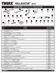
1
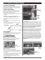
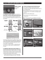
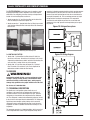
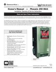
INSTALLER’S & OWNER’S MANUAL
INSTALLER: PLEASE LEAVE MANUAL FOR HOMEOWNER
Designed For Basement and Crawl
Space Dehumidification
n
n Includes
installation, operating
and safety instructions, warranty
information
n Read
and save these instructions
Rev 2012-01
TABLE OF CONTENTS
Table of Contents
WARNING!
1. Precautions....................................................................................... 2
2. Intended Application.......................................................................... 2
3. Specifications.................................................................................... 2
4. Electrical Requirements..................................................................... 3
5. Installation Location........................................................................... 3
6. Unit Assembly................................................................................... 3
6.1 Installing Feet............................................................................ 3
6.2 Attaching Drain Hose................................................................. 3
6.3 Condensate (Water) Removal..................................................... 4
6.4 Condensate (Water) Removal Using Condensate Pump.............. 4
7. Operation........................................................................................... 5
7.1 Fan (blower) Control................................................................... 5
7.2 Humidity Control Adjustment...................................................... 5
8. Defrost Cycle..................................................................................... 5
9. Maintenance...................................................................................... 5
9.1 Air Filter..................................................................................... 5
9.2 Cleaning and Replacement........................................................ 5
9.3 Removing Filters........................................................................ 6
9.4 Installing Filters.......................................................................... 6
10. Service............................................................................................ 6
11. Technical Description...................................................................... 6
12. Troubleshooting............................................................................... 7
— This symbol
means important instructions. Failure to heed them can
result in serious injury or death.
CAUTION!
— This symbol
means important instructions. Failure to heed them can
result in injury or property damage.
2. Intended Application
The DezAir is intended for installation in residential crawl spaces
that experience short or long-term high humidity conditions;
however, this attractively designed unit can be placed in almost any
indoor residential setting where dehumidification is desired. The
DezAir is not intended to be used in indoor pool rooms.
This unit is designed to operate in temperatures between 40°F
and 95°F. Temperatures outside of these ranges may affect
dehumidifier performance.
In order to efficiently control the humidity levels, the area in which
the dehumidifier is to be placed must be free of water intrusion
or excessive fresh (outside) air infiltration. Before installing, water
intrusion and air infiltration problems should be addressed for
maximum unit performance.
Condensate Pump Installation Instructions............................................. 4
Filter Installation Instructions................................................................. 6
Wiring Diagram...................................................................................... 6
Service Parts List................................................................................... 7
Exploded Parts Diagram........................................................................ 8
Optional Equipment............................................................................... 9
Warranty.............................................................................................. 10
3. Specifications
Model:DEZ-1100
Air Circulation:
300 CFM
Power:
700 watts @ 80°F and 60% RH
Supply Voltage:
115V–1phase–60 Hz
Current Draw:
6.4 Amps
• Always use a 115VAC grounded outlet.
Energy Factor: 2.90 L/kWh
• Never operate electrical equipment near or in standing water.
Operating Temp.: 40°F Min., 95°F Max.
• Do not stick your fingers or other objects through the safety grills.
Sized for:
1. Precautions
• Do not operate the unit with a cut or frayed power cord.
• Do not unplug the unit by pulling on the cord. Grasp the plug firmly and pull it out of the wall socket or power receptacle.
18,000 Cubic Ft. - Typical
Minimum Performance at 80°F and 60% RH
Water Removal:
109 Pints/Day
Efficiency:
6.1 Pints/kWh
• Do not restrict airflow into or out of the unit. This may cause the unit to overheat.
Air Filter:
MERV-11
Efficiency:Standard 65% Efficient, ASHRAE Dust Spot Test
Size:
15-3/4” x 10-1/4” x 1”
• Unit should never be serviced or cleaned while it is plugged in.
• Do not sit or stand on the unit or use as a shelf or table.
• Before leaving the unit unattended, ensure children do not have access to the equipment. Do not allow children to play with or near the unit or in its air flow.
Power Cord:
10', 110-120 VAC, Ground
Drain Hose:
9/16” ID x 3/4”OD x 8'Direct Gravity Drain Hose
Dimensions
UnitShipping
Width:
20"
22 1/4"
Height:
15"
16 1/8"
Depth:
37 1/4"
39 3/16"
Weight: 86lbs99lbs
• The DezAir is designed to be installed indoors only.
Read the installation, operation and maintenance instructions
carefully before installing and using this unit. Proper adherence
to these instructions is essential to obtaining maximum
efficiency from your dehumidifier.
Standard: This unit conforms to UL STD 474 and CSA standard C22.2 No. 92
Read and Save These Instructions
2
DezAir Installer’s & Owner’s Manual
DezAir INSTALLER'S AND OWNER'S MANUAL
4. Electrical Requirements
The DezAir plugs into a common 115 VAC grounded outlet on a
15-Amp circuit. Use of a ground fault circuit interrupter (GFCI)
protected circuit is recommended.
Figure 2:
Insert leveling
feet in locations
5. Installation location
The DezAir can be installed in a variety of locations to meet
the owner’s needs, but should be installed in the area to be
dehumidified. Other considerations include:
1. Providing access to a 115 VAC power outlet (10’ power cord is provided).
Figure 2a:
Screw each
leveling
foot in ten
revolutions
2. Installing near a floor or other suitable drain (8’ drain hose included). If this is not possible, refer to section 6.4.
3. Do not operate in standing water or place the unit near open water.
4. Do not install the unit with the exhaust directed at a wall or other obstruction.
6.2 Drain Hose: Two drain ports are provided; one on each side.
Both drain ports have rubber plugs installed. Remove the plug
from the drain port to be used. Place drain hose on the end of the
chosen drain port until fully seated on drain port. Secure hose to
the drain port with clamp. Be sure to leave the remaining drain
plug in the drain port, that is not going to be used. Refer to
Figures 3 and 4 regarding proper drainage.
5. Do not place the unit where curtains or debris can be drawn into the intake and restrict airflow.
Air In
Unit Air Flow
The DezAir drains via a gravity system. A level indicator has been
included near the exhaust of the unit. To ensure the unit will drain
properly, the level indicator bubble should be positioned in the
center area of the level indicator as shown. Refer to Figure 6.
Air Out
6. Unit Assembly
If the unit is placed on an uneven surface, adjust all four feet
underneath the unit until bubble in the level dial is in the correct
center position. Failure to level the unit may result in leakage or
improper drainage. Be sure the unit is high enough to gravity
drain and all four leveling legs are touching the ground after
the center of the leveling bubble is correctly located within
the leveling indicator. See Section 6.3 regarding drain hose
installation.
6.1 Installing Feet Included with your unit are four leveling
feet. It is important to level the unit for proper draining. See
Section 5 Installation Location
CAUTION!
Note: Do not lay unit on its side at any time.
If unit is inadvertently laid on its side, turn upright for a
minimum of 15 minutes before operating.
Figure 1:
Four leveling feet
Figure 3:
Drain port
Installing Leveling Feet
See Figures 2 and 2a for installing leveling feet.
1. With unit sitting upright on floor, lift right-hand side of unit and screw in both leveling feet on right-hand side approximately 10 revolutions.
Figure 4:
Drain hose position
2. Lift left-hand side of unit high enough to thread remaining two feet into bottom of base approximately 10 revolutions.
Clamp
3. Level unit for proper drainage as described in section 6.3 (Figure 6) of this manual.
3
DezAir Installer’s & Owner’s Manual
DezAir INSTALLER'S AND OWNER'S MANUAL
Figure 6: Level bubble
should be in indicator
area for proper
drainage.
2. Position the condensate pump so the discharge line from the unit can be shortened and placed into the condensate pump. Measure the distance from the drain port to the condensate pump leaving enough length to install the hose into the condensate pump.
3. Cut the provided ¾“ discharge hose long enough to reach the condensate pump. Cut ¾” hose end at a 45-degree angle on one end.
4. Place cut end into condensate pump.
6.3 Condensate (Water) Removal: The unit drains via a
gravity system - it is not able to push condensate (water) uphill.
The drain hose must run flat or downhill toward the drain location.
Be sure the hose is not kinked or otherwise restricted so that
water can pass through it. Improper hose installation may result in
water leakage.
5. Run discharge line from condensate pump to the discharge area.
DezAir Condensate Pump Installation Instructions
Condensate Pump Kit
STEP 1
STEP 2
STEP 3
Figure 7: Drain hose position
Figure 8: Optimum hose position for draining
To increase the efficiency of the unit, position the hose to create a
“trap” as shown in Figure 8. By creating a trap, it will hold a small
amount of water. Position the trap on the hose approximately 12”
to 20” away from the unit. Check hose regularly to ensure it is
clear and water is draining properly.
If a floor drain is not easily accessible, a condensate pump kit
with a 20’ hose is available. Refer to 6.4 Condensate pump
installation.
STEP 4
STEP 5
6.4 Condensate pump installation (OPTIONAL) In the
event that a gravity drain directly from the unit is not available, a
separate condensate pump is needed. In order to use a separate
condensate pump, the DezAir will need to be raised up on blocks
in order to maintain the gravity feed out of the DezAir and into the
condensate pump for proper condensate removal.
1. Position DezAir onto blocks to raise unit to maintain gravity feed of condensate discharge from unit. Ref. 6.2 drain hose.
4
DezAir Installer’s & Owner’s Manual
DezAir INSTALLER'S AND OWNER'S MANUAL
8 Defrost Cycle
7. Operation
An automatic defrost temperature sensor is attached to the
refrigerant tubes inside the unit. It will automatically shut the
compressor off if excessive frost forms on the evaporator coil.
The blower will continue to run, causing air to flow through the
evaporator coil and melt the ice. When the ice has melted, the
evaporator temperature will rise and the defrost temperature
sensor will automatically restart the compressor. During the
defrost cycle process, the compressor will not be running and cool
air may be coming out of the unit.
7.1 Fan Control “UNIT OFF” means no power is supplied to
the unit. It will not operate.
“Fan runs all the time to circulate air” means fan runs always,
compressor runs only as required to maintain humidity set point.
This function is desirable if the unit is used for air circulation or
filtration.
“Fan only runs when dehumidifier is on” (Recommended
setting) means the fan and compressor run together as required
to maintain humidity set point. Once humidity set point is reached
the whole unit will shut off until the relative humidity rises and
further dehumidification is needed.
9. Maintenance
CAUTION!
7.2 Humidity Control Adjustment The humidity control
allows the humidity setting to be adjusted to obtain the required
humidity level. The humidity control tells the dehumidifier when
to dehumidify. Dehumidification will take place when the relative
humidity (RH) of the air in which the dehumidifier is located rises
to the dial set point. Dehumidification will stop when the RH drops
5% below the set point.
NOTE: Do not operate the unit without the proper filter or
with a less effective filter. The heat exchange coils inside the
unit could become clogged, resulting in premature failure
of refrigeration components, a loss of effectiveness and/or
efficiency, which may require total disassembly to clean.
9.1 Air Filter The DezAir ships with a standard MERV-11
65% 1” pleated fabric filter and a 1/4” aluminum framed pre-filter
installed. Operating the unit with a dirty or obstructed filter will
reduce dehumidifier capacity and efficiency and may cause the
compressor to cycle on and off unnecessarily.
9.2 Filter Cleaning & Replacement Check filters every
six months or more frequently depending on room conditions.
Clean and/or replace when filters are visibly dirty. See cleaning
instructions below. For replacement filters, call 1-800-640-1500.
Figure 9: Dial shown in recommended position
Figure 11: Pre-filter
rinsed in Water, mesh
side up
Approximate Humidity Levels Per Setting
“Drier” 35% to 45% Relative Humidity
“Normal” 45% to 55% Relative Humidity(Recommended for most
applications)
“Humid” 55% to 65% Relative Humidity
The 1/4” washable
pre-filter should not be
discarded.
The dehumidifier will run continuously until the relative humidity
(RH) is reduced to the humidity control dial setting. There is
no benefit to setting the humidity control to “drier” in rooms
under 65°F; doing so will result in long periods of ineffective
dehumidifier run time.
Inspect the pre-filter for
debris, dirt, or other obstructions at the same time the 1” pleated
fabric filter is checked. Wash the 1/4” pre-filter every time the
1” pleated fabric filter is replaced. To clean the 1/4” pre-filter,
remove filter from the unit, ref. section 9.3, rinse the 1/4”prefilter in water with the water flowing through the aluminum
support mesh side. Refer to Figure 11. Allow the pre-filter to
dry completely before reinstalling. Reinstall the filters per the
instructions in section 9.4 Installing Filters.
Once the dial has been set to the desired level of humidity control,
the unit will maintain the same percentage of relative humidity
regardless of room temperature.
To turn the unit off, you can set the “Fan Control” to “UNIT OFF”,
or you can position the humidity control to the far left and set fan
control to “Fan only runs when dehumidifier is on”.
CAUTION!
CAUTION!
NOTE: Failure to follow filter installation instructions may
result in improper function of the dehumidifier and cause
premature component failure.
When the compressor stops running for any reason it will not
restart for 3 minutes. When it starts, it will run for a minimum
of 5 minutes regardless of the % RH setting.
5
DezAir Installer’s & Owner’s Manual
DezAir INSTALLER'S AND OWNER'S MANUAL
9.3 Filter Removal Check filters every six months or more
frequently depending on room conditions. Clean and/or replace
when filters are visibly dirty. See filter cleaning and replacement
Section 9.2 and installing filters section 9.4.
operation. A flooded evaporator should maintain constant pressure
and temperature across the entire coil, from inlet to outlet. The
mixture of gas and liquid refrigerant enter the accumulator after
leaving the evaporator coil. The accumulator prevents any liquid
refrigerant from reaching the compressor. The compressor
evacuates the cool refrigerant gas from the accumulator and
compresses it to a high pressure and temperature gas to repeat
the process.
1. Gently remove the 1/4” pre-filter by pulling on the side of the filter and sliding the filter to the right or left.
2. Gently remove the 1” pleated fabric filter by lifting it up on both ends and then sliding the filter to the right or the left removing it from the unit.
Figure 13: Refrigeration system.
Figure 12: Removing and installing filter
Figure 14: Wiring diagram.
9.4 Installing Filters
1. Gently slide 1” pleated filter into filter slot until it falls into the recess in the cover. Do not force. If resistance is felt, check alignment for obstructions or debris inside the filter housing. Be sure main filter is seated all the way in the opening.
2. Gently slide 1/4” pre-filter along the top of the 1” pleated filter. Do not force. If resistance is felt, check alignment for obstructions or debris inside the filter housing.
10. Service
WARNING!
Servicing the unit with its high - pressure refrigerant system
and high - voltage circuitry presents a health hazard which
could result in death, serious bodily injury, and/or property
damage. Only qualified service people should service this unit.
For Service call 1-800-640-1500.
11. Technical Description
The DezAir uses a refrigeration system similar to an air
conditioner’s to remove heat and moisture from incoming air
and add heat to the air that is discharged. Hot, high - pressure
refrigerant gas is routed from the compressor to the condenser
coil. The refrigerant is cooled and condensed by giving up its heat
to the air that is discharged from the dehumidifier. The refrigerant
liquid then passes through capillary tubing, which causes the
refrigerant pressure and temperature to drop. It next enters the
evaporator coil where it absorbs heat from the incoming air and
evaporates.
The evaporator operates in a flooded condition, which means that
all the evaporator tubes contain liquid refrigerant during normal
6
DezAir Installer’s & Owner’s Manual
DezAir INSTALLER'S AND OWNER'S MANUAL
12 Troubleshooting
“Fan only runs when dehumidifier is on” mode:
Blower and compressor do not run.
1. Unit unplugged or no power to outlet, circuit breaker tripped
2. Humidity control set too high
3. Loose connection in internal wiring
4. Humidity control is defective
4.a. The unit will continue to run at a default setting
of 50% RH.
5. Humidity sensor defective or not connected properly.
5.a. The unit will continue to run and will perform a defrost cycle as required.
In either mode:“Fan runs all the time” or
“Fan only runs when dehumidifier is on” with
“Humidity Control” turned to ON, blower runs but
compressor does not.
1. In a defrost cycle, ambient temperature too low
2. Loose connection in compressor circuit
3. Defective compressor overload
4. Defective compressor or compressor
run capacitor
“Fan runs all the time”mode: Blower runs but
compressor cycles on & off.
1. Low ambient temperature and/or humidity causing unit to cycle through defrost mode
2. Cold coil sensor is defective or loose. The unit will continue to run and will perform a defrost cycle every 53 minutes of operation.
3. Defective compressor overload
4. Defective compressor
5. Low refrigerant charge
In either mode:“Fan runs all the time” or “Fan
only runs when dehumidifier is on”: Blower does
not run but compressor runs briefly but cycles on
and off.
1. Loose connection in blower circuit
2. Obstruction preventing blower impeller rotation
3. Defective blower
4. Defective mode switch
Evaporator coil frosted continuously, low
dehumidifying capacity.
1. Dirty air filter or air flow restricted
2. Cold coil sensor is defective or loose. The unit will continue to run and will perform a defrost cycle every 53 minutes of operation.
3. Low refrigerant charge
Warm air discharging from unit.
This is normal while dehumidifying.
If none of the above has fixed the issue, call the
service department at 1-800-640-1500
Replacement Parts For more information on the
DezAir, call 1-800-640-1500
DezAir SERVICE PARTS LIST • To order, 1-800-640-1500
#Accessory Name QTY(PC)Specifications/Material
1
Pre-filter
1
Aluminum,mesh,foam
2
Main air filter
1
MERV-11-1”thick
3
Humidity control switch knob
1
ABS
4
Fan control switch knob
1
ABS
5
Control panel label
1
PVC
6 Cover1 LLDPE
7
Line cord 1
105℃ 300V 16AWG*3,125V 13A
8
control box cover
1
Galvanized steel sheet
9
PCB control system
1
115V/60Hz
10
Fan control switch 1
250V/25A
11Potentiometer1 0-2.2KΩ,4W
12
Potentiometer bracket
1
Galvanized steel sheet
13
Compressor capacitor
1
35μF/250V
14
Control box bracket
1
Galvanized steel sheet
15
Wire guard grommet
4
Rubber
16
Control box 1
Galvanized steel sheet
17
Fan guide 1
Steel sheet Spray plastics
18
Fan 1
Aluminum alloy
19
Fan guard
1
Steel
20
Fan housing
1
Steel sheet Spray plastics
21
Anti-vibration gasket
1
Rubber
22
Fan capacitor
1
12.5μF/250V
23
Fan motor
1
115V/60HZ
24
Cable clamp
1
Flame-resisting ABS
25Level1
26
Compressor rubber grommet 3
Rubber
Steel
27 Compressor rubber grommet bolt sleeve3
28
Compressor
1 5RS072UBA21 115V/60Hz R410A
29
Over-load protector
1
B290-150-241H
30
Gasket terminal cover
1
EPT
31
Terminal cover
1
EPT
32
Terminal cover gasket
1
EPT
33
Nut-terminal cover
1
M5-Steel
34
Condenser
1
Al,Cu and steel
35
Condenser cover
1
Galvanized steel sheet
36
Rating label
1
Polyester adhesive
37
Heat exchanger
1
PP
38
Humidity sensor
1
39
Left bracket
1
Galvanized steel sheet
40
Right bracket
1
Galvanized steel sheet
41
Evaporator
1
Al,Cu and steel
42
Water tray
1
Stainless steel
43
Defrost temperature sensor
1
44
Air flow guide part I
1
Galvanized steel sheet
45
Air flow guide part II
1
ABS
46
Air flow guide part III
1
ABS
47
Capillary tube
2
2.5*1.0
48
Suction tube
1
9.52*0.8 Copper Tube
49
Fill Valve
1
50
Insulation 1
PE
51
Condenser tube
2
9.52*0.8 Copper Tube
52Filter/dryer1
53
Process tube
1
6.35*0.8 Copper Tube
54
Discharge tube
1
6.35*0.8 Copper Tube
55
Drain fitting I
1
Nylon
56
Drain fitting II
1
Nylon
57
Base
1
LLDPE
58
Drain plug
2
Rubber
59
Leveling feet
4
Rubber/steel
7
DezAir Installer’s & Owner’s Manual
DezAir SERVICE PARTS LIST
• To order, 1-800-640-1500
Exploded View
8
DezAir Installer’s & Owner’s Manual
DezAir Optional Equipment
DezAir Exhaust Duct Ring Kit (Optional)
Other optional equipment:
An Exhaust Duct Ring kit is available for situations when the unit
needs to be located outside of the area where humidity needs to
be addressed.
Condensate Pump Kit - Reference section 6.4
Installation:
1. Slide the duct ring, from the top down, into slots provided in
the cover located at the exhaust end of the unit. Make sure the
Exhaust Duct Ring is seated all the way down in slots.
Exhaust end
Slots in cover for Exhaust Duct Ring
Optional Equipment and Filters
To order optional equipment for the DezAir, call
888-236-7231
2. Connect the flexible duct hose to the Exhaust Duct Ring.
Connect
flexible hose
3. Position grille and sheet metal duct flange accordingly to
exhaust to proper location.
4. Connect flexible duct hose to sheet metal duct flange.
Note: Some installations do not require the use of a grille or sheet
metal duct flange.
9
DezAir Installer’s & Owner’s Manual
DezAir Limited Warranty
Limited Warranty. Basement Systems, Inc. (“BSI”) warrants as
follows: (i) the DezAir dehumidifier (“Product”) will be free of material
defects in workmanship or materials for a period of twenty four
months following the date of purchase of the unit.
What IS COVERED: This warranty extends only to the original residential
end-user of the DezAir, and may not be assigned or transferred.
This warranty does not include indoor pool, spa or hot tub applications.
FIRST AND SECOND YEAR WARRANTY: BSI warrants that, for two (2)
years the DezAir will operate free from any defects in materials ```and
workmanship, or BSI will, at its option, repair or replace the defective
part(s), free of any charge.
THIRD THROUGH FIFTH YEAR WARRANTY: BSI further warrants that
for a period of five (5) years, the condenser, evaporator, and compressor
of the DezAir will operate free of any defects in material or workmanship,
or BSI, at its option, will repair or replace the defective part(s), provided
that all labor and transportation charges for the part(s) shall be borne by
the end-user.
End user agrees to change the pleated filter on an annual basis, and
purchase the replacement filters from BSI, or the warranty will be void.
Limitation of Remedies. CUSTOMER’S SOLE AND EXCLUSIVE
REMEDY UNDER THE ABOVE LIMITED WARRANTY AND BSI’S
ENTIRE LIABILITY THEREUNDER, SHALL BE, AT THE SOLE OPTION
OF BSI, REPLACEMENT OR REPAIR OF SUCH PRODUCT OR ITS
COMPONENTS (“COMPONENTS”) BY BSI OR BSI’S AGENTS ONLY. IF
TRANSPORTATION IS REQUIRED TO BASEMENT SYSTEMS’ SERVICE
CENTER, CUSTOMER MUST PAY FOR SUCH TRANSPORTATION TO
AND FROM BASEMENT SYSTEMS. THIS DISCLAIMER AND EXCLUSION
SHALL APPLY EVEN IF THE EXPRESS WARRANTY AND LIMITED
REMEDY SET FORTH HEREIN FAILS OF ITS ESSENTIAL PURPOSE.
CUSTOMER ACKNOWLEDGES THAT NO REPRESENTATIVE OF BSI OR
OF ITS AFFILIATES OR RESELLERS IS AUTHORIZED TO MAKE ANY
REPRESENTATION OR WARRANTY ON BEHALF OF BSI OR ANY OF ITS
AFFILIATES OR RESELLERS THAT IS NOT IN THIS AGREEMENT.
Disclaimer of Warranties. EXCEPT FOR ABOVE LIMITED
WARRANTY, WHICH IS THE SOLE AND EXCLUSIVE WARRANTY
PROVIDED WITH RESPECT TO THE PRODUCT AND ITS COMPONENTS,
BSI HEREBY DISCLAIMS ALL EXPRESS AND IMPLIED WARRANTIES,
INCLUDING, WITHOUT LIMITATION, THE IMPLIED WARRANTIES OF
MERCHANTABILITY AND FITNESS FOR A PARTICULAR PURPOSE.
Warranty Limitations. A “defect” under the terms of the limited
warranty shall not include problems resulting from Customer’s
or Customer’s employees’, agents’, invitees’ or a third party’s
misuse, improper installation, improper design of any system in
which the Product is included, abuse, lack of normal care, failure to
follow written instructions, tampering, improper repair, or freezing,
corrosion, acts of nature or other causes not arising out of defects
in BSI’s workmanship or material. If a Product or Component is
replaced while under warranty, the applicable limited warranty
period shall not be extended beyond the original warranty time
period. The limited warranty does not cover any costs related to
changes to a Product or Component that may be required by any
codes, laws, or regulations that may become effective after initial
purchase of the Product by Customer.
Customer Responsibilities. As a further condition to obtaining
warranty coverage hereunder, the Customer must send a valid
warranty claim to BSI such that BSI receives such claim prior to the
end of the applicable warranty period. BSI shall have no obligation
hereunder with respect to any claim received by BSI after the
expiration of the applicable warranty period. Warranty service must
be performed by BSI or a servicer authorized by BSI. In order to
obtain warranty service, the Customer should call BSI at 1-800640-1500 and ask for the BSI Products Service Department, which
will then arrange for applicable warranty service. Warranty service
will be performed during customary, daytime working hours. If
the Product must be shipped for service, Customer shall be solely
responsible for properly packaging the Product, for all freight
charges, and for all risk of loss associated with shipment.
Limitation of Liability. IN NO EVENT SHALL BSI, IN CONNECTION
WITH THE DESIGN, SALE, INSTALLATION, USE, REPAIR,
REPLACEMENT OR PERFORMANCE OF ANY PRODUCT, COMPONENT,
PART THEREOF OR WRITTEN MATERIAL PROVIDED THEREWITH,
BE LIABLE, TO THE EXTENT ALLOWED UNDER APPLICABLE LAW,
UNDER ANY LEGAL THEORY FOR ANY SPECIAL, DIRECT, INDIRECT,
COLLATERAL OR CONSEQUENTIAL DAMAGES OF ANY KIND.
NOTWITHSTANDING THE ABOVE LIMITATIONS AND WARRANTIES,
THE SOLE AND EXCLUSIVE LIABILITY OF BSI, REGARDLESS OF
THE NATURE OR THEORY OF THE CLAIM, SHALL UNDER NO
CIRCUMSTANCES EXCEED THE PURCHASE PRICE OF THE PRODUCT,
COMPONENT OR PART UPON WHICH THE CLAIM IS PREMISED.
Applicable Law and Venue. ANY ARBITRATION, ENFORCEMENT
OF AN ARBITRATION OR LITIGATION RELATED TO THE PRODUCT
WILL BE BROUGHT EXCLUSIVELY IN NEW HAVEN COUNTY,
CONNECTICUT, AND CUSTOMER CONSENTS TO THE JURISDICTION
OF THE FEDERAL AND STATE COURTS LOCATED THEREIN, SUBMITS
TO THE JURISDICTION THEREOF AND WAIVES THE RIGHT TO
CHANGE VENUE. CUSTOMER FURTHER CONSENTS TO THE EXERCISE
OF PERSONAL JURISDICTION BY ANY SUCH COURT WITH RESPECT
TO ANY SUCH PROCEEDING.
Miscellaneous. If any term or condition of this Limited Warranty
is found by a court of competent jurisdiction to be invalid, illegal or
otherwise unenforceable, the same shall not affect the other terms
or conditions hereof or thereof or the whole of this Limited Warranty.
Any delay or failure by BSI to exercise any right or remedy will not
constitute a waiver of BSI to thereafter enforce such rights.
Basement Systems, Inc.
60 Silvermine Road
Seymour, Connecticut 06483
1-800-640-1500
Information in this document is subject to change without notice.
No part of this document may be reproduced or transmitted in any
form or by any means, electronic or mechanical, for any purpose,
without the express written permission of Basement Systems.
© 2013 Basement Systems, Inc. All rights reserved.
10
DezAir Installer’s & Owner’s Manual