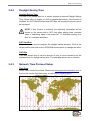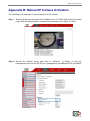
1
Network Video Recorder XIP – NVR04 LION User’s Manual Version 1.3 NVR User’s Manual Caution and Preventive Tips Handle with care, do not drop the unit Mount the unit in an equipment rack or place it on a solid, stable surface. Indoor use only. Do not place the unit in a humid, dusty, oily, or smoky site. Do not place it in an area with poor ventilation or in an area close to fire or other sources of heat. Doing so may damage the unit as well as cause fire or an electric shock. When cleaning is necessary, shut down the system and unplug the unit from the outlet before uncovering the top cover. Do not use liquid cleaners or aerosol cleaners. Use only a damp cloth for cleaning. Always shut down the system prior connecting or disconnecting accessories, with the exception of USB devices. This symbol intends to alert the user to the presence of important operating and maintenance (servicing) instructions in the literature accompanying the appliance. This symbol intends to alert the user to the presence of unprotected “Dangerous Voltage” within the product’s enclosure that may be strong enough to cause a risk of electric shock. 1 NVR User’s Manual Important Information Before proceeding, please read and observe all instructions and warnings in this manual. Retain this manual with the original bill of sale for future reference and, if necessary, warranty service. When unpacking your unit, check for missing or damaged items. If any item is missing, or if damage is evident, DO NOT INSTALL OR OPERATE THIS PRODUCT. Contact your dealer for assistance. WARNING RISK OF EXPLOSION IF THE RTC BATTERY ON THE MAINBOARD IS REPLACED WITH AN INCORRECT TYPE. DISPOSE THE USED BATTERIES ACCORDING TO THE INSTRUCTIONS. 2 NVR User’s Manual Table of Contents 1. Overview ....................................................................................................................... 6 2. System Setup ................................................................................................................ 7 2.1 Position the Unit ..................................................................................................... 7 2.2 Connect Devices to the Unit ................................................................................... 7 2.3 Front Panel LEDs ................................................................................................... 8 2.4 Rear Panel Connectors .......................................................................................... 8 3. General System Setup ............................................................................................... 10 3.1 USB Mouse Operation.......................................................................................... 11 3.1.2 Functional Keys ......................................................................................... 11 3.2 Enter OSD Setup Menu ........................................................................................ 13 3.2.1 User Management ..................................................................................... 13 3.3 Reboot and Shutdown .......................................................................................... 15 3.3.1 HDD Auto Scan.......................................................................................... 16 3.4 System Date/time Setting ..................................................................................... 17 3.4.1 Set Date/time ............................................................................................. 17 3.4.2 Daylight Saving Time ................................................................................. 18 3.4.3 Network Time Protocol Setup .................................................................... 18 3.5 IP Camera Setting ................................................................................................ 19 3.5.1 IP Camera Information ............................................................................... 20 3.5.2 Connection Setup ...................................................................................... 22 3.5.3 Device Setup ............................................................................................. 24 3.5.4 Activated .................................................................................................... 24 3.5.5 Status ......................................................................................................... 24 3.5.6 Copy Settings ............................................................................................ 25 3.6 Record Schedule/Quality Setting .......................................................................... 26 3.6.1 3.6.2 3.6.3 3.6.4 3.6.5 3.6.6 3.6.7 3.6.8 Schedule Setup ......................................................................................... 26 Preset Record Configuration ..................................................................... 27 Advance Schedule Setup .......................................................................... 27 Data Lifetime Setup ................................................................................... 29 Circular Recording ..................................................................................... 30 Audio Recording ........................................................................................ 30 Purge Data................................................................................................. 30 Pre-Alarm Recording ................................................................................. 31 4. NVR Operation ............................................................................................................ 32 4.1 View Live/Playback Videos ................................................................................... 32 4.1.1 Viewing Modes .......................................................................................... 32 3 NVR User’s Manual 4.1.2 Digital Zoom............................................................................................... 32 4.1.3 IP Camera Info........................................................................................... 33 4.1.4 Sequence Display (8CH Models Only) ...................................................... 33 4.1.5 Playback Recorded Videos ........................................................................ 33 4.2 Search Recorded Video ....................................................................................... 34 4.2.1 Search by Time .......................................................................................... 35 4.2.2 Calendar Search ........................................................................................ 35 4.2.3 Search by Event ........................................................................................ 36 4.3 Video Export ......................................................................................................... 37 4.3.1 OSD Export Menu...................................................................................... 37 4.3.2 Quick Video Export .................................................................................... 39 4.4 Dome Control ....................................................................................................... 40 4.4.1 PTZ Controlling Buttons ............................................................................. 40 4.4.2 Set Preset Points ....................................................................................... 42 4.4.3 Call Preset Points ...................................................................................... 42 4.4.4 Run Dome Camera Tour ............................................................................ 43 4.5 UPnP Function ..................................................................................................... 43 4.5.1 Setting Up the NVR and the PC................................................................. 43 4.5.2 UPnP NAT Traversal Function ................................................................... 44 4.6 System Log Exportation ....................................................................................... 44 5. Remote Monitoring Software ..................................................................................... 45 5.1 Remote Monitoring System Requirements ........................................................... 45 5.2 Software Installation ............................................................................................. 46 5.2.1 Change Internet Settings ........................................................................... 46 5.2.2 Install Remote Monitoring Software ........................................................... 49 5.2.2.1 Log in/Log off................................................................................ 50 5.2.2.2 Software Upgrades ....................................................................... 51 5.3 Basic Operation for Monitoring Remotely ............................................................. 51 5.3.1 View Live Video ......................................................................................... 51 5.3.1.1 Select Display Mode..................................................................... 52 5.3.1.2 Operate Cameras with Dome Control .......................................... 52 5.3.1.3 Digital Zoom of Camera Display ................................................... 53 5.3.2 Instant Recording....................................................................................... 54 5.3.2.1 Record Video Instantly ................................................................. 54 5.3.2.2 Playback Instant Recorded Video ................................................ 54 5.3.3 Playback Video .......................................................................................... 54 5.3.3.1 Playback Remote Video ............................................................... 55 5.3.3.2 Playback Local *.drv Files ............................................................ 56 5.3.3.3 Playback Controls ........................................................................ 56 5.3.4 Verify Digital Signature .............................................................................. 57 4 NVR User’s Manual 5.3.5 Search from Event List .............................................................................. 57 5.3.6 Take a Snapshot ........................................................................................ 58 5.3.7 Health Status of HDD ................................................................................. 58 5.3.8 Normal and Dual Streaming ....................................................................... 59 5.3.9 Remote Software Upgrade/ Reboot of Connected NVR ............................ 59 5.3.10 Remote Monitoring Software Troubleshooting ........................................... 60 Appendix A: Keyboard Access Sketch .......................................................................... 62 Appendix B: Manual IP Camera Activation .................................................................... 63 5 NVR User’s Manual 1. Overview The XIP – NVR04 LION is a premium network video recorder that combines the features of a time-lapse audio / video recorder, a multiplexer, and a video server to create a single security solution. The XIP – NVR04 LION is equipped with Power over Ethernet (PoE) ports that eased the connection to IP cameras with just one single cable covering power and network sources. The Plug and Play function helps users to automatically setup IP cameras once they are connected. IP cameras will be set to provide dual streaming to the NVR for recording and live monitoring. In addition, the Full HD (1080P) video at local monitor display presents high quality images. The XIP – NVR04 LION is pre-installed with remote viewing and configuration software, which is a Web-browser plug-in allowing users to view live or recorded video images, and enables remote configuration. The remote software is stored in the XIP – NVR04 LION and deployed over a LAN, WAN or Internet connection to remote Windows-based computers. This simplifies the installation and maintenance of the software components so all remote users are using the same software coming from the unit. In addition, the central management software and smart phone applications also provide convenience to monitor at anywhere and anytime. 6 NVR User’s Manual 2. System Setup The notices and introduction on system installation will be described particularly in this chapter. Please follow the description to operate the unit. In order to prevent the unit from data loss and system damage that caused by a sudden power fluctuation, use of an Uninterruptible Power Supply (UPS) is highly recommended. 2.1 Position the Unit Firstly, note to position/mount the NVR in a proper place and be sure to power off the unit before making any connections. The placed location should avoid hindering or blocking the unit from airflow. Enough airflow is needed to protect the unit from overheating. The maximum allowable temperature of operating environment is 40°C. The unit utilizes heat-conducting techniques to transfer internal heat to the case, especially to the bottom side of the unit. NOTE: Be sure the rubber feet are not removed, and always leave a space for air ventilation on the unit’s bottom side. 2.2 Connect Devices to the Unit This section lists some notices that should be given before making any connections to the NVR. Connecting Required Devices Before powering on the unit, cameras, a main monitor and a USB mouse should be connected to the unit for basic operation. Connecting Short-term Device If any short-term devices shall be installed to the NVR as parts of the unit system, such as USB ThumbDrive® or any USB devices, etc., make sure those devices are connected only after the unit is powered on. The reason is that the NVR can recognize the external devices only after the power-on process is done completely. 7 NVR User’s Manual 2.3 Front Panel LEDs The LEDs on the front panel of the NVR are described as follow. Network LED The LED lights up when the NVR is connected to a network and blinks when data is being transferred. REC LED The LED blinks while the NVR is recording. Alarm LED The LED lights up when an alarm is triggered. 2.4 Rear Panel Connectors There are various connectors on the rear panel for the NVR installations. The connectors are described as the followings. Audio Out The NVR provides an Audio Out port for connection to an audio output device, such as an amplified speaker. VGA The VGA connector is for connection to a VGA monitor. HDMI The HDMI connector is for connection to a HDMI monitor that transfers data digitally to deliver the best display quality. 8 NVR User’s Manual e-SATA (Optional) Users can connect an e-SATA storage device to expand the storage size of the NVR. Note that this port is only available for 4CH models. NOTE: The NVR MUST be shutdown before detaching the e-SATA storage device. LAN (RJ-45) The NVR is capable of networking and it allows videos to be viewed over the LAN network or the internet via the IE browser. USB Connectors The USB connectors are provided for users to connect external USB devices to the unit, such as ThumbDrive®, or an USB mouse. PoE Ports Each PoE port is for direct connection to an IP camera to provide power and network with just one RJ-45 cable. Power Jack Connect the power supply cord and the power adaptor shipped with the NVR. NOTE: Use of other power supply cords or power adaptors may cause overloading. 9 NVR User’s Manual 3. General System Setup Before operating the NVR, some general configuration should be setup first. The following subsections will introduce general configuration of the NVR. The regular displayed OSD information and its displayed positions are shown as the following figure. Title of the channel will be displayed on the top-center of the gird, either in full-screen mode or in multiple-window mode. The current operation status and date/time information will be displayed in the status bar at the bottom of the screen. Move the cursor to any status bar icon and its description will be displayed. Refer to the Setup Guide for a list of status bar icons and their descriptions. CH1 CH3 CH2 CH4 2013/12/09 04:31:22 PM 10 NVR User’s Manual 3.1 USB Mouse Operation A USB mouse must be connected in order to operate the NVR. As shown in the figure on the right, click the left button to select or “ENTER”. Conversely, click the right button to exit or “ESC”. The scroll wheel is for adjusting values. NOTE: Users can setup preferred mouse sensitivity level by accessing the OSD menu <Monitor> <Mouse Sensitivity>. Users can click and drag on any camera name to change its position. When right clicking on any camera name, options are provided for setting positions of all camera names at once. In addition, users can also connect an USB keyboard to help operating the NVR. Refer to the appendix for key definition of the USB keyboard. 3.1.2 Functional Keys Move the cursor to the right side of the screen and a Live Panel will be displayed. This section describes the functional icons in the Live Panel. Please refer to the Setup Guide for the graphical illustration of the functional icons. ENTER/ZOOM In Live full-screen mode, click on this icon to view a 2× zoom image. ESC Click on this icon to logout. MODE Click on this icon repeatedly to change the display format among full-screen, 4-window, and 9-window. Refer to section Viewing Modes for more information. 11 NVR User’s Manual FREEZE Click on this icon while viewing live image, the live video will be frozen. The date/time information shown on the monitor will continue updating, as well as the recording of video. Click on this icon again to return to live video of the current moment. SEARCH In Live mode, click on this icon to enter the Search menu to search and playback recorded video by date/time or event. PLAY Click on this icon to playback recorded video from last suspend time. NOTE: The video of latest 5~10 minutes cannot be played back because the video is still saved in the buffer. SEQ (Sequence) This icon is for automatic sequence display of predetermined camera orders. NOTE: This function is only available for 8CH models. MENU Click on this icon to enter the OSD setup menu. DOME Click on this icon to enter Dome Camera Control mode. Please refer to Section Dome Control for detailed controlling operation. CHANNEL In Live mode, click on the CHANNEL icons to view the corresponding video in full-screen. NOTE: Users can also right click the mouse, and the pop-up menu provides some similar functions such as Mode List, Mode, Freeze, Search, Fast PB, Sequence, Menu and Dome. 12 NVR User’s Manual 3.2 Enter OSD Setup Menu The configuration of the NVR can be customized through the intuitive Graphical User Interface (GUI) OSD setup menu. Collaborating with a USB mouse, setting up the NVR can be easy as operating on a PC. Click on the MENU icon in the Live Panel and select an account to login. The next step is to enter a corresponding password. The preset password for the administrator account “admin” is “1234”. NOTE: It is strongly suggested to change the preset password to prevent unauthorized access to the unit. An icon displayed at the status bar will show the authority level of the account. Under logout condition, the icon will be a guest icon. When an account is logged in, its authority level number (1~8) will be shown. Before completely logout, other functions can still be accessed. There are two ways to logout: manually logout by clicking on the ESC icon in the Live Panel, or auto logout when users have not accessed the NVR for a preset period of time (default 5 minutes) at Live/Menu mode. 3.2.1 User Management The NVR provides the option to create up to seven sets of usernames and passwords with customized authority, excluding the preset “admin” account. From the Main Menu, select <System> <User Management> and the menu is as the following. User Management Password Protection Auto Logout Account Setup Permissions Setup Load Default Setting On 300 Sec No Password Protection Select <On> to request username and password for accessing functions listed in Authority Setup menu, or select <Off> to allow free access. 13 NVR User’s Manual Auto Logout Select the duration of time to auto logout after no operation is performed. Account Setup Setup customized account, password, and privilege level in this menu. The account is case sensitive. The privilege level rank from level 1~8, and level 8 has highest privilege. Alternatively, select <Disable> to stop using the account. A second password can also be specified, if required. NOTE: The username and privilege level of the preset administrator account “admin” cannot be changed. Permissions Setup Setup the allowed authority level for accessing the functions listed in this menu. In accordance with users’ privilege level defined in <Account Setup>, the authority level here also ranks from levels 1~8, with level 8 as the highest level. Users will be able to access any function that is set to their equivalent or lower level. Alternatively, select <DISABLE> to allow free access. NOTE: The “Menu Access” cannot be set to <Disable>. When the account does not have authority to access certain functions, an error message will be displayed on the screen. Load Default Setting Select <Yes> to load the default setting. 14 NVR User’s Manual 3.3 Reboot and Shutdown If the NVR must be shutdown for any reason, please follow the proper shutdown procedures to avoid damaging the NVR. Click on the Menu icon and users can either choose <Shutdown> to quick shutdown the NVR, or choose <Menu> to enter the Shutdown menu. The following menu will be displayed. Shutdown Power Off Reboot Auto Rebooting Rebooting Time Off AM 12:00 Power Off Select this item to shutdown the NVR. Do not remove the power source until the NVR is completely off. Reboot Select this item to reboot the NVR. The login screen will be displayed after the NVR is completely restarted. Auto Rebooting The NVR can be set to reboot automatically once a day/week at a predetermined time, in order to keep the NVR system more stable. Select <Off> to disable the auto rebooting function. Rebooting Time If the auto rebooting function is enabled, select a desired time to perform the auto rebooting function. 15 NVR User’s Manual 3.3.1 HDD Auto Scan When the NVR found file system error while recording, the NVR will reboot and HDD auto scan will be initiated. If by any chance auto scan failed, the HDD will need to be formatted. NOTE: If users wish to initiate HDD auto scan function for abnormal power loss as well, enter the OSD setup menu via an authorized account and access <Database> to set <Repair On Power Loss> to <On>. HDD auto scan will be initiated every time the NVR powers on if it previously loss power abnormally or if there is file system error. Read the following troubleshooting to finish the auto scanning process. Skip Auto Scan: During the scanning process, users can click to skip the process. Time Expired: When the scanning process took more than predetermined time (3hrs for 1TB HDD, 6hrs for 2TB HDD, etc.), the scanning process is treated as failed and will be automatically terminated. The NVR will reboot. Format HDD: If the scanning process is failed, users will be prompted to confirm format of the HDD with error. When users confirmed to format the HDD with error, login of an authorized account is required if password protection is enabled. If users select cancel or do not respond within 5 minutes, the HDD with error will be marked as a NG HDD. A NG HDD will not be counted as a part of the NVR’s database. It will just stay there doing nothing. Recover NG HDD: Enter the OSD setup menu via an authorized account and access <Database>. Then select <Internal Disks> and find the NG HDD from the list. Under <Action> column, select <Format> to format the NG HDD. Then select <Add> to add the formatted HDD to the database. NOTE: The above actions will be recorded in the system log data. 16 NVR User’s Manual 3.4 System Date/time Setting Users can set the current date, time and other OSD parameters in Date/Time menu (under System setup menu). The login account should have authority to access the System menu. In OSD setup menu, select <System>, and then select <Date/Time> to access the Date/Time menu; the menu displays as follows. Date/Time Date Time Time Zone Date/Time Display Date Display Mode Time Display Mode Daylight Saving Time Setup Network Time Protocol Setup 3.4.1 2010/12/07 PM 10:39:26 Off 1 Row Y/M/D 12 HR Set Date/time Set Date/time Select <Date> or <Time> for adjusting the settings. Click at the target position and click on the UP/DOWN arrow buttons to change the value in the selected field. NOTE: The new date/time setting applies to videos recorded after the change. The date and time of previously recorded videos will not be altered. NOTE: If time settings have to be changed in any case, it is strongly recommended to format the HDDs to avoid database corruption. Date/time Display Users are allowed to set the time OSD displays in 1 row or 2 rows. Date Display Mode This item allows user to set the OSD display type of the date. There are three options to select from: <Y/M/D>, <M/D/Y> or <D/M/Y>. “Y” represents “Year”, “M” represents “Month” and “D” represents “Day”. Time Display Mode User can set the time format to <12 HR> or <24 HR>. 17 NVR User’s Manual 3.4.2 Daylight Saving Time Daylight Saving Time The item is for people who live in certain regions to observe Daylight Saving Time. Select <On> to enable, or <Off> to disable the function. If the function is disabled, the DST Start/End time and DST Bias will be grayed out and cannot be accessed. NOTE: If this function is enabled, the date/time information will be shown on the screen with a DST icon when playing back recorded video or searching video in the event list. “S” indicates summer time and “W” indicates wintertime. DST Start/End These items are used to program the daylight saving duration. Click at the target position and click on the UP/DOWN arrow buttons to change the value. DST Bias This item allows user to set the amount of time to move forward from the standard time for daylight saving time. The available options are in minutes. 3.4.3 Network Time Protocol Setup Time Zone Select users’ current time zone. Please visit www.greenwichmeantime.com to find out the correct local time zone, or refer to the following figure. 18 NVR User’s Manual NOTE: The <Time Zone> must be set to the correct local time zone or the <Network Time Protocol Setup> will not be accessible. Network Time Protocol Setup After time zone is selected, <Network Time Protocol Setup> option will be available. Select <Network Time Protocol Setup> to set the NTP server. The default NTP server is time.nist.gov. Users can always change to any other NTP servers. A list of IP addresses of the NTP servers is listed below. 129.6.15.28 132.163.4.102 192.43.244.18 206.246.118.250 207.200.81.113 129.6.15.29 132.163.4.103 131.107.1.10 208.184.49.9 64.236.96.53 132.163.4.101 128.138.140.44 69.25.96.13 64.125.78.85 68.216.79.113 After the time server is set, select <Yes> for <Manually Time Sync> to sync the time immediately. The time sync can also be updated periodically. Select <On> for <Automatically Time Sync>, and the time will be automatically synced once an hour. 3.5 IP Camera Setting IP cameras can be connected via network. For models with PoE ports, when IP cameras with the Nx Series protocol are connected to PoE ports, settings of the IP cameras will be automatically retrieved if the PnP function is enabled. If users wish to connect IP cameras with other supported protocols to the PoE ports, disable the PnP function and setup the related settings in the <Camera> setup menu. The <Camera> setup menu will be shown as below. Camera IP Camera Select IP Camera Name IP Camera Covert Enable PnP Device Search Hostname/IP Model Connection Setup Device Setup Activated Status Copy Settings CH01 CH01 Off On X.X.X.X Nx Series No 19 NVR User’s Manual NOTE: If the IP camera is already activated, items <Device Search>, <Hostname/IP>, <Model>, <Connection Setup>, and <Copy Settings> will be grayed out and cannot be accessed. NOTE: The maximum throughput of 4CH / 8CH models is 20Mbps / 40Mbps. Therefore, the maximum throughput for each channel is 5Mbps. 3.5.1 IP Camera Information IP Camera Select Choose an IP camera at this item to edit its settings. IP Camera Name Access this item to input a name of the IP camera to be shown on the monitor. IP Camera Covert If users want to hide the live image of the IP camera, select <On>. Note that the display in the remote monitoring software will also be hidden. Otherwise, select <Off>, the live image will be shown on the monitor. Enable PnP The preset is <On> that enabled the plug and play function via the PoE port connection. Users need to select <Off> to be able to connect the IP camera via internet. Device Search Select this item to automatically search for IP cameras installed in the same LAN network. If the IP cameras are ONVIF devices, “Brand Name/Onvif” will be shown under the “Brand” column. Hostname/IP Users can input the hostname or IP address of the IP camera here, for example 192.168.1.123. Please obtain IP address of the connecting IP camera. Alternatively, if the connecting IP camera is installed in the same LAN as the NVR, users can look for it by device search. 20 NVR User’s Manual NOTE: For an example of step-by-step IP camera setup, please refer to appendix Manual IP Camera Activation. For models with PoE ports, if users are to connect IP cameras with supported protocols rather than the Nx Series protocol to the PoE ports, the PnP function of the selected channel on the NVR side must be disabled. In addition, users must setup their IP addresses on the camera side before the connection. The following describes the rules of setting the IP address of the IP camera. If the software version of the NVR is before 0968m, set the IP address of the IP camera as 192.168.50.XXX. However, if the software version is after 0968m, set the IP address as 192.168.51.XXX. The fourth set of numbers of the IP address is limited within a specified range for each PoE port. Refer to the table below for details. Port Range Port Range 1 2~14 5 66~78 2 18~30 6 82~94 3 34~46 7 98~110 4 50~62 8 114~126 Model This item allows users to select the model of the IP camera. 21 NVR User’s Manual 3.5.2 Connection Setup The Connection Setup menu is shown as below. Connection Setup Account Password Management Port Main Stream Setup Dual Stream Setup IP Dome Protocol IP Dome ID Admin **** 80 None 0 Account / Password Access these two items to enter a valid account name and password of the connecting IP camera. Management Port Access this item to enter the default port of the IP camera. Main Stream Setup Main stream is for single channel full-screen display on local monitor and in remote monitoring software. Main stream is also for video export, so that the exported video will be high quality. Under this menu, users can setup configuration for the main stream. First, choose streaming format from <H264> or <MJPEG>. If users will setup streaming index, port, and protocol manually, set <Advance Streaming Options> to <On> and select preferred values from the corresponding menu items. Otherwise, keep <Advance Streaming Options> as <Off> and the NVR will automatically complete the setting. Main Stream Setup Streaming Format Advance Streaming Options Streaming Index Streaming Port Streaming Protocol H264 Off Stream1 554 RTP+RTSP NOTE: The local monitor will not be able to display the live images if the main stream of H.264 is set to High Profile. 22 NVR User’s Manual Dual Stream Setup Dual stream is for multiple-window mode to be displayed on local monitor and in remote monitoring software. Dual stream can keep videos playing smoothly over limited-bandwidth networks. Under this menu, users can setup configuration for the dual stream. First set <Dual Streaming Support> to <Yes> and continue to the rest of the setting. If users wish to record the dual stream, choose <Yes> next to <Dual Streaming Recording>. The remaining items are the same as in <Main Stream Setup>. Choose streaming format from <H264> or <MJPEG>. If users will setup streaming index, port, and protocol manually, set <Adv. Dual Streaming Options> to <On> and select preferred values from the corresponding menu items. Otherwise, keep <Adv. Dual Streaming Options> as <Off> and the NVR will automatically complete the setting. Dual Stream Setup Dual Streaming Support Dual Streaming Recording Dual Streaming Format Adv. Dual Streaming Options Dual Streaming Index Dual Streaming Port Dual Streaming Protocol Yes Yes H264 Off Stream2 554 RTP+RTSP NOTE: If the resolution of the dual stream is set to any value greater than D1 (720x480 for NTSC and 720x576 for PAL), the local monitor will not be able to display the live images in multiple-window mode. IP Dome Protocol/IP Dome ID If the connected device is an IP Dome Camera, then select an appropriate IP Dome Protocol from the provided options and setup its Dome ID. 23 NVR User’s Manual 3.5.3 Device Setup Enter <Device Setup> menu to configure the image settings of the IP camera. The image settings include image quality, image adjustment, etc. Set the last item <Apply> to <Yes> to apply the changes made. NOTE: The <Device Setup> menu may have fewer or more menu items according to different IP camera models. NOTE: Connected IP cameras are assigned port numbers in order, and the order starts with 81. To directly access an IP camera via a web browser, enter the IP address of the NVR plus a colon and the port number of the desired IP camera. Take CH4 for example, if the IP address of the NVR is 192.168.0.50, the IP address of CH will be 192.168.0.50:84. 3.5.4 Activated Access this item and select <Yes> to activate the connection with the IP camera. To deactivate the connection, select <No>. NOTE: Once the connection with the IP camera is activated, menu items <Device Search>, <Hostname/IP>, <Model>, <Connection Setup>, and <Copy Settings> will be grayed out and cannot be accessed. 3.5.5 Status After the connection with the IP camera is activated, users can check the connection status. The menu will be shown as below. Status Model Streaming Format Resolution PPS Bandwidth Pkg. lost rate H264(MP) 1080P 25.40 3232.52 kbps 0.00% Nx Series H264(MP) 720×480 25.40 815.25 kbps 0.00% The information shown on the monitor is “read only”. 24 NVR User’s Manual 3.5.6 Copy Settings This item allows users to copy the settings set on the current selected IP camera to any other IP cameras. Enter this menu and select one or more cameras to copy the settings. Then click on <Confirm> to apply the settings. Copy Settings Copy To: 01 02 Select All 03 04 Deselect All 05 06 Confirm 07 08 Cancel NOTE: When an IP camera is already activated, it will be grayed out and cannot be selected. 25 NVR User’s Manual 3.6 Record Schedule/Quality Setting The Record setup menu allows users to set recording quality, recording schedules, and other recording parameters. Login with a proper account to access the Record setup menu. In OSD setup menu, select <Record> and the following menu is displayed. Record Schedule Setup Preset Config Advance Schedule Setup Data Lifetime Setup Circular Recording Audio Recording Purge Data 3.6.1 Best Quality On On Schedule Setup The Schedule Setup is used to set the day and night time, or weekend recording schedule. NOTE: This will be unavailable if the menu item <Preset Config> is set to <Adv. Schedule>. Schedule Setup Day Time Start Day Time End Night Time Start Night Time End Weekend Schedule Weekend Start Weekend End AM PM PM AM 06:00 06:00 06:00 06:00 On Fri PM 06:00 Mon AM 06:00 Make preferred changes to the Start/End time of Day and Night. If weekend recording is required, select <On> to enable the Weekend Schedule in advance and then set the Weekend Start/End time. Right click the mouse to return to previous page. 26 NVR User’s Manual 3.6.2 Preset Record Configuration The <Preset Config> is for users to select the preset recording quality and frame rate. Different preset recording quality levels are offered for users to choose: <Best Quality>, <Standard>, <Extended Record>, <Event Only> and <Adv. Schedule>. The default setting is <Best Quality>. NOTE: If <Adv. Schedule> is selected, users need to further setup the configuration in <Advance Schedule Setup> menu. 3.6.3 Advance Schedule Setup When the menu item <Preset Config> is set to <Adv. Schedule>, users need to further setup configuration of this submenu. Advance Schedule Setup Schedule Table Recording Profile Setup Holiday Setup Schedule Table This menu allows users to setup self-defined recording preset for the preset configuration <Adv. Schedule>. Users can assign recording type for days in a week by hour. Moreover, the recording type for pre-defined holidays can also be specified here. Refer to the following steps to setup the schedule table. Click on a preferred recording type at the bottom. Click at any grid of time to assign the selected recording type. Click on any hour on the top to fill up the column. 27 NVR User’s Manual Click on any day on the left to fill up the roll. Define date of the holiday before assigning the recording type. Click on the top left grid to always record with the selected recording type. Click on the <Confirm> button to save the setting. Recording Profile Setup This function is for setting Normal/Event PPS (Picture per Second) and Quality of Profile 1, Profile 2 and Profile 3 for internet activated channels. Recording Profile Setup Camera Select Normal PPS Normal Qlty Event PPS Event Qlty Copy Setting Profile1 30 2560 kbps 30 4096 kbps Profile2 30 2560 kbps 30 4096 kbps CH01 Profile3 30 2560 kbps 30 4096 kbps NOTE: The setting items will be grayed out when the IP camera is not connected. First, select an activated IP camera. Click on any pull down menu to change to the preferred value. Users can copy the settings of the current selected IP camera to any camera. Enter <Copy Setting> menu to select desired cameras. Then click on <Confirm> to apply the settings. Right click the mouse to exit the setup. Holiday Setup Enter this menu to setup the holiday list. Select a date for <Add Holiday> and the date will be added to the holiday list. Select <Holiday List> to see all added holidays and to edit the list. Users can also remove holidays in the Holiday List menu. Holiday Setup Holiday List Add Holiday 01/01 28 NVR User’s Manual 3.6.4 Data Lifetime Setup Data Lifetime indicates the duration that a video is saved and recallable in the HDD. Only those video recorded within Data Lifetime can be searched for playback. The video exceeded Data Lifetime will be hidden and cannot be retrieved for playback. Data Lifetime Setup Data Lifetime Mode Data Lifetime Data Lifetime By Day Data Lifetime By Channel General 0 Days NOTE: To playback a video exceeding Data Lifetime, please extend the duration until the recording data/time of the video is included. Data Lifetime Mode This item allows the user to choose preferred data lifetime mode. There are three types of data lifetime mode: General, By Day, and By Channel. When a specific mode is selected, further settings of the other two items below will be grayed out and cannot be accessed. Data Lifetime When data lifetime mode is set as <General>, this item will be accessible. Click on the UP/DOWN buttons to set Data Lifetime. The value ranges from <1> to <365> days. Alternatively, select <0> to disable this function. Data Lifetime By Day When data lifetime mode is set as <By Day>, this item will be accessible. Enter this menu and users can setup data lifetime of each weekday independently. The value ranges from <1> to <365> days. Alternatively, select <0> to disable this function. Data Lifetime By Channel When data lifetime mode is set as <By Channel>, this item will be accessible. Enter this menu and users can setup data lifetime of each channel independently. The value ranges from <1> to <365> days. Alternatively, select <0> to disable this function. 29 NVR User’s Manual 3.6.5 Circular Recording Users can choose to record videos in circular mode or in linear mode. If circular mode is selected, the NVR will store new videos into the HDD spaces while overwriting the oldest recorded videos. Alternatively, if linear mode is selected, the NVR will stop recording when the HDD is full. In the meantime, the internal buzzer will start beeping and an alert icon will be shown at the status bar to inform users that the disk is full. From the Record setup menu, set <Circular Recording> to <ON>/<OFF> to enable or disable circular recording mode. 3.6.6 Audio Recording This item allows user to enable/disable Audio recording function of the unit. When it is set to <On>, audio input is recorded and saved with the video. When it is set to <Off>, audio is ignored. 3.6.7 Purge Data This item is used to delete the Normal or Event recording video. In Record menu, select <Purge Data> and the following menu is displayed. Purge Data Purge All Data Purge All Event Data Purge Event Before Start To Purge No No 2000/01/01 No Purge All Data This item is used to delete all recorded videos from the database. Set this item to <Yes> and start the deletion by setting <Start To Purge> to <Yes>. Purge All Event Data This item is used to delete all event videos from the database. Select <Yes> and start the deletion by setting <Start To Purge> to <Yes>. Purge Event Before This item is used to delete event videos before a specific date. Select a preferred date and start the deletion by setting <Start To Purge> to <Yes>. 30 NVR User’s Manual Start To Purge After the videos to be deleted are selected, set this item to <Yes> to start the deletion. Choosing <No> will cancel the deletion. 3.6.8 Pre-Alarm Recording When the NVR records both Event and Normal videos, the time duration of pre-alarm recording is 10 seconds. However, when the NVR only records Event video, the time duration of pre-alarm recoding will vary according to the number of the connected IP cameras, bitrates and FPS (Frame rate Per Second). 31 NVR User’s Manual 4. NVR Operation This chapter will introduce the general operations of the NVR. 4.1 View Live/Playback Videos The general functions in Live and Playback mode are described in the following sections. 4.1.1 Viewing Modes The NVR provides several display modes. Click on any CHANNEL directly to view the corresponding IP camera in full-screen mode. In addition, click on the Mode icon in the function bar to view in multiple-window modes. The following figures show the available multiple-window modes. Click on Mode icon repeatedly to switch to the next available viewing mode. NOTE: 9-window mode is only available for 8CH models. 4.1.2 Digital Zoom Users are able to view 2× zoom image in full-screen live mode. To view the zoom images, follow the steps below. Click on a channel to display full-screen image and scroll up the wheel of the mouse to zoom in 2×. A small window indicating zoom area will be shown at bottom right corner. Click at any position to set the position as the center of the display screen. Scroll down the mouse wheel to zoom out. 32 NVR User’s Manual 4.1.3 IP Camera Info When users move the cursor to the camera title at the top center of each channel, IP camera information will show up. The information includes bitrate, FPS, resolution, IP address and video format of the IP camera. Note that bitrate and FPS will change according to data received via network. 4.1.4 Sequence Display (8CH Models Only) The Sequence function helps to sequentially display live images of IP cameras in full-screen in a preset order that avoids manual tracking operation. The sequential order and the dwell time can be set under <Sequence> in the OSD setup menu. Note that this function is only available for 8CH models. Click on the Sequence icon to initiate the automatic sequence display. Click on the Sequence icon again to stop. 4.1.5 Playback Recorded Videos Users can click on the Playback icon to instant playback recorded videos. The NVR will start to resume playback of the recorded videos from last suspended point of record. If it is the first time to initiate instant playback, the NVR will playback from the very beginning of the database. Alternatively, users can also select videos via the Search menu to playback specific videos. Refer to section Search Recorded Videos for further information. Once the playback starts, the playback control panel will be displayed at the bottom of the screen. Refer to the following descriptions for video playback controls. Previous Time Step: Click on this icon to change the displayed time bar to the previous time frame. Rewind: Click on this icon to reverse playback the recorded videos. Click on this icon repeatedly to increase the speed of reverse playback by 1×, 2×, 4×, 8×, 16× or 32×. When the playback is paused, click on this icon repeatedly to move the video a single step backward. PAUSE: Click on this icon to pause the playback. When the playback is paused, click on the RW/FF icons to move the video a single step backward/forward respectively. Click on this icon again to resume the playback. 33 NVR User’s Manual Fast Forward: Click on this icon to playback the recorded videos fast forward. Click on the icon repeatedly to increase the speed of forward playback by 1×, 2×, 4×, 8×, 16× or 32×. When the playback is paused, click on this icon repeatedly to move the video a single step forward. Next Time Step: Click on this icon to change the displayed time bar to the next time frame. Select Channel: Click to select a channel to display its full-screen video. Mode: Click on this icon to change the display mode. This will not function when the playback is paused. Search: Click on this icon to enter the Search Menu. COPY: This icon is for quick video export. Please refer to section Quick Video Export for details about how to quick export videos. LIVE: Click on this icon to stop the playback and return to live mode. 24hr: Click on this icon to scale the time bar by 24 hour. 12hr: Click on this icon to scale the time bar by 12 hour. 4hr: Click on this icon to scale the time bar by 4 hour. NOTE: Users can also click and drag the time slider bar to select a preferred playback video time. 4.2 Search Recorded Video The NVR is capable of searching and playing back recorded videos by date/time or events. To search by time, select a specific date and time of the target videos or enter Calendar Search. To search by event, select event type and channels to display the event list. In Live or Playback mode, click on the Search icon in the function bar to enter the Search menu. Search Menu Search By Time-----------------------------------------------------From: 2013/05/07 PM 04:45:36 End: 2013/05/08 AM 08:15:12 Select: 2013/05/08 PM 04:45:36 Begin Playback Calendar Search Search By Event----------------------------------------------------From: 2013/05/07 PM 04:45:36 End: 2013/05/08 AM 08:15:12 Select Event: Mot VLoss Others All Select Channel: CH1 CH2 CH3 CH4 All Event List NOTE: Please refer to the previous section Playback Recorded Videos for playback controls. 34 NVR User’s Manual 4.2.1 Search by Time Follow the steps to search video by date and time. Move the cursor to “From” and click to start playing recorded video from the specified “From” time. Move the cursor to “End” and click to start playing recorded video from the specified “End” time. Move the cursor to “Select” and click to choose date/time. Scroll the mouse wheel to adjust the values. Move the cursor to <Begin Playback> and click to start playing back the recorded video of the selected time. NOTE: If there is no available recorded video that matches the specified time and date, the NVR will start to playback from the next available video. NOTE: The date/time information will be shown on the screen with a DST icon if the Daylight Saving Time function is enabled. “S” indicates summertime and “W” indicates wintertime. 4.2.2 Calendar Search Follow the steps below to search recorded video via Calendar Search. Select <Calendar Search> and the following menu will be displayed. Select any date shown in underlined font, which suggests recording data are available. The table shown on the left will display available videos of each channel within the selected date. 35 NVR User’s Manual The videos are classified into four categories: Normal, Motion, Alarm In and Video Loss, shown as four different tabs at the top. Then select a preferred time from the time bar. Alternatively, specify the values of date/hour/minute/second under <Select> on the right. The <From> and <End> buttons allows users to playback video from the beginning or end of the database. Select <Begin Playback> to start playing back selected video. 4.2.3 Search by Event Follow these steps to search event video through Event List: Adjust date/time next to <From> and <End> under <Search By Event> to specify time range of the event search. Next to <Select Event>, choose which event types shall be included in the event search. Select the channels to be added to the event search. Click on <Event List> to list event videos that met searching criteria above. The Event List will be shown as below. The list displays events by date, time, triggered camera and alarm type. As some events are deleted, others are displayed. The latest recorded event video will be listed on the top. Event List Date Time 2013/05/07 PM 01:56:50 2013/05/07 PM 01:53:03 2013/05/17 PM 01:44:42 2013/05/07 PM 01:35:31 2013/05/07 PM 01:25:56 2013/05/07 PM 01:15:56 <<< << < Ch 2 4 3 1 1 2 Type Motion Alarm Alarm Motion Alarm Motion > >> >>> Follow the steps to playback video from Event List. Click on the buttons at below to go to previous/next pages. Click on a preferred event and the preview video will be displayed. Click on <Play> to begin the playback. Click on <Replay> to replay the preview video from the beginning. Click on <Back To List> to return the Event List. 36 NVR User’s Manual 4.3 Video Export This chapter will show how to export videos through the OSD setup menu and via the quick video export function. Note that the system log will keep records of all video exportations, including duration, start time, and end time. NOTE: Make sure an external storage device is available and connected to the appropriate port for video export. NOTE: The exported videos will be in Main stream. 4.3.1 OSD Export Menu The OSD Export menu enables only the accounts with proper authority to export recorded videos to USB storage devices. Login with an authorized account to export video. The <Export> menu is shown as below. Export Select Device Select Ch: From: To: Select Events Data Type Export Format Digital Signature Begin Export Ch1 Ch2 Ch3 Ch4 All 2013/05/07 AM 11:50:05 2013/05/09 PM 03:09:18 Normal Original No No The exported videos will be named by the exporting date and time, and be classified by the event types. Each recorded video will be exported into four files if digital signature is required, including *.gpg, *.sig, *.drv (or *.avi) and readme.txt. File name of the *.gpg is the last eight MAC address of the NVR. Select Device The available external devices for video exportation will be listed by name and free size in the Select Device menu, as shown below. Set <Sel> to <Yes> to select the device as the exporting destination. Select Device Device Name xxx-xxx-x-x-xx xx-xxx-xx-xxxx Available 256 MB 1.5 GB Sel No No 37 NVR User’s Manual NOTE: The NVR only supports EXT3 file system. If an external HDD will be connected, ensure the format of the HDD is EXT3. Select Channel Select the channel(s) to export the recorded videos. From/To Time These items are used to set the time which data export begins and ends. Click to choose date/time and scroll the mouse wheel to adjust the values. Select Events Click on this item to display the event list. Set the <Sel> column of the exporting event(s) to <YES>. Note that this item will only be available when the next item <Data Type> is set to <Event> or <Both>. Data Type This item is used to select exporting video type. The options are <Normal> (export normal video only), <Event> (export event video only) and <Both> (export both normal and event video). Export Format This item is for selecting exporting video format. The options are <AVI>, <DRV> and <Original>. The DRV and AVI files are compressed video files while the original files are raw data of the NVR’s recorded videos. The DRV and original files can only be played back with the remote monitoring software and playback software. These files can contain multiple channels in one file. On the other hand, the AVI files can be played back with Windows Media Player. Note that if multiple channels are exported to AVI files, each channel will be exported to a separate file. Digital Signature Users can export video clip with or without a digital signature. Set this item to <Yes> to export with the signature file, or <No> to export without it. The digital signature is for verification of any changes made to the video files. See appendix Verify Digital Signature in the OSD setup Manual for more details about how to verify digital signature. 38 NVR User’s Manual Begin Export Set this item to <Yes> to begin exporting the selected videos to the target storage device. 4.3.2 Quick Video Export In the playback control panel, the COPY icon allows users to easily export the normal or event video as a *.drv file to a connected external storage device. Depending on the size of the video, the exporting process may take about 10 minutes to 1 hour. Follow the description below to quick export normal or event videos. Export Normal Videos Follow these steps to export normal videos. Click on the Search icon in the function bar and playback the preferred normal videos. Refer to section Search by Time or Calendar Search for information about normal video playback. In Playback mode, the playback control panel will be displayed. Users can click on the COPY icon once to mark the starting point of the export video. The playback continues. Click on the COPY icon again to mark the ending point of the export video. Then the confirmation message will be displayed as the figure below. The information shown is “read only”. ezBurn confirmation Selected Device: USB Storage Device Exported Required Size = 11 MB Real Export Range: From: 2013/05/07 AM 10:41:13 To: 2013/05/07 AM 10:41:21 Enter: Yes ESC: No Yes Esc Click on <Yes> to start normal video export. Or click on <Esc> to abort. If there is no exportable device connected to the NVR, a warning message will be shown as below. No exportable device detected. Please install the target device/media to the NVR. Enter: Retry ESC: Exit Retry Esc 39 NVR User’s Manual Export Event Videos Follow these steps to export event videos. Click on the Search icon in the function bar and playback the preferred event video. Refer to section Search by Event for information about event video playback. In Playback mode, click on the COPY icon. The confirmation message will be displayed as the figure below. The information shown is “read only”. ezBurn confirmation Selected Device: USB Storage Device Exported Required Size = 15 MB Export Event Info: 2013/05/07 AM 10:42:35 CH03 Motion Enter: Yes ESC: No Yes Esc Click on <Yes> to start event video export. Or click on <Esc> to abort. If there is no exportable device connected to the NVR, a warning message will be displayed. 4.4 Dome Control The NVR allows users to control a dome camera via the PTZ Control function. In Live mode, users can click on a dome camera channel to display it in full-screen. Then click on the Dome Camera Control icon and the PTZ Control panel will be displayed. Please refer to Setup Guide for the graphical illustration of the controlling buttons. 4.4.1 PTZ Controlling Buttons The PTZ controlling buttons are: Iris Close/Open, Focus Far/Near, Zoom Out/In, Preset, ESC, Pan/Tilt Speed, Direction buttons and Auto Focus. The functions are described as below. NOTE: There will be no reaction when clicking on controlling functions that are not supported by the dome cameras. Iris Close Click on it to close the Iris on the dome camera. Iris Open Click on it to open the Iris on the dome camera. 40 NVR User’s Manual Focus Far Click on it to focus the lens of selected dome camera at a farther point. Focus Near Click on it to focus the lens of selected dome camera at a nearer point. Zoom Out Click on it to zoom out the lens of selected dome camera. This function enables users to shrink the current image and a larger viewing area can be displayed. Zoom In Click on it to zoom in the lens of selected dome camera. This function enables users to enlarge a certain area. Preset Click on it to access the Set/Go Preset function. A numeral keyboard will be displayed and users can set preset points, go to preset points and run dome camera tour. Refer to the later section for instruction about the mentioned functions. ESC Click on it to exit PTZ Control mode and return to live full-screen viewing mode. Pan/Tilt Speed Users can select preferred pan/tilt speed. Direction Buttons Click on the buttons to pan and tilt the lens of selected dome camera. Auto Focus Click on this button to automatically adjust focus of the dome camera. 41 NVR User’s Manual 4.4.2 Set Preset Points The NVR allows users to set preset positions. The amount of preset points depends on the dome manufacturer. Follow the steps to set preset points. Click on a dome camera channel to display it in full-screen . Then click on the PTZ Control icon and the PTZ Control panel will be displayed. Click on the Direction buttons to pan/tilt the dome camera to the desired position. Click on the Preset button on the PTZ Control panel to access the Set/Go Preset function. A numeral keyboard will be displayed as below. 1 4 7 Exit 2 5 8 0 3 6 9 Clear ← Set Preset Go Preset Run Tour Input a desired preset number. Click on the <Set Preset> button to save the position. Now the preset position is set and ready to be called. 4.4.3 Call Preset Points Follow the steps to call preset points. Click on a dome camera channel to display it in full-screen. Then click on the PTZ Control icon and the PTZ Control panel will be displayed. Click on the Preset button on the PTZ Control panel to access the Set/Go Preset function. A numeral keyboard will be displayed. Input a desired preset point number. Click on the <Go Preset> button to call the preset point. Then the dome camera will rotate to the present position automatically. 42 NVR User’s Manual 4.4.4 Run Dome Camera Tour Users can also run dome camera tour setup at the dome camera side. Follow the steps to run the dome camera tour. Click on a dome camera channel to display it in full-screen . Then click on the PTZ Control icon and the PTZ Control panel will be displayed. Click on the Preset button on the PTZ Control panel to access the Set/Go Preset function. A numeral keyboard will be displayed. Click on the <Run Tour> button to run the dome camera tour. Click on any Direction buttons to end the dome camera tour. 4.5 UPnP Function UPnP is the abbreviation for Universal Plug and Play, which is a technology that integrates a universal protocol for widespread plug-and-play devices to ease the network implementation. When a PC and a NVR both installed the UPnP function, the PC can automatically recognize the NVR in the same local area network. The advantage of this function is that PCs can connect to the NVR via the remote control software by directly clicking on the icon representing the NVR in <My Network Places> folder. 4.5.1 Setting Up the NVR and the PC Enable the UPnP function in the NVR: Enter the OSD setup menu with proper account and access <System> <Network Setup> <UPnP Setup>. The menu is as the following: UPnP Setup UPnP UPnP NAT Traversal On No Set the first item UPnP to <On> and the NVR is ready. 43 NVR User’s Manual Install the UPnP interface components in a PC: Click <Start> <Control Panel> <Add or Remove Programs>. Then click <Add/Remove Windows Components> on the left. In Windows Components Wizard, double click on <Networking Services>, then check the box in front of <Universal Plug and Play>. Click <OK>, then <Next> and the installation process will begin. When the installation is completed, the icon representing the NVR can be found in <My Network Places> folder. Double click on the icon will open an internet browser that connects to the NVR via the remote control software. 4.5.2 UPnP NAT Traversal Function The UPnP NAT traversal function will help to automatically setup a router if the NVR connects to the internet via a router. When a PC connects to a NVR not in the same local area network, a real IP address and corresponding port number is required. However if the NVR is behind a router, the communication between the PC and the NVR will be transmitted back and forth by the router. The router will need to setup port mapping (forwarding) before images from the NVR can be remotely viewed on the PC. For each individual NVR, the setting needs to be done individually. Thus, if there are tens or hundreds of NVRs, the setting process will take a long time. Fortunately, if the NVR has UPnP NAT traversal function, the setting of the router will be done automatically when it is enabled. Just select <Yes> for the menu item UPnP NAT Traversal in the UPnP setup menu and it will take care of everything. 4.6 System Log Exportation In the Configuration setup menu, select <System Log> and a list of system logs will be displayed on the screen. Users can export the system log as a data file to an external storage device. Connect an USB storage device and click on <Export> to export the system log file to the USB storage device. Also under the Configuration setup menu, set <Operation Log> to <On> and operation logs will begin to be recorded in the system log. Alternatively, set to <Off> and operation logs will not be part of the system log. 44 NVR User’s Manual 5. Remote Monitoring Software The remote monitoring software is a remote browser-based software designed to operate with the NVR products. Using the software, users are allowed to view live and recorded videos, and to configure the NVRs remotely via a LAN, WAN or Internet on a personal computer. The connected PC will automatically download the remote monitoring software plug-ins from the NVR when the NVR is connected by entering its IP address in the address bar on the browser. The tasks that can be performed with the remote monitoring software are listed below: Remote viewing of live/recorded video Remote setup of the NVR Remote control of dome cameras Alarm notification from the NVR Up to three connections to one NVR simultaneously, including the preset “admin” and two other accounts NOTE: The Menu function allows users to remotely access the NVR’s OSD setup menu, with some limitations. Refer to the above sections or the OSD Setup Manual for setting configuration of the NVR. 5.1 Remote Monitoring System Requirements Items Personal Computer Hard Disk Drive Operating System Web Browser Monitor Resolution Network Card Requirements Minimum: Intel® Core™ Duo 2.4GHz RAM 1GB Recommended: Intel® Core™ i7-2600 3.4GHZ RAM 4 GB Requires 20 MB for software installation Windows XP, Windows 7 32 bit, Microsoft Internet Explorer version 8.0 or above Minimum 1024×768 with 16-bit color Minimum: 10/100 Mbps Recommended: 10/100/1000 Mbps 45 NVR User’s Manual 5.2 Software Installation Before operating the remote monitoring software, please first find out the IP address of the NVR. To find out the IP address, enter OSD setup menu and select <System> <Network Setup> <LAN Setup> <IP>. Refer to the following description to install the remote monitoring software. 5.2.1 Change Internet Settings The PC operating with the remote monitoring software should be set to accept ActiveX plug-ins. Please follow the steps to set the Internet security settings appropriately. Start the IE; it can be started either by clicking on the desktop icon, or by using the Start menu to access it. NOTE: If users wish to use the function "Snapshot" in the remote monitoring software, users must run IE as administrator. To run IE as administrator, right click on the IE browser icon on the desktop and select "Run As Administrator" to launch IE. NOTE: Windows IE provides the ActiveX component that is required when using the remote monitoring software. Select <Tools> from the main menu of the browser, then <Internet Options>, and then click the <Security> tab. Select <Trusted sites> and click <Sites> to specify its security setting. 46 NVR User’s Manual Snapshot is a simple screen capture tool. When users click on the SNAPSHOT button, it will capture the screenshot of the window that is currently showing on the screen. Uncheck “Require server verification (https :) for all sites in this zone”. Type the IP address of the NVR in field and click on <Add> to add the web site to the list. Click <OK> to confirm the setting and close Trusted sites dialog. 47 NVR User’s Manual In the Security Level area, click on <Custom Level>. The Security Settings screen is displayed. Under <ActiveX controls and plug-ins>, set all items to <Enable> or <Prompt>. Click on <OK> to apply the setting and close the Security Settings dialog. Click on <OK> to close Internet Options dialog. Now the installation can continue to the next step. 48 NVR User’s Manual 5.2.2 Install Remote Monitoring Software With the IP address of the NVR, the next step is to install the remote monitoring software via connecting to the NVR. Follow the steps below. Enter the IP address of the NVR in the address bar at the top of the browser. The IP address of the NVR can be saved as a Favorites item in the web browser to enable easy access in the future. The ActiveX controls and plug-ins dialog will show twice for confirmation. Click on <Yes> to accept installation of the ActiveX plug-ins. The remote monitoring software plug-ins will be downloaded and installed on the PC automatically. NOTE: Do not input any leading “0” characters in the address. For example, “192.068.080.006” should be input as “192.68.80.6”. If the default trigger port 80 is changed to a different number, such as port 81, the IP address should be input as “192.68.80.6:81”. A version check starts to verify whether the remote monitoring software was installed already, and also checks if the version is the same as what is stored in the connecting NVR. This process may take up to 30 seconds. When the software is completely downloaded and installed, the Login dialog will be displayed. 49 NVR User’s Manual 5.2.2.1 Log in/Log off Login using the same accounts setup in the NVR. The accounts’ authority level is also the same as what was setup in the NVR. One preset account “admin” and up to two other accounts can access a NVR at the same time. However, if the “admin” account is currently accessing the NVR’s OSD setup menu at the NVR side, then the “admin” account at the remote monitoring site cannot change the settings at the same time. The “admin” account at the NVR side has priority. The following steps demonstrate procedures to connect and login to the NVR. Start the remote monitoring software by entering the IP Address of the NVR in the Address bar of the browser. Alternatively, click on the Favorite entry for the unit (if the IP address of the unit has been set). Input username and password of the account. The login username and password can be saved to ease future login. The default username and password is “admin” and “1234”. Click <OK> to log in to the NVR. The process may take a few seconds. If the connection is made successfully, the main window will display live video of the connected cameras. If the IE browser is closed, the remote system is logout and disconnected from the NVR at the same time. 50 NVR User’s Manual 5.2.2.2 Software Upgrades If a new version of the remote monitoring software is available on the NVR, upgrade will be prompted while accessing the unit. Follow the steps to upgrade the software. The message as the above figure will be prompted. Click on <Yes> to accept version upgrade. Start the IE again and enter the IP address of the NVR in the Address bar of the browser. Or if the IP address of the NVR i s set as a Favorite site, click the Favorites entry for the unit. When the software is completely downloaded and installed, the Login Screen will be displayed. 5.3 Basic Operation for Monitoring Remotely When an NVR is successfully connected, the main window of the remote monitoring software will be displayed. Please refer to the Setup Guide for the graphical illustration of functional items. The functions on the remote monitoring software will be described in the following sections. 5.3.1 View Live Video View live video from the cameras connected to the NVR by clicking <Live> button on the main window toolbar. Choose a desired display mode – full-screen, 4-window, or 9-window – after the live images of the NVR are displayed on the main window. When a dome camera is connected and viewed in single channel full-screen mode, the PTZ Control operation can be accessed. To choose desired display mode and to operate dome camera control, refer to the following subsections. 51 NVR User’s Manual 5.3.1.1 Select Display Mode Choose the number of windows to be displayed on the main window. Click on the 4-window or 9-window display button under the MODE section to display multi-windows. To view certain camera in full-screen, either double-click on the preferred grid, or click on the corresponding CAMERA button. 5.3.1.2 Operate Cameras with Dome Control The remote monitoring software allows users to control and configure a dome camera remotely. Click on any CAMERA button displayed with a dome icon to view the camera in full-screen. The PTZ Control Panel will be displayed on the left. The items on the PTZ Control Panel are described as follows. Auto Focus Click on it and the focus of the camera will be automatically adjusted to show a clearer image. Set/Go Preset & Run Tour (•) The remote monitoring software allows its users to store up to 255 preset points according to the allowance of the supported dome cameras. Use Direction buttons to pan/tilt dome camera to an appropriate position. Then click this button, select <Set Preset> and choose a preferred number from the pull-down list. The preset point is named as the selected number. Click this button, select <Go Preset> and choose a preferred number from the pull-down list to call the preset point for viewing. Click this button, select <Run Tour> and the dome camera will start the tour set previously at the dome camera side. Dome ID (ID) Click for changing the dome ID and protocol. Proper authority is required to access this function. Focus +/− Use these to adjust the camera lens to focus on objects for a clear view. Click on <+> to focus near or <−> to focus far. 52 NVR User’s Manual Iris +/− These are used to open and close the iris to let more or less light into the camera. Click on <+> to open iris or <−> to close iris. Zoom +/− Users are allowed to zoom-in or zoom-out by using the adjusting buttons. Zoom-in to enlarge a certain area and zoom-out to view more area. Direction Button This button is used to pan and/or tilt the dome camera. Click the arrows in the directions to be viewed. 5.3.1.3 Digital Zoom of Camera Display Users can view the camera zoom-in images via the digital zoom function. Zoom in/out can be easily controlled via the scroll wheel of the mouse. Move the scroll wheel away from users to zoom in and move toward the users to zoom out. On the upper left-hand corner will show zoom-in magnification. The maximum magnification is X7. Also on the lower right-hand corner will display the position of current viewing area (shown as an inner white rectangle) comparing with the original screen (shown as an outer rectangle frame). In addition, the viewing area can be changed by left clicking and dragging the mouse. NOTE: This function will use up a lot of CPU resources. It is recommended not to open too many programs at the same time to avoid crash of CPU. 53 NVR User’s Manual 5.3.2 Instant Recording Instant Recording function allows users to record video to the PC by one click. NOTE: The Audio function is set to OFF as the default setting. 5.3.2.1 Record Video Instantly Follow the steps to start recording instantly: Click on the <Instant Recording> button. Select the destination folder to save the video. Click on the button again to stop recording. NOTE: The instant recording video will be saved as *.drv file. 5.3.2.2 Playback Instant Recorded Video Follow the steps to playback a video recorded by “Instant Recording”. Click <Play> on main window toolbar and click <Local Playback> tab. Click <Open> to choose a recorded file. Click <OK> to start playing the recorded video. 5.3.3 Playback Video The remote monitoring software allows users to either view recorded video from the NVR, or from the hard disk drive of the PC. To access the Playback screen, click <Play> button on the main window toolbar. There are three tabs in the Playback screen: <Remote Playback>, <Local Playback>, and <Verify> tabs. <Remote Playback> allows users to playback from the NVR. <Local Playback> enables users to playback a recorded video file stored in the hard disk drive of the PC. <Verify> is provided for users to authenticate if the exported video is altered. The NVR continues recording while playing back recorded video on the PC, either remote playback or local playback. 54 NVR User’s Manual 5.3.3.1 Playback Remote Video To view remote video, click <Play> on the main window toolbar, and then <Remote Playback> tab. The <Remote Playback> screen will be displayed. The <From> and <To> in the <Available Record Video> display the date and time from which recorded video is available for playback. The calendar on the right indicates dates with available videos. The time slider bar is shown for different channels with classified event videos. To playback remote video segments, follow these steps: Choose <Playback> in <Select> field for playback recorded video. In <Start> field, users can change the date and time either by typing desired numbers directly or by using the arrow buttons. To type directly: Click on day, month and year of date field respectively, and type the desired numbers directly. Follow above steps to adjust the hour, minute and second of time field. To use the arrow buttons: Click on the arrow button next to the date field to display the calendar; then click the left and right arrow at the top of the calendar to change the date. Use up and down arrow next to the time field to change to the wanted time. The other way to select date and time is by clicking a date in the calendar and moving the time slider bar. Click <OK> to start the playback, or click <Close> to abort. The other options <Download (.AVI)> and <Download (.DRV)> in <Select> field enables users to download the video segment of selected date and time to the PC. The selection of time duration is the same as described above. Files downloaded will be in *.avi or *.drv format. 55 NVR User’s Manual 5.3.3.2 Playback Local *.drv Files The <Local Playback> tab allows users to playback *.drv video files stored in the PC's hard drive. Follow below steps to playback a downloaded *.drv file with the remote monitoring software. Click <Open> and the file selection screen is displayed. Select the *.drv video file for playback and click <OK>. Click <OK> in the <Local Playback> Screen to start the playback, or click <Cancel> to abort. View the video playback using the Playback controls. To end the playback, click <Live> to return to live video. 5.3.3.3 Playback Controls When the video playback begins, the remote monitoring software is in Playback Mode. The playback controls toolbar will emerge on the main window toolbar. The Playback controls and indicators are described as below. Icon Name ◄◄ 1. Click to play the recorded video in backward direction. Click repeatedly to select the backward playback speed: 1×, 2×, 4×, 8×, 16×, Fast Backward / or 32×. Step Backward 2. When playback is paused, click repeatedly to move backward step-by-step. ►/▐ ▌ ►► Play / Pause Fast Forward / Step Forward Description 1. While playing, click to pause the playback. 2. When paused, click to resume the playback. 1. Click to play the recorded video in forward direction. Click repeatedly to select the forward playback speed: 1×, 2×, 4×, 8×, 16×, or 32×. 2. When playback is paused, click repeatedly to move forward step-by-step. 56 NVR User’s Manual 5.3.4 Verify Digital Signature The digital signature aims to authenticate a video file exported from other DVR/NVR. Follow the description to verify the digital signature. Click <Play> on the main window toolbar. Click <Verify> tab to display the Verify window. Click <Browse> to select the *.gpg, *.avi, *.sig files respectively, which belong to the exported video to be authenticated. Click <Verify> to start verifying digital signature. The result of verify will be shown in the <Status Log> field. It returns a GOOD or BAD signature result. A GOOD signature indicates the exported clip has not been altered. 5.3.5 Search from Event List Click SEARCH, the Event List appears. The List contains information about the alarm events that the unit recorded and saved. Up to 1024 events can be listed in the Event List. The Event List displays each event by its number, the date and time of the event, the type of the event (including Alarm In, Motion Detection, and Video Loss), and the camera channel where the event occurred. To view an event video, follow these steps: Click SEARCH button positioned in the main window toolbar. The Event List appears. Scroll through the Event List and highlight the interested events. The event list can be filtered by date/time, by channel or by event type via the search options on the right. Double-click on the desired event to view the event video. 57 NVR User’s Manual 5.3.6 Take a Snapshot Snapshot is a simple screen capture tool. When users click on the SNAPSHOT button, it will capture the screenshot of the window that is currently showing on the screen. Each click captures one screenshot to be saved as a JPEG file on the desktop. The snapshot file will be named as “Snapshot-*”. NOTE: To ensure that the snapshot files can be saved on the desktop, users must run IE as administrator. To run IE as administrator, right click on the IE browser icon on the desktop and select "Run As Administrator" to launch IE. 5.3.7 Health Status of HDD This function verifies HDD status of the NVR. The information items shown in the chart are described as below: Device Name This item shows the model name of the HDD. Int./Ext. This item indicates whether the HDD is an internal or external device. Total Size This item indicates the total size of the HDD. State This item indicates whether the HDD is active or non-active. Temperature This item indicates the current temperature of the HDD in Celsius degree. Detail Click on this button to see the health detail of the HDD. 58 NVR User’s Manual 5.3.8 Normal and Dual Streaming For different networks with different bandwidths, two streaming options are provided – normal and dual streaming. The preset is normal streaming. Users who are using high-speed networks, normal streaming will be a recommended choice. Depending on the HDD capacity and network usage, set the remote monitoring software to occupy high or low bandwidths. For networks with limited bandwidth, dual streaming will be a better choice. It enables coexistence of high quality streaming at local NVR site and lower quality streaming but faster transmission for the remote monitoring site. To select dual streaming, click on the bandwidth icon and the icon will change color. Then users can furthermore choose different bit rates to adjust for the best displaying quality. 5.3.9 Remote Software Upgrade/ Reboot of Connected NVR Users can remotely perform software upgrade or reboot the connected NVR. Remote Software Upgrade Click MENU button in the main window toolbar. A Configuration window will be displayed. Go to <System Setup> <System/Version Info> and the menu is as shown below. Then click on the Execute button and locate the upgrade file “*.tar” or files “*.tgz & *.md5” to start remote software upgrade. 59 NVR User’s Manual Remotely Reboot Also from the Configuration window, access the Shutdown menu as shown below. Then click on the Execute button to remotely reboot the NVR. 5.3.10 Remote Monitoring Software Troubleshooting What happened if the server requests to upgrade the software every time the NVR is connected? If the following screen displays repeatedly, please follow the steps to delete the temporary internet files. Select <Tools> from the main menu of the web browser, then <Internet Options>, and then click the <General> tab. 60 NVR User’s Manual Click the <Delete Files> button in the <Temporary Internet Files> field; the <Delete Files> screen displays as below. Check the <Delete all offline content> box and click <OK>. Now, enter the IP address of the NVR to make the connection again. 61 NVR User’s Manual Appendix A: Keyboard Access Sketch The following sketch shows the keys used to access and control the connected NVR. 62 NVR User’s Manual Appendix B: Manual IP Camera Activation The following is an example of manual setup of an IP camera. Step 1. Start an IE browser and input the IP address (ex: 192.168.6.183) of the IP camera. Login with the administrator’s username and password (ex: Admin & 1234). Step 2. Access the System menu and click on “Network” “Basic” to find the management port and the RTSP port: management port=80 and RTSP port=554. 63 NVR User’s Manual Step 3. Access the Streaming menu and click on “Video Format” to look up for video resolution: main stream=H.264 1080p (30fps), dual stream=H.264 D1 (30fps). NOTE: If the resolution of the dual stream is set to any value greater than D1 (720x480 for NTSC and 720x576 for PAL), the local monitor will not be able to display the live images in multiple-window mode. Step 4. At the NVR site, click on the Menu icon in the function bar and select <Menu> <Camera>. First, choose a preferred channel next to <IP Camera Select>. Disable the PnP function by setting <Enable PnP> to <Off>. Camera IP Camera Select IP Camera Name IP Camera Covert Enable PnP Device Search Hostname/IP Model Connection Setup Device Setup Activated Status Copy Settings CH03 CH3 Off On Nx Series No Step 5. Click on <Hostname/IP> to input the IP address as <192.168.6.183>. Then choose a correct model type <Nx Series> next to <Model>. 64 NVR User’s Manual Step 6. Click on <Connection Setup> to input the connection setting parameters: Account=Admin, Password=1234, and Management Port=80. Connection Setup Account Password Management Port Main Stream Setup Dual Stream Setup IP Dome Protocol IP Dome ID Admin **** 80 NONE Step 7. Access the <Main Stream Setup> menu to setup main stream configuration: Streaming Format=H264. If <Advance Streaming Options> is set to <Off>, the Streaming Port and Streaming Protocol will be setup automatically. If the parameters are different, set <Advance Streaming Options> to <On> and the values can be modified manually. Main Stream Setup Streaming Format Advance Streaming Options Streaming Index Streaming Port Streaming Protocol H264 On Stream1 554 RTP+RTSP Step 8. If users wish to connect the IP camera via dual stream, access the <Dual Stream Setup> menu to setup dual stream configuration: Dual Streaming Support=Yes, Dual Streaming Recording=Yes or No, and Dual Streaming Format=H264. If <Adv. Dual Streaming Options> is set to <Off>, the Dual Streaming Port and Dual Streaming Protocol will be setup automatically. If the parameters are different, set <Adv. Dual Streaming Options> to <On> and the values can be modified manually. Dual Stream Setup Dual Streaming Support Dual Streaming Recording Dual Streaming Format Adv. Dual Streaming Options Dual Streaming Index Dual Streaming Port Dual Streaming Protocol Yes Yes H264 On Stream2 8203 RTP+RTSP 65 NVR User’s Manual Step 9. Set <IP Camera> <Activated> to <Yes> and the video from the IP camera should display the screen after a few seconds. Step 10. Access <IP Camera> <Status> and the current status of the IP camera will be displayed as shown below. The information is “read only”. Status Model Streaming Format Resolution PPS Bandwidth Pkg. lost rate H264(MP) 1080P 25.40 2217.03 kbps 0.00% Nx Series H264(MP) 720×480 25.40 502.79 kbps 0.00% Troubleshooting: If the video does not show on the screen, perform the following checks: 1. Check if the target IP device is supported by the NVR. Make sure that <Streaming Port>, <Streaming Protocol>, and <Streaming Format> are set correctly. 2. Check the menu item <Hostname/IP>. Try to connect the IP camera via the browser directly and see if the video shows correctly. 3. Make sure the settings of the items <Account>, <Password>, and <Management Port> in <Connection Setup> are correct. Confirm items in <Device Setup> menu and see if the settings are correct. Try to connect the IP camera via the browser directly and see if the video shows correctly. 4. If everything seems to be correct, the problem might be bandwidth and performance. Reduce the resolution, quality, or FPS of the IP camera. Reduce the GOV/GOP setting. 66