1
Cat. No. W447-E1-13
SYSMAC
CX-Programmer Ver. 9.@
CXONE-AL@@C-V4/AL@@D-V4
OPERATION MANUAL
Function Blocks/
Structured Text
SYSMAC
CX-Programmer Ver. 9.@
CXONE-AL@@C-V4/AL@@D-V4
Operation Manual
Function Blocks/Structured Text
Revised August 2012
iv
Notice:
OMRON products are manufactured for use according to proper procedures by a qualified operator
and only for the purposes described in this manual.
The following conventions are used to indicate and classify precautions in this manual. Always heed
the information provided with them. Failure to heed precautions can result in injury to people or damage to property.
!DANGER
Indicates an imminently hazardous situation which, if not avoided, will result in death or
serious injury. Additionally, there may be severe property damage.
!WARNING
Indicates a potentially hazardous situation which, if not avoided, could result in death or
serious injury. Additionally, there may be severe property damage.
!Caution
Indicates a potentially hazardous situation which, if not avoided, may result in minor or
moderate injury, or property damage.
OMRON Product References
All OMRON products are capitalized in this manual. The word “Unit” is also capitalized when it refers to
an OMRON product, regardless of whether or not it appears in the proper name of the product.
The abbreviation “Ch,” which appears in some displays and on some OMRON products, often means
“word” and is abbreviated “Wd” in documentation in this sense.
The abbreviation “PLC” means Programmable Controller. “PC” is used, however, in some Programming Device displays to mean Programmable Controller.
Visual Aids
The following headings appear in the left column of the manual to help you locate different types of
information.
Note Indicates information of particular interest for efficient and convenient operation of the product.
1,2,3...
1. Indicates lists of one sort or another, such as procedures, checklists, etc.
OMRON, 2008
All rights reserved. No part of this publication may be reproduced, stored in a retrieval system, or transmitted, in any form, or
by any means, mechanical, electronic, photocopying, recording, or otherwise, without the prior written permission of
OMRON.
No patent liability is assumed with respect to the use of the information contained herein. Moreover, because OMRON is constantly striving to improve its high-quality products, the information contained in this manual is subject to change without
notice. Every precaution has been taken in the preparation of this manual. Nevertheless, OMRON assumes no responsibility
for errors or omissions. Neither is any liability assumed for damages resulting from the use of the information contained in
this publication.
v
vi
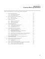
Part 1: Function Block
SECTION 1 Introduction to Function Blocks
SECTION 2 Function Block Specifications
SECTION 3 Creating Function Blocks
Part 2: Structured Text
SECTION 4 Introduction to Structured Text
SECTION 5 Structured Text (ST) Language Specifications
SECTION 6 Creating ST Programs
Appendices
TABLE OF CONTENTS
PRECAUTIONS . . . . . . . . . . . . . . . . . . . . . . . . . . . . . . . . . . . xxi
1
Intended Audience . . . . . . . . . . . . . . . . . . . . . . . . . . . . . . . . . . . . . . . . . . . . . . . . . . . . . . . . .
xxii
2
General Precautions . . . . . . . . . . . . . . . . . . . . . . . . . . . . . . . . . . . . . . . . . . . . . . . . . . . . . . . .
xxii
3
Safety Precautions . . . . . . . . . . . . . . . . . . . . . . . . . . . . . . . . . . . . . . . . . . . . . . . . . . . . . . . . .
xxii
4
Application Precautions. . . . . . . . . . . . . . . . . . . . . . . . . . . . . . . . . . . . . . . . . . . . . . . . . . . . .
xxiii
Part 1:
Function Blocks
SECTION 1
Introduction to Function Blocks . . . . . . . . . . . . . . . . . . . . . .
3
1-1
Introducing the Function Blocks . . . . . . . . . . . . . . . . . . . . . . . . . . . . . . . . . . . . . . . . . . . . . .
4
1-2
Function Blocks . . . . . . . . . . . . . . . . . . . . . . . . . . . . . . . . . . . . . . . . . . . . . . . . . . . . . . . . . . .
11
1-3
Variables . . . . . . . . . . . . . . . . . . . . . . . . . . . . . . . . . . . . . . . . . . . . . . . . . . . . . . . . . . . . . . . .
18
1-4
Converting Function Block Definitions to Library Files . . . . . . . . . . . . . . . . . . . . . . . . . . . .
23
1-5
Usage Procedures. . . . . . . . . . . . . . . . . . . . . . . . . . . . . . . . . . . . . . . . . . . . . . . . . . . . . . . . . .
23
1-6
Version Upgrade Information . . . . . . . . . . . . . . . . . . . . . . . . . . . . . . . . . . . . . . . . . . . . . . . .
25
SECTION 2
Function Block Specifications . . . . . . . . . . . . . . . . . . . . . . . .
31
2-1
Function Block Specifications . . . . . . . . . . . . . . . . . . . . . . . . . . . . . . . . . . . . . . . . . . . . . . . .
32
2-2
Data Types Supported in Function Blocks . . . . . . . . . . . . . . . . . . . . . . . . . . . . . . . . . . . . . .
43
2-3
Instance Specifications . . . . . . . . . . . . . . . . . . . . . . . . . . . . . . . . . . . . . . . . . . . . . . . . . . . . .
44
2-4
Programming Restrictions . . . . . . . . . . . . . . . . . . . . . . . . . . . . . . . . . . . . . . . . . . . . . . . . . . .
53
2-5
Function Block Applications Guidelines. . . . . . . . . . . . . . . . . . . . . . . . . . . . . . . . . . . . . . . .
58
2-6
Precautions for Instructions with Operands Specifying the First or Last of Multiple Words
67
2-7
Instruction Support and Operand Restrictions. . . . . . . . . . . . . . . . . . . . . . . . . . . . . . . . . . . .
70
2-8
CPU Unit Function Block Specifications . . . . . . . . . . . . . . . . . . . . . . . . . . . . . . . . . . . . . . .
71
2-9
Number of Function Block Program Steps and Instance Execution Time . . . . . . . . . . . . . .
78
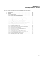
SECTION 3
Creating Function Blocks. . . . . . . . . . . . . . . . . . . . . . . . . . . .
81
3-1
Procedural Flow. . . . . . . . . . . . . . . . . . . . . . . . . . . . . . . . . . . . . . . . . . . . . . . . . . . . . . . . . . .
82
3-2
Procedures . . . . . . . . . . . . . . . . . . . . . . . . . . . . . . . . . . . . . . . . . . . . . . . . . . . . . . . . . . . . . . .
84
ix
TABLE OF CONTENTS
Part 2:
Structured Text (ST)
SECTION 4
Introduction to Structured Text . . . . . . . . . . . . . . . . . . . . . . 133
4-1
ST Language . . . . . . . . . . . . . . . . . . . . . . . . . . . . . . . . . . . . . . . . . . . . . . . . . . . . . . . . . . . . .
134
4-2
CX-Programmer Specifications. . . . . . . . . . . . . . . . . . . . . . . . . . . . . . . . . . . . . . . . . . . . . . .
135
SECTION 5
Structured Text (ST) Language Specifications . . . . . . . . . . 137
5-1
Structured Text Language Specifications . . . . . . . . . . . . . . . . . . . . . . . . . . . . . . . . . . . . . . .
138
5-2
Data Types Used in ST Programs . . . . . . . . . . . . . . . . . . . . . . . . . . . . . . . . . . . . . . . . . . . . .
139
5-3
Inputting ST Programs. . . . . . . . . . . . . . . . . . . . . . . . . . . . . . . . . . . . . . . . . . . . . . . . . . . . . .
140
5-4
ST Language Configuration . . . . . . . . . . . . . . . . . . . . . . . . . . . . . . . . . . . . . . . . . . . . . . . . .
144
5-5
Statement Descriptions . . . . . . . . . . . . . . . . . . . . . . . . . . . . . . . . . . . . . . . . . . . . . . . . . . . . .
155
5-6
ST-language Program Example . . . . . . . . . . . . . . . . . . . . . . . . . . . . . . . . . . . . . . . . . . . . . . .
173
5-7
Restrictions . . . . . . . . . . . . . . . . . . . . . . . . . . . . . . . . . . . . . . . . . . . . . . . . . . . . . . . . . . . . . .
174
SECTION 6
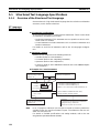
Creating ST Programs . . . . . . . . . . . . . . . . . . . . . . . . . . . . . . 177
6-1
Procedures . . . . . . . . . . . . . . . . . . . . . . . . . . . . . . . . . . . . . . . . . . . . . . . . . . . . . . . . . . . . . . .
178
Appendices
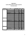
A
System-defined external variables supported in function blocks . . . . . . . . . . . . . . . . . . . . .
191
B
Structured Text Errors . . . . . . . . . . . . . . . . . . . . . . . . . . . . . . . . . . . . . . . . . . . . . . . . . . . . . .
193
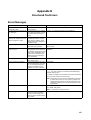
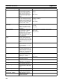
C
Function Descriptions . . . . . . . . . . . . . . . . . . . . . . . . . . . . . . . . . . . . . . . . . . . . . . . . . . . . . .
197
Index. . . . . . . . . . . . . . . . . . . . . . . . . . . . . . . . . . . . . . . . . . . . . 223
Revision History . . . . . . . . . . . . . . . . . . . . . . . . . . . . . . . . . . . 225
x
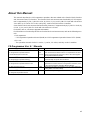
About this Manual:
This manual describes the CX-Programmer operations that are related to the function block functions
and Structured Text (ST) functions. The function block and structure text functionality of CX-Programmer is supported by CJ2H, CJ2M CPU Units, by CS1-H, CJ1-H, and CJ1M CPU Units with unit version
3.0 or later, by CP-series CPU Units, and by NSJ-series and FQM1-series Controllers.
Some function block and structure text functionality, however, is supported only by CJ2H CPU Units, by
CS1-H, CJ1-H, and CJ1M CPU Units with unit version 4.0 or later.
For details, refer to 1-6 Version Upgrade Information.
For information on functionality other than function blocks and structure text, refer to the following manuals.
• CX-Programmer
: CX-Programmer Operation Manual (W446) and CX-Programmer Operation Manual: SFC (W469)
• CPU Unit
: The operation manuals for the CS-series, CJ-series, CP-series, and NSJ-series Controllers
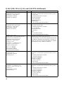
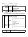
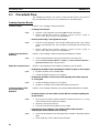
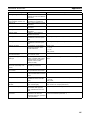
CX-Programmer Ver. 9.@ Manuals
Name
CXONE-AL@@C-V4/CXONE-AL@@D-V4
CX-Programmer Operation Manual
Function Blocks/Structured Text
Cat. No.
Contents
Explains how to use the CX-Programmer software’s function
W447
block and structured text functions. For explanations of other
(this
manual) shared CX-Programmer functions, refer to the CX-Programmer Operation Manual (W446).
CXONE-AL@@C-V4/CXONE-AL@@D-V4
CX-Programmer Operation Manual
W446
Provides information on how to use the CX-Programmer for
all functionality except for function blocks.
CXONE-AL@@C-V4/CXONE-AL@@D-V4
CX-Programmer Operation Manual: SFC
W469
CX-Net Operation Manual
W362
Explains how to use the SFC programming functions. For
explanations of other shared CX-Programmer functions, refer
to the CX-Programmer Operation Manual (W446).
Information on setting up networks, such as setting data links,
routing tables, and unit settings.
CXONE-AL@@C-V4/CXONE-AL@@D-V4
CX-Integrator Operation Manual
W464
Describes the operating procedures for the CX-Integrator.
xi
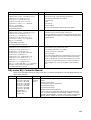
CJ2H, CJ2M, CS1-H, CJ1-H, and CJ1M CPU Unit Manuals
Name
SYSMAC CJ Series
CJ2H-CPU6@-EIP, CJ2H-CPU6@
CJ2M-CPU1@, CJ2M-CPU3@
Programmable Controllers
Hardware User's Manual
Cat. No.
Contents
W472
Provides an outline of and describes the design, installation,
maintenance, and other basic operations for the CJ-series
CJ2 CPU Units.
SYSMAC CJ Series
CJ2H-CPU6@-EIP, CJ2H-CPU6@
CJ2M-CPU1@, CJ2M-CPU3@
Programmable Controllers
Software User's Manual
W473
SYSMAC CS/CJ Series
CS1G/H-CPU@@ -EV1, CS1G/H-CPU@@H,
CS1D-CPU@@H, CS1D-CPU@@S,
CJ2H-CPU6@-EIP, CJ2H-CPU6@,
CJ2M-CPU1@, CJ2M-CPU3@
CJ1H-CPU@@H-R
CJ1G-CPU@@, CJ1G/H-CPU@@H,
CJ1G-CPU@@P, CJ1M-CPU@@
SYSMAC One NSJ Series
NSJ@-@@@@(B)-G5D
NSJ@-@@@@(B)-M3D
Programmable Controllers
Instructions Reference Manual
SYSMAC CS Series
CS1G/H-CPU@@H
Programmable Controllers
Operation Manual
W474
SYSMAC CJ Series
CJ1G-CPU@@, CJ1G/H-CPU@@H,
CJ1H-CPU@@H-R, CJ1G-CPU@@P,
CJ1M-CPU@@
Programmable Controllers
Operation Manual
The following information is included:
Overview and features
System configuration
Installation and wiring
Troubleshooting
Use this manual together with the W473.
Describes programming and other methods to use the functions of the CJ2 CPU Units.
The following information is included:
CPU Unit operation
Internal memory areas
Programming
Tasks
CPU Unit built-in functions
Use this manual together with the W472.
Describes the ladder diagram programming instructions supported by CS/CJ-series or NSJ-series PLCs.
When programming, use this manual together with the Operation Manual or Hardware User's Manual (CS1: W339, CJ1:
W393,or CJ2:W472) and Programming Manual or Software
User's Manual (CS1/CJ1:W394 or CJ2:W473).
W339
Provides an outline of and describes the design, installation,
maintenance, and other basic operations for the CS-series
PLCs.
The following information is included:
An overview and features
The system configuration
Installation and wiring
I/O memory allocation
Troubleshooting
W393
Use this manual together with the W394.
Provides an outline of and describes the design, installation,
maintenance, and other basic operations for the CJ-series
PLCs.
The following information is included:
An overview and features
The system configuration
Installation and wiring
I/O memory allocation
Troubleshooting
Use this manual together with the W394.
xii
Name
Cat. No.
SYSMAC CS/CJ Series
CS1G/H-CPU@@-EV1, CS1G/H-CPU@@H,
CS1D-CPU@@H, CS1D-CPU@@S,
CJ1G-CPU@@, CJ1G/H-CPU@@H,
CJ1H-CPU@@H-R, CJ1G-CPU@@P,
CJ1M-CPU@@, NSJ@-@@@@(B)-G5D,
NSJ@-@@@@(B)-M3D
Programmable Controllers
Programming Manual
SYSMAC CS/CJ Series
CS1G/H-CPU@@-EV1, CS1G/H-CPU@@H,
CS1D-CPU@@H, CS1D-CPU@@S,
CJ1G-CPU@@, CJ1G/H-CPU@@H,
CJ1H-CPU@@H-R, CJ1G-CPU@@P,
CJ1M-CPU@@, NSJ@-@@@@(B)-G5D,
NSJ@-@@@@(B)-M3D
Programmable Controllers
Instructions Reference Manual
CS1G/H-CPU@@-EV1, CS1G/H-CPU@@H
CS1D-CPU@@H, CS1D-CPU@@S,
CJ1H-CPU@@H-R, CJ1G-CPU@@,
CJ1M-CPU@@, CJ1G-CPU@@P,
CJ1G/H-CPU@@H, CJ2H-CPU6@-EIP,
CJ2H-CPU6@, CJ2M-CPU@@,
CS1W-SCU@@-V1, CS1W-SCB@@-V1,
CJ1W-SCU@@-V1, CP1H-X@@@@-@,
CP1H-XA@@@@-@, CP1H-Y@@@@-@,
CP1L-M/L@@@-@, CP1E-N@@D@-@
NSJ@-@@@@(B)-G5D, NSJ@-@@@@(B)-M3D
SYSMAC CS/CJ Series Communications
Commands Reference Manual
W394
Contents
Describes programming and other methods to use the functions of the CS/CJ-series and NSJ-series PLCs.
The following information is included:
Programming
Tasks
File memory
Other functions
Use this manual together with the W339 or W393.
W340
Describes the ladder diagram programming instructions supported by CS/CJ-series and NSJ-series PLCs.
When programming, use this manual together with the Operation Manual (CS1: W339 or CJ1: W393) and Programming
Manual (W394).
W342
Describes the communications commands that can be
addressed to CS/CJ-series CPU Units.
The following information is included:
C-series (Host Link) commands
FINS commands
Note: This manual describes commands that can be sent to
the CPU Unit without regard for the communications path,
which can be through a serial communications port on the
CPU Unit, a communications port on a Serial Communications Unit/Board, or a port on any other Communications
Unit.
NSJ-series NSJ Controller Manual
Refer to the following manual for NSJ-series NSJ Controller specifications and handling methods not
given in this manual.
Cat. No.
W452
Models
NSJ5-TQ@@(B)-G5D
NSJ5-SQ@@(B)-G5D
NSJ8-TV@@(B)-G5D
NSJ10-TV@@(B)-G5D
NSJ12-TS@@(B)-G5D
NSJ5-TQ@@(B)-M3D
NSJ5-SQ@@(B)-M3D
NSJ8-TV@@(B)-M3D
NSJW-ETN21
NSJW-CLK21-V1
NSJW-IC101
Name
NSJ Series
Operation
Manual
Description
Provides the following information about the NSJ-series NSJ Controllers:
Overview and features
Designing the system configuration
Installation and wiring
I/O memory allocations
Troubleshooting and maintenance
Use this manual in combination with the following manuals: SYSMAC CS Series Operation Manual (W339), SYSMAC CJ Series
Operation Manual (W393), SYSMAC CS/CJ Series Programming
Manual (W394), and NS-V1/-V2 Series Setup Manual (V083)
xiii
FQM1 Series Manuals (Unit Version 3.0 or Later)
Refer to the following manuals for specifications and handling methods not given in this manual for
FQM1 Series unit version 3.0 (FQM1-CM002/MMP22/MMA22).
Cat. No.
O012
Models
FQM1-CM002
FQM1-MMP22
FQM1-MMA22
Name
FQM1 Series
Operation Manual
O013
FQM1-CM002
FQM1-MMP22
FQM1-MMA22
FQM1 Series
Instructions
Reference Manual
Description
Provides the following information about the FQM1-series Modules
(unit version 3.0):
Overview and features
Designing the system configuration
Installation and wiring
I/O memory allocations
Troubleshooting and maintenance
Individually describes the instructions used to program the FQM1.
Use this manual in combination with the FQM1 Series
Operation Manual (O012) when programming.
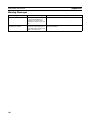
CP-series PLC Unit Manuals
Refer to the following manuals for specifications and handling methods not given in this manual for CPseries CPU Units.
Cat. No.
Models
Name
W450
CP1H-X@@@@-@ SYSMAC CP Series
CP1H-XA@@@@-@ CP1H CPU Unit
CP1H-Y@@@@-@ Operation Manual
W462
W451
Description
Provides the following information on the CP-series CP1H PLCs:
• Overview/Features
• System configuration
• Mounting and wiring
• I/O memory allocation
• Troubleshooting
Use this manual together with the CP1H/CP1L Programmable
Controllers Programming Manual (W451).
CP1L-M@@@@-@ SYSMAC CP Series Provides the following information on the CP-series CP1L PLCs:
CP1L-L@@@@-@
CP1L CPU Unit Oper- • Overview/Features
ation Manual
• System configuration
• Mounting and wiring
• I/O memory allocation
• Troubleshooting
Use this manual together with the CP1H Programmable Controllers Programming Manual (W451).
CP1H-X@@@@-@ SYSMAC CP Series Provides the following information on the CP-series CP1H and
CP1H-XA@@@@-@ CP1H/CP1L CPU
CP1L PLCs:
CP1H-Y@@@@-@ Unit Programming
• Programming instructions
CP1L-M@@@@-@ Manual
• Programming methods
CP1L-L@@@@-@
• Tasks
Use this manual together with the CP1H/CP1L Programmable
Controllers Operation Manual (W450).
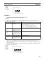
Installation from CX-One
For details on procedures for installing the CX-Programmer from CX-One FA Integrated Tool Package,
refer to the CX-One Ver. 3.0 Setup Manual provided with CX-One.
Cat. No.
W463
xiv
Model
CXONE-AL@@C-V4/
AL@@D-V4/CXONELT@@C-V4
Manual name
CX-One Setup Manual
Contents
Installation and overview of CX-One FA
Integrated Tool Package.
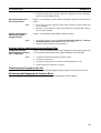
Overview of Contents
Precautions provides general precautions for using the CX-Programmer.
Part 1
Part 1 contains the following sections.
Section 1 introduces the function block functionality of the CX-Programmer and explains the features
that are not contained in the non-function block version of CX-Programmer.
Section 2 provides specifications for reference when using function blocks, including specifications on
function blocks, instances, and compatible PLCs, as well as usage precautions and guidelines.
Section 3 describes the procedures for creating function blocks on the CX-Programmer.
Part 2
Part 2 contains the following sections.
Section 4 introduces the structure text programming functionality of the CX-Programmer and explains
the features that are not contained in the non-structured text version of CX-Programmer.
Section 5 provides specifications for reference when using structured text programming, as well as
programming examples and restrictions.
Section 6 explains how to create ST programs.
Appendices provide information on structured text errors and ST function descriptions.
!WARNING Failure to read and understand the information provided in this manual may result in personal injury or death, damage to the product, or product failure. Please read each section
in its entirety and be sure you understand the information provided in the section and
related sections before attempting any of the procedures or operations given.
xv
xvi
Read and Understand this Manual
Please read and understand this manual before using the product. Please consult your OMRON
representative if you have any questions or comments.
Warranty and Limitations of Liability
WARRANTY
(1) The warranty period for the Software is one year from either the date of purchase or the date on which
the Software is delivered to the specified location.
(2) If the User discovers a defect in the Software (i.e., substantial non-conformity with the manual), and
returns it to OMRON within the above warranty period, OMRON will replace the Software without charge
by offering media or downloading services from the Internet. And if the User discovers a defect in the
media which is attributable to OMRON and returns the Software to OMRON within the above warranty
period, OMRON will replace the defective media without charge. If OMRON is unable to replace the
defective media or correct the Software, the liability of OMRON and the User's remedy shall be limited to
a refund of the license fee paid to OMRON for the Software.
LIMITATIONS OF LIABILITY
(1) THE ABOVE WARRANTY SHALL CONSTITUTE THE USER'S SOLE AND EXCLUSIVE REMEDIES
AGAINST OMRON AND THERE ARE NO OTHER WARRANTIES, EXPRESSED OR IMPLIED,
INCLUDING BUT NOT LIMITED TO, WARRANTY OF MERCHANTABILITY OR FITNESS FOR A
PARTICULAR PURPOSE. IN NO EVENT WILL OMRON BE LIABLE FOR ANY LOST PROFITS OR
OTHER INDIRECT, INCIDENTAL, SPECIAL, OR CONSEQUENTIAL DAMAGES ARISING OUT OF
USE OF THE SOFTWARE.
(2) OMRON SHALL ASSUME NO LIABILITY FOR DEFECTS IN THE SOFTWARE BASED ON
MODIFICATION OR ALTERATION OF THE SOFTWARE BY THE USER OR ANY THIRD PARTY.
(3) OMRON SHALL ASSUME NO LIABILITY FOR SOFTWARE DEVELOPED BY THE USER OR ANY
THIRD PARTY BASED ON THE SOFTWARE OR ANY CONSEQUENCE THEREOF.
xvii
Application Considerations
SUITABILITY FOR USE
THE USER SHALL NOT USE THE SOFTWARE FOR A PURPOSE THAT IS NOT DESCRIBED IN THE
ATTACHED USER MANUAL.
xviii
Disclaimers
CHANGE IN SPECIFICATIONS
The software specifications and accessories may be changed at any time based on improvements or for
other reasons.
EXTENT OF SERVICE
The license fee of the Software does not include service costs, such as dispatching technical staff.
ERRORS AND OMISSIONS
The information in this manual has been carefully checked and is believed to be accurate; however, no
responsibility is assumed for clerical, typographical, or proofreading errors, or omissions.
xix
xx
PRECAUTIONS
This section provides general precautions for using the CX-Programmer and the Programmable Logic Controller.
The information contained in this section is important for the safe and reliable application of the CX-Programmer
and Programmable Controller. You must read this section and understand the information contained before
attempting to set up or operate the CX-Programmer and Programmable Controller.
1
2
3
4
Intended Audience . . . . . . . . . . . . . . . . . . . . . . . . . . . . . . . . . . . . . . . . . . . . .
General Precautions . . . . . . . . . . . . . . . . . . . . . . . . . . . . . . . . . . . . . . . . . . . .
Safety Precautions. . . . . . . . . . . . . . . . . . . . . . . . . . . . . . . . . . . . . . . . . . . . . .
Application Precautions . . . . . . . . . . . . . . . . . . . . . . . . . . . . . . . . . . . . . . . . .
xxii
xxii
xxii
xxiii
xxi
1
Intended Audience
1
Intended Audience
This manual is intended for the following personnel, who must also have
knowledge of electrical systems (an electrical engineer or the equivalent).
• Personnel in charge of installing FA systems.
• Personnel in charge of designing FA systems.
• Personnel in charge of managing FA systems and facilities.
2
General Precautions
The user must operate the product according to the performance specifications described in the operation manuals.
Before using the product under conditions which are not described in the
manual or applying the product to nuclear control systems, railroad systems,
aviation systems, vehicles, combustion systems, medical equipment, amusement machines, safety equipment, and other systems, machines, and equipment that may have a serious influence on lives and property if used
improperly, consult your OMRON representative.
Make sure that the ratings and performance characteristics of the product are
sufficient for the systems, machines, and equipment, and be sure to provide
the systems, machines, and equipment with double safety mechanisms.
This manual provides information for programming and operating the product.
Be sure to read this manual before attempting to use the product and keep
this manual close at hand for reference during operation.
!WARNING It is extremely important that a PLC and all PLC Units be used for the specified purpose and under the specified conditions, especially in applications that
can directly or indirectly affect human life. You must consult with your OMRON
representative before applying a PLC System to the above-mentioned applications.
3
Safety Precautions
!WARNING Confirm safety sufficiently before transferring I/O memory area status from the
CX-Programmer to the actual CPU Unit. The devices connected to Output
Units may malfunction, regardless of the operating mode of the CPU Unit.
Caution is required in respect to the following functions.
• Transferring from the CX-Programmer to real I/O (CIO Area) in the CPU
Unit using the PLC Memory Window.
• Transferring from file memory to real I/O (CIO Area) in the CPU Unit using
the Memory Card Window.
!Caution Variables must be specified either with AT settings (or external variables), or
the variables must be the same size as the data size to be processed by the
instruction when specifying the first or last address of multiple words in the
instruction operand.
1. If a non-array variable with a different data size and without an AT setting
is specified, the CX-Programmer will output an error when compiling.
2. Array Variable Specifications
xxii
4
Application Precautions
• When the size to be processed by the instruction operand is fixed:
The number of array elements must be the same as the number of elements to be processed by the instruction. Otherwise, the CX-Programmer
will output an error when compiling.
• When the size to be processed by the instruction operand is not fixed:
The number of array elements must be greater than or the same as the
size specified in the other operands.
• If the other operand specifying a size is a constant, the CX-Programmer will output an error when compiling.
• If the other operand specifying a size is a variable, the CX-Programmer
will not output an error when compiling, even if the size of the array
variable is not the same as that specified by the other operand (variable). A warning message, however, will be displayed. In particular, if
the number of array elements is less than the size specified by the other operand (e.g., the size of the instruction operand is 16, and the number of elements registered in the actual variable table is 10), the
instruction will execute read/write processing for the area that exceeds
the number of elements. For example, read/write processing will be executed for the 6 words following those for the number of elements registered in the actual variable table. If these words are used for other
instructions (including internal variable allocations), unexpected operation will occur, which may result in serious accidents.
Check that the system will not be adversely affected if the size of the
variable specified in the operand is less than the size in the operand
definition before starting PLC operations.
!Caution Confirm safety at the destination node before transferring a program to
another node or changing contents of the I/O memory area. Doing either of
these without confirming safety may result in injury.
!Caution Execute online editing only after confirming that no adverse effects will be
caused by extending the cycle time. Otherwise, the input signals may not be
readable.
!Caution If synchronous unit operation is being used, perform online editing only after
confirming that an increased synchronous processing time will not affect the
operation of the main and slave axes.
!Caution Confirm safety sufficiently before monitoring power flow and present value
status in the Ladder Section Window or when monitoring present values in the
Watch Window. If force-set/reset or set/reset operations are inadvertently performed by pressing short-cut keys, the devices connected to Output Units
may malfunction, regardless of the operating mode of the CPU Unit.
4
Application Precautions
Observe the following precautions when using the CX-Programmer.
• User programs cannot be uploaded to the CX-Programmer.
• Observe the following precautions before starting the CX-Programmer.
• Exit all applications not directly related to the CX-Programmer. Particularly exit any software such as screen savers, virus checkers, E-mail
or other communications software, and schedulers or other applications that start up periodically or automatically.
xxiii
4
Application Precautions
• Disable sharing hard disks, printers, or other devices with other computers on any network.
• With some notebook computers, the RS-232C port is allocated to a
modem or an infrared line by default. Following the instructions in documentation for your computer and enable using the RS-232C port as
a normal serial port.
• With some notebook computers, the default settings for saving energy
do not supply the rated power to the RS-232C, USB and Ethernet port.
There may be both Windows settings for saving energy, as well as setting for specific computer utilities and the BIOS. Following the instructions in documentation for your computer, disable all energy saving
settings.
• Do not turn OFF the power supply to the PLC or disconnect the connecting cable while the CX-Programmer is online with the PLC. The computer
may malfunction.
• Confirm that no adverse effects will occur in the system before attempting
any of the following. Not doing so may result in an unexpected operation.
• Changing the operating mode of the PLC.
• Force-setting/force-resetting any bit in memory.
• Changing the present value of any word or any set value in memory.
• Check the user program for proper execution before actually running it on
the Unit. Not checking the program may result in an unexpected operation.
• When online editing is performed, the user program and parameter area
data in CJ2, CS1-H, CJ1-H, CJ1M, and CP1H CPU Units is backed up in
the built-in flash memory. The BKUP indicator will light on the front of the
CPU Unit when the backup operation is in progress. Do not turn OFF the
power supply to the CPU Unit when the BKUP indicator is lit. The data will
not be backed up if power is turned OFF. To display the status of writing to
flash memory on the CX-Programmer, select Display dialog to show PLC
Memory Backup Status in the PLC properties and then select Windows PLC Memory Backup Status from the View Menu.
• Programs including function blocks (ladder programming language or
structured text (ST) language) can be downloaded or uploaded in the
same way as standard programs that do not contain function blocks.
Tasks including function blocks, however, cannot be downloaded in task
units (uploading is possible).
• If a user program containing function blocks created on the CX-Programmer Ver. 5.0 or later is downloaded to a CPU Unit that does not support
function blocks (CS/CJ-series CPU Units with unit version 2.0 or earlier),
all instances will be treated as illegal commands and it will not be possible
to edit or execute the user program.
• If the input variable data is not in boolean format, and numerical values
only (e.g., 20) are input in the parameters, the actual value in the CIO
Area address (e.g., 0020) will be passed. Therefore, be sure to include an
&, #, or +, - prefix before inputting the numerical value.
• Addresses can be set in input parameters, but an address itself cannot be
passed as an input variable. (Even if an address is set as an input parameter, the value passed to the function block will be that for the size of data
of the input variable.) Therefore, an input variable cannot be used as the
operand of an instruction in the function block when the operand specifies
the first or last of multiple words. With CX-Programmer version 7.0, use
xxiv
4
Application Precautions
an input-output variable specified as an array variable (with the first
address set for the input parameter) and specify the first or last element of
the array variable, or, with any version of CX-Programmer, use an internal
variable with an AT setting. Alternatively, specify the first or last element in
an internal variable specified as an array variable.
• Values are passed in a batch from the input parameters to the input variables or input-output variables before algorithm execution (not at the
same time as the instructions in the algorithm are executed). Therefore, to
pass the value from a parameter to an input variable or input-output variable when an instruction in the function block algorithm is executed, use
an internal variable or external variable instead of an input variable or
input-output variable. The same applies to the timing for writing values to
the parameters from output variables.
• Always use internal variables with AT settings in the following cases.
• The addresses allocated to Basic I/O Units, Special I/O Units, and
CPU Bus Units cannot be registered to global symbols, and these variables cannot be specified as external variables (e.g., the data set for
global variables may not be stable).
• Use internal variables when Auxiliary Area bits other than those preregistered to external variables are registered to global symbols and
these variables are not specified as external variables.
• Use internal variables when specifying PLC addresses for another
node on the network: For example, the first destination word at the remote node for SEND(090) and the first source word at the remote node
for RECV(098).
• Use internal variables when the first or last of multiple words is specified by an instruction operand and the operand cannot be specified as
an array variable (e.g., the number of array elements cannot be specified).
xxv
Application Precautions
xxvi
4
Part 1:
Function Blocks
SECTION 1
Introduction to Function Blocks
This section introduces the function block functionality of the CX-Programmer and explains the features that are not
contained in the non-function block version of CX-Programmer.
1-1
1-2
Introducing the Function Blocks. . . . . . . . . . . . . . . . . . . . . . . . . . . . . . . . . . .
4
1-1-1
Overview and Features . . . . . . . . . . . . . . . . . . . . . . . . . . . . . . . . . . .
4
1-1-2
Function Block Specifications . . . . . . . . . . . . . . . . . . . . . . . . . . . . .
5
1-1-3
Files Created with CX-Programmer Ver. 6.0 or Later . . . . . . . . . . .
8
1-1-4
Function Block Menus in CX-Programmer Ver. 5.0
(and later Versions) . . . . . . . . . . . . . . . . . . . . . . . . . . . . . . . . . . . . . .
8
Function Blocks . . . . . . . . . . . . . . . . . . . . . . . . . . . . . . . . . . . . . . . . . . . . . . .
11
1-2-1
11
Outline . . . . . . . . . . . . . . . . . . . . . . . . . . . . . . . . . . . . . . . . . . . . . . .
1-2-2
Advantages of Function Blocks . . . . . . . . . . . . . . . . . . . . . . . . . . . .
12
1-2-3
Function Block Structure . . . . . . . . . . . . . . . . . . . . . . . . . . . . . . . . .
13
Variables . . . . . . . . . . . . . . . . . . . . . . . . . . . . . . . . . . . . . . . . . . . . . . . . . . . . .
18
1-3-1
Introduction. . . . . . . . . . . . . . . . . . . . . . . . . . . . . . . . . . . . . . . . . . . .
18
1-3-2
Variable Usage and Properties . . . . . . . . . . . . . . . . . . . . . . . . . . . . .
19
1-3-3
Variable Properties . . . . . . . . . . . . . . . . . . . . . . . . . . . . . . . . . . . . . .
19
1-3-4
Variable Properties and Variable Usage . . . . . . . . . . . . . . . . . . . . . .
20
1-3-5
Internal Allocation of Variable Addresses . . . . . . . . . . . . . . . . . . . .
21
1-4
Converting Function Block Definitions to Library Files . . . . . . . . . . . . . . . .
23
1-5
Usage Procedures . . . . . . . . . . . . . . . . . . . . . . . . . . . . . . . . . . . . . . . . . . . . . .
23
1-5-1
Creating Function Blocks and Executing Instances . . . . . . . . . . . . .
23
1-5-2
Reusing Function Blocks . . . . . . . . . . . . . . . . . . . . . . . . . . . . . . . . .
24
Version Upgrade Information . . . . . . . . . . . . . . . . . . . . . . . . . . . . . . . . . . . . .
25
1-3
1-6
3
Section 1-1
Introducing the Function Blocks
1-1
1-1-1
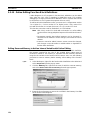
Introducing the Function Blocks
Overview and Features
The CX-Programmer Ver. 5.0 (and later versions) is a Programming Device
that can use standard IEC 61131-3 function blocks. The CX-Programmer
function block function is supported for CJ2 CPU Units, CP1H CPU Units,
NSJ-series NSJ Controllers, and FQM1 Flexible Motion Controllers as well as
CS/CJ-series CPU Units with unit version 3.0 or later and has the following
features.
• User-defined processes can be converted to block format by using function blocks.
• Function block algorithms can be written in the ladder programming language or in the structured text (ST) language. (See note.)
• When ladder programming is used, ladder programs created with nonCX-Programmer Ver. 4.0 or earlier can be reused by copying and pasting.
• When ST language is used, it is easy to program mathematical processes that would be difficult to enter with ladder programming.
Note
The ST language is an advanced language for industrial control
(primarily Programmable Logic Controllers) that is described in IEC
61131-3. The ST language supported by CX-Programmer conforms to the IEC 61131-3 standard.
• Function blocks can be created easily because variables do not have to
be declared in text. They are registered in variable tables.
A variable can be registered automatically when it is entered in a ladder or
ST program. Registered variables can also be entered in ladder programs
after they have been registered in the variable table.
• A single function block can be converted to a library function as a single
file, making it easy to reuse function blocks for standard processing.
• A program check can be performed on a single function block to easily
confirm the function block’s reliability as a library function.
• Programs containing function blocks (ladder programming language or
structured text (ST) language) can be downloaded or uploaded in the
same way as standard programs that do not contain function blocks.
Tasks containing function blocks, however, cannot be downloaded in task
units (uploading is possible).
• One-dimensional array variables are supported, so data handling is easier for many applications.
Note
The IEC 61131 standard was defined by the International Electrotechnical Commission (IEC) as an international programmable logic controller (PLC) standard. The standard is divided into 7 parts.
Specifications related to PLC programming are defined in Part 3
Textual Languages (IEC 61131-3).
• A function block (ladder programming language or structured text (ST)
language) can be called from another function block (ladder programming
language or structured text (ST) language). Function blocks can be
nested up to 8 levels and ladder/ST language function blocks can be combined freely.
4
Section 1-1
Introducing the Function Blocks
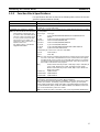
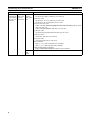
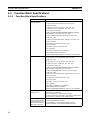
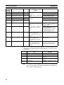
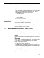
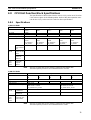
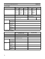
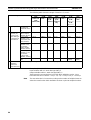
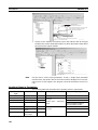
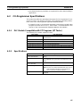
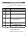
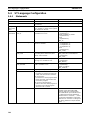
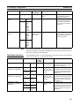
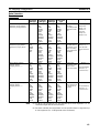
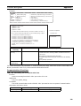
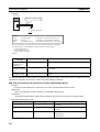
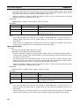
1-1-2
Function Block Specifications
For specifications that are not listed in the following table, refer to the CX-Programmer Operation Manual (W446).
Item
Specifications
CXONE-AL@@C-V4/AL@@D-V4
CXONE-AL@@C-V4: CD-ROM
CXONE-AL@@D-V4: DVD-ROM
CS/CJ-series CS1-H, CJ1-H, and CJ1M CPU Units with unit version 3.0 or later
Compatible CPU Units (PLC models)
Note The function block and structured are compatible.
Device Type
CPU Type
text functions supported by CS/
CJ-series CPU Units with unit ver- • CJ2H
CJ2H-CPU68/67/66/65/64/68-EIP/67-EIP/66-EIP/65-EIP
sion 4.0 or later can not be used
/64-EIP
in CS/CJ-series CPU Units with
• CJ2M
CJ2M-CPU11/12/13/14/15/31/32/33/34/35
unit version 3.0 or earlier, CPCS1G-CPU42H/43H/44H/45H
series PLCs, NSJ-series PLCs, or • CS1G-H
•
CS1H-H
CS1H-CPU63H/64H/65H/66H/67H
FQM1-series PLCs.
• CJ1G-H
CJ1G-CPU42H/43H/44H/45H
For details, refer to 1-6 Version
Upgrade Information.
• CJ1H-H
CJ1H-CPU65H/66H/67H/64H-R/65H-R/66H-R/67H-R
• CJ1M
CJ1M-CPU11/12/13/21/22/23
The following CP-series CPU Units are compatible.
• CP1H
CP1H-X/XA/Y
• CP1L
CP1L-M/L
Model number
Setup disk
Note If a user program containing function blocks created on the CX-Programmer Ver. 5.0 or later is downloaded to a CPU Unit that does not support
function blocks (CS/CJ-series CPU Units with unit version 2.0 or earlier),
all instances will be treated as illegal commands and it will not be possible to edit or execute the user program.
• NSJ
G5D (Used for the NSJ5-TQ0@-G5D, NSJ5-SQ0@-G5D, NSJ8
-TV0@-G5D, NSJ10-TV0@-G5D, and NSJ12-TS0@-G5D)
M3D (Used for the NSJ5-TQ0@-M3D, NSJ5-SQ0@-M3D, and
NSJ8-TV0@-M3D)
• FQM1-CM
FQM1-CM002
• FQM1-MMA FQM1-MMA22
• FQM1-MMP FQM1-MMP22
CS/CJ/CP Series Function Restrictions
• Instructions Not Supported in Function Block Definitions
Block Program Instructions (BPRG and BEND), Subroutine Instructions (SBS,
GSBS, RET, MCRO, and SBN), Jump Instructions (JMP, CJP, and CJPN),
Step Ladder Instructions (STEP and SNXT), Immediate Refresh Instructions
(!), I/O REFRESH (IORF), ONE-MS TIMER (TMHH and TMHHX) (These timers can be used with CJ1-H-R CPU Units.)
Note For details and other restrictions, refer to 2-4 Programming Restrictions.
5
Introducing the Function Blocks
Functions not
supported by
CX-Programmer Ver. 4.0
or earlier.
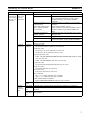
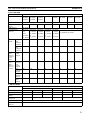
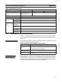
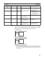
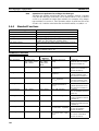
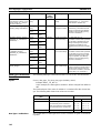
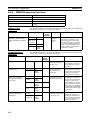
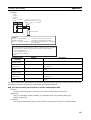
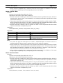
6
Item
Defining
and creating function blocks
Section 1-1
Specifications
Number of
CJ2H Units:
function
• CJ2H-CPU6@(-EIP): 2,048 max. per CPU Unit
block definiCJ2M CPU Units:
tions
• CJ2M-CPU@1/@2/@3: 256 max. per CPU Unit
• CJ2M-CPU@4/@5: 2,048 max. per CPU Unit
CS1-H/CJ1-H CPU Units:
• Suffix -CPU44H/45H/64H/65H/66H/67H/64H-R/65H-R/66H-R/67H-R: 1,024
max. per CPU Unit
• Suffix -CPU42H/43H/63H: 128 max. per CPU Unit
CJ1M CPU Units:
• CJ1M-CPU11/12/13/21/22/23: 128 max. per CPU Unit
CP1H CPU Units:
• All models: 128 max. per CPU Unit
CP1L CPU Units:
• CP1L-M/L: 128 max. per CPU Unit
NSJ Controllers:
• NSJ@-@@@@-G5D: 1,024 max. per Controller;
NSJ@-@@@@-M3D: 128 max. per Controller
FQM1 Flexible Motion Controllers:
• FQM1-CM002/MMA22/MMP22: 128 max. per Controller
Function
64 characters max.
block
names
Section 1-1
Introducing the Function Blocks
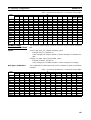
Functions not
supported by
CX-Programmer Ver. 4.0
or earlier.
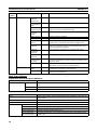
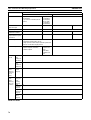
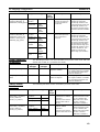
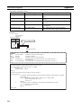
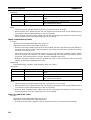
Item
Defining
Variables
and creating function blocks
Variable names
Variable types
Specifications
30,000 characters max.
Input variables (Inputs), output variables (Outputs), input-output variables (In Out), internal
variables (Internals), and external variables
(Externals)
Number of variables used in
a function block
(not including internal variables, external variables,
EN, and EN0)
Language
Creating
instances
Number of
instances
Maximum number of variables per function block
definition
• Input-output variables: 16 max.
• Input variables + input-output variables: 64 max.
• Output variables + input-output variables: 64
max.
Allocation of addresses
Automatic allocation (The allocation range can be
used by variables
set by the user.)
Actual address specification Supported
Array specifications
Supported (one-dimensional arrays only and only
for internal variables and input-output variables)
Function blocks can be created in ladder programming language or structured
text (ST, see note).
CJ2H CPU Units:
• CJ2H-CPU6@(-EIP): 2,048 max. per CPU Unit
CJ2M CPU Units:
• CJ2M-CPU@1/@2/@3: 256 max. per CPU Unit
• CJ2M-CPU@4/@5: 2,048 max. per CPU Unit
CS1-H/CJ1-H CPU Units:
• Suffix -CPU44H/45H/64H/65H/66H/67H/64H-R/65H-R/66H-R/67H-R: 2,048
max. per CPU Unit
• Suffix -CPU42H/43H/63H: 256 max. per CPU Unit
CJ1M CPU Units:
• CJ1M-CPU11/12/13/21/22/23: 256 max. per CPU Unit
Storing
function
blocks as
files
Instance
names
Project files
Program
files
Function
block library
files
CP1H CPU Units:
• All models: 256 max. per CPU Unit
CP1L CPU Units:
• CP1L-M/L: 256 max. per CPU Unit
NSJ Controllers:
• SJ@-@@@@-G5D: 2,048 max. per Controller;
NSJ@-@@@@-M3D: 256 max. per Controller
FQM1 Flexible Motion Controllers:
• FQM1-CM002/MMA22/MMP22: 256 max. per Controller
15,000 characters max.
The project file (.cxp/cxt) Includes function block definitions and instances.
The file memory program file (*.obj) includes function block definitions and
instances.
Each function block definition can be stored as a single file (.cxf) for reuse in
other projects.
7
Section 1-1
Introducing the Function Blocks
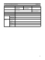
Note
1-1-3
The structured text (ST language) conforms to the IEC 61131-3 standard, but
CX-Programmer Ver. 5.0 supports only assignment statements, selection
statements (CASE and IF statements), iteration statements (FOR, WHILE,
REPEAT, and EXIT statements), RETURN statements, arithmetic operators,
logical operators, comparison functions, numeric functions, standard string
functions, numeric string functions, OMRON expansion functions, and comments. For details, refer to SECTION 5 Structured Text (ST) Language Specifications in Part 2: Structured Text (ST).
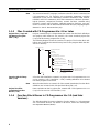
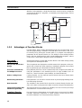
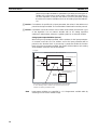
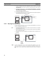
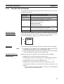
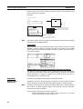
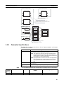
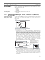
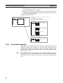
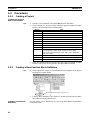
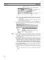
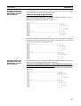
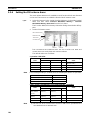
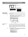
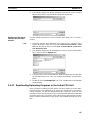
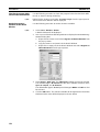
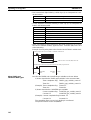
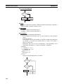
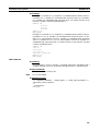
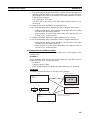
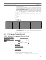
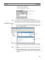
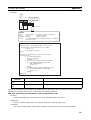
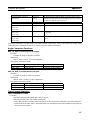
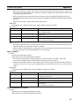
Files Created with CX-Programmer Ver. 6.0 or Later
Project Files (*.cxp) and
File Memory Program
Files (*.obj)
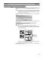
Projects created using CX-Programmer that contain function block definitions
and projects with instances are saved in the same standard project files
(*.cxp) and file memory program files (*.obj).
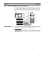
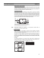
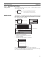
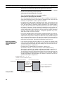
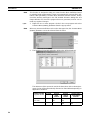
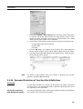
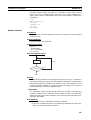
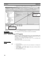
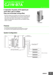
The following diagram shows the contents of a project. The function block definitions are created at the same directory level as the program within the relevant PLC directory.
Project file (.cxp)
PLC1
Global symbol table
I/O table
PLC Setup
PLC memory table
Program (with rung comments)
Local symbol table
Section 1 (with instances)
Section 2 (with instances)
END section (with instances)
Function block definitions
FunctionBlock1
FunctionBlock2
PLC2
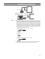
Function Block Library
Files (*.cxf)
Note
Project Text Files
Containing Function
Blocks (*.cxt)
1-1-4
Instances created
in program
sections.
Each function block can be
stored in a separate
definition file (.cxf).
A function block definition created in a project with CX-Programmer Ver. 6.0
can be saved as a file (1 definition = 1 file), enabling definitions to be loaded
into other programs and reused.
When function blocks are nested, all of the nested (destination) function block
definitions are included in this function block library file (.cxf).
Data equivalent to that in project files created with CX-Programmer Ver. 6.0
(*.cxp) can be saved as CXT text files (*.cxt).
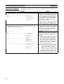
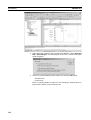
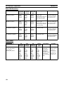
Function Block Menus in CX-Programmer Ver. 5.0 (and later
Versions)
The following tables list menus related to function blocks in CX-Programmer
Ver. 5.0 and later versions. For details on all menus, refer to the CX-Programmer Operation Manual (W446).
8
Section 1-1
Introducing the Function Blocks
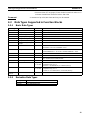
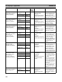
Main Menu
Main
menu
File
Edit
View
Submenu
Function Block
Load Function --Block from File
Save Function --Block to File
Update Function Block
---
To Lower Layer
---
Function Block (ladder) generation
---
Monitor FB Instance
---
To Lower Layer
---
To Upper Layer
---
Window
Insert
PLC
Program
Shortcut
FB Instance
Viewer
---
Function Block Invocation
F
Function Block Parameter
P
Memory Function
Block/
AllocaSFC
tion
Memory
Function Block
/SFC Memory
Allocation
Function Block
/SFC Memory
Statistics
Function Block
Instance
Address
Optimize Function Block/SFC
Memory
Begin
Send Change
---
Cancel
---
Transfer FB
Source
Release FB
Online Edit
Access Rights
---
Online Edit
Function
Reads the saved function block library files (*.cxf).
Saves the created function block definitions to a file ([function block library file]*.cxf).
When a function block definition’s input variables, output
variables, or input-output variables have been changed
after the instance was created, an error will be indicated by
displaying the instance’s left bus bar in red. This command
updates the instance with the new information and clears
the error.
Jumps to the function block definition for the selected
instance.
Generates a ladder-programmed function block for the
selected program section while automatically determining
address application conditions.
When monitoring the program online, monitors ST variable
status as well as I/O bit and word status (I/O bit monitor) of
the ladder diagram in the instance.
(Supported by CX-Programmer Ver. 6.1 and later only).
Displays on the right side the contents of the function block
definition of the selected instance. (Supported by CX-Programmer Ver. 6.0 and later only.)
Returns to the calling instance (ladder diagram or ST).
(Supported by CX-Programmer Ver. 6.0 and later only.)
Displays the FB Instance Viewer. (When nesting, the display shows details such as the relationship between
instance nesting levels and allocated variable addresses in
the instances.)
Creates an instance in the program (section) at the present
cursor location.
When the cursor is located to the left of an input variable or
the right of an output variable, sets the variable’s input or
output parameter.
Sets the range of addresses (function block instance areas)
internally allocated to the selected instance’s variables.
---
Checks the status of the addresses internally allocated to
the selected instance’s variables.
---
Checks the addresses internally allocated to each variable
in the selected instance.
---
Optimizes the allocation of addresses internally allocated to
variables.
-----
Starts online editing of a function block.
Transfers changes made during online editing of a function
block.
Cancels changes made to a function block being edited
online.
Transfers only the function block source.
---
Forcefully releases the access rights for function block,
SFC, and ST online editing held by another user.
9
Section 1-1
Introducing the Function Blocks
Main
menu
Tools
Submenu
Simulation
Shortcut
Break Point |
Set/Clear
Break Point
Break Point |
Clear All Break
Point
Mode | Run
(Monitor Mode)
Mode | Stop
(Program
Mode)
Mode | Pause
Step Run
Step Run |
Step In
Step Run |
Step Out
Step Run |
Continuous
Step Run
Step Run |
Scan Run
Always Display
Current Execution Point
Break Point List
Change Input mode Smart Input
Mode
Classic Mode
Function
---
Sets or clears a break point.
---
Clears all break points.
---
Executes continuous scanning. (Sets the ladder execution
engine’s run mode to MONITOR mode.)
Sets the simulator’s operation mode to PROGRAM mode.
---
-------
---
Pauses simulator operation.
Executes just one step of the simulator’s program.
When there is a function block call instruction, this command moves to execution of the internal program step.
When a function block’s internal program step is being executed, this command returns to the next higher level (call
source) and pauses execution.
Executes steps continuously for a fixed length of time.
---
Executes for one cycle and pauses execution.
---
Used with the Step Run or Continuous Step Run commands to automatically scroll the display and always show
the pause point.
Displays a list of the break points that have been set.
(Operation can be jumped to a specified point.)
The Smart Input Mode can be used to automatically display
candidates for instructions and addresses.
The Classic Mode is the input mode that is used previous
version of CX-Programmer.
---
-------
Main Pop-up Menus
Pop-up Menu for Function Block Definitions
Pop-up menu
Insert Function Block
Ladder
Structured Text
From file
Function
Creates a function block definition with a ladder programming language algorithm.
Creates a function block definition with an ST language algorithm.
Reads a function block definition from a function block library file (*.cxf).
Pop-up Menu for Inserted Function Blocks
Pop-up menu
Open
Save Function Block File
Compile
FB online Edit
Begin
Send Change
Cancel
Transfer FB Source
Release FB Online
Edit Access Rights
10
Function
Displays the contents of the selected function block definition on the right side
of the window.
Saves the selected function block definition in a file.
Compiles the selected function block definition.
Starts online editing of a function block.
Transfers changes made during online editing of a function block.
Cancels changes made to a function block being edited online.
Transfers only the function block source.
Forcefully releases the access rights for function block online editing held by
another user.
Section 1-2
Function Blocks
Pop-up Menu for Function Block Variable Tables
Pop-up menu
Edit
Insert Variable
Insert Variable
Above
Below
Cut
Copy
Paste
Find
Replace
Delete
Rename
Function
Edits the variable.
Adds a variable to the last line.
Inserts the variable above the current cursor position.
Inserts the variable below the current cursor position.
Cuts the variable.
Copies the variable.
Pastes the variable.
Searches for the variable. Variable names, variable comments, or all (text strings) can
be searched.
Replaces the variable.
Deletes the variable.
Changes only the name of the variable.
Pop-up Menu for Instances
Pop-up menu
Edit
Update Invocation
Monitor FB Ladder Instance
Monitor FB Instance
Register in Watch Window
Function Block Definition
Function
Changes the instance name.
When a function block definition’s input variables, output variables, or input-output variables have been changed after the instance was created, an error will be indicated by
displaying the instance’s left bus bar in red. This command updates the instance with
the new information and clears the error.
When monitoring the program online, monitors I/O bit and word status (I/O bit monitor)
of the ladder diagram in the instance.
(Supported by CX-Programmer Ver. 6.0 and later only).
When monitoring the program online, monitors ST variable status as well as I/O bit and
word status (I/O bit monitor) of the ladder diagram in the instance.
(Supported by CX-Programmer Ver. 6.1 and later only).
Displays the FB variables registration Dialog Box in order to register a variable from the
selected instance to the Watch Window.
Displays the selected instance’s function block definition on the right side of the window.
Shortcut Keys
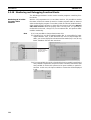
F Key: Pasting Function
Block Definitions in
Program
Move the cursor to the position at which to create the copied function block
instance in the Ladder Section Window, and press the F Key. This operation is
the same as selecting Insert - Function Block Invocation.
Enter Key: Inputting
Parameters
Position the cursor at the left of the input variable or input-output variable, or
at the right of the output variable and press the Enter Key. This operation is
the same as selecting Insert - Function Block Parameter.
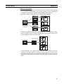
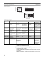
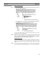
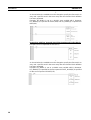
1-2
1-2-1
Function Blocks
Outline
A function block is a basic program element containing a standard processing
function that has been defined in advance. Once the function block has been
defined, the user just has to insert the function block in the program and set
the I/O in order to use the function.
As a standard processing function, a function block does not contain actual
addresses, but variables. The user sets addresses or constants in those variables. These address or constants are called parameters. The addresses
used by the variables themselves are allocated automatically by the CX-Programmer for each program.
11
Section 1-2
Function Blocks
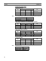
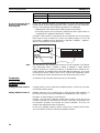
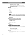
With the CX-Programmer, a single function block can be saved as a single file
and reused in other PLC programs, so standard processing functions can be
made into libraries.
Program 2
Copy of function block A
Function block A
Program 1
Variable
Copy of function block A
Standard
program section
written with
variables
Input
Variable Variable
Output
Output
Define in advance.
Insert in
program.
Set
Set
Copy of function block A
Save function
block as a file.
Convert to
library function.
Function
block A
Input
Variable Variable
Output
To another PLC program
Reuse.
1-2-2
Advantages of Function Blocks
Function blocks allow complex programming units to be reused easily. Once
standard programming is created in a function block and saved in a file, it can
be reused just by placing the function block in a program and setting the
parameters for the function block’s I/O. The ability to reuse existing function
blocks will save significant time when creating/debugging programs, reduce
coding errors, and make the program easier to understand.
Structured
Programming
Structured programs created with function blocks have better design quality
and require less development time.
Easy-to-read “Black Box”
Design
The I/O operands are displayed as variable names in the program, so the program is like a “black box” when entering or reading the program and no extra
time is wasted trying to understand the internal algorithm.
Use One Function Block
for Multiple Processes
Many different processes can be created easily from a single function block by
using the parameters in the standard process as input variables (such as
timer SVs, control constants, speed settings, and travel distances).
Reduce Coding Errors
Coding mistakes can be reduced because blocks that have already been
debugged can be reused.
Black-boxing Know-how
Read-protection can be set for function blocks to prevent programming knowhow from being disclosed.
Data Protection
The variables in the function block cannot be accessed directly from the outside, so the data can be protected. (Data cannot be changed unintentionally.)
Improved Reusability with
Variable Programming
The function block’s I/O is entered as variables, so it isn’t necessary to change
data addresses in a block when reusing it.
Creating Libraries
Processes that are independent and reusable (such as processes for individual steps, machinery, equipment, or control systems) can be saved as function block definitions and converted to library functions.
12
Section 1-2
Function Blocks
The function blocks are created with variable names that are not tied to actual
addresses, so new programs can be developed easily just by reading the definitions from the file and placing them in a new program.
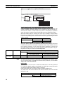
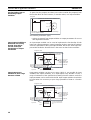
Supports Nesting and
Multiple Languages
Mathematical expressions can be entered in structured text (ST) language.
With CX-Programmer Ver. 6.0 and later versions, function blocks can be
nested. The function block nesting function allows just special processing to
be performed in a ST-language function block nested within a ladder-language function block.
Function block (ladder language)
Call (Nesting)
Function block (ST language)
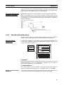
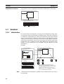
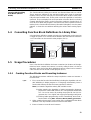
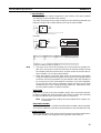
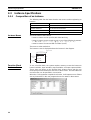
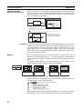
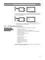
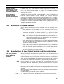
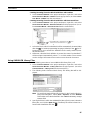
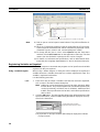
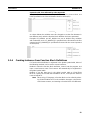
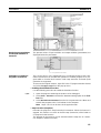
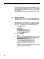
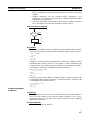
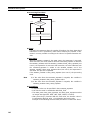
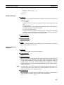
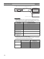
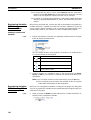
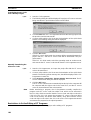
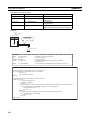
1-2-3
Function Block Structure
Function blocks consist of function block definitions that are created in
advance and function block instances that are inserted in the program.
Function Block
Definitions
Function block definitions are the programs contained in function blocks. Each
function block definition contains the algorithm and variable definitions, as
shown in the following diagram.
Function Block Definition
Example: CLOCK PULSE
Example: CLOCK PULSE
1. Algorithm
tim_b
TIMX tim_a OFF_TIME
Algorithm
tim_a
TIMX tim_b ON_TIME
Variable definitions
ENO
2. Variable Definitions
Usage
Name
Internal
Internal
Input
Input
tim_a
tim_b
ON_TIME
OFF_TIME
Type
TIMER
TIMER
INT
INT
1. Algorithm
Standardized programming is written with variable names rather than real I/O
memory addresses. In the CX-Programmer, algorithms can be written in
either ladder programming or structured text.
2. Variable Definitions
The variable table lists each variable’s usage (input, output, input-output, or
internal) and properties (data type, etc.). For details, refer to 1-3 Variables.
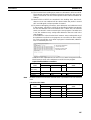
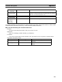
Number of Function Block
Definitions
The maximum number of function block definitions that can be created for one
CPU Unit is either 128 or 1,024 depending on the CPU Unit model.
13
Section 1-2
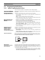
Function Blocks
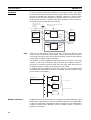
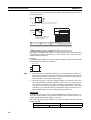
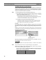
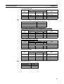
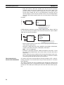
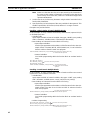
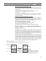
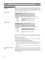
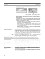
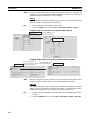
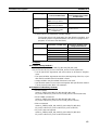
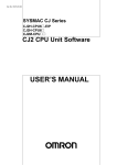
Instances
To use an actual function block definition in a program, create a copy of the
function block diagram and insert it in the program. Each function block definition that is inserted in the program is called an “instance” or “function block
instance.” Each instance is assigned an identifier called an “instance name.”
By generating instances, a single function block definition can be used to process different I/O data with the same function.
Not yet in program
and memory not yet
allocated
(abstract).
Function Block Definition FB1
Block instance in program with memory
allocated. (object)
Standard
program unit
with variable
names a, b, c,
etc.
Instance
Program
Insert in
program.
Automatic
allocation
Input
data
a
b
c
Output data
Output data
2. Parameters
Table defining usage
and properties of
variables a, b, c, etc.
Memory
used
Instance FB1_1 of function block definition FB1
1. Algorithm
Automatic
allocation
Memory
for FB1_2
Insert in
program.
Instance FB1_2 of function block definition FB1
Input
data
a
b
c
Note
Memory
for FB1_1
Different I/O data
can be processed
with the same
function.
Output data
Output data
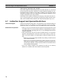
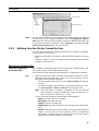
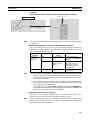
Instances are managed by names. More than one instance with the same
name can also be inserted in the program. If two or more instances have the
same name, they will use the same internal variables. Instances with different
names will have different internal variables.
For example, consider multiple function blocks that use a timer as an internal
variable. In this case all instances will have to be given different names. If
more than one instance uses the same name, the same timer would be used
in multiple locations, resulting in duplicated use of the timer.
If, however, internal variables are not used or they are used only temporarily
and initialized the next time an instance is executed, the same instance name
can be used to save memory.
instance_A
TIMER_FB
Function Block Definition
TIMER_FB
Variable Definitions
Internal variable: WORK_NUM
Use same internal variables.
instance_A
TIMER_FB
Use different internal variables.
instance_B
TIMER_FB
Number of Instances
14
Multiple instances can be created from a single function block definition. Up to
either 256 or 2,048 instances can be created for a single CPU Unit depending
on the CPU Unit model. The allowed number of instances is not related to the
number of function block definitions and the number of tasks in which the
instances are inserted.
Section 1-2
Function Blocks
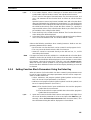
Parameters
Each time an instance is created, set the real I/O memory addresses or constants for input variables, output variables, and input-output variables used to
pass input data values to instances and obtain output data values from
instances. These addresses and constants are called parameters.
Instance of Function Block Definition A
Input 0.00
a
Input 3.00
c
Output 2.00
b
Set the constant or
output destination
address to which to pass
data.
Set the constants or
input source addresses
from which to pass data.
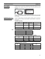
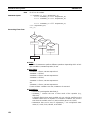
Using Input Variables and Output Variables
With input variables and output variables, it is not the input source address
itself, but the contents at the input address in the form and size specified by
the variable data type that is passed to the function block. In a similar fashion,
it is not the output destination address itself, but the contents for the output
address in the form and size specified by the variable data type that is passed
from the function block.
Even if an input source address (i.e., an input parameter) or an output destination address (i.e., an output parameter) is a word address, the data that is
passed will be the data in the form and size specified by the variable data type
starting from the specified word address.
Program
Instance of Function Block Definition A
Input D100
m
Input D200
n
k
Output D300
Examples:
If m is type WORD, one word of data from D100 will be passed to the
variable.
If n is type DWORD, two words of data from D200 and D201 will be
passed to the variable.
If k is type LWORD, four words of data from the variable will be passed
to the D300 to D303.
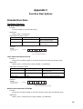
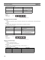
Note
(1) Only addresses in the following areas can be used as parameters: CIO
Area, Auxiliary Area, DM Area, EM Area (banks 0 to C), Holding Area,
and Work Area.
The following cannot be used: Index and Data Registers (both direct and
indirect specifications) and indirect addresses to the DM Area and EM
Area (both in binary and BCD mode).
(2) Local and global symbols in the user program can also be specified as
parameters. To do so, however, the data size of the local or global symbol
must be the same as the data size of the function block variable.
(3) When an instance is executed, input values are passed from parameters
to input variables before the algorithm is processed. Output values are
15
Section 1-2
Function Blocks
passed from output variables to parameters just after processing the algorithm. If it is necessary to read or write a value within the execution cycle of the algorithm, do not pass the value to or from a parameter. Assign
the value to an internal variable and use an AT setting (specified addresses).
!Caution If an address is specified in an input parameter, the values in the address are
passed to the input variable. The actual address data itself cannot be passed.
!Caution Parameters cannot be used to read or write values within the execution cycle
of the algorithm. Use an internal variable with an AT setting (specified
addresses). Alternatively, reference a global symbol as an external variable.
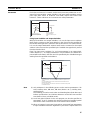
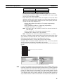
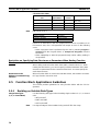
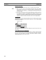
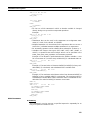
Using Input-Output Variables (In Out)
When using an input-output variable, set the address for the input parameter.
A constant cannot be set. The address set for the input parameter will be
passed to the function block. If processing is performed inside the function
block using the input-output variable, the results will be written to I/O starting
at the address set for the size of the variable.
Program
Instance of function block definition A
Automatically set.
Input D200
a
a
Output D200
Address passed.
Address passed.
“a” changed by function
block processing.
D200
D201
Variable “a”
Processing is performed inside the function block using variable
“a.” The resulting value is written to I/O memory for the size of
variable “a” starting at address D200.
Note
16
Input-output variables are specified in a CX-Programmer variable table by
selecting “In Out” for the variable usage.
Section 1-2
Function Blocks
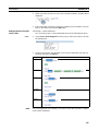
n Reference Information
A variety of processes can be created easily from a single function block by
using parameter-like elements (such as fixed values) as input variables and
changing the values passed to the input variables for each instance.
Example: Creating 3 Instances from 1 Function Block Definition
Instance
CASCADE_01
Algorithm
Cyclic task 0
CASCADE_01
P_On
EN
&20
Internal and I/O
variables
&10
CONTROL
ENO
1.0
ON_TIME
OFF_TIME
Function Block Definition
Example: CONTROL
Algorithm
Variables
Example:
There are 3 FB
instances and each
has its own I/O and
internal variables.
Instance
CASCADE_02
Algorithm
CASCADE_02
P_On
EN
&15
Internal and I/O
variables
Instance
CASCADE_03
Algorithm
&10
CONTROL
ENO
1.1
ON_TIME
OFF_TIME
Cyclic task 1
CASCADE_03
P_On
EN
&7
Internal and I/O
variables
&8
CONTROL
ENO
1.2
ON_TIME
OFF_TIME
If internal variables are not used, if processing will not be affected, or if the
internal variables are used in other locations, the same instance name can be
used at multiple locations in the program.
Cyclic taskCASCADE
0
P_On
&100
The same instance can be
used at multiple locations.
&130
CONTROL
EN
ENO
1.0
PARA_1
PARA_2
Function block definition
Example: CONTROL
Algorithm
Variables
Instance
CASCADE
Algorithm
Internal and I/O
variables
P_On
&50
&150
CASCADE
CONTROL
EN
ENO
1.1
PARA_1
PARA_2
Cyclic taskCASCADE
1
P_On
&100
&200
CONTROL
EN
ENO
1.2
PARA_1
PARA_2
Some precautions are required when using the same memory area. For
example, if the same instance containing a timer instruction is used in more
than one program location, the same timer number will be used causing coil
duplication, and the timer will not function properly if both instructions are executed.
17
Section 1-3
Variables
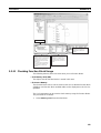
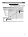
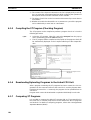
Registration of Instances
Each instance name is registered in the global symbol table as a file name.
Program
Instance (sample) of function block definition A
a
b
c
The instance is registered in the
global symbol table with the instance
name as the symbol name.
Name
Data type
sample FB [FunctionBlock1]
The function block definition
name is registered after FB in
square parentheses [ ].
Instance name
1-3
1-3-1
Address/
value
N/A[Auto]
Variables
Introduction
In a function block, the addresses (see note) are not entered as real I/O memory addresses, they are all entered as variable names. Each time an instance
is created, the actual addresses used by the variable are allocated automatically in the specified I/O memory areas by the CX-Programmer. Consequently, it isn’t necessary for the user to know the real I/O memory addresses
used in the function block, just as it isn’t necessary to know the actual memory allocations in a computer. A function block differs from a subroutine in this
respect, i.e., the function block uses variables and the addresses are like
“black boxes.”
Example:
Program
Function block definition A
Instance of function block definition A
Standard program section with
variable names a, b, c, etc.
b
a
c
MOV
Table indicating usage and
properties of variables a, b, c, etc.
Usage: Inputs
a
c
AT
Initial Value Retained
BOOL
BOOL
Usage: Outputs
Properties:
Name Type
BOOL
b
Note
18
AT
Input 0.00
a
Input 3.00
c
b
Output 2.00
Specify inputs and outputs
at the same time.
Status of 0.00 (1 or 0) is
passed to a.
0.00 1
a
1
Status of b (1 or 0) is
passed to 2.00.
b
1
2.00
1
Status of 3.00 (1 or 0) is
passed to c.
Properties:
Name Type
Insert in
program.
Initial Value Retained
3.00 0
c
0
The system automatically allocates the
addresses used by variables a, b, and c. For
example, when W100 to W120 is set as the
system’s non-retained memory area, bit
addresses such as a = W10000, b = W10001,
and c = W10002 will be allocated.
Constants are not registered as variables. Enter constants directly in instruction operands.
Section 1-3
Variables
• Ladder programming language: Enter hexadecimal numerical values
after the # and decimal values after the &.
• Structured text (ST language): Enter hexadecimal numerical values after 16# and enter decimal numerical values as is.
Exception: Enter directly or indirectly specified addresses for Index Registers
IR0 to IR15 and Data Registers DR0 to DR15 directly into the instruction
operand.
1-3-2
Variable Usage and Properties
Variable Usage
The following variable types (usages) are supported.
Internals:
Internal variables are used only within an instance. They cannot
be used pass data directly to or from I/O parameters.
Inputs:
Input variables can input data from input parameters outside of
the instance. The default input variable is an EN (Enable) variable, which passes input condition data.
Outputs:
Output variables can output data to output parameters outside of
the instance. The default output variable is an ENO (Enable Out)
variable, which passes the instance’s execution status.
In Out:
Input-output variables can input data from input parameters outside of the instance and can return the results of processing in a
function block instance to external parameters.
Externals: External variables are either system-defined variables registered
in advance with the CX-Programmer, such as the Condition Flags
and some Auxiliary Area bits, or user-defined global symbols for
use within instances.
For details on variable usage, refer to the section on Variable Type (Usage)
under Variable Definitions in 2-1-2 Function Block Elements.
The following table shows the number of variables that can be used and the
kind of variable that is created by default for each of the variable usages.
1-3-3
Variable Properties
Variables have the following properties.
Variable Name
The variable name is used to identify the variable in the function block. It
doesn’t matter if the same name is used in other function blocks.
Note
Data Type
The variable name can be up to 30,000 characters long, but must not begin
with a number. Also, the name cannot contain two underscore characters in a
row. The character string cannot be the same as that of a an index register
such as in IR0 to IR15. For details on other restrictions, refer to Variable Definitions in 2-1-2 Function Block Elements.
Select one of the following data types for the variable:
BOOL, INT, UINT, DINT, UDINT, LINT, ULINT, WORD, DWORD, LWORD,
REAL, LREAL, TIMER, COUNTER, and STRING
For details on variable data types, refer to Variable Definitions in 2-1-2 Function Block Elements.
AT Settings (Allocation to
an Actual Addresses)
It is possible to set a variable to a particular I/O memory address rather than
having it allocated automatically by the system. To specify a particular
address, the user can input the desired I/O memory address in this property.
This property can be set for internal variables only. Even if a specific address
is set, the variable name must still be used in the algorithm.
19
Section 1-3
Variables
Refer to Variable Definitions in 2-1-2 Function Block Elements for details on
AT settings and 2-5-3 AT Settings for Internal Variables for details on using AT
settings.
Array Settings
A variable can be treated as a single array of data with the same properties.
To convert a variable to an array, specify that it is an array and specify the
maximum number of elements.
This property can be set for internal variables and input-output variables only.
Only one-dimensional arrays are supported by the CX-Programmer Ver. 5.0
and later versions.
• Setting Procedure
Click the Advanced Button, select the Array Variable option, and input the
maximum number of elements.
• When entering an array variable name in the algorithm in a function block
definition, enter the array index number in square brackets after the variable number.
For details on array settings, refer to Variable Definitions in 2-1-2 Function
Block Elements.
Initial Value
This is the initial value set in a variable before the instance is executed for the
first time. Afterwards, the value may be changed as the instance is executed.
For example, set a boolean (BOOL) variable (bit) to either 1 (TRUE) or 0
(FALSE). Set a WORD variable to a value between 0 and 65,535 (between
0000 and FFFF hex).
If an initial value is not set, the variable will be set to 0. For example, a boolean variable would be 0 (FALSE) and a WORD variable would be 0000 hex.
Retain
Select the Retain Option if you want a variable’s data to be retained when the
PLC is turned ON again and when the PLC starts operating.
• Setting Procedure
Select the Retain Option.
Size
1-3-4
When a STRING variable is used, the size required to store the text string can
be set to between 1 and 255 characters.
Variable Properties and Variable Usage
The following table shows which properties must be set, can be set, and cannot be set, based on the variable usage.
Property
Internals
Must be set.
Must be set.
Can be set.
Name
Data Type
AT (specified
address)
Array specification
Initial Value
Must be set.
Can be set.
Retained
Can be set.
Size
Can be set.
(See note 2.)
Variable usage
Inputs
Outputs
In Out
Must be set.
Must be set.
Must be set.
Must be set.
Must be set.
Must be set.
Cannot be set. Cannot be set. Cannot be set.
Cannot be set.
Cannot be set.
(See note 1.)
Cannot be set.
(See note 1.)
Cannot be set.
Cannot be set. Must be set.
Can be set.
Cannot be set.
Can be set.
Cannot be set. Cannot be set.
(1) The value of the input parameter will be given.
(2) Valid only for STRING variables.
20
Cannot be set.
Section 1-3
Variables
1-3-5
Internal Allocation of Variable Addresses
When an instance is created from a function block definition, the CX-Programmer internally allocates addresses to the variables. Addresses are allocated
to all of the variables registered in the function block definition except for variables that have been assigned actual addresses with the AT Settings property.
FB instance areas
Program
Instance of function block definition A
Non-retained area
Starting address 15
Input 0.00
a
b
Output 2.00
t
Output 5.00
Note: Variable c is an internal
variable, so it is not displayed.
Usage: Inputs
Properties:
Name Type
AT
a
BOOL
Initial Value Retained
0
CIO, H, W,
D, or E Area
Retained area
Starting address 15
Name Type
b
t
AT
Initial Value Retained
BOOL
TIMER
c
Setting Internal Allocation
Areas for Variables
AT
Initial Value Retained
BOOL 2000.00
Size (words)
Timer area
T Area
Size (Completion
Flags)
C Area
Size (Completion
Flags)
Counter area
YES
Usage: Internals
Properties:
Name Type
0
H, D, or E
Area
Starting address
Usage: Outputs
Properties:
Size (words)
Automatic allocation of
addresses by system
Starting
address
Example
2000.00
Manual allocation of address to
variable in FB by AT Settings option.
The user sets the function block instance areas in which addresses are allocated internally by the system. The variables are allocated automatically by
the system to the appropriate instance area set by the user.
Setting Procedure
Select Function Block/SFC Memory - Function Block/SFC Memory Allocation from the PLC Menu. Set the areas in the Function Block/SFC Memory
Allocation Dialog Box.
21
Section 1-3
Variables
Function Block Instance Areas
CJ2-series CPU Units
FB Instance
Area
Note
Non Retain
Default value
Start address End address
H512
H1407
Size
896
Retain
Timers
Counters
H1408
T3072
C3072
128
1024
1024
H1535
T4095
C4095
Applicable memory
areas
CIO, WR, HR, DM,
EM (See note.)
HR, DM, EM (See note.)
TIM
CNT
Force-setting/resetting is enabled when the following EM banks are specified:
CJ2H-CPU64(-EIP)/-CPU65(-EIP)
CJ2H-CPU66(-EIP)
CJ2H-CPU67(-EIP)
CJ2H-CPU68(-EIP)
EM bank 3
EM banks 6 to 9
EM banks 7 to E
EM banks 11 to 18
CS/CJ-series CPU Units Ver. 3.0 or Later, and NSJ Controllers
FB Instance
Area
Non Retain
Retain
Timers
Counters
Default value
Start address End address
H512
H1407
H1408
H1535
T3072
T4095
C3072
C4095
Size
896
128
1024
1024
Applicable memory
areas
CIO, WR, HR, DM, EM
HR, DM, EM
TIM
CNT
FQM1 Flexible Motion Controllers
FB Instance
Area
Non Retain
Retain
Timers
Counters
Default value
Start address End address
5000
5999
None
T206
T255
C206
C255
Applicable memory
areas
Size
1000
CIO, WR, DM
50
50
TIM
CNT
CP-series CPU Units
FB Instance
Area
Note
Non Retain
Default value
Start address End address
H512
H1407
Size
896
Retain
Timers
Counters
H1408
T3072
C3072
128
1024
1024
DM area of CP1L-L
Address
D0000 to D9999
D10000 to D31999
D32000 to D32767
22
H1535
T4095
C4095
CP1L-L
Provided
Not Provided
Provided
Applicable memory
areas
CIO, WR, HR, DM (See
note.)
HR, DM (See note.)
TIM
CNT
Section 1-4
Converting Function Block Definitions to Library Files
Function Block Holding
Area Words (H512 to
H1535)
1-4
The Function Block Holding Area words are allocated from H512 to H1535.
These words are different to the standard Holding Area used for programs
(H000 to H511) and are used only for the function block instance area (internally allocated variable area). These words cannot be specified as instruction
operands. They are displayed in red if input when a function block is not being
created. Although the words can be input when creating a function block, an
error will occur when the program is checked. If this area is specified not to be
retained in the Function Block Memory Allocation Dialog Box, turn the power
ON/OFF or clear the area without retaining the values when starting operation.
Converting Function Block Definitions to Library Files
A function block definition created using the CX-Programmer can be stored as
a single file known as a function block definition file with filename extension
*.cxf. These files can be reused in other projects (PLCs).
Project
Project
Function block definition
Example: CLOCK_PULSE
Function block definition
Example: CLOCK_PULSE
1. Algorithm
1. Algorithm
Save
tim_b
Read
TIMX tim_a OFF_TIME
tim_b
TIMX tim_a OFF_TIME
tim_a
tim_a
TIMX tim_b ON_TIME
TIMX tim_b ON_TIME
ENO
ENO
2. Variable Definitions
Usage
Name
Internal
Internal
Input
Input
1-5
tim_a
tim_b
ON_TIME
OFF_TIME
2. Variable Definitions
Usage
Name
Type
Internal
Internal
Input
Input
TIMER
TIMER
INT
INT
tim_a
tim_b
ON_TIME
OFF_TIME
Type
TIMER
TIMER
INT
INT
Function block
definition file (.cxf)
Usage Procedures
Once a function block definition has been created and an instance of the algorithm has been created, the instance is used by calling it when it is time to
execute it. Also, the function block definition that was created can be saved in
a file so that it can be reused in other projects (PLCs).
1-5-1
Creating Function Blocks and Executing Instances
The following procedure outlines the steps required to create and execute a
function block.
1,2,3...
1. First, create the function block definition including the algorithm and variable definitions in ladder program or ST language. Alternatively, insert a
function block library file that has been prepared in advance.
Note (a) Create the algorithm entirely with variable names.
(b) When entering the algorithm in ladder programming language,
project files created with versions of CX-Programmer earlier than
Ver. 5.0 can be reused by reading the project file into CX-Programmer Ver. 5.0 or higher and copying and pasting useful parts.
(c) Existing ladder programming can be automatically turned into a
function block using Edit - Function Block (ladder) generation.
2. When creating the program, insert copies of the completed function block
definition. This step creates instances of the function block.
3. Enter an instance name for each instance.
23
Section 1-5
Usage Procedures
4. Set the variables’ input source addresses and/or constants and output
destination addresses and/or constants as the parameters to pass data for
each instance.
5. Select the created instance, select Function Block Memory - Function
Block Memory Allocation from the PLC Menu, and set the internal data
area for each type of variable.
6. Transfer the program to the CPU Unit.
7. Start program execution in the CPU Unit and the instance will be called and
executed if their input conditions are ON.
Function block definition A
Program
Input
condition
1. Algorithm
Standard
program section
with variable
names a, b, c,
etc.
The instance is
executed if the input
condition is established.
Insert in
program.
Input 0.00
3. Input instance name
Instance of function block definition A
5. The system automatically allocates
the addresses used by these
variables. Set the data area in
which these addresses are allocated.
Output 2.00
a
b
c
Output 3.00
2. Variables
Table defining usage
and properties of
variables a, b, c, etc.
1-5-2
4. Specify the input source and
output destination addresses.
Reusing Function Blocks
Use the following procedure to save a function block definition as a file and
use it in a program for another PLCs.
1,2,3...
1. Select the function block that you want to save and save it as a function
block definition file (*.cxf).
2. Open the other PLC’s project and open/read the function block definition
file (*.cxf) that was saved.
3. Insert the function block definition in the program when creating the new
program.
Function block definition A
Program
1. Algorithm
Input
condition
Standard
program section
with variable
names a, b, c,
etc.
Input 1.00
2. Variables
Table defining usage
and properties of
variables a, b, c, etc.
Instance of function block definition A
a
b
Output 5.00
c
Output 6.00
Read and
insert.
Save
Function
block
definition
A
Function block
definition file (*.cxf)
Note
24
In the CX-Programmer Ver. 5.0, each function block definition can be compiled and checked as a program. We recommend compiling to perform a program check on each function block definition file before saving or reusing the
file.
Section 1-6
Version Upgrade Information
1-6
Version Upgrade Information
Refer to the CX-Programmer Operation Manual (W446) for information on
upgraded functions other than those for function blocks and structure text.
Ver. 9.2 to 9.3 Upgrade Information
Changed ST Editor View
• Added the indication of line numbers on the ST Editor View. And you can
also specify a line number to jump there.
• Functions and registered Symbols are selectable from Word Lists.
• When you press the Tab key while the start function of a Control Statement is selected, you can enter the frame of the Control Statement very
easily.
• Red wavy lines indicate ST syntax errors in a program. No programming
check is required.
Smart input on FB Ladder
View
You can use the Smart Input Mode on the FB Ladder View in the same way as
on the Task Ladder View.
Ver. 9.1 to 9.2 Upgrade Information
Improvements on
Structures
For the CJ2 CPU Units, the available range of structures is expanded.
• Structures (structure variables, structure member variables, and structure
array variables) are made available in ST (Structured Text) programs.
• You can register and use structure variables as an external variable of FB
(Function Block) ladder and ST.
Support of Structure Variables - Comparison with Previous Versions
Usage
Global symbol table
Ladder program
Local symbol table
Section view
ST program
Local symbol table
ST editor
SFC program
Local symbol table
SFC chart view
Sub-chart view
Sub-chart symbol table
Action ladder view
Action ST view
Transition ladder view
Transition ST view
FB ladder
Variables
Internal variables
Input variables
Output variables
Input-Output variables
External variables
FBST
Variables
Internal variables
Input variables
Output variables
Input-Output variables
External variables
Version 9.1 or earlier
Yes
Yes
Yes
No
No
No
No
No
No
No
No
No
No
Yes
No
No
Yes
No
No
No
No
No
No
Version 9.2 or higher
Yes
Yes
Yes
Yes
Yes
Yes
No
No
Yes
Yes
Yes
Yes
Yes
Yes
No
No
Yes
Yes
Yes
No
No
Yes
Yes
25
Section 1-6
Version Upgrade Information
Improvements on TIMER/
COUNTER Type Variables
For the CJ2 CPU Units, the available range of TIMER/COUNTER type variables is expanded.
• The TIMER/COUNTER type variables are made available in ST programs. You can use the timer/counter completion flags and the timer/
counter present values in ST programs.
• In the ST program, you can start and stop the timers/counters.
• You can register and use TIMER/COUNTER type variables as an external
variable of FB.
Support of TIMER/COUNTER Type Variables - Comparison with Previous Versions
Usage
Global symbol table
Ladder program
ST program
SFC program
FB ladder
Variables
FBST
Variables
Local symbol table
Section view
Local symbol table
ST editor
Local symbol table
SFC chart view
Sub-chart view
Sub-chart symbol table
Action ladder view
Action ST view
Transition ladder view
Transition ST view
Internal variables
Input variables
Output variables
Input-Output variables
External variables
Internal variables
Input variables
Output variables
Input-Output variables
External variables
Version 9.1 or earlier
Yes
Yes
Yes
Yes
No
Yes
No
No
Yes
Yes
No
Yes
No
Yes
No
No
No
No
No
No
No
No
No
Version 9.2 or higher
Yes
Yes
Yes
Yes
Yes
Yes
No
No
Yes
Yes
Yes
Yes
Yes
Yes
No
No
No
Yes
Yes
No
No
No
Yes
Version 9.0 to 9.1 Upgrade Information
The new CPU Unit models of CJ2M-CPU@@ supporting function blocks and
structured text are now supported.
When the PLC model is set to the CJ2M, FB Program Area usage can be displayed using the memory view function.
Version 8.3 to 9.0 Upgrade Information
Data Structures Supported as Symbol Data Types
Version 8.3
Data structures are not supported.
Version 9.0
CJ2 CPU Units now support data structures as symbol data type.
Version 8.0 to 8.1 Upgrade Information
The new PLC models of CJ2H-CPU6@ supporting function blocks and structured text are now supported.
26
Section 1-6
Version Upgrade Information
Version 7.2 to 8.0 Upgrade Information
The new PLC models of CJ2H-CPU6@-EIP supporting function blocks and
structured text are now supported.
Version 7.0 to 7.2 Upgrade Information
Improved Support for
Function Blocks and
Structured Text
For details on the other improvements to CX-Programmer functions in this
upgrade, refer to the CX-Programmer Operation Manual (W446).
n
IEC61131-3 Language Improvements
Support has been improved for the structured text and SFC languages, which
are IEC61131-3 languages. Ladder, structured text (ST), and SFC programming can be combined freely, so that the best language for each process can
be used, which reduces program development time and makes the program
easier to understand.
Support for ST Language in the Program (Task Allocation)
Version 7.0
The ST language could be used only in function
blocks.
Version 7.2
The ST language can be used in programs (task allocation) other than
function blocks. (ST programs can be allocated to tasks.)
Other programming languages can be combined freely in a single user
program. With this capability, numerical calculations can be written as
ST programs, and other processing can be written as ladder or SFC
programs.
Note Structured text is supported only by CS/CJ-series CPU Units with
unit version 4.0 or later. It is not supported by CP-series CPU
Units.
Comparison of Function Block Definitions and ST Programs
Version 7.0
Function block definitions could not be compared.
Version 7.2
• Function block definitions can be compared. With this capability, it is
easy to check for differences in function block definitions in programs.
• ST programs can also be compared.
Version 6.1 to 7.0 Upgrade Information
Convenient Functions to Convert Ladder Diagrams to Function Blocks
Version 6.1
Ladder programming can be copied into a function block definition to create a function block.
The symbols and addresses in the ladder programming, however, have to be checked and
input variables, internal variables, and output
variables have to be identified and manually registered.
Version 7.0
One or more program sections can be selected from the program and
then Function Block (ladder) generation selected from the menu to
automatically create a function block definition and automatically allocate variables according to symbols and addresses in the program sections. (Allocations can later be changed as required.) This enables
legacy programming to be easily converted to function blocks.
Online Function Block Editing
Version 6.1
Function block definitions (i.e., the algorithms
and variable tables) cannot be changed online
when the PLC is running. (Only I/O parameters
for function block instances can be changed.)
Version 7.0
The algorithms and variables tables for function blocks can be changed
while the PLC is operation. (See note.) This enables debugging and
changing function block definitions in systems that cannot be stopped,
such as systems that operate 24 hours a day.
Operation: Right-click the function block definition in the Work Space
and select FB Online Edit - Begin from the pop-up menu.
Note Function block instances cannot be added.
Note This function cannot be used for simulations on CX-Simulator.
27
Section 1-6
Version Upgrade Information
Support for STRING Data Type and Processing Functions in Standard Text Programs
Version 6.1
Version 7.0
• The STRING data type (text) cannot be used in • The STRING data type (text) can be used in ST programming. This
enables, for example, substituting a text string for a variable (e.g., a :=
ST programming. (See note.)
'@READ';) to easily set a variable containing text (i.e., ASCII charac• There are no text processing functions supters). In doing this, the user does not have to be concerned with the
ported for ST programming.
ASCII code or code size.
• Even in a ladder program, the user has to con•
Text processing functions are supported for ST programming, includsider the ASCII code and code size of text for
display messages and no-protocol communica- ing text extraction, concatenation, and searching. This enables easily
tions (see note) when executing string process- processing text strings and display messages in ST programming
inside function blocks.
ing instructions, data conversion instructions,
• Functions are also supported for sending and receiving text strings.
and serial communications instructions.
This enables easily processing no-protocol communications using ST
Note The user can use the PLC memory funcprogramming in functions blocks without being concerned with ASCII
tion of the CX-Programmer to input text
strings in I/O memory. The data size in I/O codes.
memory, however, must be considered.
Support for Input-Output Variables
Version 6.1
• Input-output variables cannot be used in function blocks. (Only input variables, internal variables, and output variables can be used.)
• Arrays cannot be specified for input variables.
• Values are passed from input parameters to
input variables.
Version 7.0
• Input-output variables can be used in function blocks.
• Input-output variables can be specified as arrays.
• Addresses are passed from input parameters to input variables
instead of values. This enables using input-output variable arrays
inside function blocks to enable easily passing large amounts of data
to function blocks using the input parameters.
Version 6.0 to 6.1 Upgrade Information
Support for NSJ-series
NSJ Controllers
The PLC model (“device type”) can be set to “NSJ” and the CPU type can be
set to the G5D.
Support for FQM1 Unit
Version 3.0
The new models of the FQM1 Flexible Motion Controller are now supported
(i.e., the FQM1-CM002 Coordinator Module and the FQM1-MMA22/MMP22
Motion Control Modules).
Instance ST/Ladder Program Simulation Function
Previous version (Ver. 6.0)
The CX-Simulator could be used to execute a
ladder program step (Step Run), execute steps
continuously (Continuous Step Run), execute a
single cycle (Scan Run), and set I/O break point
conditions.
New version (Ver. 6.1)
The Step Run, Continuous Step Run, Scan Run, and Set/Clear Break
Point functions can be executed as CX-Programmer functions.
All of these functions can be used with ladder programs and ladder/ST
programs in function blocks.
Note The CX-Simulator Ver. 1.6 (sold separately) must be installed in
order to use these functions.
Note I/O break conditions cannot be set.
Improved Function Block Functions
Monitoring ST Programs in Function Blocks
Previous version (Ver. 6.0)
The operation of ST programs within function
block instances could not be monitored while
monitoring the program online.
(It was possible to check the contents of a function block definition’s program and monitor the I/
O status of a function block instance’s ladder
diagram.)
28
New version (Ver. 6.1)
The status of a function block instance’s ST program can be monitored
while monitoring the program.
To monitor the ST program’s status, either double-click the function
block instance or right-click the instance and select Monitor FB
Instance from the pop-up menu. At this point, it will be possible to
change PVs and force-set/reset bits.
Note Online editing is not supported.
Section 1-6
Version Upgrade Information
Password Protection of Function Blocks
Previous version (Ver. 6.0)
The function block properties could be set to
prevent the display of a function block definition’s program.
New version (Ver. 6.1)
The following two kinds of password protection can be set.
• Password protection restricting both reading and writing.
• Password protection restricting writing only.
Version 5.0 to 6.0 Upgrade Information
Nesting Function Blocks
Previous version (Ver. 5.0)
New version (Ver. 6.0)
A function block could not be called from another A function block can be called from another function block (nested). Up
function block. (Nesting not supported.)
to 8 nesting levels are supported.
The languages of the calling function block and called function block
can be either ladder language or ST language.
The nesting level relationship between function blocks can be displayed
in a directory tree format. When function blocks are nested, just one
Function Block Library file (.cxf extension) is stored for the calling function block and its called (nested) function block definitions.
I/O Bit Monitor Support for Ladder Programs in Function Blocks
Previous version (Ver. 5.0)
The I/O status of a function block instance’s ladder diagram could not be monitored while monitoring the program online.
(It was only possible to check the program in the
function block definition.)
New version (Ver. 6.0)
The I/O status of a function block instance’s ladder diagram can be
monitored while monitoring the program online.
To monitor the I/O status, either double-click the function block instance
or right-click the instance and select Monitor FB Ladder Instance
from the pop-up menu. At this point, it will be possible to monitor the
status of I/O bits and the content of words, change PVs, force-set/reset
bits, and monitor differentiation (ON/OFF transitions) of bits.
Note Online editing is not supported and timer/counter SVs cannot be
changed.
Registering and Monitoring Function Block Instance Variables in a Watch Window
Previous version (Ver. 5.0)
To register a function block instance’s variable in
a Watch Window, it was necessary to display the
Watch Window, double-click the window, and
select the desired variable from a pull-down list.
New version (Ver. 6.0)
Multiple variables in a function block instance can be easily registered
together in the Watch Window. The FB variables registration Dialog Box
can be displayed with any of the following methods and the variables
can be registered together in that Dialog Box.
• Right-click the function block instance and select Register in Watch
Window from the pop-up menu.
• Select the desired function block instance in the program or variable
table and either copy/paste or drag/drop the instance into the Watch
Window.
• Move the cursor to an empty line in the Watch Window and select
Register in Watch Window from the pop-up menu.
Other Function Block Improvements
• The cross-reference pop-up function is supported in ladder programs
within function blocks.
• The ST language help program can be started from the pop-up menu in
ST Editor.
• A function block’s definitions can be opened just by double-clicking the
function block instance.
• The cursor automatically moves down after a function block instance’s
parameter input is confirmed.
29
Version Upgrade Information
30
Section 1-6
SECTION 2
Function Block Specifications
This section provides specifications for reference when using function blocks, including specifications on function blocks,
instances, and compatible PLCs, as well as usage precautions and guidelines.
2-1
2-2
2-3
2-4
Function Block Specifications . . . . . . . . . . . . . . . . . . . . . . . . . . . . . . . . . . . .
32
2-1-1
Function Block Specifications . . . . . . . . . . . . . . . . . . . . . . . . . . . . .
32
2-1-2
Function Block Elements . . . . . . . . . . . . . . . . . . . . . . . . . . . . . . . . .
33
Data Types Supported in Function Blocks . . . . . . . . . . . . . . . . . . . . . . . . . . .
43
2-2-1
Basic Data Types . . . . . . . . . . . . . . . . . . . . . . . . . . . . . . . . . . . . . . .
43
2-2-2
Derivative Data Types. . . . . . . . . . . . . . . . . . . . . . . . . . . . . . . . . . . .
43
Instance Specifications . . . . . . . . . . . . . . . . . . . . . . . . . . . . . . . . . . . . . . . . . .
44
2-3-1
Composition of an Instance . . . . . . . . . . . . . . . . . . . . . . . . . . . . . . .
44
2-3-2
Parameter Specifications. . . . . . . . . . . . . . . . . . . . . . . . . . . . . . . . . .
49
2-3-3
Operating Specifications. . . . . . . . . . . . . . . . . . . . . . . . . . . . . . . . . .
51
Programming Restrictions. . . . . . . . . . . . . . . . . . . . . . . . . . . . . . . . . . . . . . . .
53
2-4-1
Ladder Programming Restrictions . . . . . . . . . . . . . . . . . . . . . . . . . .
53
2-4-2
ST Programming Restrictions. . . . . . . . . . . . . . . . . . . . . . . . . . . . . .
55
2-4-3
Programming Restrictions . . . . . . . . . . . . . . . . . . . . . . . . . . . . . . . .
56
Function Block Applications Guidelines . . . . . . . . . . . . . . . . . . . . . . . . . . . .
58
2-5-1
Deciding on Variable Data Types . . . . . . . . . . . . . . . . . . . . . . . . . . .
58
2-5-2
Determining Variable Types
(Inputs, Outputs, In Out, Externals, and Internals). . . . . . . . . . . . . .
59
2-5-3
AT Settings for Internal Variables. . . . . . . . . . . . . . . . . . . . . . . . . . .
61
2-5-4
Array Settings for Input-Output Variables and Internal Variables . .
61
2-5-5
Specifying Addresses Allocated to Special I/O Units . . . . . . . . . . .
63
2-5-6
Using Index Registers. . . . . . . . . . . . . . . . . . . . . . . . . . . . . . . . . . . .
64
2-6
Precautions for Instructions with Operands Specifying the First
or Last of Multiple Words . . . . . . . . . . . . . . . . . . . . . . . . . . . . . . . . . . . . . . . .
67
2-7
Instruction Support and Operand Restrictions . . . . . . . . . . . . . . . . . . . . . . . .
70
2-8
CPU Unit Function Block Specifications . . . . . . . . . . . . . . . . . . . . . . . . . . . .
71
2-8-1
Specifications . . . . . . . . . . . . . . . . . . . . . . . . . . . . . . . . . . . . . . . . . .
71
2-8-2
2-5
2-9
Operation of Timer Instructions . . . . . . . . . . . . . . . . . . . . . . . . . . . .
77
Number of Function Block Program Steps and Instance Execution Time . . .
78
2-9-1
Number of Function Block Program Steps. . . . . . . . . . . . . . . . . . . .
78
2-9-2
Function Block Instance Execution Time. . . . . . . . . . . . . . . . . . . . .
79
31
Section 2-1
Function Block Specifications
2-1
2-1-1
Function Block Specifications
Function Block Specifications
Item
Number of function
block definitions
Description
CJ2H CPU Units:
• CJ2H-CPU6@(-EIP): 2,048 max. per CPU Unit
CJ2M CPU Units:
• CJ2M-CPU@1/@2/@3: 256 max. per CPU Unit
• CJ2M-CPU@4/@5: 2,048 max. per CPU Unit
CS1-H/CJ1-H CPU Units:
• Suffix -CPU44H/45H/64H/65H/66H/67H/64H-R/65H-R/
66H-R/67H-R: 1,024 max. per CPU Unit
• Suffix -CPU42H/43H/63H: 128 max. per CPU Unit
CJ1M CPU Units:
• CJ1M-CPU11/12/13/21/22/23: 128 max. per CPU Unit
CP1H CPU Units:
• CP1H-XA/X/Y: 128 max. per CPU Unit
CP1L CPU Units:
• CP1L-M/L: 128 max. per CPU Unit
NSJ Controllers:
• All models: 1,024 max. per Controller
FQM1 Flexible Motion Controllers:
• FQM1-CM002/MMA22/MMP22: 128 max. per Controller
Number of instances
CJ2H CPU Units:
• CJ2H-CPU6@(-EIP): 2,048 max. per CPU Unit
CJ2M CPU Units:
• CJ2M-CPU@1/@2/@3: 256 max. per CPU Unit
• CJ2M-CPU@4/@5: 2,048 max. per CPU Unit
CS1-H/CJ1-H CPU Units:
• Suffix -CPU44H/45H/64H/65H/66H/67H/64H-R/65H-R/
66H-R/67H-R: 2,048 max. per CPU Unit
• Suffix -CPU42H/43H/63H: 256 max. per CPU Unit
CJ1M CPU Units:
• CJ1M-CPU11/12/13/21/22/23: 256 max. per CPU Unit
CP1H CPU Units:
• CP1H-XA/X/Y: 256 max. per CPU Unit
CP1L CPU Units:
• CP1L-M/L: 256 max. per CPU Unit
NSJ Controllers:
• All models: 2,048 max. per Controller
FQM1 Flexible Motion Controllers:
• FQM1-CM002/MMA22/MMP22: 256 max. per Controller
Number of instance
• CX-Programmer Ver. 5.0:
nesting levels
Nesting is not supported.
• CX-Programmer Ver. 6.0 and later versions:
Supports nesting up to 8 levels. (The instance called from
the program is counted as one nesting level.)
Maximum number of variables per function block definition
Number of variables
used in a function block • Input-output variables: 16 max.
(not including internal
• Input variables + input-output variables: 64 max.
variables, external vari• Output variables + input-output variables: 64 max.
ables, EN, and EN0)
32
Section 2-1
Function Block Specifications
2-1-2
Function Block Elements
The following table shows the items that must be entered by the user when
defining function blocks.
Item
Function block
definition name
Language
Variable definitions
Algorithm
Comment
Function Block
Definition Name
Description
The name of the function block definition
The programming language used in the function block definition. Select ladder programming or structured text
Variable settings, such as operands and return values,
required when the function block is executed
• Type (usage) of the variable
• Name of the variable
• Data type of the variable
• Initial value of the variable
Enter the programming logic in ladder or structured text.
• Enter the programming logic using variables.
• Input constants directly without registering in variables.
Function blocks can have comments.
Each function block definition has a name. The names can be up to 64 characters long and there are no prohibited characters. The default function block
name is FunctionBlock@, where @ is a number (assigned in order).
Function block definition name
CLOCK PULSE
EN
ENO
(BOOL) (BOOL)
ON_TIME
(INT)
OFF_TIME
(INT)
Language
Select either ladder programming language or structured text (ST language).
Note
(1) For details on ST language, refer to SECTION 5 Structured Text (ST)
Language Specifications in Part 2: Structured Text (ST).
(2) When nesting, function blocks using ST language and ladder language
can be combined freely (version 6.0 and higher only).
Variable Definitions
Variable Names
Define the operands and variables used in the function block definition.
• Variable names can be up to 30,000 characters long.
• Variables name cannot contain spaces or any of the following characters:
! “ # $ % & ‘ ( ) = - ~ ^ \ | ‘ @ { [ + ; * : } ] < , > . ? /
• Variable names cannot start with a number (0 to 9).
• Variable names cannot contain two underscore characters in a row.
• The following characters cannot be used to indicate addresses in I/O
memory.
A, W, H (or HR), D (or DM), E (or EM), T (or TIM), C (or CNT) followed
by the numeric value (word address)
33
Section 2-1
Function Block Specifications
Variable Notation
CLOCK PULSE
EN
ENO
(BOOL) (BOOL)
ON_TIME
(INT)
OFF_TIME
(INT)
Variable table
Usage
Internal
Internal
Input
Input
Name
Type
TIMER
TIMER
tim_a
tim_b
ON_TIME
OFF_TIME
INT
INT
Output variables
Input variables
tim_b
TIMX tim_a OFF_TIME
tim_a
TIMX tim_b OFF_TIME
ENO
Internal
variables
Variable Type (Usage)
Item
(See note 3.)
Definition
Inputs
Operands to the
instance
The value of the
input parameter
will be given.
Displayed on the
left side of the
instance.
Number allowed 64 max. per function block (excluding EN)
AT setting
No
Array setting
No
Retain setting
Supported
(See note 2.)
Variables creEN (Enable):
ated by default Receives an input
condition.
Status of value
at next execution
Display
Note
Outputs
Variable type
In Out
Return values from Variables used to
the instance
pass data to and
from instances
using addresses
The value is
passed on to the
next execution.
Displayed on the
right side of the
instance.
64 max. per function block (excluding ENO)
No
No
Supported
ENO (Enable Output):
Outputs the function block’s execution status.
Internals
Variables used
only within
instance
The value of the
The value is
external parameter passed on to the
next execution.
Displayed on the
Not displayed.
left and right sides
of the instance.
16 max. per func- Unlimited
tion block
Externals
(See note 1.)
Global symbols registered as variables
beforehand with the
CX-Programmer or
user-defined global
symbols.
The value of the
variable registered
externally
Not displayed.
Unlimited
No
Supported
No
Supported
Supported
Supported
No
No
No
None
None
Pre-defined symbols registered in
advance as variables in the CXProgrammer, such
as Condition Flags
and some Auxiliary Area bits.
(1) For details on Externals, refer to Appendix A System-defined external
variables supported in function blocks.
(2) The value of the input parameter will be given.
(3) Structure variables and TIMER/COUNTER type variables can be used
only for the following variables:
Structure variables: Internal variables, input-output variables, and external variables
TIMER/COUNTER type variables: Internal variables and external variables
34
Section 2-1
Function Block Specifications
n Input Variables
Input variables pass external operands to the instance. The input variables
are displayed on the left side of the instance.
The value of the input source (data contained in the specified parameter just
before the instance was called) will be passed to the input variable.
P_On
1.0
FB
EN
ENO
D0
D100
PV
CV
The value of the parameter specified as the input (value of D0)
is passed to the instance’s input variable (PV).
Example
0.0
ADD_INT_DINT
EN
ENO
D100
IN16
OUT32
10.0
Algorithm (Body)
P_On
SIGN IN16
+L IN32
D200
tmp OUT32
IN32
IN16 is an INT variable, so the content of D100 is used.
IN32 is a DINT variable, so the content of D200 and
D201 is used.
Note
tmp
D1000
Variable table
Usage
Name
Internal tmp
EN
Input
IN16
Input
IN32
Input
Output ENO
Output OUT32
Type
DINT
BOOL
INT
DINT
BOOL
DINT
1. The same name cannot be assigned to an input variable and output variable. If it is necessary to receive a value from an external variable, change
the variable inside the function block, and then return the result to the external variable, use an input-output variable.
2. When the instance is executed, input values are passed from parameters
to input variables before the algorithm is processed. Consequently, values
cannot be read from parameters to input variables within the algorithm. If
it is necessary to read a value within the execution cycle of the algorithm,
do not pass the value from a parameter. Assign the value to an internal
variable and use an AT setting (specified addresses). Alternatively, reference the global symbol as external variables.
Initial Value
Initial values can be set for input variables, but the value of the input parameter will be enabled (the input parameter value will be set when the parameter
for input variable EN goes ON and the instance is executed).
Note
The input parameter setting cannot be omitted when using the CXProgrammer.
EN (Enable) Variable
When an input variable is created, the default input variable is the EN variable.
The instance will be executed when the parameter for input variable EN is ON.
n Output Variables
Output variables pass return values from the instance to external applications.
The output variables are displayed on the right side of the instance.
35
Section 2-1
Function Block Specifications
After the instance is executed, the value of the output variable is passed to the
specified parameter.
P_On
EN
D0
1.0
FB
ENO
PV
CV
D100
The value of the output variable (CV) is passed to the parameter
specified as the output destination, which is D100 in this case.
Example
0.0
ADD_INT_DINT
EN
ENO
D100
IN16
D200
OUT32
10.0
Algorithm (Body)
EN
SIGN IN16 tmp
D1000
+L IN32
IN32
OUT32 is a DINT variable, so
the variable's value is passed
to D1000 and D1001.
Variable table
Usage
Name
Internal tmp
EN
Input
IN16
Input
IN32
Input
Output ENO
Output OUT32
tmp OUT32
Data type
DINT
BOOL
INT
DINT
BOOL
DINT
Like internal variables, the values of output variables are retained until the
next time the instance is executed (i.e., when EN turns OFF, the value of the
output variable is retained).
Example:
In the following example, the value of output variable CV will be retained until
the next time the instance is executed.
Product A counter
CTD
CD
Q
LD
PV
Note
CV
D150
1. The same name cannot be assigned to an input variable and output variable. If it is necessary to receive a value from an external variable, change
the variable inside the function block, and then return the result to the external variable, use an input-output variable.
2. When the instance is executed, output variables are passed to the corresponding parameters after the algorithm is processed. Consequently, values cannot be written from output variables to parameters within the
algorithm. If it is necessary to write a value within the execution cycle of the
algorithm, do not write the value to a parameter. Assign the value to an internal variable and use an AT setting (specified addresses).
Initial Value
An initial value can be set for an output variable that is not being retained, i.e.,
when the Retain Option is not selected. An initial value cannot be set for an
output variable if the Retain Option is selected.
The initial value will not be written to the output variable if the IOM Hold Bit
(A50012) is ON.
Auxiliary Area control bit
IOM Hold Bit (A50012)
ON
36
Initial value
The initial value will not be set.
Section 2-1
Function Block Specifications
ENO (Enable Output) Variable
The ENO variable is created as the default output variable. The ENO output
variable will be turned ON when the instance is called. The user can change
this value. The ENO output variable can be used as a flag to check whether or
not instance execution has been completed normally.
Input-Output Variables
Input-output variables use addresses to pass data to and from a function
block instance. An input-output variable is displayed on both the left and right
side of the instance. The value of the input-output variable immediately after
the instance is executed is not stored in the addresses internally allocated to
the input-output variable by the system, but rather the value is stored in the
address (and following addresses depending on the data size) of the parameter used to pass data to and from the input-output variable.
P_ON
D200
1.0
FB
EN
ENO
CAL
CAL
D200
Address D200 is passed to the input-output variable CAL.
Inside the function block, the specified data size of I/O
memory starting from D200 is processed, and changes are
thus passed outside the function block instance.
Note
Input-output variables are specified a CX-Programmer variable table by
selecting “In Out” for the variable usage.
n Internal Variables
Internal variables are used within an instance. These variables are hidden
within each instance. They cannot be referenced from outside of the instance
and are not displayed in the instance.
The values of internal variables are retained until the next time the instance is
executed (i.e., when EN turns OFF, the value of the internal variable is
retained). Consequently, even if instances of the same function block definition are executed with the same I/O parameters, the result will not necessarily
be the same.
Example:
The internal variable tim_a in instance Pulse_2sON_1sOFF is different from
internal variable tim_a in instance Pulse_4sON_1sOFF, so the instances cannot reference and will not affect each other’s tim_a value.
Pulse_2sON_1sOFF
P_On
CLOCK PULSE
EN
ENO
1.0
&20
ON_TIME
&10
Variable table
Name
Usage
Internal tim_a
Internal tim_b
ON_TIME
Input
OFF_TIME
Input
Data type
TIMER
TIMER
INT
INT
OFF_TIME
Pulse_4sON_1sOFF
P_On
CLOCK PULSE
EN
ENO
1.1
&40
ON_TIME
&10
OFF_TIME
37
Section 2-1
Function Block Specifications
0.0
ADD_INT_DINT
EN
ENO
D100
IN16
D200
OUT32
10.0
Algorithm (Body)
EN
SIGN IN16 tmp
D1000
+L IN32
IN32
tmp OUT32
Variable table
Name
Internal tmp
EN
Input
IN16
Input
IN32
Input
Output ENO
Output OUT32
Internal variable tmp
is not displayed.
Type
DINT
BOOL
INT
DINT
BOOL
DINT
Retain Data through Power Interruptions and Start of Operation
Internal variables retain the value from the last time that the instance was
called. In addition, the Retain Option can be selected so that an internal variable will also retains its value when the power is interrupted or operation
starts (the mode is switched from PROGRAM to RUN or MONITOR mode).
When the Retain Option is selected, the value of the variable is retained when
the power is interrupted or operation starts unless the CPU Unit does not
have a backup battery. If the CPU Unit does not have a good battery, the value
will be unstable.
Variables
Variables set to Retain
Condition
Start of operation
Power ON
Status
Retained
Retained
When the Retain Option is not selected, the value of the variable will not be
held when the power is interrupted or operation starts. Even variables not set
to be retained, however, can be held at the start of operation by turning ON
the IOM Hold Bit (A50012) and can be held during power interruptions by setting the PLC Setup, as shown in the following table.
Variables
Condition
OFF
Variables not
set to Retain
Start of operation Not retained
Power ON
Not retained
Note
IOM Hold Bit (A50012) setting
ON
IOM Hold Bit Status at Startup
IOM Hold Bit Status at Startup
(PLC Setup) selected
(PLC Setup) not selected
Retained
Retained
Retained
Not retained
The IOM Hold Bit (A50012) is supported for compatibility with previous models. To hold the values of variables in function blocks, however, use the Retain
Option and not the IOM Hold Bit.
Initial Value
An initial value can be set for an internal variable that is not being retained
(i.e., when the Retain Option not selected). An initial value cannot be set for
an internal variable if the Retain Option is selected.
Internal variables that are not being retained will be initialized to 0.
The initial value will not be written to the internal variable if the IOM Hold Bit
(A50012) is ON.
Auxiliary Area control bit
IOM Hold Bit (A50012)
ON
OFF
38
Initial value
The initial value will not be set.
The initial value will be set.
Section 2-1
Function Block Specifications
n External Variables
External variables are either system-defined variables that have been registered in CX-Programmer before hand, or variables that externally reference
user-defined variables in the global symbol table.
• For details on system-defined variables, refer to Appendix A Systemdefined external variables supported in function blocks.
• To externally reference user-defined variables in the global symbol table,
the variables of the same name and data type must be registered as an
external variable.
However, it is impossible to externally reference the variables userdefined as a network symbol.
Variable Properties
Variable Name
The variable name is used to identify the variable in the function block. The
name can be up to 30,000 characters long. The same name can be used in
other function blocks.
Note
A variable name must be input for variables, even ones with AT settings (specified address).
Data Type
Any of the following types may be used.
Data type
BOOL
INT
UNIT
DINT
UDINT
LINT
ULINT
WORD
DWORD
LWORD
REAL
LREAL
TIMER
Content
Bit data
Integer
Unsigned integer
Double integer
Unsigned double integer
Long (4-word) integer
Unsigned long (4-word) integer
16-bit data
32-bit data
64-bit data
Real number
Long real number
Timer (See note 1.)
COUNTER
Counter (See note 2.)
STRING
Text string data
Size
1 bit
16 bits
16 bits
32 bits
32 bits
64 bits
64 bits
16 bits
32 bits
64 bits
32 bits
64 bits
Flag: 1 bit
PV: 16 bits
Flag: 1 bit
PV: 16 bits
Variable
STRUCT
User-defined data type
Variable
Note
Inputs
OK
OK
OK
OK
OK
OK
OK
OK
OK
OK
OK
OK
Not supported
Not supported
Not supported
Not supported
Outputs
OK
OK
OK
OK
OK
OK
OK
OK
OK
OK
OK
OK
Not supported
Not supported
Not supported
Not supported
In Out
OK
OK
OK
OK
OK
OK
OK
OK
OK
OK
OK
OK
Not supported
Not supported
OK
Internals
OK
OK
OK
OK
OK
OK
OK
OK
OK
OK
OK
OK
OK
Externals
OK
OK
OK
OK
OK
OK
OK
OK
OK
OK
OK
OK
OK
OK
OK
OK
OK
OK
Not supported
OK
(1) The TIMER data type is used to enter variables for timer numbers (0 to
4095) in the operands for TIMER instructions (TIM, TIMH, etc.). When
this variable is used in another instruction, the Timer Completion Flag (1
bit) or the timer present value (16 bits) is specified (depending on the instruction operand).
(2) The COUNTER data type is used to enter variables for counter numbers
(0 to 4095) in the operands for COUNTER instructions (CNT, CNTR,
etc.). When this variable is used in another instruction, the Counter Completion Flag (1 bit) or the counter present value (16 bits) is specified (depending on the instruction operand).
39
Section 2-1
Function Block Specifications
AT Settings (Allocation to Actual Addresses)
With internal variables, it is possible to set the variable to a particular I/O
memory address rather than having it allocated automatically by the system.
To specify a particular address, the user can input the desired I/O memory
address in this property. It is still necessary to use variable name in programming even if a particular address is specified.
Note
(1) The AT property can be set for internal variables only.
(2) AT settings can be used only with the CIO (Core I/O Area), A (Auxiliary
Area), D (Data Memory Area), E (Extended Memory Area, H (Holding
Relay Area), W (Internal Relay Area).
The AT property cannot be set in the following memory areas:
• Index Register and Data Register Areas (directly/indirectly specified)
• Indirectly specified DM/EM (: binary mode, *:BCD mode)
(3) AT settings can be used for the following allocations.
• Addresses for Basic I/O Units, CPU Bus Units, or Special I/O Units
• Auxiliary Area bits not registered as external variables in advance
• PLC addresses for other nodes in the network
Example:
If the READ DATA FILE instruction (FREAD) is being used in the function
block definition and it is necessary to check the File Memory Operation Flag
(A34313), use an internal variable and specify the flag’s address in the AT setting.
Register an internal variable, select the AT setting option, and specify A34313
as the address. The status of the File Memory Operation Flag can be checked
through this internal variable.
Address A34313 is allocated to a
boolean internal variable named
NOW_CARD_ACCESS.
When the AT setting is used, the function block loses its flexibility. This function should thus be used only when necessary.
Array Setting
With internal variables and input-output variables, a variable can be defined
as an array.
Note
Only one-dimensional arrays are supported by the CX-Programmer.
With the array setting, a large number of variables with the same properties
can be used by registering just one variable.
• An array set for an internal variable can have from 1 to 32,000 array elements. An array set for an input-output variable can have the number of
elements given in the following table.
Data type
BOOL
INT/UINT/WORD
40
Number of elements
2,048
2,048
Section 2-1
Function Block Specifications
Data type
DINT/UDINT/DWORD
LINT/ULINT/LWORD
Number of elements
1,024
512
• An array can be set only for internal variables or input-output variables.
• Any data type except for STRING can be specified for an array variable,
as long as it is an internal variable.
• When entering an array variable name in the algorithm of a function block
definition, enter the array index number in square brackets after the variable name. The following three methods can be used to specify the index.
(In this case the array variable is a[].)
• Directly with numbers (for ladder or ST language programming)
Example: a[2]
• With a variable (for ladder or ST language programming)
Example: a[n], where n is a variable
Note
INT, DINT, LINT, UINT, UDINT, or ULINT can be used as the variable data type.
• With an equation (for ST language programming only)
Example: a[b+c], where b and c are variables
Note
Equations can contain only arithmetic operators (+, −, *, and /).
An array is a collection of data elements that are the same type of data. Each
array element is specified with the same variable name and a unique index.
(The index indicates the location of the element in the array.)
A one-dimensional array is an array with just one index number.
Example: When an internal variable named SCL is set as an array variable
with 10 elements, the following 10 variables can be used:
SCL[0], SCL[1], SCL[2], SCL[3], SCL[4], SCL[5], SCL[6], SCL[7], SCL[8], and
SCL[9]
SCL
0
1
2
3
4
5
6
7
8
9
WORD variable
WORD variable
WORD variable
WORD variable
WORD variable
WORD variable
WORD variable
WORD variable
WORD variable
WORD variable
Specify SCL[3] to access this data element.
Settings for variable SCL as an array
variable with element numbers 0 to 9.
Note
Use an array variable when specifying the first or last of multiple words in an
instruction operand to enable reusing the function block if an internal variable
with a AT property cannot be set for the operand and an external variable cannot be set. When using an array setting for an input-output variable, specify
the address of the first word for the input parameter (CX-Programmer version
7.0 or higher). When using an array setting for an internal variable, prepare an
array variable with the number of elements for the required size, and after set-
41
Section 2-1
Function Block Specifications
ting the data in each array element, specify the first or last element in the
array variable for the operand.
Example:
Function block definition
Instance
SCL
Variable
SCL
EN
ENO
S
D
WORD[10]
100
Algorithm
SCL-BODY
SCL
LD P_On
MOV #0000 SCL[0]
MOV &0SCL[1]
MOV #0300 SCL[2]
MOV &4000 SCL[3]
SCL S SCL[0]
D
0
1
2
3
#0000
&0
#0300
&4000
Specifying this array element in
the SCL instruction is the same
as specifying the first address.
Write the operand data
to the array variables.
Specify the beginning of the
array in the SCL instruction.
Note
For details, refer to 2-6 Precautions for Instructions with Operands Specifying
the First or Last of Multiple Words.
Initial Values
When an instance is executed the first time, initial values can be set for input
variables, internal variables, and output variables. For details, refer to Initial
Value under the preceding descriptions of input variables, internal variables,
and output variables.
Retaining Data through Power Interruptions and Start of Operation
The values of internal variables can be retained through power interruptions
and the start of operation. When the Retain Option is selected, the variable
will be allocated to a region of memory that is retained when the power is
interrupted and PLC operation starts.
Algorithm
Enter the logic programming using the registered variables.
Operand Input
Restrictions
Addresses cannot be directly input into instruction operands within function
blocks. Addresses that are directly input will be treated as variable names.
Note
Exception: Input directly or indirectly specified addresses for Index Registers
IR0 to IR15 and Data Registers DR0 to DR15 directly into the instruction
operand. Do not input variables.
Input constants directly into instruction operands.
• Ladder programming: Enter decimal values after the &, and enter
hexadecimal numerical values after the #.
42
Section 2-2
Data Types Supported in Function Blocks
• Structured text (ST language): Enter decimal numerical values as is
and enter hexadecimal numerical values after 16#.
Comment
2-2
A comment of up to 30,000 characters long can be entered.
Data Types Supported in Function Blocks
2-2-1
Basic Data Types
Data type
BOOL
INT
DINT
LINT
UINT
UDINT
ULINT
REAL
Content
Bit data
Integer
Double integer
Long (8-byte) integer
Unsigned integer
Unsigned double integer
Unsigned long (8-byte)
integer
Real number
LREAL
Size
1
16
32
64
16
32
64
Range of values
0 (FALSE), 1 (TRUE)
−32,768 to +32,767
−2,147,483,648 to +2,147,483,647
−9,223,372,036,854,775,808 to +9,223,372,036,854,775,807
&0 to 65,535
&0 to 4,294,967,295
&0 to 18,446,744,073,709,551,615
32
−3.402823 × 1038 to −1.175494 × 10−38, 0,
+1.175494 × 10−38 to +3.402823 × 1038
Long real number
64
−1.79769313486232 × 10308 to −2.22507385850720 × 10−308, 0,
2.22507385850720 × 10−308 to 1.79769313486232 × 10308
WORD
DWORD
LWORD
16-bit data
32-bit data
64-bit data
16
32
64
STRING
TIMER
Text string
Timer
Variable
Flag: 1 bit
PV: 16 bits
COUNTER
Counter
Flag: 1 bit
PV: 16 bits
FUNCTION
BLOCK
Function block instance
---
#0000 to FFFF or &0 to 65,535
#00000000 to FFFFFFFF or &0 to 4,294,967,295
#0000000000000000 to FFFFFFFFFFFFFFFF or
&0 to 18,446,744,073,709,551,615
1 to 255 ASCII characters
Timer number: 0 to 4095
Completion Flag: 0 or 1
Timer PV: 0 to 9999 (BCD), 0 to 65535 (binary)
Counter number: 0 to 4095
Completion Flag: 0 or 1
Counter PV: 0 to 9999 (BCD), 0 to 65535 (binary)
---
2-2-2
Derivative Data Types
Data type
Array
Structure
Content
1-dimensional array; 32,000 elements max.
User-defined data type
43
Section 2-3
Instance Specifications
2-3
2-3-1
Instance Specifications
Composition of an Instance
The following table lists the items that the user must set when registering an
instance.
Item
Instance name
Language
Variable definitions
Function block instance areas
Comments
Instance Name
Description
Name of the instance
The programming and variables are the same as in
the function block definition.
The ranges of addresses used by the variables
A comment can be entered for each instance.
This is the name of the instance.
• Instance names can be up to 30,000 characters long.
• Instance names cannot contain spaces or any of the following characters:
! “ # $ % & ‘ ( ) = - ~ ^ \ | ‘ @ { [ + ; * : } ] < , > . ? /
• Instance names cannot start with a number (0 to 9).
There are no other restrictions.
The instance name is displayed above the instance in the diagram.
Instance name
Pulse_2sON_2sOFF
&20
CLOCK PULSE
EN
ENO
ON_TIME
&10
Function Block
Instance Areas
OFF_TIME
To use a function block, the system requires memory to store the instance’s
internal variables, input variables, output variables, and input-output variables.
These areas are known as the function block instance areas and the user
must specify the first addresses and sizes of these areas. The first addresses
and area sizes can be specified in 1-word units.
When the CX-Programmer compiles the function, it will output an error if there
are any instructions in the user program that access words in these areas.
44
Section 2-3
Instance Specifications
CJ2-series CPU Units
FB Instance
Area
Note
Non Retain
Default value
Start address End address
H512
H1407
Size
896
Retain
Timers
Counters
H1408
T3072
C3072
128
1024
1024
H1535
T4095
C4095
Applicable memory
areas
CIO, WR, HR, DM,
EM (See note.)
HR, DM, EM (See note.)
TIM
CNT
Force-setting/resetting is enabled when the following EM banks are specified:
CJ2H-CPU64(-EIP)/-CPU65(-EIP)
CJ2H-CPU66(-EIP)
CJ2H-CPU67(-EIP)
CJ2H-CPU68(-EIP)
EM bank 3
EM banks 6 to 9
EM banks 7 to E
EM banks 11 to 18
CS/CJ-series CPU Units Ver. 3.0 or Later, and NSJ Controllers
FB Instance
Area
Non Retain
Retain
Timers
Counters
Default value
Start address End address
H512
H1407
H1408
H1535
T3072
T4095
C3072
C4095
Size
896
128
1024
1024
Applicable memory
areas
CIO, WR, HR, DM, EM
HR, DM, EM
TIM
CNT
FQM1 Flexible Motion Controllers
FB Instance
Area
Non Retain
Retain
Timers
Counters
Default value
Start address End address
5000
5999
None
T206
T255
C206
C255
Applicable memory
areas
Size
1000
CIO, WR, DM
50
50
TIM
CNT
CP-series CPU Units
FB Instance
Area
Note
Non Retain
Default value
Start address End address
H512
H1407
Size
896
Applicable memory
areas
Retain
Timers
H1408
T3072
H1535
T4095
128
1024
CIO, WR, HR, DM (See
note.)
HR, DM (See note.)
TIM
Counters
C3072
C4095
1024
CNT
DM area of CP1L-L
Address
D0000 to D9999
D10000 to D31999
D32000 to D32767
CP1L-L
Provided
Not Provided
Provided
45
Section 2-3
Instance Specifications
Function Block Instance
Area Types
The following settings are made in the function block instance area:
CS/CJ-series CPU Units Ver. 3.0 or Later, CP-series PLCs, and NSJ
Controllers
Non-retained Areas
Item
Allocated variables
Applicable areas
Setting unit
Allocated words
(default)
Note
Contents
Variables for which the retain property for power OFF and
operation start is set as non-retained (See note 1.)
H (Function block Special Holding Area), I/O (CIO Area), H
(Holding Area), W (Internal Relay Area), D (Data Memory
Area) (see note 2), E (Extended Data Memory Area) (See
notes 2 and 3.)
Set in words
H512 to H1407
(1) Except when the data type is set to TIMER or COUNTER.
(2) Bit data can be accessed even if the DM or EM Area is specified for the
non-retained area or retained area.
(3) The same bank number cannot be specified as the current bank in the
user program if the EM Area is specified for the non-retained area or retained area.
Retained Area
Item
Allocated variables
Applicable areas
Setting unit
Allocated words
(default)
Note
Contents
Variables for which the retain property for power OFF and
operation start is set as retained (See note 1.)
H (Function block Special Holding Area), H (Holding Area), D
(Data Memory Area) (see note 1), E (Extended Data Memory
Area) (See notes 2 and 3.)
Set in words
H1408 to H1535
(1) Except when the data type is set to TIMER or COUNTER.
(2) Bit data can be accessed even if the DM or EM Area is specified for the
non-retained area or retained area.
(3) The same bank number cannot be specified as the current bank in the
user program if the EM Area is specified for the non-retained area or retained area.
Timer Area
Item
Allocated variables
Applicable areas
Allocated words
(default)
Contents
Variables with TIMER set as the data type.
T (Timer Area) Timer Flag (1 bit) or timer PVs (16 bits)
T3072 to T4095 Timer Flag (1 bit) or timer PVs (16 bits)
Counter Area
Item
Allocated variables
Applicable areas
Allocated words
(default)
46
Contents
Variables with COUNTER set as the data type.
C (Counter Area) Counter Flag (1 bit) or counter PVs (16 bits)
C3072 to C4095 Counter Flag (1 bit) or counter PVs (16 bits)
Section 2-3
Instance Specifications
Function Block Holding Area (H512 to H1535)
The default allocation of Function Block Holding Area words set as retained
and non-retained words is H512 to H1535. These words are different to the
standard Holding Area used for programs (H000 to H511), and are used only
for the function block instance area (internally allocated variable area).
• These words cannot be specified in AT settings for internal variables.
• These words cannot be specified as instruction operands.
• These words are displayed in red if they are input when a function
block is not being created.
• Although the words can be input when creating a function block, an
error will occur when the program is checked.
• If this area is specified as non-retained, turn the power ON/OFF or clear
the area without retaining the values when starting operation.
Note
To prevent overlapping of instance area addresses with addresses used in the
program, set H512 to H1535 (Function Block Holding Area words) for the nonretained area and retained area. If there are not sufficient words, use words in
areas not used by the user program.
FQM1 Flexible Motion controller
FB Instance
Area
Non Retain
Retain
Timers
Counters
Default value
Start address End address
5000
5999
None
T206
T255
C206
C255
Applicable memory
areas
Size
1000
CIO, WR, DM
50
50
TIM
CNT
Non-retained Areas
Item
Allocated variables
Applicable areas
Setting unit
Allocated words
(default)
Note
Contents
Variables for which the retain property for power OFF and
operation start is set as retained. (See note 1.)
I/O (CIO), W (Work Area), and D (DM Area) (See note 2.)
Set in words
CIO 5000 to CIO 5999
(1) Except when the data type is set to TIMER or COUNTER.
(2) Bit data can be accessed even if the DM Area is specified for the non-retained area.
Retained Area
None
Timer Area
Item
Allocated variables
Applicable areas
Allocated words
(default)
Contents
Variables with TIMER set as the data type.
T (Timer Area) Timer Flag (1 bit) or timer PVs (16 bits)
T206 to T255 Timer Flag (1 bit) or timer PVs (16 bits)
Counter Area
Item
Allocated variables
Contents
Variables with COUNTER set as the data type.
47
Section 2-3
Instance Specifications
Item
Applicable areas
Allocated words
(default)
Accessing Function Block
Instance Area from the
User Program
Contents
C (Counter Area) Counter Flag (1 bit) or counter PVs (16 bits)
C206 to C255 Counter Flag (1 bit) or counter PVs (16 bits)
If the user program contains an instruction to access the function block
instance area, an error will be displayed in the Compile Tab of the Output Window of CX-Programmer if the following operations are attempted.
• Attempting to write during online editing (writing not possible)
• Executing program check (Selecting Compile from the Program Menu or
Compile All PLC Programs from the PLC Menu)
Example: If W0 to W511 is specified as the non-retained area of the function
block instance area and W0.00 is used in the ladder program, an error will
occur when compiling and be displayed as “ERROR: [omitted]...- Address W0.00 is reserved for Function Block use].
Program
P_Off
EN
W0.00
FB
ENO
1.0
Instance data area Start
address
3.0
Non Retain
Retain
Timers
Counters
W0
Size
512
Compile error
Note
Comments
The allocations in the function block instance area for variables are automatically reallocated when a variable is added or deleted. A single instance
requires addresses in sequence, however, so if addresses in sequence cannot be obtained, all variables will be allocated different addresses. As a result,
unused areas will be created. If this occurs, execute the optimization operation to effectively use the allocated areas and remove the unused areas.
A comment of up to 30,000 characters long can be entered.
Creating Multiple
Instances
Calling the Same Instance
A single instance can be called from multiple locations. In this case, the internal variables will be shared.
Making Multiple Instances
Multiple instances can be created from a single function block definition. In
this case, the values of internal variables will be different in each instance.
Example: Counting Product A and Product B
Prepare a function block definition called Down Counter (CTD) and set up
counters for product A and product B. There are two types of programs, one
for automatic operation and another for manual operation. The user can
switch to the appropriate mode of operation.
In this case, multiple instances will be created from a single function block.
The same instance must be called from multiple locations.
48
Section 2-3
Instance Specifications
Program 2 (manual operation)
Program 1 (automatic operation)
Product B counter
Product A counter
CTD
CD
CTD
Q
CD
LD
Q
LD
PV
D100
CV
PV
Product B counter
CV
D150
Reading the same product’s counter
value at different locations
CTD
CD
Q
Reading different products’ counter values
(Algorithm calculating counter value is the same.)
LD
PV
CV
Program 1
Instance A
FB
D200
Instance A
I/O variables,
Internal
variables
FB definition
Body
Variable
definitions
Instance B
FB
Body
Instance B
I/O variables,
Internal
variables
Program 2
Instance A
Body
FB
Use the same internal variables
Use different internal variables
2-3-2
Parameter Specifications
The data that can be set by the user in the input parameters and output
parameters is as follows:
Item
Input parameters
Applicable data
Values (See note 1.), addresses, and program symbols (global symbols and local symbols) (See note 2.)
Note The data that is passed to the input variable from the
parameter is the actual value of the size of the input
variable data. (An address itself will not be passed even
if an address is set in the parameter.)
Note Input parameters must be set. If even one input parameter has not been set, a fatal error will occur and the
input parameters will not be transferred to the actual
PLC.
Output parameters
Addresses, program symbols (global symbols, local symbols)
(See note 2.)
Input-output parame- Addresses, program symbols (global symbols, local symbols)
ters
Note
Input
variable
data type
BOOL
Contents
Bit data
(1) The following table shows the methods for inputting values in parameters.
Size
1 bit
Parameter value input
method
P_Off, P_On
Setting range
0 (FALSE), 1 (TRUE)
49
Section 2-3
Instance Specifications
Input
variable
data type
INT
DINT
LINT
Contents
Size
Integer
Double integer
Long (8-byte) integer
16 bits
32 bits
64 bits
16 bits
32 bits
64 bits
REAL
Unsigned integer
Unsigned double integer
Unsigned long (8-byte)
integer
Real number
LREAL
Long real number
64 bits
WORD
16-bit data
16 bits
DWORD
32-bit data
32 bits
LWORD
64-bit data
64 bits
UINT
UDINT
ULINT
32 bits
Parameter value input
method
Setting range
Positive value: & or + followed −32,768 to 32,767
by integer
−2,147,483,648 to 2,147,483,647
Negative value: − followed by −9,223,372,036,854,775,808 to
integer
9,223,372,036,854,775,807
Positive value: & or + followed &0 to 65,535
by integer
&0 to 4,294,967,295
&0 to 18,446,744,073,709,551,615
Positive value: & or + followed −3.402823 × 1038 to −1.175494 ×
by real number (with decimal
10−38, 0, 1.175494 × 10−38 to
point)
3.402823 × 1038
Negative value: − followed by
−1.79769313486232 × 10308 to
real number (with decimal
−2.22507385850720 × 10−308, 0,
point)
2.22507385850720 × 10−308,
1.79769313486232 × 10308
# followed by hexadecimal
number (4 digits max.)
& or + followed by decimal
number
# followed by hexadecimal
number (8 digits max.)
& or + followed by decimal
number
# followed by hexadecimal
number (16 digits max.)
& or + followed by decimal
number
#0000 to FFFF or &0 to 65,535
#00000000 to FFFFFFFF or &0 to
4,294,967,295
#0000000000000000 to
FFFFFFFFFFFFFFFF or &0 to
18,446,744,073,709,551,615
(2) The size of function block input variables and output variables must
match the size of program symbols (global and local), as shown in the following table.
Size
1 bit
16 bits
32 bits
Function block variable data
type
BOOL
INT, UINT, WORD
DINT, UDINT, REAL, DWORD
64 bits
LINT, ULINT, LREAL, LWORD
More than 1 Non-boolean
bit
Note
50
Program symbol (global, local)
data type
BOOL
INT, UINT, UINT BCD, WORD
DINT, UDINT, UDINT BCD, REAL,
DWORD
LINT, ULINT, ULINT BCD, LREAL,
LWORD
CHANNEL, NUMBER (see note)
The program symbol NUMBER can be set only in the input parameters. The value that is input must be within the size range for the
function block variable data type.
Section 2-3
Instance Specifications
2-3-3
Operating Specifications
Calling Instances
The user can call an instance from any location. The instance will be executed
when the input to EN is ON.
Instance
1.0
0.0
EN
D0
D10
A
Operation when the
Instance Is Executed
In this case, the input to EN is bit 0.0 at the left of the diagram.
ENO
B
• When the input to EN is ON, the instance is executed and
the execution results are reflected in bit 1.0 and word D10.
• When the input to EN is OFF, the instance is not executed,
bit 1.0 is turned OFF, and the content of D10 is not changed.
The system calls a function block when the input to the function block’s EN
input variable is ON. When the function block is called, the system generates
the instance’s variables and copies the algorithm registered in the function
block. The instance is then executed.
Pulse_2sON_1sOFF
P_On
CLOCK PULSE
EN
ENO
&20
tim_b
TIMX tim_a OFF_TIME
1. The FB is called.
ON_TIME
&10
Algorithm (Body)
1.0
tim_a
TIMX tim_b ON_TIME
OFF_TIME
ENO
2. The system generates the instance
variables and copies the algorithm.
FB instance (Pulse_2sON_1sOFF)
Usage
Internal
Internal
Input
Input
Name
200-100ms_PULSE_tim_a
200-100ms_PULSE_tim_b
200-100ms_PULSE_ON_TIME
200-100ms_PULSE_OFF_TIME
Value
----&20
&10
3. The contents of the
instance are executed.
Algorithm (Image)
Pulse_2sON_1sOFF tim_b
Pulse_2sON_1sOFF tim_a
Pulse_2sON_1sOFF OFF_TIME
Pulse_2sON_1sOFF tim_a
Pulse_2sON_1sOFF tim_b
Pulse_2sON_1sOFF ON_TIME
Pulse_2sON_1sOFF ENO
The order of execution is as follows:
1. Read data from parameters to input variables.
2. Execute the algorithm.
3. Write data from output variables to parameters.
Input to EN is ON.
Parameters
1. Read values from parameters
to input variables.
2. Execute the algorithm.
3. Write values from output
variables to parameters.
Parameters
Data cannot be exchanged with parameters in the algorithm itself.
In addition, if an output variable is not changed by the execution of the algorithm, the output parameter will retain its previous value.
51
Section 2-3
Instance Specifications
Operation when the
Instance Is Not Executed
When the input to the function block’s EN input variable is OFF, the function
block is not called, so the internal variables of the instance do not change (values are retained). In the same way the output variables do not change when
EN is OFF (values are retained).
Program
FB definition
Body
P_Off
1.0
FB
EN
P_On
ENO
ENO
Internal
variable a
Execution results:
Output variable 1.0 is turned OFF, but
internal variable a retains its previous value.
Program
P_Off
P_On
1.0
If the programming were entered
directly into the program instead of in a
function block definition, both bit 1.0
and variable a would be turned OFF.
Internal
variable a
!Caution An instance will not be executed while its EN input variable is OFF, so Differentiation and Timer instructions will not be initialized while EN is OFF. If you
use Differentiation or Timer instructions inside a function block, use the
Always ON Flag (P_On) for the EN input condition. Also, make sure that the
Always ON Flag is not made ineffective by interlock instructions, jump instructions, or subroutine instructions.
Nesting
With CX-Programmer Ver. 6.0 and later versions, a function block can be
called from another function block, i.e., nesting is supported. Function blocks
can be nested up to 8 levels (including the function block called from the program).
The calling function block and called function block can be either ST language, ladder language, or either combination of the two.
FB0: Ladder diagram
Program
FB1: Ladder diagram
FB8: Ladder diagram
FB7: Ladder diagram
INSTANCE_FB0
INSTANCE_FB2
INSTANCE_FB1
FB0
FB1
1st
2nd
FB2
FB0 (ST)
Example:
FB8
7th
FB1 (ST)
;
INSTANCE_FB1 (A:=FB1__OUT1,B=:>FB1_IN1)
INSTANCE_FB8
8th
FB7 (ST)
Example:
Example:
INSTANCE_FB2 (...,..)
INSTANCE_FB8 (...,..)
FB8 (ST)
Example:
"INSTANCE_FB1," "INSTANCE_FB2," etc., are the FUNCTION BLOCK data type instance names.
Note: Any combination of ladder diagrams and structured text programming can be used between the called and the calling function block.
The function block nesting levels can also be displayed in a directory tree format with the FB Instance Viewer function.
The nested function blocks’ function block definitions are included in the function block library file (.cxf) containing the calling function block’s definitions.
52
Section 2-4
Programming Restrictions
2-4
2-4-1
Programming Restrictions
Ladder Programming Restrictions
There are some restrictions on instructions used in ladder programs.
Instructions Prohibited in
Function Block Definitions
Refer to the Programmable Controllers Instructions Reference Manual (Cat.
No. W474)
AT Setting Restrictions
(Unsupported Data Areas)
Addresses in the following areas cannot be used for AT settings.
• Index Registers (neither indirect nor direct addressing is supported) and
Data Registers
Note
Input the address directly, not the AT setting.
• Indirect addressing of DM or EM Area addresses (Neither binary-mode
nor BCD-mode indirect addressing is supported.)
Direct Addressing of I/O
Memory in Instruction
Operands
• Addresses, not variables, can be directly input in Index Registers (both
indirect and direct addressing) and Data Registers.
The following values can be input in instruction operands:
Direct addressing: IR0 to IR15; Indirect addressing: ,IR0 to ,IR15; Constant offset (example): +5,IR0; DR offset: DR0,IR0; Auto-increment:
,IR0++; Auto-decrement: --,IR0
• Direct addressing in instruction operands is not supported for any other
areas in I/O memory.
Restrictions for Input
Variables, Output
Variables, and InputOutput Variables
(Unsupported Data Areas)
Addresses in the following data areas cannot be used as parameters for input
variables, output variables, and input-output variables.
• Index Registers (neither indirect nor direct addressing is supported) and
Data Registers
• Indirect addressing of DM or EM Area addresses (Neither binary-mode
nor BCD-mode indirect addressing is supported.)
Interlock Restrictions
When a function block is called from an interlocked program section, the contents of the function block definition will not be executed. The interlocked function block will behave just like an interlocked subroutine.
P_Off
IL
FB_BODY
FB
ILC
Interlocked
Differentiation
Instructions in Function
Block Definitions
Interlock will not
affect instructions in
the function block
definition.
An instance will not be executed while its EN input variable is OFF, so the following precautions are essential when using a Differentiation Instruction in a
function block definition. (Differentiation Instructions include DIFU, DIFD, and
any instruction with an @ or % prefix.)
• As long as the instance’s EN input variable is OFF, the execution condition
will retain its previous status (the last status when the EN input variable
was ON) and the Differentiation Instruction will not operate.
53
Section 2-4
Programming Restrictions
• When the instance’s EN input variable goes ON, the present execution
condition status will not be compared to the last cycle’s status. The
present execution condition will be compared to the last condition when
the EN input variable was ON, so the Differentiation Instruction will not
operate properly. (If the EN input variable remains ON, the Differentiation
Instruction will operate properly when the next rising edge or falling edge
occurs.)
Example:
Body
0.0
FB1
EN
ENO
IN1
OUT1
LD EN
OR IN1
SET OUT1
These Differentiation Instructions do not
operate when input condition 0.00 goes
from OFF to ON the first time.
The instructions do not operate while
input condition 0.00 is OFF.
If Differentiation Instructions are being used, always use the Always ON Flag
(P_On) for the EN input condition and include the instruction’s input condition
within the function block definition.
Body
P _On
FB1
0.00
EN
ENO
a
O UT1
LD a
OR I N1
SET OUT1
IN 1
The EN input condition is always ON, so
these Differentiation Instructions operate
normally.
• Input a decimal numerical value after “#” when specifying the first operand
of the following instructions.
MILH(517), MILR(518), MILC(519), DIM(631), MSKS(690), MSKR(692),
CLI(691), FAL(006), FALS(007), TKON(820), TKOF(821)
Note
“&” is not supported.
• CNR(545), CNRX(547) (RESET TIMER/COUNTER) instructions cannot
be used to reset multiple timers and counters within a function block at the
same time.
Always specify the same variable for the first operand (timer/counter number 1) and second operand (timer/counter number 2). Different variables
cannot be specified for the first and second operand.
Timer Instructions in
Function Block Definitions
An instance will not be executed while its EN input variable is OFF, so the following precautions are essential when using a Timer Instruction in a function
block definition.
The Timer Instruction will not be initialized even though the instance’s EN
input variable goes OFF. Consequently, the timer’s Completion Flag will not be
turned OFF if the EN input variable goes OFF after the timer started operating.
54
Section 2-4
Programming Restrictions
Body
0.00
FB1
EN
ENO
LD EN
TI M t i m U P
UP
The timer’s Completion Flag (UP)
will not be turned OFF even though
input condition 0.00 goes OFF.
If Timer Instructions are being used, always use the Always ON Flag (P_On)
for the EN input condition and include the instruction’s input condition within
the function block definition.
Body
P _On
FB1
EN
0.00
a
ENO
LD a
TI M t i m U P
UP
The timer’s completion flag (UP) is turned
OFF when input condition a (0.00) goes OFF.
• If the same instance containing a timer is used in multiple locations at the
same time, the timer will be duplicated.
2-4-2
ST Programming Restrictions
Restrictions when
Using ST Language in
Function Blocks
• Only the following statements and operators are supported.
• Assignment statements
• Selection statements (CASE and IF statements)
• Iteration statements (FOR, WHILE, REPEAT, and EXIT statements)
• RETURN statements
• Function block calling statements
• Arithmetic operators
• Logical operators
• Comparison operators
• Numerical functions
• Arithmetic functions
• Standard text string functions
• Numeric text string functions
• OMRON expansion functions
• Comments
For further details, refer to SECTION 5 Structured Text (ST) Language Specifications in Part 2: Structured Text (ST).
55
Section 2-4
Programming Restrictions
2-4-3
Programming Restrictions
Restrictions in Locating Function Block Instances
No Branches to the Left of
the Instance
Branches are not allowed on the left side of the instance. Branches are
allowed on the right side.
Incorrect
Correct
FB
FB
Instruction
Instruction
Only One Instance per
Rung
A program rung cannot have more than one instance.
Incorrect
Correct
FB
FB
No Function Block
Connections
FB
A function block’s input cannot be connected to another function block’s output. In this case, a variable must be registered to transfer the execution status
from the first function block’s output to the second function blocks input.
0.0
0.0
FB1
FB1
EN
XOUT
FB2
XIN1
EN
XOUT
D3000
0.0
D100
XIN2
FB2
EN
D3000
Temporary variables
transfer the value from
FB1 to FB2.
XIN1
D100
XIN2
Downloading in Task
Units
Tasks including function blocks cannot be downloaded in task units, but
uploading is possible.
Programming
Console Displays
When a user program created with the CX-Programmer is downloaded to the
CPU Unit and read by a Programming Console, the instances will all be displayed as question marks. (The instance names will not be displayed.)
Online Editing
Restrictions
The following online editing operations cannot be performed on the user program in the CPU Unit.
• Changing or deleting function block definitions (variable table or algorithm)
• Inserting instances or changing instance names
Note
56
The instance’s I/O parameters can be changed, instances can be
deleted, and instructions outside of an instance can be changed.
Section 2-4
Programming Restrictions
Error-related
Restrictions
If a fatal error occurs in the CPU Unit while a function block definition is being
executed, ladder program execution will stop at the point where the error
occurred.
Program
FB definition
Instance name
0.0
D100
10.0
FB
EN
ENO
AAA
BBB
D200
Body
LD P_On
++ AAA
Fatal error occurs here.
MOV AAA BBB
In this case, the MOV AAA BBB instruction will not be executed and output
variable D200 will retain the same value that it had before the function block
was executed.
Prohibiting Access to
FB Instance Areas
To use a function block, the system requires memory areas to store the
instance’s internal variables, input variables, output variables, and input-output variables.
CJ2-series CPU Units
Function block instance Initial value of
area
start address
Non-retained
H512
Note
Retained
H1408
Timer
Counter
T3072
C3072
Initial value
Allowed data areas
of size
896
CIO, WR, HR, DM,
EM (See note.)
128
HR, DM, EM (See
note.)
1024
TIM
1024
CNT
Force-setting/resetting is enabled when the following EM banks are specified:
CJ2H-CPU64(-EIP)/-CPU65(-EIP)
CJ2H-CPU66(-EIP)
CJ2H-CPU67(-EIP)
CJ2H-CPU68(-EIP)
EM bank 3
EM banks 6 to 9
EM banks 7 to E
EM banks 11 to 18
CS/CJ-series CPU Units Ver. 3.0 or Later, and NSJ Controllers
Function block instance
area
Non-retained
Retained
Timer
Counter
Initial value of
start address
H512
H1408
T3072
C3072
Initial value
of size
896
128
1,024
1,024
Allowed data areas
CIO, WR, HR, DM, EM
HR, DM, EM
TIM
CNT
FQM1 Flexible Motion Controllers
FB Instance
Area
Non Retain
Retain
Timers
Counters
Default value
Start address End address
5000
5999
None
T206
T255
C206
C255
Applicable memory
areas
Size
1000
CIO, WR, DM
50
50
TIM
CNT
57
Section 2-5
Function Block Applications Guidelines
CP-series CPU Units
Function block instance Initial value of
area
start address
Non-retained
H512
Retained
Timer
Counter
Note
H1408
T3072
C3072
Initial value
Allowed data areas
of size
896
CIO, WR, HR, DM
(See note.)
128
HR, DM (See note.)
1024
TIM
1024
CNT
DM area of CP1L-L
Address
D0000 to D9999
D10000 to D31999
D32000 to D32767
CP1L-L
Provided
Not Provided
Provided
If there is an instruction in the user program that accesses an address in an
FB instance area, the CX-Programmer will output an error in the following
cases.
• When a program check is performed by the user by selecting Program Compile from the Program Menu or Compile All Programs from the
PLC Menu.
• When attempting to write the program through online editing (writing is
not possible).
Restriction on Specifying Data Structures as Parameters When Nesting Function
Blocks
When calling another function block from within a function block (i.e., when
nesting function blocks), you cannot specify individual members of the data
structure as parameters for the nested function block. You must specify the
entire data structure.
Restriction on the
Address Incremental Copy
Function
2-5
When a function block is used in the selected section, the Address Incremental Copy function cannot be used.
Function Block Applications Guidelines
This section provides guidelines for using function blocks with the CX-Programmer.
2-5-1
Deciding on Variable Data Types
Integer Data Types
(1, 2, or 4-word Data)
Use the following data types when handling single numbers in 1, 2, or 4-word
units.
• INT and UINT
• DINT and DINT
• LINT and ULINT
Note
58
Use signed integers if the numbers being used will fit in the range.
Section 2-5
Function Block Applications Guidelines
Word Data Types
(1, 2, or 4-word Data)
Use the following data types when handling groups of data (non-numeric
data) in 1, 2, or 4-word units.
• WORD
• DWORD
• LWORD
Text String Data
Use the following data type for text string data.
• STRING
2-5-2
Determining Variable Types (Inputs, Outputs, In Out, Externals,
and Internals)
Using Input Variable to
Change Passed Values
To paste a function block into the program and then change the value (not the
address itself) to be passed to the function block for each instance, use an
input variable.
Program
Instance for function block definition A
The value itself is
passed
&3
Unit No.
&50
PARA
Changing the pass value to an input variable.
The following two restrictions apply.
• An address can be set in an input parameter, but an address itself cannot
be passed to an input variable (even if an address is set in the input
parameter, the value for the size of the input variable data type is passed
to the function block). Therefore, when the first or last of multiple words is
specified in the instruction operand within the function block, an input variable cannot be used for the operand. Specify either to use internal variables with AT settings, specify the first or last element in an input-output
array variable (set the input parameter to the first address) (CX-Programmer version 7.0 or higher), specify the first or last element in an internal
array variable, or use an external variable (as described in 2-5-4 Array
Settings for Input-Output Variables and Internal Variables).
Program
Instance for function block definition A
The actual value is
passed
If the size of the data type in
DATA_1 is 1 word, the value
for the word D00100 is
D00100
DATA_1
passed.
W500
An input variable cannot be used to specify
the address of an operand that specifies
the first (or last) address of multiple words.
For example, the XFER (BLOCK
TRANSFER) instruction cannot be used to
transfer 10 words from the address
beginning with DATA_1 to the address
beginning with DATA_2.
DATA_2
If the size of the data type in
DATA_2 is 2 words, the value
for the 2 words W500 and
W501 is passed.
XFER
&10
DATA_1
DATA_2
The address can be specified, but the address itself is not passed.
• Values are passed in a batch from the input parameters to the input variables before algorithm execution (not at the same time as the instruction
in the algorithm is executed). Therefore, to pass the value from a parameter to an input variable when the instruction in the function block algorithm
is executed, use an internal variable or external variable instead of an
input variable.
59
Section 2-5
Function Block Applications Guidelines
Passing Values from or
Monitoring Output
Variables
To paste into the program and then pass values outside (the program) from
the function block for each instance, or monitor values, use output variables.
Program
Instance for function block definition A.
The actual value is
passed.
OK_Flag
W0.00
NG_ Flag
W0.01
Variable for passing a value outside or monitoring:
Use an output variable.
The following restrictions apply.
• Values are passed from output variables to output parameters all at once
after algorithm execution.
Input-Output Variables to
Return FB Processing
Results from Values
Passed from Input
Parameters to Output
Parameters
An input-output variable can be used to implement the functionality of both
input and output parameters. Internal operation involves passing the address
set for the parameter to the input-output variable, but the use of the input-output variable inside the function block is the same as that of other variables.
Program Section
Instance of FB definition A
Specify an address for the input parameter;
the address will be passed to the FB.
D100
a
a
D100
D100 can be used
in the rest of the
program after being
changed in the FB.
Use an input-output variable to implement Contents can be changed in the FB.
both input and output variable functions
while changing the value in the FB.
"a" indicates D100.
This address
D100
a
is passed.
Input-Output Array
Variables to Pass Large
Amounts of Data
(Example: WORD data type)
Input-output variables can be set as arrays (which is not possible for input
variables and output variables). If an input-output array variable is used, a
range of addresses of the specified size starting from the address set for the
input parameter can be used inside the FB. Input-output variables should thus
be used when it’s necessary to pass large quantities of data to a function
block.
Program Section
Instance of FB definition A
Specify an address for the input parameter;
the address will be passed to the FB.
D200
Data
Data
D200
D200 to D2009 can
be used in the rest
of the program after
being changed in
the FB.
Use an input-output variable to pass large
quantities of data to the FB (only the first Contents can be changed in the FB.
address is actually passed).
This address
is passed.
D200
D201
D209
60
Data
WORD data
Array setting
10 elements
"Data[0]" indicates D200.
"Data [1]" indicates D201
Etc.
Section 2-5
Function Block Applications Guidelines
External Variables:
Condition Flags, Clock
Pulses, Auxiliary Area
Bits, Global Symbols in
Program
Condition Flags (e.g., Always ON Flag, Equals Flag), Clock Pulses (e.g., 1.0
second clock pulse bit), pre-registered Auxiliary Area Bits (e.g., First Cycle
Flag), and global symbols used in the program are all external variables
defined by the system.
Internal Variables:
Internally Allocated
Variables and Variables
Requiring AT Settings
Variables that are not specified as Inputs, Outputs, In Out, or Externals are
Internals. Internal variables include variables with internally allocated
addresses and variables requiring addresses with AT settings (e.g., I/O allocation addresses, addresses specially allocated for Special I/O Units). Variables
requiring array settings include input-output variables and internal variables.
For details on conditions requiring AT settings or array settings, refer to 2-5-3
AT Settings for Internal Variables, and 2-5-4 Array Settings for Input-Output
Variables and Internal Variables.
2-5-3
AT Settings for Internal Variables
Always specify AT settings for internal variables under the following conditions.
• When addresses allocated to Basic I/O Units, Special I/O Units, or CPU
Bus Units are used and these addresses are registered to global symbols
that cannot be specified as external variables (e.g., data set for global
symbols is unstable).
Note
The method for specifying Index Registers for Special I/O Unit allocation addresses requires AT settings to be specified for the first
address of the allocation area. (For details, refer to 2-5-5 Specifying
Addresses Allocated to Special I/O Units.)
• When Auxiliary Area bits that are not pre-registered to external variables
are used, and these bits are registered to global symbols that are not
specified as external variables.
• When setting the first destination word at the remote node for SEND(090)
and the first source word at the local node for RECV(098).
• When the instruction operand specifies the first or last of multiple words,
and an array variable cannot be specified for the operand (e.g., the number of array elements cannot be specified).
2-5-4
Array Settings for Input-Output Variables and Internal Variables
Using Array Variables
to Specify First or Last
Word in Multiword
Operands
Note
When specifying the first or last of a range of words in an instruction operand
(see note), the instruction operates according to the address after AT specification or internal allocation. (Therefore, the variable data type and number of
elements for the variable are unrelated to the operation of the instruction.) Always specify a variable with an AT setting or an array variable with a number
of elements that matches the data size to be processed by the instruction.
Some examples are the first source word or first destination word of the
XFER(070) (BLOCK TRANSFER) instruction, the first source word for
SEND(090), or control data for applicable instructions.
For details, refer to 2-6 Precautions for Instructions with Operands Specifying
the First or Last of Multiple Words. Use the following method to specify an array
variable.
When using input-output variables, set the input parameter to the first address
of multiple words.
Use the following procedure for internal variables.
1,2,3...
1. Prepare an internal array variable with the required number of elements.
61
Function Block Applications Guidelines
Section 2-5
Note
Make sure that the data size to be processed by the instruction is
the same as the number of elements. For details on the data sizes
processed by each instruction, refer to 2-7 Instruction Support and
Operand Restrictions.
2. Set the data in each of the array elements using the MOV instruction in the
function block definition.
3. Specify the first (or last) element of the array variable for the operand. This
enables specification of the first (or last) address in a range of words.
Examples are provided below.
Handling a Single String of Data in Multiple Words
In this example, an array contains the directory and filename (operand S2) for
an FREAD instruction.
• Variable Table
Input-output variable or internal variable, data type = WORD, array setting
with 10 elements, variable names = filename[0] to filename[9]
• Data Settings and Internal Function Block Processing
• Input-output variables:
Set the input parameter to the address of the first word in the data (example: D100). The data (#5C31, #3233, #0000, etc.) is set in D100 to
D109 in advance from the main user program.
FREAD (omitted) (omitted) read_num[0] (omitted)
Specify the first element of the array
in the instruction operand.
• Internal variables:
Use ladder programming within the function block to set data into the
array.
MOV #5C31 file_name[0]
Set data in each array element.
MOV #3233 file_name[1]
MOV #0000 file_name[2])
Specify the first element
FREAD (omitted) (omitted) file_name[0] (omitted)
of the array in the instruction
operand.
Handling Control Data in Multiple Words
In this example, an array contains the number of words and first source word
(operand S1) for an FREAD instruction.
• Variable table
Input-output variable or internal variable, data type = DINT, array setting
with 3 elements, variable names = read_num[0] to read_num[9]
• Data Settings and Internal Function Block Processing
• Input-output variables:
Set the input parameter to the address of the first word in the data (example: D200). The data is set in D200 to D205 in advance from the
main user program.
FREAD (omitted) read_num[0] (omitted) (omitted)
Specify the first element of the array
in the instruction operand.
• Internal variables:
Use ladder programming within the function block to set data into the
array.
• Ladder Programming
MOVL &100 read_num[0] (No._of_words)
MOVL &0 read_num[1] (1st_source_word)
Set data in each array element.
FREAD (omitted) read_num[0] (omitted) (omitted)
62
Specify the first element of the array
in the instruction operand.
Function Block Applications Guidelines
Section 2-5
Handling a Block of Read Data in Multiple Words
The allowed amount of read data must be determined in advance and an
array must be prepared that can handle the maximum amount of data. In this
example, an array receives the FREAD instruction’s read data (operand D).
• Variable table
Input-output variable or internal variable, data type = WORD, array setting
with 100 elements, variable names = read_data[0] to read_data[99]
• Data Settings and Internal Function Block Processing
• Input-output variables:
Set the input parameter to the address of the first word in the read data
(example: D200).
FREAD (omitted) (omitted) (omitted) read_data[0]
• Internal variables:
FREAD (omitted) (omitted) (omitted) read_data[0]
Division Using Integer
Array Variables (Ladder
Programming Only)
Note
2-5-5
A two-element array can be used to store the result from a ladder program’s
SIGNED BINARY DIVIDE (/) instruction. The result from the instruction is D
(quotient) and D+1 (remainder). This method can be used to obtain the remainder from a division operation in ladder programming.
When ST language is used, it isn’t necessary to use an array to receive the
result of a division operation. Also, the remainder can’t be calculated directly
in ST language. The remainder must be calculated as follows:
Remainder = Dividend − (Divisor × Quotient)
Specifying Addresses Allocated to Special I/O Units
Use Index Registers IR0 to IR15 (indirectly specified constant offset) to specify addresses allocated to Special I/O Units based on the value passed for the
unit number as an input parameter within the function block definition as
shown in the following examples.
Note
For details on using Index Registers in function blocks, refer to 2-5-6 Using
Index Registers.
Examples
Example 1: Specifying the CIO Area within a Function Block (Same for DM
Area)
Special I/O Units
Variables: Use the unit number as an input variable, and specifying the first
allocation address as an internal variable with the AT set to CIO 2000.
Programs: Use the following procedure.
1,2,3...
1. Multiply the unit number (input variable) by &10, and create the unit number offset (internal variable, DINT data type).
2. Use the MOVR(560) (MOVE TO REGISTER) instruction to store the real I/
O memory address for the first allocation address (internal variable, AT =
CIO 2000) in the Index Register (e.g., IR0).
3. Add the unit number offset to the real I/O memory address within the Index
Register (e.g., IR0).
Example 2: Specifying the Designated Bit in the CIO Area (e.g., CIO Word
n+a, Bit b)
Programs: Use either of the following methods.
63
Section 2-5
Function Block Applications Guidelines
• Word addresses: Specify the constant offset of the Index Register using
an indirect specification (e.g., +a,IR0).
• Bit addresses: Specify an instruction that can specify a bit address within
a word (e.g., &b in second operand of SETB instruction when writing and
TST instruction when reading).
Example: Special I/O Units
Instance for function block definition A.
&3
Unit No.
1) Specify the first CIO Area word n (n = CIO 2000 + unit number × 10)
Used constants:
Unit number (input variable, INT data type)
Offset (internal variable, DINT data type)
Relay (internal variable, WORD data type, 400 array elements, AT
setting = 2000)
&10
Unit No.
Offset
Multiplies unit number by
&10 and stores in offset.
MOVR
Relay
IR0
Stores the real I/O memory
address for the relay in IR0.
+L
Adds offset to IR0.
IR0
Offset
IR0
2) Specify the designated bit in the CIO
Area (e.g., CIO word n+1, bit 02)
SETB
+1,IR0
&2
2-5-6
Turns ON CIO word n+1,
bit 02.
Using Index Registers
Index Registers IR0 to IR15 function as pointers for specifying I/O memory
addresses. These Index Registers can be used within function blocks to
directly specify addresses using IR0 to IR15 and not the variable names
(Index Register direct specification: IR0 to IR15; Index Register indirect specification: ,IR0 to ,IR15)
Note
64
After storing the real I/O memory addresses in the Index Registers using the
MOVR(560) instruction, Index Registers can be indirectly specified using general instructions. This enables all I/O memory areas to be specified dynamically.
Section 2-5
Function Block Applications Guidelines
Pointer
All I/O memory
areas
MOVR(560)
IR@
Index Register
Example: Specifying +5,IR0 using
Specify address
constant offset specification, not
in IR0
variable name
Function block
Indirect +5 offset
specifiInstruction
cation
Specify ad+5,IR0
dress at +5
a
IR0
offset from
IR0.
Note
I/O memory
(1) When Index Registers IR0 to IR15 are used within function blocks, using
the same Index Register within other function blocks or in the program
outside of function blocks will create competition between the two instances and the program will not execute properly. Therefore, when using
Index Registers (IR0 to IR15), always save the value of the Index Register
at the point when the function block starts (or before the Index Register
is used), and when the function block is completed (or after the Index
Register has been used), incorporate processing in the program to return
the Index Register to the saved value.
Example: Starting function block (or before using Index Register):
1. Save the value of IR (e.g., A).
Value A
Value A
IR0
Within function block:
2.Use IR.
Value B
IR0
At start of function block (or before Index Register is used):
3. Return IR to saved value (e.g., A)
Value A
Value A
IR0
(2) Always set the value before using Index Registers. Operation will not be
stable if Index Registers are used without the values being set.
65
Function Block Applications Guidelines
Application Examples
The following examples are for using Index Registers IR0 to IR15 within function blocks.
Example
Saving the Index Register Value before Using Index Register
Store IR0 temporarily in backup buffer
Using Index Registers
1) Setting the value in the Index Register. (Stores the real I/O memory
address for first CIO Area word n.)
Calculate offset address from unit number
Section 2-5
Details
When Index Registers are used within this
function block, processing to save the Index
Register value is performed when the function starts (or before the Index Register is
used) to enable the value to be returned to
the original Index Register value after the
function block is completed (or after the
Index Register is used).
Example: Save the contents of Index Register IR0 by storing it in SaveIR[0] (internal
variable, data type DINT, 1 array element).
Example: The real I/O memory address for
the first word of CIO 1500 + unit number ×
25 allocated in the CPU Bus Unit allocation
area based on the CPU Bus Unit’s unit
number (&0 to &15) passed from the function block is stored in IR0.
Procedure:
Assumes that unit numbers &0 to &15 have
already been input (from outside the function block) in UnitNo (input variables, INT
data type).
1. Multiple UnitNo by &25, and store in Offset (internal variable, DINT data type)
2. Store the real I/O memory address for
SCPU_Relay (internal variable, WORD
data type, (if required, specify the array as
400 elements (see note), AT setting =
1500)) in Index Register IR0.
Note Specifying an array for SCPU_relay,
such as SCPU_relay [2], for example,
enables the address CIO 1500 +
(UnitNo × &25) + 2 to be specified.
This also applies in example 2 below.
3. Increment the real I/O memory address
in Index Register IR0 by the value for the
variable Offset (variable UnitNo × &25).
66
Precautions for Instructions with Operands Specifying the First or Last of Multiple Words
Example
2) Specifying constant offset of Index Register (Specifying a bit between
CIO n+0 to n+24)
Section 2-6
Details
The real I/O memory address for CIO 1500
+ (UnitNo × &25) is stored in Index Register
IR0 by the processing in step 1 above.
Therefore the word address is specified
using the constant offset from IR0.
For example, specifying +2,IR0 will specify
CIO 1500 + (UnitNo × &25) + 2.
Note CIO 1500 + (UnitNo × &25) + 2 can
also by specified by specifying
SCPU_relay [2] using the array setting with SCPU_relay.
Specify bit addresses using instructions that
can specify bit addresses within words
(e.g., second operand of TST(350/351)/
SETB(532) instructions).
Example: Variable NodeSelf_OK turns ON
when NetCheck_OK (internal variable,
BOOL data type) is ON and bit 15 of the
word at the +6 offset from IR0 (CIO 1500 +
UnitNo × &25 +6) is ON.
Check local node data link participation
Returning the Index Register to the Prior Value
Restore data to IR0 from temporary backup buffer
2-6
The Index Register returns to the original
value after this function block is completed
(or after the Index Register has been used).
Example: The value for variable SaveIR[0]
that was saved is stored in Index Register
IR0, and the value is returned to the contents from when this function started (or
prior to using the Index Register).
Precautions for Instructions with Operands Specifying the
First or Last of Multiple Words
When using ladder programming to create function blocks with instruction
operands specifying the first or last of a range of words, the following precautions apply when specifying variables for the operand.
When the operand specifies the first or last word of multiple words, the
instruction operates according to the internally allocated address for AT setting (or external variable setting). Therefore, the variable data type and number of array elements are unrelated to the operation of the instruction. Either
specify a variable with an AT setting, or an array variable with a size that
matches the data size to be processed by the instruction.
Note
To specify the first or last of multiple words in an instruction operand, always
specify a variable with AT setting (or an external variable), or a variable with
the same size as the data size to be processed in the instruction. The following precautions apply.
1,2,3...
1. If a non-array variable is specified without AT setting and without a matching data size, the CX-Programmer will output an error when compiling.
2. The following precautions apply to when an array variable is specified.
Size to Be Processed in the Instruction Operand Is Fixed
Make sure that the number of elements in the array is the same as size to be
processed by the instruction. Otherwise, the CX-Programmer will output an
error when compiling.
67
Precautions for Instructions with Operands Specifying the First or Last of Multiple Words
Section 2-6
Size to Be Processed in the Instruction Operand Is Not Fixed
Make sure that the number of elements in the array is the same or greater
than the size specified by another operand.
Other Operand Specifying Size: Constant
The CX-Programmer outputs an error when compiling.
Other Operand Specifying Size: Variable
The CX-Programmer will not output an error when compiling (a warning message will be displayed) even if the number of elements in the array does not
match the size specified in another operand (variable).
In particular, when the number of elements in the array is less than the size
specified by another operand, (for example, when instruction processing size
is 16 and the number of elements actually registered in the variable table is
10), the instruction will execute read/write processing in the areas exceeding
the number of elements. (In this example, read/write processing will be executed for the next 6 words after the number of elements registered in the
actual variable table.) If the same area is being used by another instruction
(including internal variable allocations), unexpected operation may occur,
which may result in a serious accident.
Do not use variables with a size that does not match the data size to be processed by the instruction in the operand specifying the first address (or last
address) for a range of words. Always use either non-array variables data type
with a size that is the same as the data size required by the instruction or
array variable with the number of elements that is the same as the data size
required by the instruction. Otherwise, the following errors will occur.
Non-array Variables
without Matching Data
Size and without AT
Setting
If the operand specifying the first address (or last address) of multiple words
uses a non-array variable data type with a size that does not match the data
size required by the instruction and an AT setting is also not used, the CX-Programmer will output a compile error.
Example: BLOCK TRANSFER(070) instruction: XFER W S D
(W: Number of words, S: First source word; D: First destination word)
When &10 is specified in W, variable a with data type WORD is specified in S,
and variable b with data type WORD is specified in D: XFER &10 a
b
The XFER(070) instruction will transfer the data in the 10 words beginning from
the automatically allocated address in variable a to the 10 words beginning
with the automatically allocated address in variable b. Therefore, the CX-Programmer will output a compile error.
Example: XFER &10
a
b
(variables a and b are WORD data types)
Internally allocated address
Example: H700
Variable a (1 word)
Internally allocated address
Example: H7@@
10 words are
transferred regardless of the size of
variable a.
Array Variables
68
Variable b (1 word)
This area will be overwritten,
so the CX-Programmer will
output a compile error.
The result depends on the following conditions.
Section 2-6
Precautions for Instructions with Operands Specifying the First or Last of Multiple
Size to Be Processed by Instruction Is Fixed
If the size to be processed by the instruction is a fixed operand, and this size
does not match the number of array elements, the CX-Programmer will output
a compile error.
Example: LINE TO COLUMN(064) instruction; COLM
S
D N
(S: Bit number, D: First destination word, N: Source word)
E.g., COLM
a
b[0]
c
If an array for a WORD data type with 10 array elements is specified in D
when it should be for 16 array elements, the CX-Programmer will output an
error when compiling.
Size to Be Processed by Instruction Is Not Fixed
When the operand size to be processed by the instruction is not fixed (when
the size is specified by another operand in the instruction), make sure that the
number of array elements is the same or greater than the size specified in the
other operand (i.e., size to be processed by the instruction).
Other Operand Specifying Size: Constant
The CX-Programmer will output an error when compiling.
Example: BLOCK TRANSFER: XFER
W
S D
(W: Number of words, S: First source word; D: First destination word)
When &20 is specified in W, array variable a with data type WORD and 10
elements is specified in S, and array variable b with data type WORD and 10
elements is specified in D:
XFER &20
a[0]
b[0]
Even though the array variables a[0] and b[0] are both 10 words, the
XFER(070) instruction will execute transfer processing for the 20 words specified in W. As a result, the XFER(070) instruction will perform read/write processing for the I/O memory area following the number of array elements that
was allocated, as shown in the following diagram.
Therefore, if a[10 elements] is internally allocated words (e.g., H700 to H709),
and b[10 elements] is internally allocated words (e.g., H800 to H809),
XFER(070) will transfer data in words H700 to H719 to words H800 to H819.
In this operation, if another internally allocated variable (e.g., c), is allocated
words in H810 to H819, the words will be overwritten, causing unexpected
operation to occur. To transfer 20 words, make sure that the number of elements is specified as 20 elements for both array variable a and b.
XFER
&20 a[0] b[0]
Using a WORD data type with 10 elements for both variables a and b:
To transfer 20 words, be sure to specify 20 elements for both array variables a and b.
Internally allocated address
Internally allocated address
Example: H700
10 words
Example: H710
Example: H719
Array variable
a (10 words)
20 words
Array variable
a (10 words)
10 words
Example: H810
20 words will be
transferred regardless of the size of array variables a and b.
Example: H819
The variables allocated in this area
(H810 to H819 in this example) are
overwritten. The data is variablelength data, so the CX-Programmer
will not output a compile error.
69
Instruction Support and Operand Restrictions
Section 2-7
Other Operand Specifying Size: Variable
Even if the number of array elements does not match the size (i.e., size to be
processed by the instruction) specified in another operand (variable), the CXProgrammer will not output an error when compiling. The instruction will be
executed according to the size specified by the operand, regardless of the
number of elements in the array variable.
Particularly if the number of elements in the array is less than the size (i.e.,
size to be processed by the instruction) specified by another operand (variable), other variables will be affected and unexpected operation may occur.
2-7
Instruction Support and Operand Restrictions
Instruction Support
Restrictions on Operands
Refer to the instruction help of the CX-Programmer or the command reference
manual of your PLC for whether or not each instruction of the CS/CJ/NSJseries CPU Units, CP-series CPU Units, and FQM1-series Units can be used.
• When you use any instruction that has operands specifying the first or last
of multiple words, be sure to read the Section 2-6 Precautions for Instructions with Operands Specifying the First or Last of Multiple Words before
using the instruction.
• When specifying the first or last word of multiple words in an instruction
operand, input parameters cannot be used to pass data to or from variables. Use an AT setting or an input-output or internal variable array setting.
• When you use an input-output variable array setting, set the first word
for the input parameter.
• When you use an internal variable array setting, prepare an array variable with the required number of elements, set the array data in the
function block definition, and then specify the first or last element in the
array variable for the operand.
• Use an AT setting variable for the operands for which an I/O memory
address on a remote node in the network must be specified.
70
Section 2-8
CPU Unit Function Block Specifications
2-8
CPU Unit Function Block Specifications
The specifications of the functions blocks used in CS/CJ-series and CP-series
CPU Units are given in the following tables. Refer to the other operation manuals for the CS/CJ Series and CP Series for other specifications.
2-8-1
Specifications
CJ2H CPU Units
Item
Specification
CJ2H-CPU68
CJ2H-CPU67
CJ2H-CPU66
CJ2H-CPU65
(-EIP)
(-EIP)
(-EIP)
(-EIP)
I/O points
2,560
Program capacity (steps) 400K
250K
150K
100K
Data memory
32K words (The DM and EM areas can be accessed in bit-units.)
Extended Data Memory 32K words × 25 32K words × 15 32K words × 10 32K words × 4
banks
banks
banks
banks
E0_00000 to
E0_00000 to
E0_00000 to
E0_00000 to
E18_32767
EE_32767
E9_32767
E3_32767
Force-set/
EM 11 to EM 18 EM 7 to EM E
EM 6 to EM9
EM3
reset enabled
area
1,024
Function Maximum
blocks
number of definitions
Maximum
2,048
number of
instances
Source/ Symbol tables/ 3.5MB (See note.)
Comcomments/
ment
program
areas
indexes
Model
Note
CJ2H-CPU64
(-EIP)
50K
32K words × 4
banks
E0_00000 to
E3_32767
EM3
There is no restriction on the memory capacity by the stored data.
The total capacity of source and comment areas is 3.5 MB.
CJ2M CPU Units
Item
Model
CJ2M-CPU11/
31
2,560
5K
32K words
I/O points
Program capacity (steps)
Data memory
Extended Data Memory
Function Maximum number
blocks
of definitions
Maximum number
of instances
Source/ Symbol tables/
comments/ proComment
gram indexes
areas
Note
CJ2M-CPU12/
32
Specification
CJ2M-CPU13/
33
CJ2M-CPU14/
34
CJ2M-CPU15/
35
10 K
20 K
30 K
60 K
32K words × 1 bank
32K words × 4 banks
E0_00000 to E0_32767
256
E0_00000 to E3_32767
2,048
256
2,048
1MB (See note.)
There is no restriction on the memory capacity by the stored data.
The total capacity of source and comment areas is 1 MB.
71
Section 2-8
CPU Unit Function Block Specifications
Area Used for
Function Blocks
The area used for function blocks for CJ2 CPU Units depends on the model of
the CPU Unit, as shown in the following table. CJ2M CPU Units have a special
area for function blocks called the FB Program Area. The CJ2H CPU Units do
not have this area.
CPU Unit
CJ2H
CJ2M
Model
CJ2H-CPU6@-EIP
CJ2H-CPU6@
CJ2M-CPU3@
CJ2M-CPU1@
Area used for function blocks
Function blocks use memory in the user program area.
Function blocks use memory in the FB Program
Area. If the capacity of the FB Program Area is
exceeded, the user program area is used.
CS1-H CPU Units
Item
Model
I/O points
Program capacity
(steps)
Data memory
Extended Data
Memory
Specification
CS1HCS1HCS1HCS1HCS1HCS1GCPU67H CPU66H CPU65H CPU64H CPU63H CPU45H
5,120
250K
120K
60K
30K
20K
60K
32K words
32K
32K
words × words ×
13 banks 7 banks
32K
words ×
3 banks
32K words × 1 bank 32K
words ×
E0_00000 to
3
banks
E0_32767
E0_00000 E0_00000 E0_00000
to
to
to
EC_32767 E6_32767 E2_32767
Function Maxiblocks
mum
number of
definitions
Maximum
number of
instances
Total for
Comall files
ment
Memory (Kbytes)
Unit (ver.
4.0 or
later)
Function
Inside
block procomgram
ment
memory memory
(ver. 3.0 (Kbytes)
or later) Comment files
(Kbytes)
72
CS1GCPU44H
1,280
30K
CS1GCS1GCPU43H CPU42H
960
20K
10K
32K words × 1 bank
E0_00000 to E0_32767
E0_00000
to
E2_32767
1,024
1,024
1,024
1,024
128
1,024
1,024
128
128
2,048
2,048
2,048
2,048
256
2,048
2,048
256
256
2,048
2,048
1,280
1,280
1,280
1,280
704
704
704
1,664
1,664
1,024
512
512
1,024
512
512
512
128
128
64
64
64
64
64
64
64
Program 128
index files
(Kbytes)
Variable
128
tables
(Kbytes)
128
64
64
64
64
64
64
64
128
128
64
64
128
64
64
64
Section 2-8
CPU Unit Function Block Specifications
CJ1-H CPU Units
Item
CJ1HCPU67H/
CPU67HR
I/O points
Program capacity
(steps)
Data memory
Extended Data
Memory
2,560
250K
32K words
32K words
× 13
banks
E0_00000
to
EC_32767
32K words 32K words 32K words 32K words 32K words × 1 bank
× 7 banks × 3 banks × 1 bank × 3 banks E0_00000 to E0_32767
E0_00000 E0_00000 E0_00000 E0_00000
to
to
to
to
E6_32767 E2_32767 E2_32767 E2_32767
Function Maxiblocks
mum
number of
definitions
Maximum
number of
instances
Total for
Comall files
ment
Memory (Kbytes)
Unit (ver.
4.0 or
later)
Function
Inside
block procomgram
ment
memory memory
(ver. 3.0 (Kbytes)
or later) Comment files
(Kbytes)
Program
index files
(Kbytes)
1,024
1,024
1,024
1,024
1,024
1,024
128
128
2,048
2,048
2,048
2,048
2,048
2,048
256
256
2,048
2,048
1,280
1,280
1,280
1,280
1,280
704
1,664
1,664
1,024
512
1,024
512
512
512
128
128
64
64
64
64
64
64
128
128
64
64
64
64
64
64
128
128
128
64
128
64
64
64
Variable
tables
(Kbytes)
CJ1HCPU66H/
CPU66HR
120K
CJ1HCPU65H/
CPU65HR
Specification
CPU64H- CJ1GR
CPU45H
Model
60K
30K
1,280
60K
CJ1GCPU44H
CJ1GCPU43H
CJ1GCPU42H
30K
960
20K
10K
CJ1M CPU Units
Item
Model
I/O points
Program capacity
(steps)
Number of Expansion Racks
Data memory
Extended Data
Memory
Specification
Units with internal I/O functions
Units without internal I/O functions
CJ1M-CPU23 CJ1M-CPU22 CJ1M-CPU21 CJ1M-CPU13 CJ1M-CPU12 CJ1M-CPU11
640
320
160
640
320
160
20K
10K
5K
20K
10K
5K
1 max.
Expansion not supported
1 max.
Expansion not supported
32K words
None
73
Section 2-8
CPU Unit Function Block Specifications
Item
Units with internal I/O functions
Pulse start times
46 µs (without acceleration/
deceleration)
70 µs (with acceleration/deceleration)
Number of scheduled interrupts
PWM outputs
Maximum value of
subroutine number
Maximum value of
jump number in JMP
instruction
Internal inputs
Internal outputs
Function Maxiblocks
mum
number of
definitions
Maximum
number of
instances
ComTotal for
ment
all files
Memory (Kbytes)
Unit (ver.
4.0 or
later)
Function
Inside
block procomgram
ment
memory memory
(ver. 3.0 (Kbytes)
or later) Comment files
(Kbytes)
Program
index files
(Kbytes)
Variable
tables
(Kbytes)
CP1H CPU Units
74
Specification
Units without internal I/O functions
2
63 µs (without
acceleration/
deceleration)
100 µs (with
acceleration/
deceleration)
1
2
1
2
1,024
1
256
None
1,024
256
1,024
256
1,024
256
---
--10 points
• 4 interrupt inputs (pulse catch)
• 2 high-speed counter inputs (50-kHz phase difference or 100-kHz single-phase)
6 points
--6 points
• 2 pulse outputs (100 kHz)
• 2 pulse outputs
• 2 PWM outputs
(100 kHz)
• 1 PWM output
128
256
704
256
64
64
64
Section 2-8
CPU Unit Function Block Specifications
Item
Model
Max. number of I/O points
Program capacity (steps)
Data memory
Number of connectable Expansion Units and Expansion I/O Units
Function blocks Maximum number of definitions
Maximum number of instances
Inside comment Function block
memory
program memory (Kbytes)
Comment files
(Kbytes)
Program index
files (Kbytes)
Variable tables
(Kbytes)
X models
XA models
CP1H-X40DR-A
CP1H-XA40DR-A
CP1H-X40DT-D
CP1H-XA40DT-D
CP1H-X40DT1-D
CP1H-XA40DT1-D
320 points (40 built-in points + 40 points/Expansion
Rack x 7 Racks)
Y models
CP1H-Y20DT-D
300 points (20 built-in
points + 40 points/Expansion Rack x 7 Racks)
20K
32K words
7 Units (CP-series Expansion Units and Expansion I/O Units)
128
256
256
64
64
64
75
Section 2-8
CPU Unit Function Block Specifications
CP1L CPU Units
Item
Model
Max. number of I/O points
Program capacity (steps)
Data memory
M models
CP1LCP1LCP1LM60D@-@
M40D@-@
M30D@-@
150 points
160 points
180 points
(30 built-in
(40 built-in
(60 built-in
points + 40 points + 40 points + 40
points/
points/
points/
Expansion
Expansion
Expansion
Rack x 3
Rack x 3
Rack x 3
Racks)
Racks)
Racks)
10K
32K words (D00000 to D32767)
Number of connectable Expan3 Units (CP-series Expansion Units and
sion Units and Expansion I/O Units Expansion I/O Units)
Function blocks
Maximum number of definitions
Maximum number of instances
Inside comment Function block
memory
program memory (Kbytes)
Comment files
(Kbytes)
Program index
files (Kbytes)
Variable tables
(Kbytes)
L models
CP1LCP1LCP1LL20D@-@
L14D@-@
L10D@-@
10 points
54 points
60 points
(14 built-in
(20 built-in
points + 40 points + 40
points/
points/
Expansion
Expansion
Rack x 1
Rack x 1
Racks)
Rack)
5K
10K words (D00000 to D09999, and
D32000 to D32767)
1 Unit (CP-series ExpanNone
sion Unit or Expansion I/O
Unit)
128
256
256
64
64
64
NSJ-series NSJ Controllers
Model
Max. number of I/O points
Program capacity (steps)
Data memory
Extended data memory
Function blocks
Maximum number of definitions
Maximum number of instances
Inside comment Function block
memory
program memory (Kbytes)
Comment files
(Kbytes)
Program index
files (Kbytes)
Variable tables
(Kbytes)
76
NSJ5-TQ0@-G5D, NSJ5-SQ0@-G5D,
NSJ8-TV0@-G5D, NSJ10-TV0@-G5D,
NSJ12-TS0@-G5D,
1,280
60K
32K words
NSJ5-TQ0@-M3D, NSJ5-SQ0@-M3D,
NSJ8-TV0@-M3D
640
20K
32K words × 3 banks
None
E0_00000 to E2_32767
1,024
128
2,048
256
1,024
256
64
64
64
64
128
64
Section 2-8
CPU Unit Function Block Specifications
FQM1 Flexible Motion Controllers
Item
Model
Max. number of I/O points
Program capacity (steps)
Data memory
Function blocks Maximum number of definitions
Maximum number of instances
Inside comment Function block
memory
program memory (Kbytes)
Comment files
(Kbytes)
Program index
files (Kbytes)
Variable tables
(Kbytes)
2-8-2
Coordinator Module
FQM1-CM002
344 points (24 built-in
points + 320 points on
Basic I/O Units)
10K
32K words
128
Motion Control Modules
FQM1-MMA22
FQM1-MMP22
20 built-in points
256
256
64
64
64
Operation of Timer Instructions
There is an option called Apply the same spec as T0-2047 to T2048-4095 in
the PLC properties. This setting affects the operation of timers as described in
this section.
Selecting the Option
If this option is selected, all timers will operate the same regardless of timer
number, as shown in the following table.
Timer Operation for Timer Numbers T0000 to T4095
Refresh
When instruction is
executed
Description
The PV is refreshed each time the instruction is executed.
If the PV is 0, the Completion Flag is turned ON. If it is not 0,
the Completion Flag is turned OFF.
When execution of all All PV are refreshed once each cycle.
tasks is completed
Every 80 ms
If the cycle time exceeds 80 ms, all PV are refreshed once
every 80 ms.
Not Selecting the
Option (Default)
If this option is not selected, the refreshing of timer instructions with timer
numbers T0000 to T2047 will be different from those with timer numbers
T2048 to T4095, as given below. This behavior is the same for CPU Units that
do not support function blocks. (Refer to the descriptions of individual instruction in the CS/CJ Series Instruction Reference for details.)
77
Number of Function Block Program Steps and Instance Execution Time
Section 2-9
Timer Operation for Timer Numbers T0000 to T2047
Refresh
When instruction is
executed
Description
The PV is refreshed each time the instruction is executed.
If the PV is 0, the Completion Flag is turned ON. If it is not 0,
the Completion Flag is turned OFF.
When execution of all All PV are refreshed once each cycle.
tasks is completed
Every 80 ms
If the cycle time exceeds 80 ms, all PV are refreshed once
every 80 ms.
Timer Operation for Timer Numbers T2048 to T4095
Refresh
When instruction is
executed
Description
The PV is refreshed each time the instruction is executed.
If the PV is 0, the Completion Flag is turned ON. If it is not 0,
the Completion Flag is turned OFF
When execution of all PV are not updated.
tasks is completed
Every 80 ms
PV are not updated even if the cycle time exceeds 80 ms.
Select the Apply the same spec as TO-2047 to T2048-4095 Option to ensure
consistent operation when using the timer numbers allocated by default to
function block variables (T3072 to T4095).
2-9
2-9-1
Number of Function Block Program Steps and Instance
Execution Time
Number of Function Block Program Steps
Number of Steps
Used for Function
Blocks
When function blocks are used, program memory (steps) is used for the following two items.
1. Function block definitions
2. Instances of function block definitions created in programs
Therefore, the more instances of function block definitions that you create, the
more memory (steps) will be used.
Guide for Number of
Program Steps When
Using Function
Blocks
This section applies only to CP-series CPU Units with unit version Ver. 1.0 or
later and CS/CJ-series CPU Units with unit version Ver. 3.0 or later, NSJ Controllers, and FQM1 Flexible Motion Controllers.
Use the following equation to calculate the approximate number of program
steps when function block definitions have been created and the instances
copied into the user program of the CPU Unit.
Number of steps
= Number of instances × (Call part size m + I/O parameter transfer part size n × Number of parameters) + Number of instruction steps in the function block definition p
(See note.)
Note
78
The number of instruction steps in the function block definition (p) will not be
diminished in subsequence instances when the same function block definition
is copied to multiple locations (i.e., for multiple instances). Therefore, in the
above equation, the number of instances is not multiplied by the number of
instruction steps in the function block definition (p).
Number of Function Block Program Steps and Instance Execution Time
Section 2-9
The following table applies only to CP-series CPU Units with unit version Ver.
1.0 or later and CS/CJ-series CPU Units with unit version Ver. 3.0 or later,
NSJ Controllers, and FQM1 Flexible Motion Controllers.
m
n
p
Contents
---
Call part
I/O parameter
transfer part
The data type is
shown in parentheses.
Number of steps
57 steps
1-bit (BOOL) input vari6 steps
able or output variable
6 steps
1-word (INT, UINT, or
WORD) input variable or
output variable
2-word (DINT, UDINT,
6 steps
DWORD, or REAL) input
variable or output variable
4-word (LINT, ULINT,
18 steps
LWORD, or LREAL) input
variable or output variable
Input-output variables
6 steps
Number of instruc- The total number of instruction steps (same as standard
tion steps in func- user program) + 27 steps.
tion block definition
Example:
Input variables with a 1-word data type (INT): 5
Output variables with a 1-word data type (INT): 5
Function block definition section: 100 steps
Number of steps for 1 instance = 57 + (5 + 5) × 6 steps + 100 steps + 27 steps
= 244 steps
When the program is written in ST language, the actual number of steps cannot be calculated. The number of instruction steps in each function block definition can be found in the function block definition’s properties.
2-9-2
Function Block Instance Execution Time
This section applies only to CP-series CPU Units with unit version Ver. 1.0 or
later and CS/CJ-series CPU Units with unit version Ver. 3.0 or later, NSJ Controllers, and FQM1 Flexible Motion Controllers.
Use the following equation to calculate the effect of instance execution on the
cycle time when function block definitions have been created and the
instances copied into the CPU Unit’s user program.
Effect of Instance Execution on Cycle Time
= Startup time (A)
+ I/O parameter transfer processing time (B)
+ Execution time of instructions in function block definition (C)
79
Section 2-9
Number of Function Block Program Steps and Instance Execution Time
The following table shows the length of time for A, B, and C.
Operation
CJ1HCPU6@H-R
CJ2HCPU6@(-EIP)
CJ2MCPU@@
CPU Unit model
CS1HCS1GCJ1MCPU6@H CPU4@H CPU@@
CJ1HCJ1GCPU6@H CPU4@H
NSJ
Startup time not 3.3 µs
7.4 µs
6.8 µs
8.8 µs
including I/O
parameter transfer
B I/O parameter 1-bit input vari0.24 µs
0.88 µs 0.4 µs
0.7 µs
transfer proable or output
cessing time
variable (BOOL)
The data type 1-word input
0.19 µs
0.88 µs 0.3 µs
0.6 µs
is indicated in variable or outparentheses. put variable (INT,
UINT, WORD)
0.19 µs
1.2 µs
0.5 µs
0.8 µs
2-word input
variable or output variable
(DINT, UDINT,
DWORD, REAL)
0.38 µs
2.96 µs 1.0 µs
1.6 µs
4-word input
variable or output variable
(LINT, ULINT,
LWORD, LREAL)
Input-output vari- 0.114 µs
0.4 µs
0.4 µs
0.5 µs
able
C Function block Total instruction processing time (same as standard user program)
definition
instruction
execution time
A Startup time
CP1HX@@@-@
CP1HXA@@@-@
CP1HY@@@-@
CP1LM@@@-@
CP1LL@@@-@
15.0 µs
15.0 µs
320.4 µs
1.0 µs
1.0 µs
59.52 µs
0.8 µs
0.8µs
13.16 µs
1.1 µs
1.1 µs
15.08 µs
2.2 µs
2.2 µs
30.16 µs
1.2 µs
(Not supported)
(Not supported)
Example: CJ1H-CPU67H-R
Input variables with a 1-word data type (INT): 3
Output variables with a 1-word data type (INT): 2
Total instruction processing time in function block definition section: 10 µs
Execution time for 1 instance = 3.3 µs + (3 + 2) × 0.19 µs + 10 µs = 14.25 µs
Note
80
The execution time is increased according to the number of multiple instances
when the same function block definition has been copied to multiple locations.
SECTION 3
Creating Function Blocks
This section describes the procedures for creating function blocks on the CX-Programmer.
3-1
3-2
Procedural Flow . . . . . . . . . . . . . . . . . . . . . . . . . . . . . . . . . . . . . . . . . . . . . . .
82
Procedures . . . . . . . . . . . . . . . . . . . . . . . . . . . . . . . . . . . . . . . . . . . . . . . . . . . .
84
3-2-1
Creating a Project . . . . . . . . . . . . . . . . . . . . . . . . . . . . . . . . . . . . . . .
84
3-2-2
Creating a New Function Block Definition . . . . . . . . . . . . . . . . . . .
84
3-2-3
Defining Function Blocks Created by User . . . . . . . . . . . . . . . . . . .
87
3-2-4
Creating Instances from Function Block Definitions . . . . . . . . . . . .
99
3-2-5
Setting Function Block Parameters Using the Enter Key. . . . . . . . .
101
3-2-6
Setting the FB Instance Areas. . . . . . . . . . . . . . . . . . . . . . . . . . . . . .
104
3-2-7
Checking Internal Address Allocations for Variables . . . . . . . . . . .
106
3-2-8
Copying and Editing Function Block Definitions . . . . . . . . . . . . . .
108
3-2-9
Checking the Source Function Block Definition from an Instance .
108
3-2-10 Checking Instance Information such as Nesting Levels . . . . . . . . . .
108
3-2-11 Checking Function Block Usage . . . . . . . . . . . . . . . . . . . . . . . . . . .
109
3-2-12 Compiling Function Block Definitions (Checking Program). . . . . .
110
3-2-13 Printing Function Block Definition . . . . . . . . . . . . . . . . . . . . . . . . .
110
3-2-14 Password Protection of Function Block Definitions. . . . . . . . . . . . .
111
3-2-15 Comparing Function Blocks . . . . . . . . . . . . . . . . . . . . . . . . . . . . . . .
114
3-2-16 Saving and Reusing Function Block Definition Files . . . . . . . . . . .
114
3-2-17 Downloading/Uploading Programs to the Actual CPU Unit . . . . . .
115
3-2-18 Monitoring and Debugging Function Blocks . . . . . . . . . . . . . . . . . .
116
3-2-19 Online Editing Function Block Definitions . . . . . . . . . . . . . . . . . . .
124
81
Section 3-1
Procedural Flow
3-1
Procedural Flow
The following procedures are used to create function blocks, save them in
files, transfer them to the CPU Unit, monitor them, and debug them.
Creating Function Blocks
Create a Project
Refer to 3-2-1 Creating a Project for details.
n
1,2,3...
Creating a New Project
1. Start the CX-Programmer and select New from the File Menu.
2. Select a Device type: CS1G-H, CS1H-H, CJ1G-H, CJ1H-H, CJ1M, or
CP1H, CP1L, NSJ, or FQM1-CM (MMA/MMP).
n
1,2,3...
Reusing an Existing CX-Programmer Project
1. Start the CX-Programmer, and read the existing project file (.cxp) created
using CX-Programmer Ver. 4.0 or earlier by selecting the file from the File
Menu.
2. Select a Device type: CS1H-H, CS1G-H, CJ1G-H, CJ1H-H, CJ1M, or
CP1H, CP1L, NSJ, or FQM1-CM (MMA/MMP).
Create a Function Block
Definition
Refer to 3-2-2 Creating a New Function Block Definition for details.
1,2,3...
1. Select Function Blocks in the project workspace and right-click.
2. Select Insert Function Block - Ladder or Insert Function Blocks Structured Text from the pop-up menu.
Define the Function Block
Refer to 3-2-3 Defining Function Blocks Created by User for details.
n
1,2,3...
Registering Variables before Inputting the Ladder Program or ST Program
1. Register variables in the variable table.
2. Create the ladder program or ST program.
n
1,2,3...
Registering Variables as Necessary while Inputting the Ladder Program
or ST Program
1. Create the ladder program or ST program.
2. Register a variable in the variable table whenever required.
Create an Instance from
the Function Block
Definition
Refer to 3-2-4 Creating Instances from Function Block Definitions for details.
n
1,2,3...
Inserting Instances in the Ladder Section Window and then Inputting the
Instance Name
1. Place the cursor at the location at which to create an instance (i.e., a copy)
of the function block and press the F Key.
2. Input the name of the instance.
3. Select the function block definition to be copied.
n
1,2,3...
Registering Instance Names in the Global Symbol Table and then
Selecting the Instance Name when Inserting
1. Select Function Block as the data type for the variable in the global symbol
table.
2. Press the F Key in the Ladder Section Window.
82
Section 3-1
Procedural Flow
3. Select the name of the instance that was registered from the pull-down
menu on the FB Instance Field.
Allocate External I/O to
the Function Block
1,2,3...
Refer to 3-2-5 Setting Function Block Parameters Using the Enter Key for
details.
1. Place the cursor at the position of the input variable or output variable and
press the P Key.
2. Input the source address for the input variable or the destination address
for the output variable.
Set the Function Block
Memory Allocations
(Instance Areas)
1,2,3...
Refer to 3-2-6 Setting the FB Instance Areas for details.
1. Select the instance and select Function Block/SFC Memory - Function
Block/SFC Memory Allocation from the PLC Menu.
2. Set the function block memory allocations.
Printing, Saving, and Reusing Function Block Files
Compile the Function
Block Definition and Save
It as a Library File
1,2,3...
Refer to 3-2-12 Compiling Function Block Definitions (Checking Program) and
3-2-16 Saving and Reusing Function Block Definition Files for details.
1. Compile the function block that has been saved.
2. Print the function block.
3. Save the function block as a function block definition file (.cxf).
4. Read the file into another PLC project.
Transferring the Program to the PLC
Refer to 3-2-17 Downloading/Uploading Programs to the Actual CPU Unit.
Monitoring and Debugging the Function Block
Refer to 3-2-18 Monitoring and Debugging Function Blocks.
83
Section 3-2
Procedures
3-2
3-2-1
Procedures
Creating a Project
Creating New Projects
with CX-Programmer
1,2,3...
1. Start the CX-Programmer and select New from the File Menu.
2. In the Change PLC Window, select a Device Type that supports function
blocks. These are listed in the following table.
Device
CJ2H
CJ2M
CS1G-H
CS1H-H
CJ1G-H
CJ1H-H
CJ1M
CP1H
CP1L
NSJ
FQM1-CM
FQM1-MMA
FQM1-MMP
CPU
CPU68/67/66/65/64/68-EIP/67-EIP/66-EIP/65-EIP/64-EIP
CPU11/12/13/14/15/31/32/33/34/35
CPU42H/43H/44H/45H
CPU63H/64H/65H/66H/67H
CPU42H/43H/44H/45H
CPU65H/66H/67H/64H-R/65H-R/66H-R/67H-R
CPU11/12/13/21/22/23
CP1H-XA/X/Y
CP1L-M/L
G5D (Used for the NSJ5-TQ0@-G5D, NSJ5-SQ0@-G5D, NSJ8TV0@-G5D, NSJ10-TV0@-G5D, and NSJ12-TS0@-G5D)
M3D (Used for the NSJ5-TQ0@-M3D, NSJ5-SQ0@-M3D, and
NSJ8-TV0@-M3D)
FQM1-CM002
FQM1-MMA22
FQM1-MMP22
3. Press the Settings Button and select the CPU Type. For details on other
settings, refer to the CX-Programmer Operation Manual (W446).
3-2-2
Creating a New Function Block Definition
1,2,3...
1. When a project is created, a Function Blocks icon will appear in the project
workspace as shown below.
Function Blocks will appear under the PLC.
2. Function block definitions are created by inserting function block definitions after the Function Blocks icon.
Creating Function Block
Definitions
84
Function blocks can be defined by the user using either ladder programming
or structured text.
Section 3-2
Procedures
Creating (Inserting) Function Block Definitions with Ladders
1. Select Function Blocks in the project workspace, right-click, and select
Insert Function Blocks - Ladder from the pop-up menu. (Or select Function Block - Ladder from the Insert Menu.)
Creating (Inserting) Function Block Definitions with Structured Text
1. Select Function Blocks in the project workspace, right-click, and select
Insert Function Blocks - Structured Text from the pop-up menu. (Or select Function Block - Structured Text from the Insert Menu.)
FunctionBlock1 is displayed as the
Icon
under the Function Blocks Icon (
).
2. A function block called FunctionBlock1 will be automatically inserted either
after the
for ladder programming language (default) or the
for ST
language. This icon contains the definitions for the newly created (inserted) function block.
3. Whenever a function block definition is created, the name FunctionBlock@
will be assigned automatically, where @ is a serial number. These names
can be changed. All names must contain no more than 64 characters.
Using OMRON FB Library Files
Use the following procedure to insert OMRON FB Library files (.cxf).
1. Select Function Blocks in the project workspace, right-click, and select
Insert Function Blocks - Library File from the pop-up menu. (Or select
Function Block - Library File from the Insert Menu.)
2. The following Select Function Block Library File Dialog Box will be displayed.
Note
To specify the default folder (file location) in the Function Block Library File Dialog Box, select Tools - Options, click the General
Tab and the select the default file in the OMRON FB library storage
location field.
3. Specify the folder in which the OMRON FB Library file is located, select the
library file, and click the Open Button. The library file will be inserted as a
function block definition after the
.
85
Section 3-2
Procedures
Function Block Definitions
Creating Function Block
Definitions
One of the following windows will be displayed when the newly created Function Block 1 icon is double-clicked (or if it is right-clicked and Open is selected
from the pop-up menu). A variable table for the variables used in the function
block is displayed on top and an input area for the ladder program or structured text is displayed on the bottom.
Ladder Program
Variable table
Ladder input area
Structured Text
Variable table
ST input area
As shown, a function block definition consists of a variable table that serves
as an interface and a ladder program or structured text that serves as an algorithm.
Variable Table as an Interface
At this point, the variable table is empty because there are no variables allocated for I/O memory addresses in the PLC.
Ladder Program or Structure Text as an Algorithm
• With some exceptions, the ladder program for the function block can contain any of the instructions used in the normal program. Refer to 2-4 Programming Restrictions for restrictions on the instructions that can be
used.
• Structured text can be input according to the ST language defined in
IEC61131-3.
Using OMRON FB Library
Files
86
Double-click the inserted function block library (or right-click and select Open
from the pop-up menu) to display the variable table that has finished being
created at the top right window, and the ladder program that has finished
being created in the bottom right window. Both windows are displayed in gray
and cannot be edited.
Section 3-2
Procedures
Variable table
Ladder program
Note
3-2-3
Function block definitions are not displayed in the default settings for OMRON
FB Library files (.cxf). To display definitions, select the Display the inside of
FB option in the function block properties. (Select the OMRON FB Library file
in the project workspace, right-click, select Properties, and select the Display the inside of FB option in the General Tab.)
Defining Function Blocks Created by User
A function block is defined by registering variables and creating an algorithm.
There are two ways to do this.
• Register the variables first and then input the ladder program or structure
text.
• Register variables as they are required while inputting input the ladder
program or structure text.
Registering Variables First
Registering Variables in
the Variable Table
The variables are divided by type into five sheets in the variable table: Internals, Inputs, Outputs, Input-Output, and Externals.
These sheets must be switched while registering or displaying the variables.
1,2,3...
1. Make the sheet for the type of variable to be registered active in the variable table. (See note.) Place the cursor in the sheet, right-click, and perform either of the following operations:
• To add a variable to the last line, select Insert Variable from the popup menu.
• To add the variable to the line above or below a line within the list, select Insert Variable - Above or Below from the pop-up menu.
Note
The sheet where a variable is registered can also be switched
when inserting a variable by setting the usage (N: Internals, I: Inputs, O: Outputs, E: Externals, P: In Out).
The New Variable Dialog Box shown below will be displayed.
• Name: Input the name of the variable.
• Data Type: Select the data type.
• Usage: Select the variable type.
• Initial Value: Select the initial value of the variable at the start of operation.
• Retain: Select if the value of the variable is to be maintained when the
power is turned ON or when the operating mode is changed from
PROGRAM or MONITOR mode to RUN mode. The value will be
cleared at these times if Retain is not selected.
87
Section 3-2
Procedures
Input the name of the
function block variable
The default data type is BOOL.
Change as required.
Type of variable to register
(i.e., the sheet)
Initial value
Select to maintain value for
power interruptions.
Note (a) For user-defined external variables, the global symbol table can
be browsed by registering the same variable name in the global
symbol table.
(b) External variables defined by the system are registered in the external variable table in advance.
2. For example, input “aaa” as the variable name and click the OK Button.
As shown below, a BOOL variable called aaa will be created on the Inputs
Sheet of the Variable Table.
BOOL variable called aaa
created on Inputs Sheet.
Note
(1) After a variable is added, it can be selected to display in reverse video,
then moved to another line by dragging and dropping. To select a variable
for dragging and dropping, select the variable in any of the columns except the Name field.
(2) After inputting a variable, the sheet where the variable is registered can
be changed by double-clicking and changing the setting in the Usage field
(N: Internals, I: Inputs, O: Outputs, E: Externals, P: In Out). The variable
can also be copied or moved between the sheets for internal, external, input, output, and input-output variables. Select the variable, right-click,
and select Copy or Cut from the pop-up menu, and then select Paste.
(3) Variable names must also be input for variables specified with AT (allocating actual address) settings.
(4) The following text is used to indicate I/O memory addresses in the PLC
and thus cannot be input as variable names in the function block variable
table.
• A, W, H, HR, D, DM, E, EM, T, TIM, C, or CNT followed by a numeric
value
88
Section 3-2
Procedures
Creating the Algorithm
1,2,3...
Using a Ladder Program
1. Press the C Key and select aaa registered earlier from the pull-down menu
in the New Contact Dialog Box.
Press the C Key and select aaa registered earlier
from the pull-down menu in the New Contact Dialog Box.
2. Click the OK Button. A contact will be entered with the function block internal variable aaa as the operand (variable type: internal).
Contact entered with function block
internal variable aaa as operand.
The rest of the ladder program is input in exactly the same way as for standard programs with CX-Programmer.
Note
Addresses cannot be directly input for instruction operands within function
blocks. Only Index Registers (IR) and Data Registers (DR) can be input
directly as follows (not as variables): Addresses DR0 to DR5, direct specifications IR0 to IR15, and indirect specifications ,IR0 to ,IR15.
Using Structured Text
An ST language program (see note) can either be input directly into the ST
input area or a program input into a general-purpose text editor can be copied
and then pasted into the ST input area using the Paste Command on the Edit
Menu.
Note
The ST language conforms to IEC61131-3. For details, refer to SECTION 5
Structured Text (ST) Language Specifications in Part 2: Structured Text (ST).
89
Section 3-2
Procedures
ST program input directly or pasted from one created in a text editor.
Note
(1) Tabs or spaces can be input to create indents. They will not affect the algorithm.
(2) When an ST language program is input or pasted into the ST input area,
syntax keywords reserved words will be automatically displayed in blue,
comments in green, errors in red, and everything else in black.
(3) To change the font size or colors, select Options from the Tools Menu
and then click the ST Font Button on the Appearance Tab Page. The font
names, font size (default is 8 point) and color can be changed.
(4) For details on structured text specifications, refer to SECTION 5 Structured Text (ST) Language Specifications in Part 2: Structured Text (ST).
Registering Variables as Required
The ladder program or structured text program can be input first and variable
registered as they are required.
Using a Ladder Program
When using a ladder diagram, a dialog box will be displayed to register the
variable whenever a variable name that has not been registered is input. The
variable is registered at that time.
Use the following procedure.
1,2,3...
1. Press the C Key and input a variable name that has not been registered,
such as aaa, in the New Contact Dialog Box.
Note
Addresses cannot be directly input for instruction operands within
function blocks. Only Index Registers (IR) and Data Registers (DR)
can be input directly as follows (not as variables): Addresses DR0
to DR5, direct specifications IR0 to IR15, and indirect specifications
,IR0 to ,IR15.
2. Click the OK Button. The New Variable Dialog Box will be displayed. With
special instructions, a New Variable Dialog Box will be display for each operand in the instruction.
Set the data type and other
properties other than the name.
The properties for all input variables will initially be displayed as follows:
• Usage: Internal
90
Section 3-2
Procedures
• Data Type: BOOL for contacts and WORD for channel (word)
• Initial Value: The default for the data type.
• Retain: Not selected.
3. Make any required changes and click the OK Button.
4. As shown below, the variable that was registered will be displayed in the
variable table above the program.
Instruction input. Function block internal variable registered.
5. If the type or properties of a variable that was input are not correct, doubleclick the variable in the variable table and make the required corrections.
n Reference Information
AT Settings (Specified Address)
AT settings can be made in the variable properties to specify allocation
addresses for Basic I/O Units, Special I/O Units, or CPU Bus Units, or Auxiliary Area addresses not registered using the CX-Programmer. A variable
name is required to achieve this. Use the following procedure to specify an
address.
1,2,3...
1. After inputting the variable name in the New Variable Dialog Box, click the
Advanced Button. The Advanced Settings Dialog Box will be displayed.
2. Select AT (Specified Address) under AT Settings and input the desired address.
Select AT.
Input address.
The variable name is used to enter variables into the algorithm in the function block definition even when they have an address specified for the AT
settings (the same as for variables without a specified address).
For example, if a variable named Restart has an address of A50100 specified for the AT settings, Restart is specified for the instruction operand.
Array Settings
An array can be specified to use the same data properties for more than one
variable and manage the variables as a group.
Use the following procedure to set an array.
1,2,3...
1. After inputting the variable name in the New Variable Dialog Box, click the
Advanced Button. The Advanced Settings Dialog Box will be displayed.
91
Section 3-2
Procedures
2. Select Array Variable in the Array Settings and input the maximum number
of elements in the array.
Select Array Variable.
Input the number of elements.
When the name of an array variable is entered in the algorithm in the function block definition, square brackets surrounding the index will appear after the array name.
For example, if you create a variable named PV with a maximum of 3 elements, PV[0], PV[1], and PV[2] could be specified as instruction operands.
There are three ways to specify indices.
• Directly with numbers, e.g., PV[1] in the above example (for ladder programming or ST language programming)
• With a variable, e.g., PV[a] in the above example, where “a” is the
name of a variable with a data type of INT (for ladder programming or
ST language programming)
• With an equation, e.g., PV[a+b] or PV[a+1} in the above example,
where “a” and “b” are the names of variables with a data type of INT
(for ST language programming only)
Using Structured Text
When using structured text, a dialog box will not be displayed to register the
variable whenever a variable name that has not been registered is input. Be
sure to always register variables used in standard text programming in the
variable table, either as you need them or after completing the program.
(Place the cursor in the tab page on which to register the variable, right-click,
and select Insert Variable from the pop-up menu.
Note
For details on structured text specifications, refer to SECTION 5 Structured
Text (ST) Language Specifications in Part 2: Structured Text (ST).
Copying User Program Circuits and Pasting in Ladder Programming of Function
Block Definitions
A single circuit or multiple circuits in the user program can be copied and
pasted in the ladder programming of function block definitions. This operation,
however, is subject to the following restrictions.
Source Instruction
Operand: Address Only
Note
Source Instruction
Operand: Address and I/O
Comment
92
Addresses are not registered in the function block definition variable tables.
After pasting, the addresses will be displayed in the operand in red. Doubleclick on the instruction and input the variable name into the operand.
Index Registers (IR) and Data Registers (DR), however, do not require modification after pasting and function in the operand as is.
Automatically generate symbol name Option Selected in Symbols Tab
under Options in Tools Menu
The user program symbol names (in the global symbol table only) will be generated automatically as AutoGen_ + Address (if the option is deselected, the
symbol names will be removed).
Section 3-2
Procedures
Example 1: For address 100.01, the symbol name will be displayed as
AutoGen_100_01.
Example 2: For address D0, the symbol name will be displayed as
AutoGen_D0.
If circuits in the user program are copied and pasted into the function block
definition program as is, the symbols will be registered automatically in the
function block definition symbol table (at the same time as copying the circuits) as the symbol name AutoGen_Address and I/O comments as Comment. This function enables programmed circuits to be easily reused in
function blocks as addresses and I/O comments.
Note
The prefix AutoGen_ is not added to Index Registers (IR) and Global Data
Registers (DR), and they cannot be registered in the original global symbol
table.
Automatically generate symbol name Option Not Selected in Symbols
Tab under Options in Tools Menu
Addresses and I/O comments are not registered in the function block definition variable tables. Addresses are displayed in the operand in red. I/O comments will be lost. Double-click on the instruction and input the symbol name
into the operand.
Index Registers (IR) and Data Registers (DR), however, do not require modification after pasting and function in the operand as is.
Source Instruction
Operand: Symbol
The user program symbol is automatically registered in the internal variables
of the function block definition variable table. This operation, however, is subject to the following restrictions.
Addresses
Symbol addresses are not registered. Use AT settings to specify the same
address.
Symbol Data Types
The symbol data types are converted when pasted from the user program into
the function block definition, as shown in the following table.
Symbol data type in user program
→
CHANNEL
NUMBER
→
→
UINT BCD
UDINT BCD
ULINT BCD
→
→
→
Variable data type after pasting in
function block program
WORD
The variable will not be registered,
and the value (number) will be pasted
directly into the operand as a constant.
WORD
DWORD
LWORD
Symbol data types CHANNEL, NUMBER, UINT BCD, UDINT BCD, or ULINT
BCD, however, cannot be copied from the symbol table (not the program) and
then pasted into the variable table in the function block definition.
Note
Symbols with automatically generated symbol names (AutoGen_ + Address)
cannot be copied from a global symbol table and pasted into the function
block definition symbol table.
Generating Function Block Definitions from Existing Ladder Programming
One or more program circuits in a user program can be converted to the ladder programming in a function block definition.
93
Section 3-2
Procedures
Note
This function is designed to help you create function block definitions based
on existing ladder programming. It does not automatically generate finish definitions. After generating a function block definition with this function, always
check the warning messages in the FB Variable Allocation Dialog Box and
Output Window and check the program that was generated, and be sure to
make any required changes.
1,2,3...
1. Right-click one or more program circuits in the user program and select
Function Block (ladder) generation from the pop-up menu.
Note
When any structure definitions exist on the data type view, the Function Block
(ladder) generation cannot be selected from the menu.
2. The following FB Variable Allocation Dialog Box will be displayed.
The addresses of the operands used in the instructions in the selected program circuits will be automatically allocated as listed below depending on
application conditions.
Application
Application inside selected program circuits
outside selected Not used
Used in
Used in
Used in input
program circuits
input
output
and output
section
section
sections
Not used
--Internal vari- Internal vari- Internal variable
(See note.)
able
able
Used
--Input variable Output variInput-output variable
able
94
Section 3-2
Procedures
Note
Note
Even if an address is allocated to I/O, it will be considered to be “not
used” and converted to an internal variable if it is not used outside
the selected circuits (no matter where it is used inside the selected
circuits).
Names will be automatically set for addresses without symbol names as follows: AutoGen_address. AT specifications will be automatically removed.
3. Change the allocations to internal, input, output, or input-output variables
as required. Right-click the variable and select the desired variable type
from the Change usage Menu.
If necessary, double-click any variable in the variable list and change the
name or comment. The array and AT settings can also be changed.
4. Click the OK Button. The following Function Block (Ladder) Generation Dialog Box will be displayed.
Input the FB definition name and comment, and then click the OK Button.
5. The function block definition will be generated based on the settings and
will appear under the function blocks in the Workspace.
Function Blocks
FunctionBlock1
6. The following dialog box will be displayed asking if you want to insert an
instance of the function block definition below the original program circuits.
7. Click the Yes Button to insert an instance and click the No Button to not
insert an instance.
95
Section 3-2
Procedures
8. The following New Function Block Invocation Dialog Box will appear if the
Yes Button was clicked.
Enter the function block instance name and click the OK Button. An instance of the function block definition will be inserted below the original
program circuits as shown below.
9. Enter the input conditions and parameters for the instance that was inserted.
Note
96
The function block definition generation function is convenient for converting
existing ladder programming that has been proven in actual operation into
function blocks. The application of addresses within the selected program circuits is analyzed both inside and outside the selection to allocate internal,
input, output, and input-output variables as accurately as possible. Program
circuits that contain operands that are only symbols (i.e., that are not
addresses) cannot be converted. To create function blocks from program circuits that contain operands that are only symbols, copy and past the program
circuits into a function block definition. Refer to Copying User Program Circuits and Pasting in Ladder Programming of Function Block Definitions on
page 92 for details.
Section 3-2
Procedures
Program Circuits That
Must Be Altered before
Generating a Function
Block Definition
In the following case, the program circuits must be altered before a function
block definition can be automatically generated.
Addresses Used Both as Bits and Words
The bit and word addresses will be registered as different variables. The program can be altered in advance to avoid this.
Example: MOV(021) for W0 and SET for W0.02
↓
Here, the instruction can be changed to specify a word instead of a bit. As
shown below, W0 is used both for MOV(021) and SETB(532), and the bit
number for SETB(532) is specified using &2.
Program Circuits That
Must Be Altered after
Generating a Function
Block Definition
In the following cases, operand specifications must be changed using array
settings after generating the function block definition.
Instructions with Multiword Operands, Some of Which Are Changed by
Another Instruction in the Program Circuits
Example: D0 Specified as the First Word for MOVL(498) and D1 Specified for
MOV(021)
97
Section 3-2
Procedures
↓
As shown below, the variables must be changed to specify the first word in an
array and a specific word in the same array after the function block definition
has been generated.
Example: DT_WORD is set as a WORD array variable with 2 elements.
DT_WORD[0] is specified for MOVL(498) and DT_WORD[1] is specified for
MOV(021).
Instructions with Two Operands Specifying Starting and Ending Words
Example: D0 to D9 Specified for BSET(071)
↓
As shown below, the variables must be changed to specify the first word in an
array and a specific word in the same array after the function block definition
has been generated.
Example: DT_WORD is set as a WORD array variable with 10 elements.
DT_WORD[0] is specified for the first operand and DT_WORD[9] is specified
for the second operand of BSET(071).
98
Section 3-2
Procedures
Operands with Sizes Affected by Other Operands
Example: Five Transfer Words, D0 Specified for the First Source Word, and
D100 Specified for the First Destination Word for XFER(070)
↓
As shown below, the variables must be changed to set the first elements in
two different arrays after the function block definition has been generated.
Example: DT_WORD1 and DT_WORD2 are set as WORD array variables
with 5 elements each. DT_WORD1[0] is specified for the first word for the first
operand and DT_WORD2[0] is specified for first word for the second operand
of XFER(070).
3-2-4
Creating Instances from Function Block Definitions
If a function block definition is registered in the global symbol table, either of
the following methods can be used to create instances.
Method 1:Select the function block definition, insert it into the program, and
input a new instance name. The instance will automatically be registered in
the global symbol table.
Method 2: Set the data type in the global symbol table to “FUNCTION
BLOCK,” specify the function block definition to use, and input the instance
name to register it.
Note
When using ST language, a function block can be called by selecting “FUNCTION BLOCK” as the variable’s data type, using the desired instance name, and entering a function block call statement.
99
Section 3-2
Procedures
n Method 1: Using the F Key in the Ladder Section Window and Inputting
the Instance Name
1,2,3...
1. In the Ladder Section Window, place the cursor in the program where the
instance is to be inserted and press the F Key. (Alternately, select Function Block Invocation from the Insert Menu.) The New Function Block Invocation Dialog Box will be displayed.
When using ST language, a function block can be called by selecting
“FUNCTION BLOCK” as the variable’s data type, using the desired instance name, and entering the following function block call statement.
Specify arguments in parentheses after the instance name (to pass input
variable values from the calling function block to input variables in the
called function block) and also specify return values (to receive output variable values from the called function block to output variables in the calling
function block). The instance name can be set to any internal variable with
the “FUNCTION BLOCK” data type.
2. Input the instance name, select the function block from which to create an
instance, and click the OK Button.
Press F Key with cursor here.
Following dialog Input the instance name.
box is displayed.
Select the function block from
which to create an instance.
3. As an example, set the instance name in the FB Instance Field to sample,
set the function block in the FB Definition Field to FunctionBlock1, and
click the OK Button. As shown below, a copy of the function block definition
called FunctionBlock1 will be created with an instance name of sample.
Instance name
Function block definition
An instance called sample
is created from the function
block definition called
FunctionBlock1.
The instance will be automatically registered in the global symbol table
with an instance name of sample and a data type of FUNCTION BLOCK.
n Method 2: Registering the Instance Name in the Global Symbol Table in
Advance and Then Selecting the Instance Name
If the instance name is registered in the global symbol table in advance, the
instance name can be selected from the global symbol table to create other
instances.
100
Section 3-2
Procedures
1,2,3...
1. For a ladder diagram, select a data type of Function block in the global
symbol table, input the instance name, and registered the instance.
For ST, select a data type of Function block, use the instance name, and
use a call statement for the function block as follows to call the function
block:
Input the instance name (any internal variable name with a function block
data type) followed by the arguments in parentheses (i.e., specify the input
variable values of the calling function block to pass to the input variables of
the called function block). Also include the return values (i.e., specify the
output variable values of the called function block to pass back to the output variables of the calling function block).
2. Press the F Key in the Ladder Section Window. The Function Block Invocation Dialog Box will be displayed.
3. Select the instance name that was previously registered from the pulldown
menu on the FB Instance Field. The instance will be created.
Restrictions
Observe the following restrictions when creating instances. Refer to 2-4 Programming Restrictions for details.
• No more than one function block can be created in each program circuit.
• The rung cannot be branched to the left of an instance.
• Instances cannot be connected directly to the left bus bar, i.e., an EN
must always be inserted.
Note
3-2-5
If changes are made in the I/O variables in a variable table for a function block
definition, the bus bar to the left of all instances that have been created from
that function block definition will be displayed in red to indicate an error. When
this happens, select the function block, right-click, and select Update Invocation. The instance will be updated for any changes that have been made in
the function block definition and the red bus bar display indicating an error will
be cleared.
Setting Function Block Parameters Using the Enter Key
After an instance of a function block has been created, input parameters must
be set for input variables and output parameters must be set for output variables to enable external I/O.
• Values, addresses, and program symbols (global symbols and local symbols) can be set in input parameters. (See note a.)
• Addresses and program symbols (global symbols and local symbols) can
be set in output parameters. (See note b.)
Note (a) The function block’s input variable data size and the program’s
symbol data size must match.
(b) The function block’s output variable data size and the program’s
symbol data size must match.
1,2,3...
1. Inputs are located on the left of the instance and outputs on the right. Place
the cursor where the parameter is to be set and press the Enter Key. (Alternately, select Function Block Parameter from the Insert Menu.) The
New Parameter Dialog Box will be displayed as shown below.
101
Section 3-2
Procedures
Instance name
Function block definition
Press the P Key with the cursor on the left
of the instance. The New Parameter
Dialog Box will be displayed.
Input the address from which to pass data
to the input variable.
2. Set the source address from which to pass the address data to the input
variable. Also set the destination address to which the address data will be
passed from the output variable.
The value of 001 is passed to input
variable aaa.
Note
Set the data in all the input parameters. If even a single input parameter
remains blank, the left bus bar for the instance will be displayed in red to indicate an error. If this happens, the program cannot be transferred to the CPU
Unit.
Inputting Values in Parameters
The following table lists the methods for inputting values in parameters.
Input variable data
Content
type
BOOL
Bit data
INT
Integer
1 bit
16 bits
DINT
Double integer
32 bits
LINT
Long (4-word) inte- 64 bits
ger
UINT
UDINT
Unsigned integer
Unsigned double
integer
Unsigned long (4word) integer
ULINT
102
Size
Input method
Setting range
32 bits
P_Off, P_On
0 (FALSE), 1 (TRUE)
Positive value: & or + followed −32768 to +32767
by integer
−2147483648 to +2147483647
Negative value: − followed by
−9223372036854775808 to
integer
+9223372036854775807
Positive value: & or + followed &0 to 65535
by integer
&0 to 4294967295
64 bits
&0 to 18446744073709551615
16 bits
Section 3-2
Procedures
Input variable data
type
Content
Size
REAL
Real number
32 bits
LREAL
Long real number
64 bits
WORD
16-bit data
16 bits
DWORD
32-bit data
32 bits
LWORD
64-bit data
64 bits
Note
Input method
Setting range
Positive value: & or + followed
by real number (with decimal
point)
−3.402823 × 1038 to −1.175494
× 10−38, 0, +1.175494 × 10−38
to +3.402823 × 1038
−1.79769313486232 × 10308 to
−2.22507385850720 × 10−308,
−
0, +2.22507385850720 × 10 308
to +1.79769313486232 × 10308
Negative value: − followed by
real number (with decimal
point)
# followed by hexadecimal
number (4 digits max.)
& or + followed by decimal
number
# followed by hexadecimal
number (8 digits max.)
& or + followed by decimal
number
# followed by hexadecimal
number (16 digits max.)
& or + followed by decimal
number
#0000 to FFFF or &0 to 65535
#00000000 to FFFFFFFF or &0
to 4294967295
#0000000000000000 to
FFFFFFFFFFFFFFFF or &0 to
18446744073709551615
If a non-boolean data type is used for the input variable and only a numerical
value (e.g., 20) is input, the value for the CIO Area address (e.g, CIO 0020)
will be passed, and not the numerical value. To set a numerical value, always
insert an &, #, + or − prefix before inputting the numerical value.
Example Programs:
Instance for function block definition A
10
( INT )
DATA_1
If the data format for DATA_1 is INT, and "10" is input,
the value for CIO 0010 will be passed.
Instance for function block definition A
&10
( INT )
DATA_1
If the data format for DATA_1 is INT, and the prefix &
is added so that "&10" is input, the numerical value
will be passed.
If the input variable data type is boolean and a numerical value only (e.g.,
0 or 1) is input in the parameter, the value for CIO 000000 (0.00) or
CIO 000001 (0.01) will be passed. Always input P_Off for 0 (OFF) and
P_On for 1 (ON).
103
Section 3-2
Procedures
3-2-6
Setting the FB Instance Areas
The areas where addresses for variables used in function blocks are allocated
can be set. These areas are called the function block instance areas.
1,2,3...
1. Select the instance in the Ladder Section Window or in the global symbol
table, and then select Function Block/SFC Memory - Function
Block/SFC Memory Allocation from the PLC Menu.
The Function Block/SFC Memory Allocation Dialog shown below will appear.
2. Set the FB instance areas.
Non-retained area
Retained area
Timer area
Counter area
First
address
Last
address
Size
The non-retained and retained areas are set in words. The timer and
counter areas are set by time and counter numbers.
The default values are as follows:
CJ2-series CPU Units
FB Instance
Area
Note
Non Retain
Default value
Start address End address
H512
H1407
Applicable memory
areas
Size
896
Retain
Timers
H1408
T3072
H1535
T4095
128
1024
CIO, WR, HR, DM,
EM (See note.)
HR, DM, EM (See note.)
TIM
Counters
C3072
C4095
1024
CNT
Force-setting/resetting is enabled when the following EM banks are specified:
CJ2H-CPU64(-EIP)/-CPU65(-EIP)
CJ2H-CPU66(-EIP)
CJ2H-CPU67(-EIP)
CJ2H-CPU68(-EIP)
EM bank 3
EM banks 6 to 9
EM banks 7 to E
EM banks 11 to 18
CS/CJ-series CPU Units Ver. 3.0 or Later, and NSJ Controllers
FB Instance
Area
Non Retain
(See notes 1
and 3.)
Retain (See
note 1.)
Timers
Counters
Note
104
Default value
Start address End address
H512 (See
H1407 (See
note 2.)
note 2.)
H1408 (See
note 2.)
T3072
C3072
H1535 (See
note 2.)
T4095
C4095
Applicable memory
areas
Size
896
CIO, WR, HR, DM, EM
128
HR, DM, EM
1024
1024
TIM
CNT
(1) Bit data can be accessed even if the DM or EM Area is specified for the
non-retained area or retained area.
Section 3-2
Procedures
(2) The Function Block Holding Area words are allocated in H512 to H1535.
These words cannot be specified in instruction operands in the user program. These words can also not be specified in the internal variable’s AT
settings.
(3) Words H512 to H1535 are contained in the Holding Area, but the addresses set as non-retained will be cleared when the power is turned
OFF and ON again or when operation is started.
(4) To prevent overlapping of instance area addresses and addresses used
in the program, set H512 to H1535 (Function Block Holding Area words)
for the non-retained area and retained area. If there are not sufficient
words, use words in areas not used by the user program. If another area
is set, the addresses may overlap with addresses that are used in the
user program.
If the addresses in the function block instance areas overlap with any of
the addresses used in the user program, an error will occur when compiling. This error will also occur when a program is downloaded, edited online, or checked by the user.
Work Area Addresses
used in the user
program overlap with
the instance areas.
If addresses are duplicated and an error occurs, either change the function
block instance areas or the addresses used in the user program.
FQM1 Flexible Motion Controllers
FB Instance
Area
Non Retain
(See note.)
Retain
Timers
Counters
Note
Default value
Start address End address
5000
5999
Size
1000
CIO, WR, DM
None
T206
C206
50
50
TIM
CNT
T255
C255
Applicable memory
areas
Bit data can be accessed even if the DM Area is specified for the non-retained
area.
CP-series CPU Units
FB Instance
Area
Non Retain
Default value
Start address End address
H512
H1407
Size
896
Retain
Timers
Counters
H1408
T3072
C3072
128
1024
1024
H1535
T4095
C4095
Applicable memory
areas
CIO, WR, HR, DM (See
note.)
HR, DM (See note.)
TIM
CNT
105
Section 3-2
Procedures
Note
DM area of CP1L-L
Address
D0000 to D9999
D10000 to D31999
D32000 to D32767
3-2-7
CP1L-L
Provided
Not Provided
Provided
Checking Internal Address Allocations for Variables
The following procedure can be used to check the I/O memory addresses
internally allocated to variables.
1,2,3...
1. Select View - Symbols - Global.
2. Select the instance in the global symbol table, right-click, and select Function Block/SFC Memory Address from the pop-up menu. (Alternately,
select Memory Allocation - Function Block/SFC Memory - Function
Block/SFC Memory Address from the PLC Menu.)
Example: Instance name displayed in global variable table (automatically registered)
Right-click on the instance name and select Function Block Instance Address.
3. The FB Interface Memory Dialog Box will be displayed. Check the I/O
memory addresses internally allocated to variables here.
Example: Addresses used internally
for the input variables.
106
Section 3-2
Procedures
Method Used for Checking Addresses Internally Allocated to Variables
Program
Instance of function block definition A,
instance name: sample
a
b
c
Instance registered in global
symbol table under instance name.
Name Type
sample FB [FunctionBlock1]
Right-click and select Function
Block Memory Address.
FM Instance Memory Dialog Box
Address/
Value
N/A [Auto]
Instance name
Inputs
Name Type
a
BOOL
Address
W400.00
Outputs
Name Type
b
BOOL
c
BOOL
Address
W401.00
W401.02
Addresses used for function
block internal variables
Checking the Status of
Addresses Internally
Allocated to Variables
1,2,3...
The following procedure can be used to check the number of addresses allocated to variables and the number still available for allocation in the function
block instance areas.
1. Select the instance in the Ladder Section Window, right-click, and select
Memory Allocation - Function Block/SFC Memory - Function
Block/SFC Memory Statistics from the PLC Menu.
2. The Function Block/SFC Memory Statistics Dialog Box will be displayed as
shown below. Check address usage here.
The total number
The number of
of words in each The number words still available.
interface area. of words
already used.
Optimizing Function
Memory
1,2,3...
When a variable is added or deleted, addresses are automatically re-allocated
in the variables’ instance area. Consecutive addresses are required for each
instance, so all of the variables will be allocated to a different block of
addresses if the original block of addresses cannot accommodate the change
in variables. This will result in an unused block of addresses. The following
procedure can be used to eliminate the unused areas in memory so that
memory is used more efficiently.
1. Select the instance in the Ladder Section Window, right-click, and select
Memory Allocation - Function Block/SFC Memory - Optimize Function/SFC Memory from the PLC Menu.
The following dialog box will be displayed.
107
Section 3-2
Procedures
2. Click the OK Button. Allocations to the function block instance areas will
be optimized.
3-2-8
Copying and Editing Function Block Definitions
Use the following operation to copy and edit the function block definition that
has been created.
1. Select the function block to copy, right-click, and select Copy from the popup menu.
2. Position the cursor over the function block item under the PLC in the
project directory, right-click and select Paste from the pop-up menu.
3. The function block definition will be copied (“copy” is indicated before the
name of the function block definition at the copy source).
4. To change the function block name, left-click or right-click and select Rename from the pop-up menu.
5. Double-click the function block definition to edit it.
3-2-9
Checking the Source Function Block Definition from an Instance
Use the following procedure to check the function block definition from which
an instance was created.
Either double-click the instance or right-click the instance and select To
Lower Layer from the pop-up menu. The function block definition will be displayed.
3-2-10 Checking Instance Information such as Nesting Levels
When function blocks are nested in the created program, the structure of the
nesting levels can be checked by selecting Windows - FB Instance Viewer
from the View Menu. The function block relationships will be shown in a directory tree format, with the calling function blocks at the higher level and the
called function blocks at the lower level.
The FB Instance Viewer Window will provide other information, such as the
array variables being used and internal addresses allocated to the variables,
as shown in the following diagram. Variables can be registered in the Watch
Window just by dragging the variable from the list of variables used in the
instance and dropping the variable in the Watch Window.
108
Section 3-2
Procedures
FB Instance Viewer
Note: Variables can be
registered by dragging and
dropping them in the Watch
Window.
When nesting, this area shows
the nesting level relationship
between instances (function block
definition names in parentheses).
The higher-level is the calling
block and the lower-level is the
called block.
Also, if there are array variables
or timer/counter variables, they
are displayed just below the
instance.
The variable names, data types,
addresses (allocated internal
addresses), and comments are
displayed for variables used in
the active instance selected in
the directory tree in the area on
the left.
3-2-11 Checking Function Block Usage
The following memory areas are used when you use function blocks.
n
User Memory Area (UM)
The object code for function blocks is stored in this area.
n
FB Source Memory
The function block source code is stored in this area so that the function block
definitions and function block variable table can be displayed on the CX-Programmer.
The CX-Programmer can be used to check memory usage for function blocks.
The procedure is as follows:
1. Select Memory View from the View Menu.
109
Section 3-2
Procedures
2. The Memory View Dialog Box will be displayed as shown below.
Example: CJ2H-CPU68
• The Memory View Dialog Box varies with the PLC model. For details,
refer to information on the memory view function in the CX-Programmer
Operation Manual (Cat. No. W446).
• For information on calculating the number of program steps used for the
function block object code, refer to 2-9 Number of Function Block Program
Steps and Instance Execution Time.
3-2-12 Compiling Function Block Definitions (Checking Program)
A function block definition can be compiled to perform a program check on it.
Use the following procedure.
1,2,3...
Select the function block definition, right-click, and select Compile from the
pop-up menu. (Alternately, press the Ctrl + F7 Keys.)
The function block will be compiled and the results of the program check will
be automatically displayed on the Compile Table Page of the Output Window.
Results of program check displayed.
3-2-13 Printing Function Block Definition
Use the following procedure to print function block definitions.
1,2,3...
110
1. Double-click the function block definition to be printed, and with the variable table and algorithm displayed, select Print from the File Menu. The
following Target Print Rung Dialog Box will be displayed.
Section 3-2
Procedures
2. Select the All Rung or Select Rung option. When the Select Rung option
is selected, specify the start rung and end rung numbers. When a page
number has been specified in the header and footer fields in File - Page
Setup, the first page number can be specified.
3. Select either of the following options for the function block printing range.
• Symbol table and program (default)
• Symbol table
• Program
4. Click the OK Button, and display the Print Dialog Box. After setting the
printer, number of items to print and the paper setting, click the OK button.
5. The following variable table followed by the algorithm (e.g, ladder programming language) will be printed.
Note
For details on print settings, refer to the section on printing in the CX-Programmer Operation Manual (W446).
3-2-14 Password Protection of Function Block Definitions
Overview
Function block definitions in a project can be protected by setting a password
to restrict access. The following two levels of password protection that can be
set, depending on the application.
Password Protection on
both Writing and Reading
This password protection level restricts both writing (changing) and displaying
the contents of the function block definition.
111
Section 3-2
Procedures
To set read/write protection, select Prohibit writing and display as the Protection type in the function block’s properties. This level of protection prevents
unintended program changes/modifications and also protects against misappropriation of program materials.
Password Protection on
Writing Only
This password protection level restricts writing (changing) the contents of the
function block definition.
To set write protection, select Prohibit writing as the Protection type in the
function block’s properties. This level of protection prevents unintentional program changes/modifications.
Setting Password Protection
This operation can be performed offline only.
Password protection can be applied to individual function block definitions or
multiple function block definitions together.
Protecting an Individual
Function Block Definition
1,2,3...
Use the following procedure to set the password protection for an individual
function block definition.
1. In the project workspace, select the function block definition, right-click,
and select Properties from the pop-up menu. (Alternately, select Properties from the View Menu.)
2. The Function Block Properties Dialog Box will be displayed. Click the Protection Tab and click the Set Button.
3. The Function Block Protect Setting Dialog Box will be displayed. Select the
protection level in the Protection Type Field.
112
Section 3-2
Procedures
The following table shows the functions restricted in each protection level.
Function
Displaying function block contents
Printing function block contents
Editing function block contents
Saving/loading to function block
library files
Protect Type
Prohibit writing and
Prohibit writing
display
Prohibited
Allowed
Allowed
Prohibited
Allowed
4. Input the password in the Password Field of the Function Block Protect
Setting Dialog Box. Input the same password again in the confirmation
field to verify the password and click the Set Button.
The password can be up to 8 characters long and only alphanumeric characters can be used.
5. When a function block definition has been password protected, the function block definition’s icon will change to indicate that it is protected. The
icon also indicates the protection level, as shown below.
: Prohibit writing and display (same for ladder and ST)
: Prohibit writing (ladder)
: Prohibit writing (ST)
Protecting Multiple
Function Block Definitions
Use the following procedure to set the password protection for two or more
function block definitions at the same time.
1,2,3...
1. Select Function Blocks in the project workspace, right-click, and select
Function Block Protection - Set from the pop-up menu.
2. The Function Block Protection Collective Setting Dialog Box will be displayed. Select the names of the function blocks that you want to protect,
select the Protection Type (protection level), input the password, and click
the Set Button.
3. The selected function block definitions will be password protected.
113
Section 3-2
Procedures
Clearing Password Protection
This operation can be performed offline only.
Password protection can be cleared from an individual function block definition or multiple function block definitions together.
Clearing Password
Protection on an
Individual Function Block
1,2,3...
Use the following procedure to clear the password protection on an individual
function block definition.
1. In the project workspace, select the function block definition, right-click,
and select Properties from the pop-up menu. (Alternately, select Properties from the View Menu.)
2. The Function Block Properties Dialog Box will be displayed. Click the Protection Tab and click the Release Button.
3. The Function Block Protection Release Dialog Box will be displayed. Input
the password in the Password Field and click the Release Button.
4. If the password was correct, the protection will be cleared and the function
block definition’s icon will change to a normal icon in the project workspace.
Clearing Password
Protection on Multiple
Function Blocks
1,2,3...
Use the following procedure to clear the password protection on two or more
function block definitions at the same time.
1. Select Function Blocks in the project workspace, right-click, and select
Function Block Protection - Release from the pop-up menu.
2. The Function Block Protection Collective Release Dialog Box will be displayed. Select the names of the function blocks that you want to be unprotected, input the password, and click the Release Button.
3. If the password input matches the selected function blocks’ passwords, the
protection will be cleared for all of the function block definitions at once.
3-2-15 Comparing Function Blocks
It is possible to compare the edited function block with a function block in the
actual PLC or another project file to check whether the two function blocks are
identical. For details on comparing programs, refer to the CX-Programmer
Operation Manual (W446).
3-2-16 Saving and Reusing Function Block Definition Files
The function block definition that has been created can be saved independently as a function block library file (*.cxf) to enable reusing it in other
projects.
Note
(1) Before saving to file, or reusing in another project, compile the function
block definition and perform a program check.
(2) When function blocks are being nested, the function block definition of the
called (nested) function blocks are included and saved in the function
block library file.
Saving a Function Block
Library File
1,2,3...
114
Use the following procedure to save a function block definition to a function
block library file.
1. Select the function block definition, right-click, and select Save Function
Block to File from the pop-up menu. (Alternately, select Function Block
- Save Function Block to File from the File Menu.)
Section 3-2
Procedures
2. The following dialog box will be displayed. Input the file name. Function
Block Library Files (*.cxf) should be selected as the file type.
Reading Function Block
Library Files into Other
Projects
1,2,3...
Use the following procedure to read a function block library file (*.cxf) into a
project.
1. Select the function block definition item under the PLC directory in the
Project Workspace, right-click, and select Insert Function Block - From
File from the pop-up menu (or select File - Function Block - Load Function Block from File).
2. The following dialog box will be displayed. Select a function block library
file (*.cxf) and click the Open Button.
3. A function block called FunctionBlock1 will be automatically inserted after
the Function Blocks icon. This icon contains the definition of the function
block.
4. Double-click the FunctionBlock1 Icon. The variable table and algorithm
will be display.
3-2-17 Downloading/Uploading Programs to the Actual CPU Unit
After a program containing function blocks has been created, it can be downloaded from the CX-Programmer to an actual CPU Unit that it is connected to
online. Programs can also be uploaded from the actual CPU Unit. It is also
possible to check if the programs on the CX-Programmer (personal computer)
and in the actual CPU Unit are the same. When the program contains function
blocks, however, downloading in task units is not possible (uploading is possible).
115
Section 3-2
Procedures
3-2-18 Monitoring and Debugging Function Blocks
The following procedures can be used to monitor programs containing function blocks.
Monitoring I/O in Ladder
Programs within
Instances
Note
With the CX-Programmer Ver. 6.0 and later versions, it is possible to monitor
the status of bits and content of words in a ladder program within an instance
when monitoring the program. To monitor I/O bits and words (I/O Bit Monitor),
either double-click the instance or right-click the instance and select Monitor
FB Ladder Instance from the pop-up menu. At this point, it is possible to
monitor bits and words, change PVs, force-set/reset bits, and perform differentiation monitoring.
(1) It is not possible to change timer/counter SVs.
(2) Changing PVs and force-setting/resetting bits is not possible for inputoutput variables. Also, if data structures are used as input-output variables, you cannot display forced-set/reset information (key icons) for any
BOOL members of those data structures.
Double-click
I/O values can be
monitored in the
algorithm within the
function block.
(3) If an array variable is used in a function block and a symbol is used for the
array variable’s arguments, the present value cannot be monitored if that
array variable is used as the operand of an input condition or special instruction. In this case, the input condition or instruction will be displayed
in red.
116
Section 3-2
Procedures
Monitoring Variables of ST
Programs within
Instances
With the CX-Programmer Ver. 6.1 and later versions, it is possible to monitor
the ST programs within an instance when monitoring the program. To monitor
I/O bits and words (I/O Bit Monitor), either double-click the instance or rightclick the instance and select Monitor FB Instance from the pop-up menu.
To return to the original instance, right-click in the ST program monitor window
and select To Upper Layer from the pop-up menu.
Right-click and select
To Upper Layer.
Double-click
the instance.
The ST program and variable
monitoring areas are displayed.
Left side:
ST program monitor window
Right side:
ST variable monitor window
The variable’s PV is displayed
in blue characters.
The ST program is displayed in the left side of the window (called the ST program monitor window).
The values of variables used in the ST program are displayed in the right side
of the window (called the ST variable monitor window).
At this point, it is possible to monitor variable values, change PVs, force-set or
force-reset bits, and copy/paste variables in the Watch Window. (These operations are described below.)
117
Section 3-2
Procedures
Monitoring Variables
Variable values are displayed in blue in the ST variable monitor window.
Note
(1) With a CJ2 CPU Unit, you cannot obtain the present value of the TIMER
type variable argument of the TENTH-MS TIMER or HUNDREDTH-MS
TIMER instruction. Therefore, "-" is displayed for the present value on the
ST monitor view.
(2) When you use the present value of the TIMER type variable argument of
the TENTH-MS TIMER or HUNDREDTH-MS TIMER instruction in any
item other than timer instructions, the present value cannot be displayed
correctly (i.e. the value is undependable.). When the present value is assigned to a different variable, its present value is also undependable.
Changing PVs
To change a PV, select the desired variable in the ST variable monitor window
(displayed in reverse video when selected), right-click, and select Set - Value
from the pop-up menu.
Select the variable.
The Set New Value Dialog Box will be displayed. Input the new value in the
Value field.
Force-setting and Force-resetting Bits
To force-set, force-reset, or clear the forced status, select the desired variable
in the ST variable monitor window (displayed in reverse video when selected),
right-click, and select Force - On, Force - Off, Force - Cancel, or Force Cancel All Forces from the pop-up menu.
118
Section 3-2
Procedures
Copying and Pasting in the Watch Window
1,2,3...
1. To copy a variable to the Watch Window, select the desired variable in the
ST variable monitor window (displayed in reverse video when selected),
right-click, and select Copy from the pop-up menu.
2. Right-click in the Watch Window and select Paste from the pop-up menu.
Select the variable in the ST
variable monitor window,
right-click, and select Copy.
Right-click in the Watch
Window and select Paste.
119
Section 3-2
Procedures
Checking Programs within
Function Block Definitions
Use the following procedure to check the program in the function block definition for an instance during monitoring.
1,2,3...
Right-click the instance and select To Lower Layer from the pop-up menu.
The function block definition will be displayed.
Monitoring Instance
Variables in the Watch
Window
1,2,3...
Use the following procedure to monitor instance variables.
1. Select View - Window - Watch.
A Watch Window will be displayed.
2. Use any one of the three following methods to display the FB variables registration Dialog Box.
a. Right-click the instance and select Register in Watch Windows from
the pop-up menu.
b.
Copy the instance and paste it in the Watch Window.
c.
Right-click an empty row in the Watch Window and select Register in
Watch Windows from the pop-up menu.
3. Select Usage - Data Type. The FB Instance setting can also be selected.
The default Usage is N: Internal and the other available selections are I:
Input, O: Output, and E: External.
The default Data Type is A: All. Special data types BOOL and INT can also
be selected.
4. Click the OK Button. The selected variable will be registered in the Watch
Window and the value will be displayed as shown below.
120
Section 3-2
Procedures
Select Register in Watch
Windows.
or
Copy the instance and
paste it in the Watch
Window.
or
Right-click an empty row in
the Watch Window and
select Register in Watch
Windows.
Click the OK Button
to register.
Monitoring Input Variables
and Output Variables in
Instances
The present values of input variables and output variables (parameters) are
displayed below the parameters.
PV of parameter for I/O variable.
Simulation of Ladder/ST
Programs in Instances
The CX-One Ver 1.1 (CX-Programmer Ver. 6.1) and later versions have a simulation function that can simulate the operation of a ladder program or ST program within a function block instance. Both step execution and break point
operation are supported.
To return to the original instance, right-click in the ST program monitor window
and select To Upper Layer from the pop-up menu.
n
Enabling the Simulation Function
Use the following procedure to enable the simulation function.
1,2,3...
1. Open the program containing the instance to be debugged.
2. Select View - Toolbars and select the Simulator Debug Option in the Toolbars Tab.
3. Select Work Online Simulator from the CX-Programmer’s PLC Menu and
transfer the program to the CX-Simulator in the computer.
Note
n
Steps 2 and 3 can be done in the opposite order.
Step Execution (Step Run)
Executes the program in step (instruction) increments. When the instance is
stopped, this function can move to the first step (instruction) of the ladder or
ST program in that instance.
The program in the instance can be executed with the Step Run or Continuous Step Run method (see note).
121
Section 3-2
Procedures
Note
Set the duration of the step execution for Continuous Step Run operation by
selecting the CX-Programmer’s Tools - Options command and setting the
Continuous Step Interval on the PLCs Tab Page.
Step In
Use the following procedure to begin step execution of a ladder/ST program
within an instance (called Step Run operation).
1,2,3...
1. Pause execution of the instance. (See note.)
2. Click the Step In Icon or select Tools - Simulation - Mode - Step In.
Example: Step In from Instance to Internal Ladder Program
Stopped here.
Click the Step In Icon to
start Step In execution.
Moves to here.
Example: Step In from ST Program to Internal Ladder Program
Stopped here.
With an ST program, an
arrow is displayed to the left Click the Step In Icon to
start Step In execution.
of the stopped position.
Note
Moves to here.
When the program is being executed at a point outside of the function block
instance, the processing is the same as normal Step Run operation.
Step Out
Use the following procedure to pause step execution of a ladder/ST program
within an instance (Step Run operation) and return to one level higher in the
program (the program or instance that was the source of the call).
1,2,3...
1. During Step Run operation, move the cursor to any stopping point in the
instance.
2. Click the Step Out Icon or select Tools - Simulation - Mode - Step Out.
122
Section 3-2
Procedures
Example:
Returning from an ST Program to the Calling Program or Instance
Moves to here.
Stopped here.
Click the Step Out Icon to
return to the calling program.
Note
The Step Out command can be executed only in a ladder/ST program within
an instance.
n
Display when Operation is Paused by the Simulation Function
The color of the cursor (or arrow in an ST program) indicates whether an
operation has been paused in the Simulation Function Window, as well as
which operation has been paused.
Debug
operation
Step Run or
Continuous
Step Run
Color (default)
Pink
Regular color
Break point
Note
Blue
Program execution
Details
status
Simulator paused
Paused by Step Run
status
operation or the Pause
Button
Not executed due to Step is not being executed because of an
interlock or other
instruction such as IL,
function.
MILR/MILH, JMP0, or
FOR/BREAK.
Simulator instruction Paused (break status) by
break
a break point.
(1) When Tools - Simulation - Always Display Current Execution Point
has been selected, the Simulator automatically scrolls the display to show
the paused point in the instance when performing Step Run or Continuous Step Run operation.
(2) The color of the cursor (or arrow in an ST program), which indicates when
an operation has been paused in the Simulation Function Window, can
be changed from its default color.
To change the color, select Tools - Options and click the Appearance
Tab. Select Pause Simulator, Simulator Instruction Break, or Simulator IO
Break, and change the color for that condition.
n
Break Point Operation in an Instance
Execution can be paused automatically at the preset break point in the
instance. (In this case, the Step In operation cannot be used.)
Note
When a break point is set for an instance, the break point is valid for that
instance only. (The break point is not valid for other instances created from
the same function block definition.)
123
Section 3-2
Procedures
3-2-19 Online Editing Function Block Definitions
Ladder diagrams for ST programs in function block definitions can be edited
even when the CPU Unit is operating in MONITOR mode. This enables
debugging or changing function block definitions even in systems that cannot
be shut down, such as systems that operate 24 hours a day.
To edit function block definitions online, you must use CX-Programmer version
7.0 or higher (i.e., CX-One version 2.0 or higher) and a CS/CJ-series CPU
Unit with unit version 4.0 or later (See note.) or a CJ2-series CPU Unit.
This function cannot be used for simulations on CX-Simulator.
Note
With CS/CJ-series CPU Units with unit version 3.0, online editing
can be used to change peripheral aspects of function block instances.
• Parameters passing data to/from instances can be changed, instructions not in instances can be changed, and instances can be
deleted.
• Instances cannot be added, instance names cannot be changed,
and changes cannot be made to variable tables or algorithms in
function block definitions.
Editing Reserved Memory to Add an Internal Variable with Online Editing
To add an internal variable to the variable table in a function block definition,
the memory required for the size of the variable being added must be
reserved in advance. This memory is separate from the internally allocated
range for the variable in the function block instance area. Use the following
procedure to reserve memory before starting online editing of the function
block.
1,2,3...
1. In the Workspace, right-click the function block definition to be edited and
select Properties from the pop-up menu.
2. Click the Memory Tab, right-click the area for which to reserve memory,
and select Online edit reserved memory from the pop-up menu.
3. Enter the size of memory to reserve in each field in the Memory Size Edit
for FB Online Edit Dialog Box.
124
Section 3-2
Procedures
Editing and Transferring a Function Block Definition
1,2,3...
1. While online with the PLC, right-click a function block definition in the
Workspace (see note) and select FB online Edit - Begin from the pop-up
menu.
Note
Online editing can also be started from the Function Block Definition Window, the Instance Ladder/ST Monitor Window, or a function
block call instruction (from the normal ladder program or from a ladder program in a function block).
The following dialog box will be displayed before the FB Online Editor is
started.
At the same time, a list of instances that will be affected is displayed in the
Output Window.
Note
Affect of Function Block Definition Changes on Instances
When a function block definition is changed, the contents of all instances that call that function block definition will also be changed.
This is illustrated below.
Example
Function Block Definition FB1
User Program
Instance calling FB1
Affected
Programming
changed.
A list of instances that will
be affected is displayed in
the Output Window.
Affected
Instance calling FB1
Change function block definitions only after considering the affect
of the change on overall program operation.
2. Click the Yes Button. The contents of the function block definition will be
displayed and can be edited.
125
Section 3-2
Procedures
3. After editing the contents of the function block definition, select FB online
Edit - Send Changes. The following FB Online Edit - Transfer Dialog Box
will be displayed.
4. Select one of the following transfer modes and click the Yes Button.
• Normal Mode
• Quick Mode
Refer to Transfer Modes on page 127 and Selecting a Transfer Mode on
page 128 for details on the transfer modes.
126
Section 3-2
Procedures
The new function block definition will be transferred to the buffer memory
in the CPU Unit and the progress of the transfer will be displayed in a dialog
box.
(At this point, the CPU Unit will still be operating with the previous function
block definition.)
The following dialog box will appear when the transfer has been completed.
(At this point, the CPU Unit will still be operating with the previous function
block definition.)
5. Click the Yes Button. The user program in the CPU Unit will be updated
with the new function block definition from the buffer memory of the CPU
Unit. (If the No Button is click, the new function block definition in the buffer
memory will be discarded and the program will not be changed.)
In either case, the program will return to the status in which function block
definitions cannot be edited. To edit another function block definition, select FB online Edit - Begin and begin the online editing procedure from
the beginning.
Transfer Modes
Normal Mode
In Normal Mode, both the source code and object code are transferred to the
CPU Unit. Some time may be required for Normal Mode transfers because of
the quantity of data that must be sent. Other editing or transfer operations
cannot be performed until the transfer has been completed.
Note
The Display confirmation of FB online edit changes Option can be
selected to display a confirmation dialog box after the source code
has been transferred but just before updating the user memory in
the CPU Unit.
Quick Mode
In Quick Mode, only the object code is transferred to the CPU Unit. The
source code is not transferred, making Quick Mode faster than Normal Mode.
After transferring the object code either 1) select Program - Transfer FB
Source to transfer the source code or 2) transfer the source code according
to instructions displayed in a dialog box when you go offline.
After transferring the object code, “FB Source” will be displayed in yellow at
the bottom of the window to indicate that the source code has not yet been
transferred. This message will disappear when the source code is transferred.
127
Section 3-2
Procedures
Selecting a Transfer Mode
As a rule, use Normal Mode to transfer function block definition changes. If
too much time is required, increase the baud rate as much as possible before
the transfer. If too much time is still required and debugging efficiency is hindered by continuous online editing, use Quick Mode as an exception, but be
sure you understand the restrictions given in the following note (Mode Restrictions in Quick Mode).
Guidelines for transfer times are given below for eight function block definitions with a source code totaling 8 Kbytes for all 8 definitions and all
instances.
At 115.2 kbps:
At 19.2 kbps:
Note
Normal Mode
5s
10 s
Quick Mode
1s
2s
Restrictions in Quick Mode
A program containing function blocks cannot be uploaded correctly to the CXProgrammer unless the source code for all function block definitions has been
transferred to the CPU Unit. Whenever using Quick Mode to transfer changes
to function block definitions, always select Program - Transfer FB Source
later to transfer the source code as well. Even if the source code is not transferred, it will be automatically transferred when you go offline unless the computer or CX-Programmer crashes before the source code can be transferred.
In that happens, it may be impossible to upload the program. (See note.)
Note
It may be still be possible to transfer the source code even if the
above problem occurs.
a. The following dialog box will be displayed the next time the CX-Programmer is started.
b.
Click the OK Button.
c.
Go online with the CPU Unit to which a transfer was made using Quick
Mode.
d. When you go online, the CXP project automatically backed up in the
computer will be started and the following dialog box will be displayed.
e. Click the Yes Button and then following the instructions provided in the
dialog boxes. The source code automatically backed up in the computer can be compared to the object code in the CPU Unit and if they
match, the source code can be transferred.
128
Section 3-2
Procedures
Note
Source Code and Object Code
Before transferring a program, the CX-Programmer normally compiles the
source code into object code so that the CPU Unit can execute it and then
transfers both the source code and object code to the CPU Unit. The CPU
Unit stores the source code and object code in user memory and built-in flash
memory. Only when both the source code and object code exist in the CPU
Unit can the CX-Programmer transfer and restore the program for the upload
operation.
Canceling Changes to Function Block Definitions
Select FB online Edit - Cancel to discard any changes made to a function
block definition. The function block definition will not be transferred to the CPU
Unit and the original definition will be restored.
Effects on CPU Unit Operation
The following will occur if online editing is performed with the CPU Unit operating in MONITOR mode: 1) The cycle time of the CPU Unit will be extended
by several cycle times when the program in the CPU Unit is rewritten and 2)
The cycle time will again be extended when the results of online editing are
backed up to built-in flash memory. (At this time, the BKUP indicator on the
front of the CPU Unit will flash and the progress will be displayed on the CXProgrammer.)
Maximum Cycle Time
Extensions for Online
Editing
The maximum extensions to the cycle time are given in the following table.
During online editing
During backup
12 ms max.
4% of cycle time
Note
Cycle Time Monitor Time
Be sure that the cycle time monitor time set in the PLC Setup is not exceeded
when the program is rewritten as a result of online editing in MONITOR mode.
If the monitor time is exceeded, a cycle time exceeded error will occur and
CPU Unit operation will stop. If this occurs, switch to PROGRAM mode and
then to MONITOR or RUN mode to restart operation.
!Caution If synchronous unit operation is being used, an increase in the synchronous
processing time caused by online editing may result in unexpected operation
timing. Perform online editing only after confirming that an increased synchronous processing time will not affect the operation of the main and slave axes.
Restrictions in Online Editing of Function Block Definitions
The following restrictions apply to online editing of function block definitions.
• Online editing is not possible for function block definitions that exceed
4 Ksteps. (except for CJ2-series CPU Units)
• A maximum of 0.5 Ksteps can be added to or deleted from a function
block definition during one online editing operation. (except for CJ2-series
CPU Units)
• Input variables, output variables, and input-output variables cannot be
added or deleted.
• New function block instances cannot be added.
• Instance names cannot be changed.
129
Procedures
Section 3-2
• Internal variables can be added, internal variable comments can be
changed, and internal variables can be deleted from the variable table in
the function block definition. To add an internal variable, however, memory
must be reserved in advance. Refer to Editing Reserved Memory to Add
an Internal Variable with Online Editing on page 124 for details.
• The previous status flags for all differentiated instructions (DIFU(013), @
instructions, DIFD(014), and % instructions) will be initialized (i.e., turned
OFF) when online editing is finished.
• After performing online editing, do not turn OFF the power supply to the
PLC until the CPU Unit has finished backing up data to the built-in flash
memory (i.e., until the BKUP indicator stops flashing). If the power supply
is turned OFF before the data is backed up, the data will not be backed up
and the program will return to the status it had before online editing was
performed.
130
Part 2:
Structured Text (ST)
SECTION 4
Introduction to Structured Text
This section introduces the structure text programming functionality of the CX-Programmer and explains the features that
are not contained in the non-structured text version of CX-Programmer.
4-1
4-2
ST Language . . . . . . . . . . . . . . . . . . . . . . . . . . . . . . . . . . . . . . . . . . . . . . . . . .
134
4-1-1
Overview. . . . . . . . . . . . . . . . . . . . . . . . . . . . . . . . . . . . . . . . . . . . . .
134
CX-Programmer Specifications . . . . . . . . . . . . . . . . . . . . . . . . . . . . . . . . . . .
135
4-2-1
PLC Models Compatible with ST Programs (ST Tasks) . . . . . . . . .
135
4-2-2
Specifications . . . . . . . . . . . . . . . . . . . . . . . . . . . . . . . . . . . . . . . . . .
135
133
Section 4-1
ST Language
4-1
ST Language
This section explains the specifications and operating procedures for ST programs directly allocated to CX-Programmer tasks (ST tasks). Refer to the following sections for information on functions and operations specific to ST
programs used in other programs (function blocks or SFC).
• ST programs used in function block instances:
Refer to Part 1: Function Blocks in this manual.
• ST programs used in SFC:
Refer to the CX-Programmer Operation Manual: SFC (W469).
4-1-1
Overview
The ST (Structured Text) language is a high-level language code for industrial
controls (mainly PLCs) defined by the IEC 61131-3 standard. The standard
control statements, operators, and functions make the ST language ideal for
mathematical processing that is difficult to write in ladder programming. (The
ST language does not support all of the processing that can be written in ladder language.)
The ST language supported by CX-Programmer Ver. 7.2 or higher conforms
with the IEC 61131-3 standard, and these ST-language programs can be allocated to tasks.
The PLC must be a CS/CJ-series CPU Unit with unit version 4.0 or later, or a
CJ2-series CPU Unit.
The following list shows the features of the ST language.
• There are many control statements available, such as loop statements
and IF-THEN-ELSE statements, many operators such as arithmetic operators, comparison operators, and AND/OR operators, as well as many
mathematical functions, string extract and merge functions, Memory Card
processing functions, string transfer functions, and trigonometric functions.
• Programs can be written like high-level languages such as C, and comments can be included to make the program easy to read.
ST Program
IF score > setover THEN
underNG := FALSE;
OK := FALSE;
overNG := TRUE;
(*If score>setover*)
(*Turn OFF underNG*)
(*Turn OFF OK*)
(*Turn ON overNG*)
ELSIF score < setunder THEN (*If score=<setover and score < setunder*)
overNG := FALSE;
(*Turn ON overNG*)
OK := FALSE;
(*Turn OFF OK*)
underNG := TRUE;
(*Turn ON underNG*)
ELSE
underNG := FALSE;
overNG := FALSE;
OK := TRUE;
(*If setover>score>setunder*)
(*Turn OFF underNG*)
(*Turn OFF overNG*)
(*Turn OFF OK*)
END_IF;
(*End of IF statement*)
• ST programs can be uploaded and downloaded just like ordinary programs, but ST program tasks cannot be uploaded and downloaded in task
units.
• Function blocks (ladder or ST language) can be called in ST programs.
134
Section 4-2
CX-Programmer Specifications
• One-dimensional array variables are supported for easier data handling in
applications.
4-2
CX-Programmer Specifications
This section describes the operating environment for CX-Programmer ST programs (ST tasks). For details on the basic CX-Programmer operating environment, refer to the CX-Programmer Operation Manual (W446).
• For details on the CX-Programmer operating environment used with other
programs (function block or SFC), refer to Part 1: Function Blocks in this
manual, or the CX-Programmer Operation Manual: SFC (W469).
4-2-1
PLC Models Compatible with ST Programs (ST Tasks)
The following PLC models support ST tasks.
PLC model
CJ2M
CPU Unit model
CJ2H-CPU68/67/66/65/64/68-EIP/67-EIP/66-EIP
/65-EIP/64-EIP
CJ2M-CPU11/12/13/14/15/31/32/33/34/35
CS1G-H with unit version 4.0
CS1H-H with unit version 4.0
CJ1G-H with unit version 4.0
CJ1H-H with unit version 4.0
CJ1M with unit version 4.0
CS1G-CPU45H/44H/43H/42H
CS1H-CPU67H/66H/65H/64H/63H
CJ1G-CPU45H/44H/43H/42H
CJ1H-CPU67H/66H/65H/67H-R/66H-R/65H-R/64H-R
CJ1M-CPU23/22/21/13/12/11
CJ2H
4-2-2
Specifications
Item
Specification
Program languages that can SFC, ladder, or ST (These programs can be combined
be allocated to tasks
freely.)
ST program units
Task units
Up to 288 tasks (32 cyclic tasks, and 256 extra cyclic
tasks)
Tasks to which ST programs Cyclic tasks and extra cyclic tasks
can be allocated
Online editing
Array variables
ST chart editing
Note The user can select standard mode (ST source
code included in transfer) or quick mode (ST
source code not included in transfer).
Array variables can be used in SFC, ladder, and ST
programs.
135
CX-Programmer Specifications
136
Section 4-2
SECTION 5
Structured Text (ST) Language Specifications
This section provides specifications for reference when using structured text programming, as well as programming
examples and restrictions.
5-1
5-2
5-3
5-4
5-5
5-6
5-7
Structured Text Language Specifications . . . . . . . . . . . . . . . . . . . . . . . . . . . .
138
5-1-1
Overview of the Structured Text Language . . . . . . . . . . . . . . . . . . .
138
Data Types Used in ST Programs . . . . . . . . . . . . . . . . . . . . . . . . . . . . . . . . . .
139
5-2-1
Basic Data Types . . . . . . . . . . . . . . . . . . . . . . . . . . . . . . . . . . . . . . .
139
5-2-2
Derivative Data Types. . . . . . . . . . . . . . . . . . . . . . . . . . . . . . . . . . . .
140
Inputting ST Programs . . . . . . . . . . . . . . . . . . . . . . . . . . . . . . . . . . . . . . . . . .
140
5-3-1
Syntax Rules . . . . . . . . . . . . . . . . . . . . . . . . . . . . . . . . . . . . . . . . . . .
140
5-3-2
CX-Programmer's ST Input Screen Display. . . . . . . . . . . . . . . . . . .
143
ST Language Configuration . . . . . . . . . . . . . . . . . . . . . . . . . . . . . . . . . . . . . .
144
5-4-1
Statements. . . . . . . . . . . . . . . . . . . . . . . . . . . . . . . . . . . . . . . . . . . . .
144
5-4-2
Variables . . . . . . . . . . . . . . . . . . . . . . . . . . . . . . . . . . . . . . . . . . . . . .
145
5-4-3
Inputting Constants. . . . . . . . . . . . . . . . . . . . . . . . . . . . . . . . . . . . . .
145
5-4-4
Operators. . . . . . . . . . . . . . . . . . . . . . . . . . . . . . . . . . . . . . . . . . . . . .
145
5-4-5
Standard Functions . . . . . . . . . . . . . . . . . . . . . . . . . . . . . . . . . . . . . .
146
5-4-6
OMRON Expansion Functions . . . . . . . . . . . . . . . . . . . . . . . . . . . . .
152
Statement Descriptions . . . . . . . . . . . . . . . . . . . . . . . . . . . . . . . . . . . . . . . . . .
155
5-5-1
Assignment . . . . . . . . . . . . . . . . . . . . . . . . . . . . . . . . . . . . . . . . . . . .
155
5-5-2
Control Statements . . . . . . . . . . . . . . . . . . . . . . . . . . . . . . . . . . . . . .
155
ST-language Program Example. . . . . . . . . . . . . . . . . . . . . . . . . . . . . . . . . . . .
173
5-6-1
Using an ST Program in a Function Block. . . . . . . . . . . . . . . . . . . .
173
Restrictions . . . . . . . . . . . . . . . . . . . . . . . . . . . . . . . . . . . . . . . . . . . . . . . . . . .
174
5-7-1
Restrictions . . . . . . . . . . . . . . . . . . . . . . . . . . . . . . . . . . . . . . . . . . . .
174
5-7-2
Commonly Asked Questions . . . . . . . . . . . . . . . . . . . . . . . . . . . . . .
175
137
Section 5-1
Structured Text Language Specifications
5-1
5-1-1
Structured Text Language Specifications
Overview of the Structured Text Language
Structured text is a high-level textual language that has selection and iteration
structures, and is similar to PASCAL.
ST Language
Configuration
ST Language Configuration
An ST language program is composed from statements. There are two kinds
of statements: assignment and control.
• Assignment statement: This statement uses an equation to store a calculation result in a variable.
• Control statement: Includes statements such as selection statements and
iteration statements.
For details on each kind of statement, refer to 5-4 ST Language Configuration.
Statement Contents
Statements are composed of the following elements.
• Variables (Refer to 5-4-2 Variables.)
• Constants (Refer to 5-4-3 Inputting Constants.)
• Operators (Refer to 5-4-4 Operators.)
• Functions (Refer to 5-4-5 Standard Functions and 5-4-6 OMRON Expansion Functions.)
Example of a Control Statement
Statement (e.g., CASE):
Configured using variables,
Variable Constant
equations, etc.
CASE COLOR OF
1: NofRed := NofRed + 1;
2: NofBlue := NofBlue+1;
Equation: Configured using
operators and operands.
(*Variable COLOR value is...*)
(*1: Increment variable NofRed by 1*)
(*2: Increment variable NofBlue by 1*)
(*Neither 1 or 2: Increment variable NofOther by 1*)
ELSE NofOther := NofOther+1;
END CASE;
IF NofRed > 100 OR NofBlue >100 THEN
STOP:=TRUE
(* When NofRed or NofBlue exceeds 100*)
(*Assign TRUE for variable STOP*)
END IF;
Statement (e.g., IF):
Configured using variables,
equations, etc.
Note
138
Comment:
A comment can be attached to a statement.
Configured using (* before the
comment and *) after the comment.
In an ST program, addresses are not input as actual I/O memory addresses.
Variable names are used for all address inputs. The addresses that use variables are set by the user.
For details on variable specifications and setting methods, refer to the CXProgrammer Operation Manual (W446).
Section 5-2
Data Types Used in ST Programs
5-2
Data Types Used in ST Programs
The following tables show the data types used in ST programs. For details on
the data types that can be used in ST programs within function blocks, refer to
Part 1: Function Blocks in this manual.
5-2-1
Basic Data Types
Data type
BOOL
INT
DINT
LINT
UINT
UINT BCD
UDINT
UDINT BCD
Content
Size
Range of values
Bit data
Integer
Double integer
Long (8-byte) integer
Unsigned integer
Unsigned BCD integer
Unsigned double integer
Unsigned double BCD
integer
1
16
32
64
16
--32
---
0 (FALSE), 1 (TRUE)
−32,768 to +32,767
−2,147,483,648 to +2,147,483,647
−9,223,372,036,854,775,808 to +9,223,372,036,854,775,807
&0 to 65,535
(See note 1.)
&0 to 4,294,967,295
(See note 1.)
64
&0 to 18,446,744,073,709,551,615
---
(See note 1.)
REAL
Unsigned long (8-byte)
integer
Unsigned long (8-byte)
BCD integer
Real number
32
−3.402823 × 1038 to −1.175494 × 10−38, 0,
+1.175494 × 10−38 to +3.402823 × 1038
LREAL
Long real number
64
WORD
DWORD
LWORD
16-bit data
32-bit data
64-bit data
16
32
64
STRING (See
note 3.)
FUNCTION
BLOCK
CHANNEL
NUMBER
TIMER
Text string
Variable
−1.79769313486232 × 10308 to −2.22507385850720 × 10−308, 0,
2.22507385850720 × 10−308 to 1.79769313486232 × 10308
#0000 to FFFF or &0 to 65,535
#00000000 to FFFFFFFF or &0 to 4,294,967,295
#0000000000000000 to FFFFFFFFFFFFFFFF or
&0 to 18,446,744,073,709,551,615
---
Function block instance
---
---
Word
Constant or number
Timer
(See note 1.)
(See note 2.)
Timer No.: 0 to 4095
Timer completion flag: 0, 1
Timer PV: 0 to 9999 (BCD), 0 to 65535 (Binary)
COUNTER
Counter
----Completion flag: 1
Present
value: 16
Completion flag: 1
Present
value: 6
ULINT
ULINT BCD
Note
Counter No.: 0 to 4095
Counter completion flag: 0, 1
Counter PV: 0 to 9999 (BCD), 0 to 65535 (Binary)
(1) In ST programs, these data types are recognized as the following data
types.
• UNIT BCD is recognized as WORD.
• UDINT BCD is recognized as DWORD.
• ULINT BCD is recognized as LWORD.
• CHANNEL is recognized as WORD.
(2) This data type cannot be used in an ST program. A program error will occur if this data type is specified.
(3) Refer to the Section 5-3 Inputting ST Programs for the input method.
139
Section 5-3
Inputting ST Programs
5-2-2
Derivative Data Types
Data type
Array
Structure
5-3
5-3-1
Content
1-dimensional array; 32,000 elements max.
User-defined data type
Inputting ST Programs
Syntax Rules
Statement Delimiters
• Statements (assignment and control statements) must always end in a
semicolon (;). The statement cannot be completed by simply using a carriage return.
• Do not use a semicolon (;) as a delimiter within a statement such as following reserved words, values, or equations. Inserting a semicolon within
a statement, except at the end of a statement, will result in a syntax error.
Comments
• Comments are enclosed in parentheses and asterisks, i.e., (*comment*).
Any characters except parentheses and asterisks can be used within a
comment. Nesting within comments is not supported.
Notation
Example
(*comment*)
(*this is the comment*)
Note
Spaces, Carriage Returns,
Tabs
Nesting in comments is not possible, i.e.,
(*(*this type of nesting is not supported*)*)
• Any number of spaces, carriage returns, and tabs, or combinations of
these can be used anywhere within statements. Therefore, use spaces,
carriage returns, and tabs between reserved words and equations to
make them easier to read.
• Spaces, carriage returns, and tabs cannot be used between the following
tokens (the smallest meaningful unit for compiling), in which case they are
referred to as token separators.
Tokens: Reserved words, variable names, special characters, constants
(numerical values)
Reserved words (upper or lower case): AND, CASE, DO, ELSE, FOR,
IT, NOT, OF, OR, REPEAT,
THEN, TO, UNTIL, WHILE,
XOR, TRUE, FALSE, ELSIF,
BY, EXIT, RETURN
Variable names:
Any text that is not a reserved
word will be recognized as a
variable name.
Special characters:
<=, >=, <>, :=, .., &, (*, *)
Constants (numerical values):
• Numerical value only for
decimal numbers
• 16# followed by numerical
value for hexadecimal
numbers
• 2# followed by numerical
value for binary numbers
• 8# followed by numerical
value for octal numbers
140
Section 5-3
Inputting ST Programs
If a space, carriage return, or tab is used between any of the above tokens,
the parts of the token on either side will be treated as separate tokens.
Therefore, make sure that spaces, carriage returns, or tabs are not used
within a single token.
• Always use a space, carriage return, tab, or other token separator
between reserved words and variable names. Using token separators
between other token combinations is optional.
In the following example, the box (@) indicates where a space, carriage
return, tab, or other token separator is required.
IF@A>0THEN@X=10;
ELSE@
X:=0;
END_IF;
Upper and Lower Case
• Reserved words and variable names do not distinguish between upper
and lower case (either can be used).
Prohibited Characters for
Variable Names
• The following characters enclosed in square brackets cannot be used in
variable names.
• [!], ["], [#], [$], [%], [&], [`], [(],, [)], [-], [=], [^], [~], [\], [|], [@], [`], [[], [{], [;],
[+], [:], [*], []], [}], [,], [<], [.], [>], [/], [?]
• The numbers 0 to 9 cannot be used as the first character of variable
names.
• An underscore cannot be followed immediately by another underscore in
variable names.
• Spaces cannot be used in variable names.
An error message will occur if any of these characters are used in this way.
Operator Priority
• Consider the operator priority in the structured text syntax, or enclose
operations requiring priority in parentheses.
Example: AND takes priority over OR. Therefore, in the example X OR Y
AND Z, priority will be given to Y AND Z.
STRING Data Type
• The following text strings are supported:
Strings with up to 255 alphanumeric characters
The text strings are not case sensitive.
• Text strings defined in the ST language are stored in PLC memory as follows:
Data for the Text String "123456"
n
n+1
n+2
n+3
31 32
33 34
35 36
00 00
The null code (00) is stored
at the end of the text string.
• Place text strings inside signal quotation marks.
Notation
‘A’
‘’
‘’
Description
Indicates the text string “A” (ASCII 41).
Indicates a text string containing a single space (ASCII 20).
Indicates an empty text string.
141
Section 5-3
Inputting ST Programs
• Two hexadecimal digits following a dollar sign ($) are interpreted as hexadecimal values.
Notation
Description
The hexadecimal number 02 (start code)
The hexadecimal number 03 (end code)
‘$02’
‘$03’
• Certain alphabet characters following a dollar sign ($) are interpreted as
listed in the following table.
Notation
‘$$’
‘$’’
‘$L’ or ‘$l’
‘$N’ or ‘$n’
‘$P’ or ‘$p’
‘$R’ or ‘$r’
‘$T’ or ‘$t’
Description
The dollar sign (ASCII 24)
A single quotation mark (ASCII 27)
Line feed (ASCII 0A)
Carriage return + line feed (ASCII 0D 0A)
New page (ASCII 0C)
Carriage return (ASCII 0D)
Tab (ASCII 09)
• When a text string is being stored from the ladder program in an ST function block’s STRING variable, append a NULL character (#00) to the end
of the text string.
Example: Passing string data to the function block STRING variable StrX:
Ladder program that stores "123456" in STRING variable StrX:
MOV #3132 D100
MOV #3334 D101
MOV #3536 D102
MOV #0000 D103
Attach a NULL character (#00) at the end.
STRING data is stored to the function block by the ladder program above.
D100
About TIMER and
COUNTER Data Types
(STRING)
StrX
(STRING)
StrX
D100
Describe the TIMER and COUNTER type variables as shown below.
1) How to describe the TIMER type variables in the structured text.
Timer completion flag: TIMER_type_variable_name.CF
Timer PV:
TIMER_type_variable_name.PV
(Example) Timer completion flag: Timer1.CF
Timer PV:
Timer1.PV
2) How to describe the COUNTER type variables
Counter completion flag:
COUNTER_type_variable_name.CF
Counter PV:
COUNTER_type_variable_name.PV
(Example) Counter completion flag:Counter1.CF
Counter PV:
Counter1.PV
The completion flags are read only. Writing is not allowed.
The present values can be read/written.
142
Section 5-3
Inputting ST Programs
5-3-2
CX-Programmer's ST Input Screen Display
Text Display Color
The CX-Programmer automatically displays text in the following colors when it
is input or pasted in the ST Input Screen.
• Text keywords (reserved words): Blue
• Comments: Green
• Errors: Red
• Other: Black
Changing Fonts
To change font sizes or display colors, select Tools - Options, click the
Appearance Tab, and then click the ST Font Button. The font name, font size
(default is 8 point), and color can be changed.
143
Section 5-4
ST Language Configuration
5-4
5-4-1
ST Language Configuration
Statements
Statement
End of statement
Comment
Assignment
Assignment statement
Control
IF, THEN, ELSIF, ELSE,
statements END_IF
Example
;
(*comment*)
A:=B;
IF (condition_1) THEN
(expression 1);
ELSIF (condition_2) THEN
(expression 2);
ELSE
(expression 3);
END_IF;
CASE (variable) OF
1: (expression 1);
2: (expression 2);
3: (expression 3);
ELSE
(expression 4);
END_CASE;
FOR (identifier) := (initial_value) TO
(final_value) BY (increment) DO
(expression);
END_FOR;
WHILE (condition) DO
(expression);
END_WHILE;
REPEAT
(expression);
UNTIL (condition)
END_REPEAT;
EXIT;
RETURN;
CASE, ELSE, END_CASE
Evaluates an express based on the
value of a variable.
FOR, TO, BY, DO,
END_FOR
Repeatedly evaluates an expression
according to the initial value, final
value, and increment.
WHILE, DO, END_WHILE
Repeatedly evaluates an expression
as long as a condition is true.
REPEAT, UNTIL,
END_REPEAT
Repeatedly evaluates an expression
until a condition is true.
EXIT
RETURN
Stops repeated processing.
ST program:
Ends the ST task that is being executed, and executes the next task.
ST used in SFC:
Ends the SFC action program that is
being executed, and executes the
next action program.
ST used in a function block:
Returns from the called program to
the point in the calling program
where the call occurred.
Calls a function block definition.
When used in a function block:
Variable name with FUNCTION
BLOCK data type (called function
block definition’s input variable name
:= calling function block definition’s
variable name or constant, ..., called
function block definition’s output variable name or constant => calling function block definition’s output variable
name, ...);
Function block instance call
144
Function
Ends the statement
All text between (* and *) is treated as
a comment.
Substitutes the results of the expression, variable, or value on the right for
the variable on the left.
Evaluates an expression when the
condition for it is true.
Section 5-4
ST Language Configuration
5-4-2
Variables
For details on variable specifications and setting methods, refer to the CXProgrammer Operation Manual (W469).
5-4-3
Inputting Constants
Numerical values can be expressed in decimal, hexadecimal, octal, or binary,
as shown in the following examples.
Notation
Method
Example
(for the decimal value 12)
Decimal:
Numerical value only
12
Hexadecimal: 16# followed by numerical value 16#C
Note
5-4-4
Octal:
8# followed by numerical value
8#14
Binary:
2# followed by numerical value
2#1100
Text string:
Place in single quotation marks ‘Hello world’
Negative hexadecimal, octal, and binary numbers are expressed as 2’s complements.
The valid range of INT data is -32,768 to 32,767 in decimal, but 0000 to FFFF
in hexadecimal, so the 2’s complement is used for negative integers. For
example, when a value of -10 decimal is set in an INT variable, it will be
expressed as 16#FFF6 in hexadecimal.
Operators
Operation
Symbol
Parentheses and
brackets
Function evaluation
(expression),
array[index]
identifier
Exponential
∗∗
Complement
Multiplication
NOT
∗
Division
Addition
/
+
Subtraction
Comparisons
−
<, >, <=, >=
Equality
=
Non-equality
<>
Boolean AND
Boolean AND
Boolean exclusive
OR
Boolean OR
Data types supported by operator
Priority
1: Lowest
11: Highest
1
Depends on the function (refer to Appendix C Function Descriptions)
2
Base: REAL, LREAL
3
Exponent: INT, DINT, LINT, UINT, UDINT, ULINT,
REAL, LREAL
BOOL, WORD, DWORD, LWORD
4
INT, DINT, LINT, UINT, UDINT, ULINT, REAL, LREAL 5
5
6
&
AND
XOR
INT, DINT, LINT, UINT, UDINT, ULINT, REAL, LREAL
INT, DINT, LINT, UINT, UDINT, ULINT, REAL,
LREAL, STRING
INT, DINT, LINT, UINT, UDINT, ULINT, REAL, LREAL
BOOL, INT, DINT, LINT, UINT, UDINT, ULINT,
WORD, DWORD, LWORD, REAL, LREAL, STRING
BOOL, INT, DINT, LINT, UINT, UDINT, ULINT,
WORD, DWORD, LWORD, REAL, LREAL, STRING
BOOL, INT, DINT, LINT, UINT, UDINT, ULINT,
WORD, DWORD, LWORD, REAL, LREAL, STRING
BOOL, WORD, DWORD, LWORD
BOOL, WORD, DWORD, LWORD
BOOL, WORD, DWORD, LWORD
OR
BOOL, WORD, DWORD, LWORD
11
6
7
8
8
9
9
10
145
Section 5-4
ST Language Configuration
Note
5-4-5
Operations are performed according to the data type.
Therefore, the addition result for INT data, for example, must be a variable
using the INT data type. Particularly care is required when a carry or borrow
occurs in an operation for integer type variables. For example, using integer
type variables A=3 and B= 2, if the operation (A/B)*2 is performed, the result
of A/B is 1 (1.5 with the value below the decimal discarded), so (A/B)*2 = 2.
Standard Functions
Function type
Numerical Functions
Arithmetic Functions
Data Type Conversion Functions
Number-String Conversion Functions
Data Shift Functions
Data Control Functions
Data Selection Functions
Syntax
Absolute values, trigonometric functions, etc.
Exponential (EXPT)
Source_data_type_TO_New_data_type (Variable_name)
Source_data_type_TO_STRING (Variable_name)
STRING_TO_New_data_type (Variable_name)
Bitwise shift (SHL and SHR), bitwise rotation (ROL and ROR),
etc.
Upper/lower limit control (LIMIT), etc.
Data selection (SEL), maximum value (MAX), minimum value
(MIN), multiplexer (MUX), etc.
Numerical Functions
Function
Argument data type
ABS (argument)
INT, DINT, LINT,
UINT, UDINT, ULINT,
REAL, LREAL
SQRT (argument)
REAL, LREAL
LN (argument)
Return value
data type
INT, DINT, LINT,
UINT, UDINT,
ULINT, REAL,
LREAL
Description
Example
Absolute value [argument]
a: = ABS (b)
(*absolute value of variable
b stored in variable a*)
REAL, LREAL
Square root:
√ argument
REAL, LREAL
REAL, LREAL
Natural logarithm: LOGe
argument
LOG (argument)
REAL, LREAL
REAL, LREAL
Common logarithm:
LOG10 argument
a: = SQRT (b)
(*square root of variable b
stored in variable a*)
a: = LN (b)
(*natural logarithm of variable b stored in variable a*)
a: = LOG (b)
(*common logarithm of variable b stored in variable a*)
EXP (argument)
REAL, LREAL
REAL, LREAL
a: = EXP (b)
(*natural exponential of variable b stored in variable a*)
Sine: SIN argument
a: = SIN (b)
(*sine of variable b stored in
variable a*)
Cosine: COS argument
a: = COS (b)
(*cosine of variable b stored
in variable a*)
Tangent: TAN argument a: = TAN (b)
(*tangent of variable b stored
in variable a*)
a: = ASIN (b)
−1
Arc sine: SIN argument
(*arc sine of variable b
stored in variable a*)
a: = ACOS (b)
−
Arc cosine: COS 1 argu(*arc cosine of variable b
ment
stored in variable a*)
Natural exponential: eargument
SIN (argument)
REAL, LREAL
REAL, LREAL
COS (argument)
REAL, LREAL
REAL, LREAL
TAN (argument)
REAL, LREAL
REAL, LREAL
ASIN (argument)
REAL, LREAL
REAL, LREAL
ACOS (argument)
REAL, LREAL
REAL, LREAL
146
Section 5-4
ST Language Configuration
Function
Argument data type
Return value
data type
ATAN (argument)
REAL, LREAL
REAL, LREAL
EXPT (base, exponent)
Base
REAL, LREAL
REAL,
LREAL
Exponent INT,
DINT,
LINT,
UINT,
UDINT,
ULINT,
REAL,
LREAL
MOD (dividend data, Dividend INT,
divisor)
data
UINT,
UDINT,
ULINT,
DINT,
LINT
Divisor
Example
a: = ATAN (b)
−
Arc tangent: TAN 1 argu(*arc tangent of variable b
ment
stored in variable a*)
Exponential: Baseexponent a: = EXPT (b, c)
(*Exponential with variable b
as the base and variable c
as the exponent is stored in
variable a*)
Remainder
a := MOD(b, c)
(* Remainder found by dividing variable b by variable c is
stored in variable a*)
INT,
UINT,
UDINT,
ULINT,
DINT,
LINT
Note
Text String Functions
Function
INT, UINT,
UDINT, ULINT,
DINT, LINT
Description
The data type returned for numerical functions is the same as that used in the
argument. Therefore, variables substituted for function return values must be
the same data type as the argument.
The following functions can be used with CS/CJ-series CPU Units with unit
version 4.0 or later, or CJ2-series CPU Units.
Argument data type
STRING
Return
Description
value
data type
INT
Detects the length
of a text string.
LEN(String)
String
LEFT(<Source_string>,
<Number_of_characters>)
Source_
STRING
string
Number_of_ INT,
characters
UINT
STRING
RIGHT(<Source_string>,
<Number_of_characters>)
Source_
STRING
string
Number_of_ INT,
characters
UINT
STRING
MID(<Source_string>,
<Number_of_characters>,
<Position>)
Source_
string
STRING
STRING
Number_of_ INT,
characters
UINT
Position
INT,
UINT
Example
a: = LEN (b)
(*number of characters in string
b stored in variable a*)
Extracts characa: = LEFT (b,c)
ters from a text
(*number of characters specified
string starting from by variable c extracted from the
the left.
left of text string b and stored in
variable a*)
Extracts characa: = RIGHT (b,c)
ters from a text
(*number of characters specified
string starting from by variable c extracted from the
the right.
eight of text string b and stored
in variable a*)
Extracts characa: = MID (b,c,d)
ters from a text
(*number of characters specified
string.
by variable c extracted from text
string b starting at position specified by variable d and stored in
variable a*)
147
Section 5-4
ST Language Configuration
Function
Argument data type
Return
value
data type
Description
Example
CONSource_
CAT(<Source_string_1>,<S string
ource_string_2>,...) *Up to
32 source strings.*
STRING
STRING
Concatenates text
strings.
a: = CONCAT (b,c...)
(*text strings b, c... are joined
and stored in variable a*)
INSERT(<Source_string>, Source_
<Insert_string>,<Position>) string
Insert_
string
Position
STRING
STRING
Insert one text
string into another.
INT,
UINT
STRING
a: = INSERT (b,c,d)
(*text string c inserted into text
string b at position specified by
variable d and resulting string
stored in variable a*)
STRING
Deletes characters a: = DELETE (b,c,d)
from a text string.
(*number of characters specified
by variable c deleted from text
string b starting from position
specified by variable d and
resulting string stored in variable
a*)
Replaces charac- a: = REPLACE (b,c,d,e)
ters in a text string. (*number of characters specified
by variable d in source string b
replaced with text string c starting from position specified by
variable e and resulting string
stored in variable a*)
STRING
DELETE(<Source_string>,
<Number_of_characters>,
<Position>)
Source_
string
Number_of_ INT,
characters
UINT
Position
INT,
UINT
STRING
REPLACE(<Source_string
>,<Replace_string>,
<Number_of_characters>,
<Position>)
Source_
string
Replace_
string
Number_of_
characters
Position
STRING
FIND(<Source_string>,
<Find_string>)
Source_
string
Find_string
STRING
INT,
UINT
INT,
UINT
STRING
INT
STRING
Finds characters
a: = FIND (b,c)
within a text string. (*first occurrence of text string c
found in text string b and position stored in variable a; 0 stored
if text string c is not found.*)
Data Type Conversion
Functions
The following data type conversion functions can be used in structured text.
Syntax
Source_data_type_TO_New_data_type (Variable_name)
Example: REAL_TO_INT (C)
In this example, the data type for variable C will be changed from REAL to
INT.
The fractional part of the value of variable C is rounded off to the closest integer. The following table shows how values are rounded.
Value of fractional
part
Less than 0.5
0.5
Greater than 0.5
Data Type Combinations
148
Treatment
Examples
The fractional part is truncated.
If the ones digit is an even number,
the fractional part is truncated.
If the ones digit is an odd number,
the fractional part is rounded up.
1.49 → 1
0.5 → 0
1.5 → 2
2.5 → 2
3.5 → 4
The fractional part is rounded up.
1.51 → 2
−1.49 → −1
−0.5 → 0
−1.5 → −2
−2.5 → −2
−3.5 → −4
−1.51 → −2
The combinations of data types that can be converted are given in the following table.
Section 5-4
ST Language Configuration
(YES = Conversion possible, No = Conversion not possible)
FROM
TO
BOOL
INT
DINT
LINT
UINT
UDINT
ULINT
WORD
DWORD LWORD
REAL
LREAL
BCD_
WORD
BCD_
DWORD
No
BOOL
No
No
No
No
No
No
No
No
No
No
No
No
No
INT
No
No
YES
YES
YES
YES
YES
YES
YES
YES
YES
YES
YES
YES
DINT
No
YES
No
YES
YES
YES
YES
YES
YES
YES
YES
YES
YES
YES
LINT
No
YES
YES
No
YES
YES
YES
YES
YES
YES
YES
YES
No
No
UINT
No
YES
YES
YES
No
YES
YES
YES
YES
YES
YES
YES
YES
YES
UDINT
No
YES
YES
YES
YES
No
YES
YES
YES
YES
YES
YES
YES
YES
ULINT
No
YES
YES
YES
YES
YES
No
YES
YES
YES
YES
YES
No
No
WORD
No
YES
YES
YES
YES
YES
YES
No
YES
YES
No
No
No
No
DWORD
No
YES
YES
YES
YES
YES
YES
YES
No
YES
No
No
No
No
LWORD
No
YES
YES
YES
YES
YES
YES
YES
YES
No
No
No
No
No
REAL
No
YES
YES
YES
YES
YES
YES
No
No
No
No
YES
No
No
LREAL
No
YES
YES
YES
YES
YES
YES
No
No
No
YES
No
No
No
WORD_
BCD
No
YES
YES
No
YES
YES
No
No
No
No
No
No
No
No
DWORD_ No
BCD
YES
YES
No
YES
YES
No
No
No
No
No
No
No
No
Number-String
Conversion Functions
The following number-string conversion functions can be used in structured
text.
Syntax
Source_data_type_TO_STRING (Variable_name)
Example: INT_TO_STRING (C)
In this example, the integer variable C will be changed to a STRING variable.
STRING_TO_New_data_type (Variable_name)
Example: STRING_TO_INT (C)
In this example, the STRING variable C will be changed to an integer.
Data Type Combinations
The combinations of data types that can be converted are given in the following table.
(YES = Conversion possible, No = Conversion not possible)
FROM
TO
BOOL
INT
DINT
LINT
UINT
UDINT
ULINT
WORD
DWORD
LWORD
No
No
REAL
No
LREAL
No
STRING
BOOL
No
No
No
No
No
No
No
No
No
INT
No
No
YES
YES
YES
YES
YES
YES
YES
YES
YES
YES
YES
DINT
No
YES
No
YES
YES
YES
YES
YES
YES
YES
YES
YES
YES
LINT
No
YES
YES
No
YES
YES
YES
YES
YES
YES
YES
YES
No
UINT
No
YES
YES
YES
No
YES
YES
YES
YES
YES
YES
YES
YES
UDINT
No
YES
YES
YES
YES
No
YES
YES
YES
YES
YES
YES
YES
ULINT
No
YES
YES
YES
YES
YES
No
YES
YES
YES
YES
YES
No
WORD
No
YES
YES
YES
YES
YES
YES
No
YES
YES
No
No
YES
DWORD
No
YES
YES
YES
YES
YES
YES
YES
No
YES
No
No
YES
LWORD
No
YES
YES
YES
YES
YES
YES
YES
YES
No
No
No
No
REAL
No
YES
YES
YES
YES
YES
YES
YES
YES
YES
No
No
No
LREAL
No
YES
YES
YES
YES
YES
YES
YES
YES
YES
No
No
No
STRING
No
YES
YES
No
YES
YES
No
YES
YES
No
No
No
No
149
Section 5-4
ST Language Configuration
Data Shift Functions
Function
SHL(<Shift_target_data>,
<Number_of_bits>)
1st
argument
data type
BOOL,
WORD,
DWORD,
LWORD
2nd
argument
data type
INT,
UINT,
UDINT,
ULINT,
DINT,
LINT
INT,
UINT,
UDINT,
ULINT,
DINT,
LINT
Return
value data
type
BOOL,
WORD,
DWORD,
LWORD
Description
Example
Shifts a bit string to the
left by n bits.
When shifted, zeros are
entered on the right
side of the bit string.
a := SHL(b,c)
(* Result of shifting bit
string b to the left by c
bits is stored in a*)
BOOL,
WORD,
DWORD,
LWORD
Shifts a bit string to the
right by n bits.
When shifted, zeros are
entered on the left side
of the bit string.
a := SHR(b,c)
(* Result of shifting bit
string b to the right by c
bits is stored in a*)
SHR(<Shift_target_data>,
<Number_of_bits>)
BOOL,
WORD,
DWORD,
LWORD
ROL(<Rotation_target_dat
a>, <Number_of_bits>)
BOOL,
WORD,
DWORD,
LWORD
INT,
UINT,
UDINT,
ULINT,
DINT,
LINT
BOOL,
WORD,
DWORD,
LWORD
Rotates a bit string to
the left by n bits.
a := ROL(b,c)
(* Result of rotating bit
string b to the left by c
bits is stored in a*)
ROR(<Rotation_target_dat
a>, <Number_of_bits>)
BOOL,
WORD,
DWORD,
LWORD
INT,
UINT,
UDINT,
ULINT,
DINT,
LINT
BOOL,
WORD,
DWORD,
LWORD
Rotates a bit string to
the right by n bits.
a := ROR(b, c)
(* Result of rotating bit
string b to the right by c
bits is stored in a*)
1st
argument
data type
BOOL,
INT,
UINT,
UDINT,
ULINT,
DINT,
LINT,
WORD,
DWORD,
LWORD,
REAL,
LREAL
2nd
argument
data type
BOOL,
INT,
UINT,
UDINT,
ULINT,
DINT,
LINT,
WORD,
DWORD,
LWORD,
REAL,
LREAL
3rd
argument
data type
BOOL,
INT,
UINT,
UDINT,
ULINT,
DINT,
LINT,
WORD,
DWORD,
LWORD,
REAL,
LREAL
Return
value data
type
BOOL,
INT,
UINT,
UDINT,
ULINT,
DINT,
LINT,
WORD,
DWORD,
LWORD,
REAL,
LREAL
Data Control
Functions
Function
LIMIT
(<Lower_limit_data>,
<Input_data>,
<Upper_limit_data>)
150
Description
Example
Controls the
output data
depending on
whether the
input data is
within the range
between the
upper and lower
limits.
a := LIMIT(b,c,d)
(*When c<b, b is
stored in a.
When b≤c≤d, c
is stored in a.
When d<c, d is
stored in a.*)
Section 5-4
ST Language Configuration
Data Selection
Functions
Function
1st
argument
data type
BOOL
2nd
argument
data type
BOOL,
INT,
UINT,
UDINT,
ULINT,
DINT,
LINT,
WORD,
DWORD,
LWORD,
REAL,
LREAL
3rd
argument
data type
BOOL,
INT,
UINT,
UDINT,
ULINT,
DINT,
LINT,
WORD,
DWORD,
LWORD,
REAL,
LREAL
Return
value data
type
BOOL,
INT,
UINT,
UDINT,
ULINT,
DINT,
LINT,
WORD,
DWORD,
LWORD,
REAL,
LREAL
MUX(<Extraction_condition>,
<Extraction_taget_data1>,
<Extraction_target_data2>,
...)
INT,
UINT,
UDINT,
ULINT,
DINT,
LINT
MAX(<Target_data1>,
<Target_data2>,
<Target_data3>, ...)
*2
BOOL,
INT,
UINT,
UDINT,
ULINT,
DINT,
LINT,
WORD,
DWORD,
LWORD,
REAL,
LREAL
BOOL,
INT,
UINT,
UDINT,
ULINT,
DINT,
LINT,
WORD,
DWORD,
LWORD,
REAL,
LREAL
BOOL,
INT,
UINT,
UDINT,
ULINT,
DINT,
LINT,
WORD,
DWORD,
LWORD,
REAL,
LREAL
BOOL,
INT,
UINT,
UDINT,
ULINT,
DINT,
LINT,
WORD,
DWORD,
LWORD,
REAL,
LREAL
BOOL,
INT,
UINT,
UDINT,
ULINT,
DINT,
LINT,
WORD,
DWORD,
LWORD,
REAL,
LREAL
BOOL,
INT,
UINT,
UDINT,
ULINT,
DINT,
LINT,
WORD,
DWORD,
LWORD,
REAL,
LREAL
BOOL,
INT,
UINT,
UDINT,
ULINT,
DINT,
LINT,
WORD,
DWORD,
LWORD,
REAL,
LREAL
BOOL,
INT,
UINT,
UDINT,
ULINT,
DINT,
LINT,
WORD,
DWORD,
LWORD,
REAL,
LREAL
BOOL,
INT,
UINT,
UDINT,
ULINT,
DINT,
LINT,
WORD,
DWORD,
LWORD,
REAL,
LREAL
BOOL,
INT,
UINT,
UDINT,
ULINT,
DINT,
LINT,
WORD,
DWORD,
LWORD,
REAL,
LREAL
BOOL,
INT,
UINT,
UDINT,
ULINT,
DINT,
LINT,
WORD,
DWORD,
LWORD,
REAL,
LREAL
SEL(<Selection_condition>,
<Selection_target_data1>,
<Selection_target_data2>)
MIN(<Target_data1>,
<Target_data2>,
<Target_data3>, ...)
*2
Note
Description
Example
Selects one of
two data
according to the
selection condition.
a := SEL(b,c,d)
(*When b is
FALSE, c is
stored in a.
When b is
TRUE, d is
stored in a.*)
Selects a specified data from a
maximum of 30
data according
to the extraction
condition.
a :=
MUX(b,c,d,...)
(*The (b+1)th
data is stored in
a.*)
Selects the
maximum value
from a maximum of 31 data.
a := MAX(b,c,d,
...)
(* The maximum
value of c, d, ...
is stored in a.*)
Selects the minimum value from
a maximum of
31 data.
a := MIN(b,c,d,
...)
(* The minimum
value of c, d, ...
is stored in a.*)
(1) For MUX, the arguments can be specified up to 31st argument (i.e. 30
extraction target data at the maximum).
(2) For MAX and MIN, the target data can be specified from 1st argument up
to 31st argument (i.e. 31 target data at the maximum).
151
Section 5-4
ST Language Configuration
5-4-6
OMRON Expansion Functions
Function type
Memory Card Functions
Communications Functions
Angle Conversion Functions
Timer/Counter Functions
Description
Functions that write data to Memory Cards
Functions that send and received text strings
Functions that convert between degrees and radians.
Functions that execute various types of timers/
counters.
Memory Card
Functions
The following functions can be used with CS/CJ-series CPU Units with unit
version 4.0 or later, or CJ2-series CPU Units.
Function
Argument data type
WRITE_TEXT(<Write_string>,
<Directory_name_and_file_
name>,<Delimiter>,<Parameter>)
Communications
Functions
Function
Write_string
Directory_
name_and_
file_name
Delimiter
Parameter
Return
Description
value
data type
--Writes a text
string to a
Memory
Card.
STRING
STRING
STRING
INT,
UINT,
WORD
Argument data type
Description
Return
value
data type
--Sends a text string to
the RS-232C port on
the CPU Unit.
STRING
TXD_SCB(<Send_string>, Send_string
<Serial_port>)
Serial_port
STRING
INT,
UINT,
WORD
---
STRING
INT,
UINT,
WORD
Serial_port
INT,
UINT,
WORD
Internal_logic INT,
_port
UINT,
WORD
Storage_
STRING
location
Number_of_ INT,
characters
UINT,
WORD
---
TXD_SCU(<Send_string>, Send_string
<SCU_unit_number>,
SCU_unit_
<Serial_port>,<Internal_
number
logic_port>)
152
WRITE_TEXT(a,b,c,d)
(*text string a is written to a file
with the file name and directory
specified by variable b; if variable
d is 0, the text string is added to
the file along with delimiter specified by variable c; if variable d is 1,
a new file is created*)
The following functions can be used with CS/CJ-series CPU Units with unit
version 4.0 or later, or CJ2-series CPU Units.
TXD_CPU(<Send_string>) Send_string
RXD_CPU(<Storage_
location>,<Number_of_
characters>)
Example
---
---
---
Example
TXD_CPU(a)
(*text string a is sent from
the RS-232C port on the
CPU Unit*)
TXD_SCB(a,b)
Sends a text string to
the serial port on a
(*text string a is sent from
Serial Communicathe serial port specified by
tions Board.
variable b on the Serial
Communications Board*)
Sends a text string to a TXD_SCU(a,b,c,d)
serial port on a Serial
(*text string a is sent from
Communications Unit. the serial port specified by
variable c on the Serial
Communications Unit specified by variable b using the
internal logic port specified
by variable d*. The variable
d indicates the internal logic
port number.)
Receives a text string
RXD_CPU(a,b)
from the RS-232C port (*number of characters
on the CPU Unit.
specified by variable b are
received from the RS-232C
port on the CPU Unit and
stored in variable a*)
Section 5-4
ST Language Configuration
Function
Argument data type
RXD_SCB(<Storage_
Storage_
location
location>,<Number_of_
characters>,<Serial_port>) Number_of_
characters
Serial_port
RXD_SCU(<Storage_
location>,<Number_of_
characters>,<SCU_unit_
number>,<Serial_port>,
<Internal_logic_port>)
Angle Conversion
Instructions
Storage_
location
Number_of_
characters
Return
value
data type
Description
Example
STRING
---
INT,
UINT,
WORD
INT,
UINT,
WORD
STRING
Receives a text string
from the serial port on
a Serial Communications Board.
RXD_SCB(a,b,c)
(*number of characters
specified by variable b are
received from the serial port
specified by variable c on
the Serial Communications
Board and stored in variable
a*)
---
Receives a text string
from a serial port on a
Serial Communications Unit.
RXD_SCU(a,b,c,d,e)
(*number of characters
specified by variable b are
received from the serial port
specified by variable d on
the Serial Communications
Unit specified by variable c
using the internal logic port
specified by variable e and
stored in variable a*. The
variable e indicates the
internal logic port number.)
INT,
UINT,
WORD
SCU_unit_
INT,
number
UINT,
WORD
Serial_port
INT,
UINT,
WORD
Internal_logic INT,
_port
UINT,
WORD
The following functions can be used with CS/CJ-series CPU Units with unit
version 4.0 or later, or CJ2-series CPU Units.
Function
Argument
Return value
Description
data type
data type
DEG_TO_RAD(argument) REAL, LREAL REAL, LREAL Converts an angle from
degrees to radians.
RAD_TO_DEG (argument)
Timer/Counter
Functions
Function
REAL, LREAL REAL, LREAL Converts an angle from
radians to degrees.
Example
a:=DEG_TO_RAD(b)
(*an angle in degrees in variable
b is converted to radians and
stored in variable a*)
a:=RAD_TO_DEG(b)
(*an angle in radians in variable
b is converted to degrees and
stored in variable a*)
The following functions can be used with CJ2-series CPU Units.
Argument data type
TIMX
(<Execution_condition>,
<Timer_address>,
<Timer_set_value>)
Execution_
condition
Timer_address
Timer_set_value
BOOL
TIMHX
(<Execution_condition>,
<Timer_address>,
<Timer_set_value>)
Execution_
condition
Timer_address
Timer_set_value
BOOL
TIMER
UINT
TIMER
UINT
Return
Description
value
data type
None
Name:
HUNDRED-MS TIMER
Operation:
Operates a decrementing timer with units of
100 ms.
None
Name:
TEN-MS TIMER
Operation:
Operates a decrementing timer with units of 10
ms.
Example
TIMX(a,b,c)
(*When execution condition a is satisfied, the
TIMX timer set to timer
set value c in timer
address b is started.*)
TIMHX(a,b,c)
(*When execution condition a is satisfied, the
TIMHX timer set to timer
set value c in timer
address b is started.*)
153
Section 5-4
ST Language Configuration
Function
Argument data type
TMHHX
(<Execution_condition>,
<Timer_address>,
<Timer_set_value>)
Execution_
condition
Timer_address
Timer_set_value
BOOL
TIMUX
(<Execution_condition>,
<Timer_address>,
<Timer_set_value>)
Execution_
condition
Timer_address
Timer_set_value
BOOL
TMUHX
(<Execution_condition>,
<Timer_address>,
<Timer_set_value>)
Execution_
condition
Timer_address
Timer_set_value
BOOL
TTIMX
(<Execution_condition>,
<Reset_input>,
<Timer_address>,
<Timer_set_value>)
Execution_
condition
Reset_input
Timer_address
Timer_set_value
BOOL
CNTX(<Count_input>,
<Reset_input>,
<Counter_address>,
<Counter_set_value>)
Count_input
BOOL
Reset_input
Counter_address
BOOL
COUNT
ER
UINT
Counter_set_
value
CNTRX
(<Increment_count>,
<Decrement_count>,
<Reset_input>,
<Counter_address>,
<Counter_set_value>)
Increment_count
Decrement_count
Reset_input
Counter_address
Counter_set_
value
TRSET
(<Execution_condition>,
<Timer_address>)
154
Execution_
condition
Timer_address
TIMER
UINT
TIMER
UINT
TIMER
UINT
BOOL
TIMER
UINT
Return
Description
value
data type
None
Name:
ONE-MS TIMER
Operation:
Operates a decrementing timer with units of 1
ms.
None
Name:
TENTH-MS TIMER
Operation:
Operates a decrementing timer with units of 0.1
ms.
None
Name:
HUNDREDTH-MS
TIMER
Operation:
Operates a decrementing timer with units of
0.01 ms.
None
Name:
ACCUMULATIVE
TIMER
Operation:
Operates an incrementing timer with units of 0.1
s.
None
Name:
COUNTER
Operation:
Operates a decrementing counter.
BOOL
BOOL
BOOL
COUNT
ER
UINT
None
Name:
REVERSIBLE
COUNTER
Operation:
Operates an incrementing / decrementing
counter.
BOOL
None
Name:
TIMER RESET
Operation:
Resets the specified
timer.
TIMER
Example
TMHHX(a,b,c)
(*When execution condition a is satisfied, the
TMHHX timer set to
timer set value c in timer
address b is started.*)
TIMUX(a,b,c)
(*When execution condition a is satisfied, the
TIMUX timer set to timer
set value c in timer
address b is started.*)
TMUHX(a,b,c)
(*When execution condition a is satisfied, the
TMUHX timer set to
timer set value c in timer
address b is started.*)
TTIMX(a,b,c,d)
(*While execution condition a is satisfied, the
TTIMX timer set to timer
set value d in timer
address c is started.
When the reset input b is
ON, the timer's PV and
completion flag are
reset.*)
CNTX(a,b,c,d)
(*The CNTX counter set to
counter set value d in
counter address c is executed every time count
input a is turned ON.
When the reset input b is
ON, the counter's PV and
completion flag are reset.*)
CNTRX(a,b,c,d,e)
(*The CNTRX counter
set to counter set value e
in counter address d is
executed.
The PV is incremented
when increment count
input a is turned ON and
decremented when decrement count input b is
turned ON.
When the reset input c is
ON, the counter's PV
and completion flag are
reset.*)
TRSET(a,b)
(*When execution condition a is satisfied, the
timer in timer address b
is reset.*)
Section 5-5
Statement Descriptions
5-5
5-5-1
Statement Descriptions
Assignment
Summary
The left side of the statement (variable) is substituted with the right side of the
statement (equation, variable, or constant).
Reserved Words
:=
Combination of colon (:) and equals sign (=).
Statement Syntax
Variable: = Equation, variable, or constant;
Usage
Use assignment statements for inputting values in variables. This is a basic
statement for use before or within control statements. This statement can be
used for setting initial values, storing calculation results, and incrementing or
decrementing variables.
Description
Substitutes (stores) an equation, variable, or constant for the variable.
Examples
Example 1: Substitute variable A with the result of the equation X+1.
A:=X+1;
Example 2: Substitute variable A with the value of variable B.
A:=B;
Example 3: Substitute variable A with the constant 10.
A:=10;
Precautions
The data type of the equation, variable, or constant to be assigned must be
the same as the data type of the variable to be substituted. Otherwise, a syntax error will occur.
5-5-2
Control Statements
IF Statement (Single
Condition)
Summary
This statement is used to execute an expression when a specified condition is
met. If the condition is not met, a different expression is executed.
Reserved Words
IF, THEN, (ELSE), END_IF
Note
ELSE can be omitted.
Statement Syntax
IF <condition> THEN
<expression_1>;
ELSE
<expression_2>;
END_IF;
155
Section 5-5
Statement Descriptions
Process Flow Diagram
Condition
False
True
Expression 1
Expression 2
Usage
Use the IF statement to perform a different operation depending on whether a
single condition (condition equation) is met.
Description
Condition = If true, execute expression_1
Condition = If false, execute expression_2
Precautions
• IF must be used together with END_IF.
• The condition must include a true or false equation for the evaluation
result.
Example: IF(A>10)
The condition can also be specified as a boolean variable only rather than
an equation. As a result, the variable value is 1 (ON) = True result, 0
(OFF) = False result.
• Statements that can be used in expression_1 and expression_2 are
assignment statements, IF, CASE, FOR, WHILE, or REPEAT.
Example:
IF <condition_1> THEN
IF <condition_2> THEN
<expression_1>;
ELSE
<expression_2>:
END_IF;
END_IF;
The processing flow diagram is as follows:
Condition 1 False
True
Condition 2
False
True
Expression 1
156
Expression 1
Section 5-5
Statement Descriptions
ELSE corresponds to THEN immediately before it, as shown in the above
diagram.
• Multiple statements can be executed within expression_1 and
expression_2. Be sure to use a semicolon (;) delimiter between multiple
statements in an expression.
• The ELSE statement can be omitted. When ELSE is omitted, no operation is executed if the result of the condition equation is false.
Processing Flow Diagram
Condition
False
True
Expression
Examples
Example 1: If variable A>0 is true, variable X will be substituted with numerical
value 10. If A>0 is false, variable X will be substituted with numerical value 0.
IF A>0 THEN
X:=10;
ELSE
X:=0;
END_IF;
Example 2: If variable A>0 and variable B>1 are both true, variable X will be
substituted with numerical value 10, and variable Y will be substituted with
numerical value 20. If variable A>0 and variable B>1 are both false, variable X
and variable Y will both be substituted with numerical value 0.
IF A>0 AND B>1 THEN
X:=10; Y:=20;
ELSE
X:=0; Y:=0;
END_IF;
Example 3: If the boolean (BOOL data type) variable A=1(ON), variable X will
be substituted with numerical value 10. If variable A=0(OFF), variable X will
be substituted with numerical value 0.
IF A THEN X:=10;
ELSE X:=0;
END_IF;
IF Statement (Multiple
Conditions)
Summary
This statement is used to execute an expression when a specified condition is
met. If the first condition is not met, but another condition is met, a corresponding expression is executed. If none of the conditions is met, a different
expression is executed.
Reserved Words
IF, THEN, ELSIF, (ELSE), END_IF
157
Section 5-5
Statement Descriptions
Note
Statement Syntax
ELSE can be omitted.
IF <condition_1> THEN <expression_1>;
ELSIF <condition_2> THEN <expression_2>;
ELSIF <condition_3> THEN <expression_3>;
...
ELSIF <condition_n> THEN <expression_n>;
ELSE <expression_m>;
END_IF;
Processing Flow Chart
Condition 1
True
Expression 1
False
Condition 2
True
Expression 2
False
Condition 3
False
True
Expression 3
Expression m
Usage
Use the IF statement to perform different operations depending which of multiple conditions (condition equation) is met.
Description
Condition 1 = If true, execute expression 1
Condition 1 = If false,
Condition 2 = If true, execute expression 2
Condition 2 = If false,
Condition 3 = If true, execute expression 3
etc.
Condition n = If true, execute expression n
If none of these conditions are met, condition m is executed.
Precautions
• IF must be used together with END_IF.
• Condition_@ contains the true or false result of the equation (e.g.,
IF(A>10)).
A boolean (BOOL data type) variable only can also be specified as the
condition rather than an equation. For boolean conditions, the result is
true when the variable value is 1 (ON) and false when it is 0 (OFF).
• Statements that can be used in expression_@ are assignment statements, IF, CASE, FOR, WHILE, or REPEAT.
158
Section 5-5
Statement Descriptions
• Multiple statements can be executed in expression_@. Be sure to use a
semicolon (;) delimiter between multiple statements in an expression.
• The ELSE statement can be omitted. When ELSE is omitted, no operation is executed if the result of any condition equation is false.
Examples
Example 1: If variable A>0 is true, variable X will be substituted with numerical
value 10.
If A>0 is false, but variable B=1, variable X will be substituted with numerical
value 1.
If A>0 is false, but variable B=2, variable X will be substituted with numerical
value 2.
If either of these conditions is met, variable X will be substituted with numerical value 0.
IF A>0 THEN X:=10;
ELSIF B=1 THEN X:=1;
ELSIF B=2 THEN X:=2;
ELSE X:=0;
END_IF;
CASE Statement
Summary
This statement executes an expression containing a selected integer that
matches the value from an integer equation. If the selected integer value is
not the same, either no expression or a specified expression is executed.
Reserved Word
CASE
Statement Syntax
CASE <integer_equation> OF
<integer_equation_value_1 >:<expression_1>;
<integer_equation_value_2>:<expression_2>;
...
<integer_equation_value_n>:<expression_n>;
ELSE <expression_m>;
END_CASE;
159
Section 5-5
Statement Descriptions
Processing Flow Chart
Same as
selected
value 1?
Yes
No
Same as
selected
value 2?
Yes
No
Same as
selected
value n?
Yes
No
Expression m
Expression n
Expression 2
Expression 1
Usage
Use the CASE statement to execute different operations depending on specified integer values.
Description
If the integer_equation matches integer_equation_value_n, expression_n is
executed.
if the integer_equation does not match any of integer_equation_value_n,
expression_m is executed.
Precautions
• CASE must be used together with END_CASE.
• The result of the integer_equation must be in integer format (INT, DINT,
LINT, UINT, UDINT, or ULINT).
• Statements that can be used in expression_@ are assignment statements, IF, CASE, FOR, WHILE, or REPEAT.
• Multiple statements can be executed in expression_@. Be sure to use a
semicolon (;) delimiter between multiple statements in an expression.
• Variables in integer format (INT, DINT, LINT, UINT, UDINT, or ULINT), or
equations that return integer values can be specified in the
integer_equation.
• When OR logic is used for multiple integers in the
integer_equation_value_n, separate the numerical value using a comma
delimiter. To specify a sequence of integers, use two periods (..) as delimiters between the first and last integers.
160
Section 5-5
Statement Descriptions
Examples
Example 1: If variable A is 1, variable X is substituted with numerical value 1.
If variable A is 2, variable X is substituted with numerical value 2. If variable A
is 3, variable X is substituted with numerical value 3. If neither of these cases
matches, variable Y will be substituted with 0.
CASE A OF
1:X:=1;
2:X:=2;
3:X:=3;
ELSE Y:=0;
END_CASE;
Example 2: If variable A is 1, variable X is substituted with numerical value 1.
If variable A is 2 or 5, variable X is substituted with numerical value 2. If variable A is a value between 6 and 10, variable X is substituted with numerical
value 3. If variable A is 11, 12, or a value between 15 and 20, variable X is
substituted with numerical value 4. If neither of these cases matches, variable
Y will be substituted with 0.
CASE A OF
1:X:=1;
2,5:X:=2;
6..10:X:=3;
11,12,15..20:X:=4;
ELSE Y:=0;
END_CASE;
FOR Statement
Summary
This statement is used to execute a specified expression repeatedly until a
variable (referred to here as an iteration variable) reaches a specified value.
Reserved Words
FOR, TO, (BY), DO, END_FOR
Note
BY can be omitted.
Statement Syntax
FOR <iteration_variable>:= <initial_value> TO <final_value_equation> BY
<increment_value_equation>
DO
<expression>;
END_FOR;
161
Section 5-5
Statement Descriptions
Processing Flow Chart
Iteration variable = Initial
True
Iteration
variable >
Final value?
Iteration
False
Expression
Iteration variable + Increment value
End
Usage
Use the FOR statement when the number of iterations has been determined
beforehand. FOR is particularly useful when switching the number of elements in an array variable according to the value of a specified iteration variable.
Description
When the iteration_variable is the initial_value, the expression is executed.
After execution, the value obtained from the increment_equation is added to
the iteration_variable, and if the iteration_variable ≤ final_value_equation (see
note 1), the expression is executed. After execution, the value obtained from
the increment_equation is added to the iteration_variable, and if the
iteration_variable < final_value_equation value (see note 1), the expression is
executed. This process is repeated.
If the iteration_variable > final_value_equation (see note 2), the processing
ends.
Note
(1) If the value from the increment_equation is negative, the condition is
iteration_variable ≥ final_value_equation value.
(2) If the value from the increment_equation is negative, the condition is
iteration_variable < final_value_equation.
Precautions
• A negative value can be specified in the increment_equation
• FOR must be used in combination with END_FOR.
• The initial_value, final_value_equation, and final_value_equation must be
an integer data type (INT, DINT, LINT, UINT, UDINT, or ULINT).
• After processing is executed with the final value, the iteration value is
incremented to the final value + 1 and iteration processing ends.
Example: In the following structured text, the value of “a” becomes TRUE.
162
Section 5-5
Statement Descriptions
FOR i:=0 TO 100 DO
array[i]:=0;
END_FOR;
IF i=101 THEN
a:=TRUE;
ELSE
a:=FALSE;
END_IF;
• Do not use a FOR statement in which an iteration variable is changed
directly. Doing so may result in unexpected operations.
Example:
FOR i:=0 TO 100 BY 1 DO
array[i]:=0;
i:=i+5;
END_FOR;
• Statements that can be used in the expression are assignment statements, IF, CASE, FOR, WHILE, or REPEAT.
• Multiple statements can be executed in the expression. Be sure to use a
semicolon (;) delimiter between multiple statements in an expression.
• BY increment_equation can be omitted. When omitted, BY is taken as 1.
• Variables with integer data types (INT, DINT, LINT, UINT, UDINT, or
ULINT), or equations that return integer values can be specified in the
initial_value, final_value_equation, and increment_equation.
Example 1: The iteration is performed when the iteration variable n = 0 to
50 in increments of 5, and the array variable SP[n] is substituted with 100.
FOR n:=0
TO 50 BY 5 DO
SP[n]:=100;
END_FOR;
Example 2: The total value of elements DATA[1] to DATA[50] of array variable DATA[n] is calculated, and substituted for the variable SUM.
FOR n:=0
TO 50 BY 1 DO
SUM:=SUM+DATA[n];
END_FOR;
Example 3: The maximum and minimum values from elements DATA[1] to
DATA[50] of array variable DATA[n] are detected. The maximum value is
substituted for variable MAX and the minimum value is substituted for variable MIN. The value for DATA[n] is between 0 and 1000.
MAX:=0;
MIN:=1000;
FOR n:=1
TO 50 BY 1 DO
IF DATA[n]>MAX THEN
MAX:=DATA[n];
END IF;
IF DATA[n]<MIN THEN
MIN:=DATA[n];
END IF;
END_FOR;
WHILE Statement
Summary
This statement is used to execute a specified expression repeatedly for as
long as a specified condition is true.
163
Section 5-5
Statement Descriptions
Reserved Words
WHILE, DO, END_WHILE
Statement Syntax
WHILE <condition> DO
<expression>;
END_WHILE;
Processing Flow Chart
Iteration
Condition
False
True
Expression
End
Usage
Use the WHILE statement when the number of iterations has not been determined beforehand (depends on the condition being met) to repeat specified
processing for the duration that the condition is met. This statement can be
used to execute processing while the condition equation is true only (pretest
loop).
Description
Before the expression is executed, the condition is evaluated.
If the condition is true, the expression is executed. Afterwards, the condition is
evaluated again. This process is repeated. If the condition is false, the expression is not executed and the condition evaluation ends.
Precautions
• WHILE must be used in combination with END_WHILE.
• Before executing the expression, if the condition equation is false, the process will end without executing the expression.
• Statements that can be used in the expression are assignment statements, IF, CASE, FOR, WHILE, or REPEAT.
• Multiple statements can be executed in the expression. Be sure to use a
semicolon (;) delimiter between multiple statements in an expression.
• The condition can also be specified as a boolean variable (BOOL data
type) only rather than an equation.
Examples
Example 1: The value exceeding 1000 in increments of 7 is calculated and
substituted for variable A.
A:=0;
WHILE A<=1000 DO
A:=A+7;
END_WHILE;
164
Section 5-5
Statement Descriptions
Example 2: While X<3000, the value of X is doubled, and the value is substituted for the array variable DATA[1]. The value of X is then multiplied by 2
again, and the value is substituted for the array variable DATA[2]. This process
is repeated.
n:=1’
WHILE X<3000 DO
X:=X*2;
DATA[n]:=X;
n:=n+1;
END_WHIE;
REPEAT Statement
Summary
This statement is used to repeatedly execute an expression until a specified
condition is true.
Reserved Words
REPEAT, UNTIL, END_REPEAT
Statement Syntax
REPEAT
<expression>;
UNTIL <condition>
END_REPEAT
Processing Flow Chart
Expression
Condition
Iteration
False
True
End
Usage
Use the REPEAT statement to repeat processing for as long as a condition is
met after specified processing, when the number of iterations is undetermined
beforehand (depends on whether the condition is met). This statement can be
used to determine whether to repeat processing according to the results of
specified processing execution (post-test loop).
n
Description
The expression will execute the first time without a condition. Thereafter, the
condition equation will be evaluated. If the condition is false, the expression
will be executed again. If the condition is true, processing will end without executing the expression.
Precautions
• REPEAT must be used together with END_REPEAT.
• Even if the condition equation is true before the expression has been executed, the expression will be executed.
165
Section 5-5
Statement Descriptions
• Statements that can be used in the expression are assignment statements, IF, CASE, FOR, WHILE, or REPEAT.
• Multiple statements can be executed in the expression. Be sure to use a
semicolon (;) delimiter between multiple statements in an expression.
• The condition can also be specified as a boolean variable (BOOL data
type) only rather than an equation.
Examples
Example 1: Numeric values from 1 through 10 are incremented and the total
is substituted for the variable TOTAL.
A:=1;
TOTAL:=0;
REPEAT
TOTAL:=TOTAL+A;
A:=A+1;
UNTIL A>10
END_REPEAT;
EXIT Statement
Summary
This statement is used within iteration statements (FOR, WHILE, REPEAT)
only to force an iteration statement to end. This statement can also be used
within an IF statement to force an iteration statement to end when a specified
condition is met.
Reserved Words
EXIT
Statement Syntax (Example: Using within IF Statement)
FOR (WHILE, REPEAT) expression
...
IF <condition> THEN EXIT;
END_IF;
...
END_FOR (WHILE, REPEAT);
Usage
Use the EXIT statement to force iteration processing to end before the end
condition is met.
Description (Example: Using within IF Statement)
When the condition equation is true, the iteration statement (FOR, WHILE,
REPEAT) is forced to end, and any statements after EXIT will not be executed.
Note
(1) The condition can also be specified as a boolean variable (BOOL data
type) only rather than an equation.
(2) Even if the condition equation is true before the expression has been executed, the expression will be executed.
Example
Processing is repeated from when variable n = 1 until 50 in increments of 1
and n is added to array variable DATA[n]. If DATA[n] exceeds 100, however,
processing will end.
166
Section 5-5
Statement Descriptions
FOR n:=1; TO 50 BY 1 DO
DATA[n]:=DATA[n]+n;
IF DATA[n]>100 THEN EXIT;
END_IF;
END_FOR;
RETURN Statement
Summary
The function of the RETURN statement depends on the type of program in
which ST is used.
• ST program:
Forcibly ends the ST task that is being executed, and executes the next
task.
• ST used in SFC:
Forcibly ends the action program that is being executed, and executes the
next action program or transition program.
• ST used in a function block:
Forcibly ends the ST-language function block containing the RETURN
statement, returns to the place in the calling function block instance where
the call occurred, and executes the next instruction.
Reserved Words
RETURN
Statement Syntax
RETURN
Usage
Use the RETURN statement to forcibly end an SFC program and function
block that is executing an ST task.
Function Block Call
Statement
Summary
This statement calls a function block definition.
Reserved Words
None
Statement Syntax
Enter the arguments (specified variable values that are passed to the called
function block’s input variables) and return value (specified variable that
receives the function block’s output variable value) in parentheses after the
instance name (see note). The two methods (entry method 1 and entry
method 2) that can be used to enter these parameters are described in the following paragraphs.
Note
The data type is any of the function block’s internal variable names (when ST
is used in the function block’s instance) or global variable names (when ST is
used in an ST task or SFC action program).
Entry Method 1
Use this method to enter both the argument specification (called function
block definition’s variable name) and return value specification.
A(B:=C, .......... ,D=>E)
167
Section 5-5
Statement Descriptions
A: Instance name
B: Called function block definition’s input variable name
C: One of the following values, depending on the ST program being used
• Calling function block’s input variable or a constant (when ST is being
used in the function block’s instance)
• Global variable or local variable name (when ST is being used in an
ST task or SFC action program)
D: Called function block definition’s output variable name or constant
E: One of the following values, depending on the ST program being used
• Calling function block’s output variable or constant (when ST is being
used in the function block’s instance)
• Global variable or local variable name (when ST is being used in an
ST task or SFC action program)
Note
Delimit all of the “B:=C” type assignments with commas.
Delimit only the required number of “D=>E” type assignments with commas.
Entry Method 2
Use this method to enter just the return value specification, and omit the argument specification (called function block definition’s variable name).
A(C, .......... ,E)
A: Instance name
B: Omitted (called function block definition’s input variable name)
C: One of the following values, depending on the ST program being used
• Calling function block’s input variable or a constant (when ST is being
used in the function block’s instance)
• Global variable or local variable name (when ST is being used in an
ST task or SFC action program)
D: Omitted (called function block definition’s output variable name or constant)
E: One of the following values, depending on the ST program being used
• Calling function block’s output variable or constant (when ST is being
used in the function block’s instance)
• Global variable or local variable name (when ST is being used in an
ST task or SFC action program)
Note
When B and D are omitted, as shown above, C is moved to the B position and
passed automatically in the order that values are registered in that variable
table. In contrast, the values from the D position are automatically received at
E in the order that values are registered in that variable table.
Usage
Use the function block call statement to call a function block definition (ST or
ladder language) from an ST-language program.
Description
1. The following instance is registered in the internal or global variables in the
variable table.
Internal variable element
Content
Example
Name
Any instance name
Calcu_execute
Data type
FUNCTION BLOCK
FUNCTION BLOCK
FB definition
Selects the called func- Calculation
tion block definition.
168
Section 5-5
Statement Descriptions
2. The values that will be passed between variables are specified within parentheses after the instance name registered in step 1 (Calcu_execute in
this example), and a semi-colon marks the end of the statement, as shown
in the following example.
Calcu_execute (A:=B,C=>D) ;
The value of B is passed to A, and at the same time the value of C is received at D.
A: Called function block definition’s input variable name
B: One of the following values, depending on the ST program being used
• Calling function block’s input variable or a constant (when ST is being
used in the function block’s instance)
• Global variable or local variable name (when ST is being used in an
ST task or SFC action program)
C: Called function block definition’s output variable name or constant
D: One of the following values, depending on the ST program being used
• Calling function block’s output variable or constant (when ST is being
used in the function block’s instance)
• Global variable or local variable name (when ST is being used in an
ST task or SFC action program)
Examples Showing Additional Details
The following two examples show how to actually use an ST program to call a
function block.
Example 1:
These examples show how to call a function block from each kind of source
program (ST task, SFC, and function block).
• Conditions:
A function block is called.
The called function block is written in ladder language or ST language.
Call Details
a. Calling a function block from an ST task or SFC program
ST task
Function block (FB)
(Ladder diagram)
(ST)
Example) ...
Instance_FB(...,...);
Function block (FB)
SFC
(ST)
Stepn
N
aaa
(ST)
Example) ...
Example) ...
INSTANCE_FB is an instance name of
data type FUNCTIONBLOCK.
Instance_FB(...,...);
Action program
169
Section 5-5
Statement Descriptions
b. Calling a function block from another function block
Function block (ST)
Program
Function block (FB)
(Ladder diagram)
(ST)
Example) ...
Instance_FB(...,...);
Instance_ST
ST
Function block (FB)
(ST)
Example) ...
INSTANCE_FB is an instance name of data type FUNCTIONBLOCK.
Variable Settings
• Setting the variables of the ST program and SFC program (call source)
The ST program and SFC program have the following variables, and the
following values are passed with the called function block.
Variable name in ST task/
SFC program
IN1
IN2
IN3
OUT1
OUT2
OUT3
A
Values passed to (or received from) variables in
the called function block
Passed to FB_IN1 (input variable).
Passed to FB_IN2 (input variable).
Passed to FB_IN3 (input variable).
Received from FB_OUT1 (output variable).
Received from FB_OUT2 (output variable).
Received from FB_OUT3 (output variable).
Passed to EN (internal variable).
Note Data type: BOOL
B
Received from ENO (internal variable).
Note Data type: BOOL
Instance_FB
Calling function block definition: Function block
Note Data type: FUNCTIONBLOCK
• Function block (call source) variable settings
The function block (call source) has the following variables, and the following values are passed with the called function block.
Variable type
Input variables
Output variables
170
Function block (call
source) variable name
IN1
IN2
IN3
OUT1
OUT2
OUT3
Values passed to (or received
from) variables in the called
function block
Passed to FB2_IN1.
Passed to FB2_IN2.
Passed to FB2_IN3.
Received from FB2_OUT1.
Received from FB2_OUT2.
Received from FB2_OUT3.
Section 5-5
Statement Descriptions
Variable type
Internal variables
Internal variables
(instance)
Function block (call
source) variable name
Values passed to (or received
from) variables in the called
function block
A
Passed to EN.
Note Data type: BOOL
B
Received from ENO.
Note Data type: BOOL
Instance_FB
Note Data type: FUNCTIONBLOCK
Calling function block definition:
Function block 2
• Function block (call destination) variable settings
The function block (call destination) has the following variables, and
the following values are passed with the call source (ST program, SFC
program, or call source function block).
Variable type
Input variables
Output variables
Function block (call
destination) variable name
FB_IN1
FB_IN2
FB_IN3
FB_OUT1
FB_OUT2
FB_OUT3
Values received from (or
passed to) variables in the
calling function block
Received from IN1.
Received from IN2.
Received from IN3.
Passed to OUT1.
Passed to OUT2.
Passed to OUT3.
Examples
Example of Entry Method 1
Instance_FB(EN:=A,FB_IN1:=IN1,FB_IN2:=IN2,FB_IN3:= IN3,
FB_OUT1=>OUT1,FB_OUT2=> OUT2,FB_OUT3=> OUT3,ENO=>B)
• It is all right for the arguments and return values to be listed in irregular
order.
• The input variables' arguments must be at the beginning of the list, or just
after the EN variable if the EN variable is listed.
• Output variables may be omitted if the data is not used.
• Specification method 2 cannot be used together with specification method
A in the same function block call statement.
Examples of other Entry Formats
• EN not entered:
Instance_FB(FB_IN1:=IN1,FB_IN2:=IN2,FB_IN3:= IN3,
FB_OUT1=>OUT1,FB_OUT2=> OUT2,FB_OUT3=> OUT3,ENO=>B)
• EN and ENO not entered:
Instance_FB(FB_IN1:=IN1,FB_IN2:=IN2,FB_IN3:= IN3,
FB_OUT1=>OUT1,FB_OUT2=> OUT2,FB_OUT3=> OUT3)
• ENO not entered:
Instance_FB(EN:=A,FB_IN1:=IN1,FB_IN2:=IN2,FB_IN3:=IN3,
FB_OUT1=>OUT1,FB_OUT2=>OUT2,FB_OUT3=>OUT3)
• FB_OUT2 data not required:
Instance_FB(EN:=A,FB_IN1:=IN1,FB_IN2:=IN2,FB_IN3:=IN3,
FB_OUT1=>OUT1,FB_OUT3=>OUT3,ENO=>B)
171
Section 5-5
Statement Descriptions
Instance_FB(FB_IN1:=IN1,FB_IN2:=IN2,FB_IN3:=IN3,
FB_OUT1=>OUT1,FB_OUT3=>OUT3)
• Different order of entry:
Instance_FB(EN:=A,FB_IN1:=IN1,FB_OUT1=> OUT1,FB_IN2:=IN2,
FB_OUT2=>OUT2,FB_IN3:= IN3,FB_OUT3=> OUT3,ENO=>B)
Example of Entry Method 2
In this example, only parameter variables (including constants) of a new
instance are entered.
Instance_FB(IN1, IN2, IN3, OUT1, OUT2, OUT3)
Instance_FB(IN1, IN2, IN3, OUT1)
• The arguments and return values must be listed in a fixed order.
Input variable 1, Input variable 2, ..., Output variable 1, Output variable 2,
...
• The input variables’ arguments must be at the beginning of the list, or just
after the EN variable if the EN variable is listed.
• An output variable can be omitted if the data is not actually being used
and the output variable is not in the middle of the list of output variables.
Example: Instance_FB(IN1, IN2, IN3, OUT1, OUT3)
In this case, the OUT3 at the end of the list would return the value from
FB_OUT2.
• The EN and ENO data cannot be entered as an argument or return value.
• Specification method 1 cannot be used together with specification method
B in the same function block call statement.
Example 2
In the following example, function block 1 calls function block 2, which calculate the average value by calling a function block from within a function block.
The data1, data2, and data3 values are
passed to input1, input2, and input3.
FB1 (ST)
Program
Instance_FB1
Average_FB( input1 := data1, input2 := data2,
input3 := data3, average => AVG );
FB1
FB2 (ST)
average := ( input1 + input2 + input3 ) / 3 ;
The average value is
returned in AVG.
Average_FB is an instance name with data type FUNCTION BLOCK.
Function Block 1
• Variable Table
Variable type
Input variable
Input variable
Input variable
Input variable
Input variable
Output variable
Output variable
Internal variable
172
Variable name
EN
data1
data2
data3
bCheck
ENO
AVG
Average_FB
Data type
BOOL
INT
INT
INT
BOOL
BOOL
INT
FUNCTION BLOCK
Called function block definition:
Function block 2
Passage to/from FB2
--Passed to input1
Passed to input2
Passed to input3
----Received from average
---
Section 5-6
ST-language Program Example
• ST-language Algorithm
If bCheck is true, function block 2 is called to calculate the average value.
The 3 values data1, data2, and data3 are passed to function block 2 input
variables input1, input2, and input3 respectively. The result of the calculation (average) is returned to AVG.
Note
The following diagram shows the Average_FB function block called
with specification method A (both function block’s variables listed).
IF bCheck = TRUE THEN
Average(input1:=data1,input2:=data2,input3:=data3,average=>AVG);
ELSE
RETURN;
END_IF;
Function Block 2
• Variable Table
Variable type
Input variable
Input variable
Input variable
Input variable
Output variable
Output variable
Variable name
EN
input1
input2
input3
ENO
average
Data type
BOOL
INT
INT
INT
BOOL
INT
Passage to/from FB1
--Received from data1
Received from data2
Received from data3
--Passed to AVG
• ST-language Algorithm
Calculates the average value of input1, input2, and input3 and stores the
result in average.
average:=(input1+input2+input3)/3;
5-6
5-6-1
ST-language Program Example
Using an ST Program in a Function Block
Converting an Integer
to BCD and
Outputting It as a Text
String
FB
(BOOL)
(BOOL)
EN
ENO
(INT)
Input_Num
(STRING)
(STRING)
Output_String−Output_String
Input Variable
INT Input_Num;
Input-Output Variable
STRING Output_String;
Internal Variable
WORD Num_BCD;
(*Check Input_BCD input parameter (BCD data)*)
IF(Input_BCDNum>=0 & Input_BCD<=16#Num<=9999) THEN
173
Section 5-7
Restrictions
ENO:=true;
ELSE
ENO:=false;
RETURN;
END_IF;
Num_BCD:=INT_TO_BCD_WORD(Input_Num);
(*For example, if Num is 100 (16#0064), it is converted to BCD 0100*)
Output_String:=WORD_TO_STRING(Num_BCD);
(*Convert BCD 0100 to text string*)
5-7
5-7-1
Restrictions
Restrictions
Nesting
• There is no restriction on the number of nests that can be used in IF,
CASE, FOR, WHILE, or REPEAT statements.
Data Type Restrictions
• Integers can only be allocated to variables with data types WORD,
DWORD, INT, DINT, UINT, UDINT, or ULINT. For example, if A is an INT
data type, A:=1; it possible. If the value is not an integer data type, a syntax error will occur. For example, if A is an INT data type, a syntax error
will occur for A:=2.5;.
• If a real number (floating point decimal data) can only be allocated to variables with data types REAL and UREAL. For example, if A is a REAL data
type, A:=1.5; is possible. If the value is not an real data type, a syntax
error will occur. For example, if A is a REAL data type, a syntax error will
occur for A:=2;. Use A:=2.0;.
• Bits (TRUE, FALSE) can only be allocated to variables with the BOOL
data type. For example, if A is a BOOL data type, A:=FALSE; is possible.
If a BOOL data type is not used, a syntax error will occur. For example, if
A is an INT data type, a syntax error will occur for A:=FALSE;.
• Data types must all be consistent within the structured text. For example,
if A, B, and C are INT data types, A:=B+C; is possible. If, however, A and
B are INT data types, but C is a REAL data type or LINT data type, a syntax error will occur for A:=B+C;.
• In the structured text, the following cannot be used:
P_CY, P_EQ, P_ER, P_N, P_GE, P_GT, P_LE, P_LT, P_NE, P_OF, and
P_UF
Monitor Restrictions
• There are following restrictions on monitoring timer functions:
When you use a TIMER type variable in a TENTH-MS TIMER or HUNDREDTH-MS TIMER, the present value of the TIMER type variable of the
timer function is not displayed on the ST monitor view. In this case, "-" is
displayed for the present value.
When the present value of the TIMER type variable is used in another
place on the ST editor or assigned to a different variable, their present values are undependable.
174
Section 5-7
Restrictions
• There are following restrictions on using 2-byte characters in variable
names:
When you use any 2-byte characters in a variable name, insert a singlebyte space between the variable and the operator. Without the space, the
present value of the variable may not be monitored correctly.
5-7-2
Commonly Asked Questions
Q: How is a hexadecimal value expressed?
A: Add “16#” before the value, e.g., 16#123F.
The prefixes 8# and 2# can also be added to express octal numbers and
binary numbers, respectively. Numbers without these prefixes will be interpreted as decimal numbers.
Q: How many times can FOR be used?
A: In the following example, the contents of the FOR statement is executed
101 times. The loop processing ends when the value of “i” is equal to 101.
FOR i:=0 TO 100 BY 1 DO
a:=a+1;
END_FOR;
Q: What occurs when the array subscript is exceeded?
A: For the array variable INT[10] with 10 elements, an error will not be
detected for the following type of statement. Operation will be unstable when
this statement is executed.
i:=15;
INT[i]:=10;
Q: Are the variables in the structured text editor automatically registered
in the variable tables?
A: No. Register the variables in the variable table before using them.
Q: Can ladder programming instructions be called directly?
A: No.
175
Restrictions
176
Section 5-7
SECTION 6
Creating ST Programs
This section explains how to create ST programs.
6-1
Procedures . . . . . . . . . . . . . . . . . . . . . . . . . . . . . . . . . . . . . . . . . . . . . . . . . . . .
178
6-1-1
Creating a Project . . . . . . . . . . . . . . . . . . . . . . . . . . . . . . . . . . . . . . .
178
6-1-2
Creating a New ST Program. . . . . . . . . . . . . . . . . . . . . . . . . . . . . . .
178
6-1-3
Allocating the ST Program to a Task . . . . . . . . . . . . . . . . . . . . . . . .
179
6-1-4
Creating the ST Program . . . . . . . . . . . . . . . . . . . . . . . . . . . . . . . . .
180
6-1-5
Compiling the ST Program (Checking Program) . . . . . . . . . . . . . . .
184
6-1-6
Downloading/Uploading Programs to the Actual CPU Unit . . . . . .
184
6-1-7
Comparing ST Programs . . . . . . . . . . . . . . . . . . . . . . . . . . . . . . . . .
184
6-1-8
Monitoring and Debugging the ST Program . . . . . . . . . . . . . . . . . .
185
6-1-9
Online Editing of ST Programs . . . . . . . . . . . . . . . . . . . . . . . . . . . .
186
177
Section 6-1
Procedures
6-1
Procedures
This section explains how to create ST programs. For details on creating a
function block with ST language, refer to SECTION 3 Creating Function
Blocks in Part 1: Function Blocks of this manual.
6-1-1
Creating a Project
1,2,3...
1. Start the CX-Programmer and select File -New.
2. In the Change PLC Dialog Box, select a PLC model that supports ST programs from the Device Type list. Refer to 4-2-1 PLC Models Compatible
with ST Programs (ST Tasks) for a table of the PLC models that support
ST programs.
3. Click the Settings Button, and select the CPU Type. For details on other
settings, refer to the CX-Programmer Operation Manual (W446).
6-1-2
Creating a New ST Program
Use the following procedure to create an ST program in a project.
1,2,3...
1. Right-click the Programs Item in the project workspace to display the popup menu.
2. Select Insert Program - ST from the pop-up menu.
An ST program will be inserted in the project workspace, and the ST Editor
will be displayed on the right side of the workspace.
Note
178
(1) Ladder and SFC programs can also be created. To create these programs, right-click the Programs Item in the project workspace to display
the pop-up menu, and select Insert Program - Ladder or Insert Program - SFC.
For details on ladder programming, refer to the CX-Programmer Operation Manual (W446).
For details on SFC programming, refer to the CX-Programmer Operation
Manual: SFC (W469).
Section 6-1
Procedures
(2) When a new project has been created, ST programs can be set as the
PLC’s initial program type. Select Tools - Options and click the PLCs
Tab to set this option.
Select the ST Option.
6-1-3
Allocating the ST Program to a Task
The ST program that was inserted in the project must be allocated to a task as
an execution unit. If a program has not been allocated to a task, there will be a
check mark over that program’s icon in the project workspace.
Note
The following procedure, which allocates a program to a task, can be performed after the program has been created, but always allocate the programs
before transferring the user program to the PLC.
Use the following procedure to allocate a program to a task.
1,2,3...
1. Right-click the inserted ST program item in the project workspace, and select Properties from the pop-up menu.
179
Section 6-1
Procedures
2. Click the General Tab in the displayed Program Properties Dialog box, and
select the task from the Task Type List. To set a program name, input the
program name in the Name Text Box in this tab page.
3. Click the Close Button to close the Program Properties Dialog Box.
4. When the program is allocated to a task, the check mark over the ST program’s icon will be deleted. The allocated task number will be shown in parentheses after the program name.
6-1-4
Creating the ST Program
There are two ways to create the ST program’s content.
• Input the ST language after registering the variables.
• Register the variables as you input the ST language.
Inputting the ST
Language after
Registering Variables
There are two kinds of variables: global variables and local variables. This
section explains how to set local variables. For details on setting global variables, refer to the CX-Programmer Operation Manual (W446).
1. Registering Variables (with Local Addresses)
1,2,3...
1. Double-click the inserted ST program’s Symbols in the project workspace.
2. The symbol table will be displayed. Right-click to display the pop-up menu,
and select Insert Symbol from the pop-up menu.
(It is also possible to select Insert - Symbol.)
3. The New Symbol Dialog Box will be displayed. Set the following items, and
click the OK Button.
180
Section 6-1
Procedures
• Name: Input the variable name.
• Data type: Select the data type.
• Address or Value: Input the address.
Input the name.
The default is BOOL.
Change the data type if required.
Input the address.
4. The variables set in the symbol table will be registered.
Note
When variables are being registered without specifying addresses, the CXProgrammer can be set to allocate addresses automatically. For details on
Automatic Allocation, refer to the CX-Programmer Operation Manual (W446).
2. Creating the ST Program
1,2,3...
1. The ST language can be input directly in the ST Editor Window, or the ST
data can be created in a text editor and then pasted in the ST Editor Window by selecting Edit - Paste.
Symbol table
ST Programming Editor
If the symbol table with the registered variables is displayed while inputting
the ST program, it is easy to reference the variable names for programming.
Note
(1) Tabs or spaces can be input to create indents. They will not affect the algorithm.
(2) When an ST language program is input or pasted into the ST input area,
syntax keywords reserved words will be automatically displayed in blue,
comments in green, text strings in brown, errors in red, and everything
else in black.
181
Section 6-1
Procedures
(3) To change the font size or colors, select Options from the Tools Menu
and then click the ST Font Button on the Appearance Tab Page. The font
names, font size (default is 8 point) and color can be changed.
(4) For details on ST language specifications, refer to SECTION 5 Structured
Text (ST) Language Specifications in Part 2: Structured Text (ST) in this
manual.
Registering Variables
While Using
Structured Text
When using structured text, a dialog box will not be displayed to register the
variable whenever a variable name that has not been registered is input. Be
sure to always register variables used in standard text programming in the
variable table, either as you need them or after completing the program.
Entering Functions and
Variables
1,2,3...
1. Enter the first letter of a function or a registered variable on the ST Program
Editor to display the keyword list.
Function
Global symbol
Local symbol
You can identify whether each keyword is a function or a variable by the
icon on the left side of the keyword.
Icon
Keyword Type
Function
Elements of ST statements
Global symbol
Local symbol
Function block symbol
2. Select a function or a variable to enter on the list and press the Enter,
Space, or Tab key. The selection is entered and reflected onto the ST Program Editor.
Note (a) To cancel the selection on the keyword list, press the Esc key.
(b) You can directly enter functions and variables on the ST Program
Editor without selecting from the keyword list.
Registering Variables
While Entering ST
Language
1,2,3...
182
When you use unregistered variables in writing ST language, the dialog that
asks you to register the variables to the symbol table will not appear while you
enter the ST language.
1. When you press the Enter key after writing a line, a double underline is attached to each unregistered variable.
Section 6-1
Procedures
2. When you place the mouse cursor on the double underline, a button will be
displayed.
3. Press this button to display a dialog for registering new variables. Set each
item on the dialog and click the OK button.
Entry Assistance Function
on ST Editor
1,2,3...
1) Entering a control statement
You can easily enter a control statement frame in the following two ways.
1. Select Insert Code Snippets from the pop-up menu and select one from
the following list.
2. Select and enter the first element of the control statement from the keyword list and press the Tab key.
Keyword
IF
Control Statement Frame
FOR
CASE
REPEAT
WHILE
Note
For each expression and variable, you need to enter the execution condition
of the control statement.
183
Section 6-1
Procedures
2) The content of the keyword selected on the list is displayed by a tool tip.
You can select the most appropriate item while confirming the operation of
the keyword function and the comments for the variable.
3) The indent of each line can be increased and decreased by a menu item or
a tool button.
4) Whether to handle the selected line as a comment or a part of the program
can be switched by a menu item or a tool button.
6-1-5
Compiling the ST Program (Checking Program)
The ST program can be compiled to perform a program check on it. Use the
following procedure.
1,2,3...
1. Select the ST program, right-click, and select Compile from the pop-up
menu. (Alternately, press the Ctrl + F7 Keys.)
2. The ST program will be compiled and the results of the program check will
be automatically displayed on the Compile Table Page of the Output Window.
Results of program check
displayed.
6-1-6
Downloading/Uploading Programs to the Actual CPU Unit
After a program containing the ST programs has been created, the CX-Programmer can be connected online to the actual PLC, and the program downloaded to the actual PLC. Conversely, the program can be uploaded from an
actual PLC.
Program tasks cannot be downloaded or uploaded individually in task units.
6-1-7
Comparing ST Programs
It is possible to compare the edited ST program with an ST program block in
the actual PLC or another project file to check whether the two ST programs
are identical. For details on comparing programs, refer to the CX-Programmer
Operation Manual (W446).
184
Section 6-1
Procedures
6-1-8
Monitoring and Debugging the ST Program
Monitoring the ST
Program’s Variables
The ST program can be monitored.
The ST program is displayed in the left side of the window (called the ST program monitor window).
The values of variables used in the ST program are displayed in the right side
of the window (called the ST variable monitor window).
At this point, it is possible to monitor variable values, change PVs, force-set or
force-reset bits, and copy/paste variables in the Watch Window. (These operations are described below.)
n Monitoring Variables
Variable values are displayed in blue in the ST variable monitor window.
Note
When you use a TIMER type variable in a TENTH-MS TIMER or HUNDREDTH-MS TIMER, "-" is displayed for the present value of the TIMER type
variable. Refer to the Section 5-7 Restrictions for details.
n Changing PVs
To change a PV, select the desired variable in the ST variable monitor window
(displayed in reverse video when selected), right-click, and select Set - Value
from the pop-up menu.
Select the variable.
The Set New Value Dialog Box will be displayed. Input the new value in the
Value field.
n Force-setting and Force-resetting Bits
To force-set, force-reset, or clear the forced status, select the desired variable
in the ST variable monitor window (displayed in reverse video when selected),
right-click, and select Force - On, Force - Off, Force - Cancel, or Force Cancel All Forces from the pop-up menu.
n Copying and Pasting in the Watch Window
1,2,3...
1. To copy a variable to the Watch Window, select the desired variable in the
ST variable monitor window (displayed in reverse video when selected),
right-click, and select Copy from the pop-up menu.
185
Section 6-1
Procedures
2. Right-click in the Watch Window and select Paste from the pop-up menu.
Select the variable in the
ST variable monitor
window, right-click,
and select Copy.
Right-click in the Watch
Window and select Paste.
ST Program
Simulation Function
6-1-9
The ST program can be connected to a simulator and monitored.
Online Editing of ST Programs
ST programs can be edited even when the PLC (CPU Unit) is operating. This
allows ST programs to be debugged or changed in systems that cannot be
shut down, such as systems that operate 24 hours/day.
ST programs can be edited online when the PLC is in an operating mode
other than RUN mode.
This function cannot be used with the simulator.
Starting Online
Editing
1,2,3...
1. Start monitoring.
2. Select the desired ST program in the project workspace, and display it in
program view.
3. Select Program - Online Edit - Begin. At this point, it will be possible to
edit the ST program.
4. Start editing the ST program.
186
Section 6-1
Procedures
Transferring the
Changes
1,2,3...
1. After editing is completed, select Program - Online Edit - Send Changes.
The Send Changes Dialog Box will be displayed.
2. Select the desired transfer mode and click the OK Button. The edited ST
program will be transferred to the PLC.
For details on the transfer modes, refer to Transfer Modes on page 187 and
Selecting a Transfer Mode on page 187.
3. After the transfer is completed, the ST program will return to its previous
status in which the ST program cannot be edited. If further editing is necessary, resume the online editing procedure from the beginning of the procedure (Starting Online Editing).
Cancelling the
Changes
To discard the changes made to the ST program, select Program - Online
Edit - Cancel. The edited ST program will not be sent to the PLC, and the ST
program will revert to the original status before online editing was started.
Transfer Modes
Standard Mode
In Standard Mode, both the ST program’s source code and object code are
transferred to the CPU Unit. Some time may be required for Standard Mode
transfers because of the quantity of data that must be sent. Other editing or
transfer operations cannot be performed until the transfer has been completed.
Quick Mode
In Quick Mode, only the ST program’s object code is transferred to the CPU
Unit. The ST source code is not transferred, making Quick Mode faster than
Normal Mode. After transferring the object code in Quick Mode, either 1)
select Program - Transfer SFC/ST Source to PLC to transfer the source
code or 2) transfer the source code according to instructions displayed in a
dialog box when you go offline.
After transferring the object code, a yellow mark will be displayed at the bottom of the window until offline status is entered to indicate that the source
code has not yet been transferred. This yellow mark will disappear when the
source code is transferred.
Selecting a Transfer
Mode
As a rule, use Standard Mode to transfer ST program changes, unless online
editing is performed frequently. If too much time is required, increase the baud
rate as much as possible before the transfer. If too much time is still required
and debugging efficiency is hindered by continuous online editing, use Quick
Mode as an exception, but be sure you understand the restrictions given in
the following note (Mode Restrictions in Quick Mode).
!Caution Restrictions in Quick Mode (ST Source Code Not Transferred)
When the ST program’s ST source code is not being transferred, the CX-Programmer cannot upload the program correctly the next time.
Consequently, after the ST program’s online editing changes have been transferred in Quick Mode, it may be impossible to upload the program later (see
note) if the computer or CX-Programmer crashes before the source code can
be transferred.
Note
It may be still be possible to transfer the source code with the following procedure, even if the above problem occurs.
187
Section 6-1
Procedures
Transferring Source Code
from a Backup Project
1,2,3...
1. Start the CX-Programmer.
2. The following dialog box will be displayed if a project’s ST source code was
being transferred in Quick Mode and the transfer failed.
3. Click the OK Button. the CX-Programmer will start the backup project from
the previous Quick Mode transfer.
4. Connect online with the PLC that was the destination of the Quick Mode
transfer. The following dialog box will be displayed.
5. Click the Yes Button.
If the PLC is not in RUN mode, the program will be compared between the
project and PLC, and the ST source code will be transferred if the programs match.
If the PLC is in RUN mode, switch the operating mode to another mode,
and execute the ST source code transfer from the CX-Programmer menu.
Manually Transferring the
ST Source Code
1,2,3...
1. Start the CX-Programmer, and open the project file with the ST source
code to be transferred.
2. Connect online with the PLC that was the destination of the Quick Mode
transfer. The flashing yellow message Src, Fail will be displayed in the CXProgrammer’s status bar
3. Select Program - Online Edit - Transfer SFC/ST Source to PLC. The ST
source code transfer dialog box will be displayed.
4. Click the OK Button.
The ST source code that was automatically backed up in the computer will
be compared with the object code in the actual PLC, and the ST source
code can be transferred if the code matches.
Note
Before transferring a program, the CX-Programmer normally compiles the
program code (ST source code) into object code, which can be executed in
the CPU Unit, and then transfers both the source code and object code to the
CPU Unit. The CPU Unit stores the programs ST source code and object
code in user memory and built-in flash memory. Only when both the source
code and object code exist in the CPU Unit can the CX-Programmer transfer
and restore the program for the upload operation.
Restrictions in Online Editing of ST Programs
The following restrictions apply to online editing of ST programs.
188
Procedures
Section 6-1
• For CJ2-series CPU Units, there is no restriction on the number of steps
that can be added to or deleted from a function block definition during one
online editing operation.
• Online editing is not possible for ST programs that exceed 4 Ksteps
(except for CJ2-series CPU Units).
• A maximum of 0.5 Ksteps can be added to or deleted from an ST program
during one online editing operation (except for CJ2-series CPU Units).
• After performing online editing, do not turn OFF the power supply to the
PLC until the CPU Unit has finished backing up data to the built-in flash
memory (i.e., until the BKUP indicator goes OFF). If the power supply is
turned OFF before the data is backed up, the data will not be backed up
and the program will return to the status it had before online editing was
performed.
189
Procedures
190
Section 6-1
Appendix A
System-defined external variables supported
in function blocks
Classification
Conditions Flags
Name
Greater Than or Equals (GE) Flag
Not Equals (NE) Flag
Less Than or Equals (LE) Flag
Instruction Execution Error (ER) Flag
Carry (CY) Flag
Greater Than (GT) Flag
Equals (EQ) Flag
Less Than (LT) Flag
Negative (N) Flag
Overflow (OF) Flag
Underflow (UF) Flag
Access Error Flag
Always OFF Flag
Always ON Flag
Clock Pulses
0.02 second clock pulse bit
0.1 second clock pulse bit
0.2 second clock pulse bit
1 minute clock pulse bit
1.0 second clock pulse bit
Auxiliary Area Flags/ First Cycle Flag
Bits
Step Flag
First Task Execution Flag
Maximum Cycle Time
Present Scan Time
Cycle Time Error Flag
Low Battery Flag
I/O VerIFication Error Flag
Output OFF Bit
OMRON FB Library CIO Area specification
words (see note)
HR Area specification
WR Area specification
DM Area specification
EM0 to C Area specification
External variable in
CX-Programmer
P_GE
P_NE
P_LE
P_ER
P_CY
P_GT
P_EQ
P_LT
Data type
Address
BOOL
BOOL
BOOL
BOOL
BOOL
BOOL
BOOL
BOOL
CF00
CF001
CF002
CF003
CF004
CF005
CF006
CF007
P_N
P_OF
P_UF
P_AER
P_Off
P_On
P_0_02s
P_0_1s
P_0_2s
P_1mim
P_1s
P_First_Cycle
P_Step
P_First_Cycle_Task
P_Max_Cycle_Time
P_Cycle_Time_Value
P_Cycle_Time_Error
P_Low_Battery
P_IO_Verify_Error
P_Output_Off_Bit
P_CIO
P_HR
P_WR
P_DM
P_EM0 to P_EMC
BOOL
BOOL
BOOL
BOOL
BOOL
BOOL
BOOL
BOOL
BOOL
BOOL
BOOL
BOOL
BOOL
BOOL
UDINT
UDINT
BOOL
BOOL
BOOL
BOOL
WORD
WORD
WORD
WORD
WORD
CF008
CF009
CF010
CF011
CF114
CF113
CF103
CF100
CF101
CF104
CF102
A200.11
A200.12
A200.15
A262
A264
A401.08
A402.04
A402.09
A500.15
A450
A452
A451
A460
A461 to
A473
Note These words are external variables for the OMRON FB Library. Do not use these words for creating
function blocks.
191
System-defined external variables supported in function blocks
192
Appendix A
Appendix B
Structured Text Errors
Error Messages
Error Message
%s' Input variables cannot be
assigned a value
%s' operator not supported by
%s data type
Cause of error
A value was substituted for an
input variable.
A numerical value or variable
for a data type that is not supported by the operator was
used.
A value was substituted for a
%s' variable had a read only
memory AT Address and can- variable allocated to a readonly memory address (readnot be assigned a value
only Auxiliary Area address or
Condition Flag).
Array index out of range
An array index larger than the
array size was specified.
Conversion cannot convert
A numeric equation in which
from %s to %s
the data type of the operation
result does not match the variable at the substitution destination and a variable that is
different from the data type
was substituted.
Division by Zero
The numeric expression contains division by 0.
End of comment not found
The comment does not have a
closing parenthesis and asterisk “*)” corresponding to the
opening parenthesis and
asterisk “(*” of the comment.
Invalid Literal Format '%s'
The numeric format is illegal.
Invalid Literal Value
Invalid array index
The numeric value is illegal.
Example
A:=B+1; (*A and B are WORD type variables*))
Array[100]:=10; (*Array is an array variable with an array
size of 100*)
Y:=ABS(X); (*X is an INT type variable, Y is a UINT type
variable*)
(*comment
X:=123_; (*There is no numeral after underscore*)
X:=1__23; (*The underscore is followed immediately by
another underscore*)
X:=2#301; Y:=8#90; (*A numeral that cannot be used with
binary or octal values has been used*)
Note The underscore can be inserted between numerals
to make them easier to read. Placing 2#, 8#, and
16# at the beginning of the numeral expresses the
numerals as binary, octal, and hexadecimal values,
respectively.
X:=1e2; (*an index was used for a numeric value that was
not a REAL data type*)
Note “e” indicates an exponent of 10.
Array[Index]:=10; (*Index is a WORD type variable*)
A numeric equation with a
non-integer type operation
result or a non-integer variable has been specified in the
array index.
193
Appendix B
Structured Text Errors
Error Message
Invalid constant
Invalid expression
Cause of error
A numeric equation with a
non-integer type operation
result, or a non-integer variable or numeric value has
been specified in the integer
equation of a CASE statement.
The numeric equation is illegal. For example, the integer
equation or condition equation
is illegal or has not been specified in the syntax (IF, WHILE,
REPEAT, FOR, CASE).
Invalid parameter in FOR loop A variable with data type other
declaration
than INT, DINT, LINT, UINT,
UDINT, or ULINT has been
used for variables in a FOR
statement.
Invalid statement
The statement is illegal. E.g.,
The statement (IF, WHILE,
REPEAT, FOR, CASE,
REPEAT) does not contain an
IF, WHILE, REPEAT, FOR,
CASE, or REPEAT in the syntax, respectively.
Invalid variable for Function
The specified variable for the
output
function output is illegal (A
non-boolean (BOOL) variable
or numeral has been specified
as the ENO transfer destination.)
Missing (
The call for a data format conversion instruction or function
does not contain a “(“ (opening parenthesis).
Missing )
The operator parentheses or
the call for a data format conversion instruction or function
does not contain a “)“ (closing
parenthesis) corresponding to
“(“ (opening parenthesis).
Missing :
The integer equation in the
CASE statement is not followed by a “:” (colon).
Missing :=
Missing ;
Missing DO
Missing END_CASE
Missing END_FOR
Missing END_IF
Missing END_REPEAT
194
“:=” is not included in the
assignment equation.
The statement is not concluded by a “;” (semicolon).
“DO” is not provided in the
FOR or WHILE statement.
“END_CASE” is not provided
at the end of the CASE statement.
“END_FOR” is not provided at
the end of the FOR statement.
“END_IF” is not provided at
the end of the IF statement.
“END_REPEAT” is not provided at the end of the
REPEAT statement.
Example
CASE A OF (*A is a REAL type variable*)
1: X:=1;
2: X:=2;
END_CASE;
WHILE DO (*The WHILE statement does not contain a
condition equation*)
X:=X+1;
END_WHILE;
FOR I:=1 TO 100 DO (*I is a WORD type variable*)
X:=X+1;
END_FOR;
X:=X+1; (*There is no REPEAT in the syntax*)
UNTIL X>10
END_REPEAT;
Y:=SIN(X1, ENO=>1);
Y:=INT_TO_DINT X);
Y:=(X1+X2/2
CASE A OF
1 X:=1;
END_CASE;
Appendix B
Structured Text Errors
Error Message
Missing END_WHILE
Missing Input Parameter. All
input variables must be set.
Missing OF
Missing THEN
Missing TO
Missing UNTIL
Missing [
Missing ]
Missing constant
NOT operation not supported
on a literal number
Negation not supported by %s
data type
There must be one line of
valid code (excluding comments)
Too many variables specified
for Function
Undefined identifier '%s'
Cause of error
“END_WHILE” is not provided at the end of the WHILE
statement.
The function argument is not
specified or is insufficient.
“OF” is not included in CASE
statement.
“THEN” is not included in IF
statement.
“TO” is not included in FOR
statement.
“UNTIL” is not included in
REPEAT statement.
The array index for the array
variable has not been specified.
The array index for the array
variable has not been specified.
A constant is not provided in
the integer equation of the
CASE statement.
The NOT operator was used
for a numeric value.
A minus symbol was used
before a variable with a data
type that does not support
negative values (UINT,
UDINT, ULINT).
There is no line of valid code
(excluding comments).
Example
Y:=EXPT(X);
X:=Array; (*Array is an array variable*)
X:=Array[2; (*Array is an array variable*)
CASE A OF
2..: X:=1;
2,: X:=2;
END_CASE;
Result:=NOT 1;
Y:=-X; (*X is an UINT type variable, Y is an INT type variable*)
Too many parameter settings Y:=SIN(X1,X2);
are specified for the function.
A variable that is not defined
in the variable table has been
used.
Unexpected syntax '%s'
A keyword (reserved word) or FOR I:=1 TO 100 DO BY -1 (*The DO position is illegal*)
variable has been used illeX:=X+1;
gally.
END_FOR;
Usage mismatch in Function The function parameter has
Y:=SIN(X1,EN=>BOOL1); (*The input parameter EN has
variable
been used illegally.
been used as an output parameter*)
Value out of range
A value outside the range for X:=32768; (*X is an INT type variable*)
the variable data type has
been substituted in the variable.
Variable '%s' is not a Function A variable that cannot be
Y:=SIN(Z:=X); (*X and Y are REAL type variables, and Z
parameter
specified in the function
is not a SIN function parameter *)
parameter has been specified
in the parameter.
195
Structured Text Errors
Appendix B
Warning Messages
Warning message
Keyword '%s' is redundant
Conversion from '%s' to '%s',
possible loss of data
196
Cause of warning
Example
The keyword has been used
in an invalid location. For
example, use of the EXIT
statement outside a loop syntax.
Data may be lost due to con- Y:=DINT_TO_INT(X); (*X is a DINT type variable, Y is an
version of a data type with a
INT type variable*)
large data size to a data type
with a small data size.
Appendix C
Function Descriptions
Standard Functions
Text String Functions
LEN: Detect String Length
• Function
Finds the length of a specified text string.
• Application
Return_value := LEN(string);
• Arguments and Return Values
Variable name
String
Data type
STRING
Return_value
INT
Description
Specifies the text string for
which to find the length.
Returns the size of the specified text string.
• Example
Variables
STRING Message
INT Result
Message
A
B
C
D
E
F
G
H
Result:=LEN(Message);
→ "8" is stored in Result variable.
LEFT: Extract Characters from Left
• Function
Extracts the specified number of characters from the left of the specified text string.
• Application
Return_value := LEFT(Source_string, Number_of_characters);
• Arguments and Return Values
Variable name
Source_string
Data type
STRING
Number_of_characters
INT, UINT
Return_value
STRING
Description
Specifies the text string from which to
extract characters.
Specifies the number of characters to
extract.
Returns the extracted characters.
• Example
Variables
STRING Message
STRING Result
Message
A
B
C
D
E
F
G
H
Result:=LEFT(Message,3);
→ "ABC" is stored in the Result variable.
RIGHT: Extract Characters from Right
• Function
Extracts the specified number of characters from the right of the specified text string.
• Application
Return_value := RIGHT(Source_string, Number_of_characters);
197
Appendix C
Function Descriptions
• Arguments and Return Values
Variable name
Source_string
STRING
Data type
Number_of_characters
INT, UINT
Return_value
STRING
Description
Specifies the text string from
which to extract characters.
Specifies the number of characters to extract.
Returns the extracted characters.
• Example
Variables
STRING Message
STRING Result
A
Message
B
C
D
E
F
G
H
Result:=RIGHT(Message,3);
→ "FGH" is stored in the Result variable.
MID: Extract Characters from Middle
• Function
Extracts the specified number of characters starting from the specified position of the specified text
string.
• Application
Return_value := MID (Source_string, Number_of_characters, Position);
• Arguments and Return Values
Variable name
Source_string
Data type
STRING
Number_of_characters
INT, UINT
Position
INT, UINT
Return_value
STRING
Description
Specifies the text string from which to
extract characters.
Specifies the number of characters to
extract.
Specifies the position from which to start
extracting characters. The first character is
position “1” (e.g., position 1 is “A” in message 1 in the following illustration).
Returns the extracted characters.
• Example
Variables
STRING Message
STRING Result
A
Message
B
C
D
E
F
G
H
Result:=MID(Message,3,2);
→ "BCD" is stored in the Result variable.
CONCAT: Concatenate Strings
• Function
Joins the specified text strings.
Up to 31 text strings can be specified.
• Application
Return_value := CONCAT(Source_string_1, Source_string_2, …);
• Arguments and Return Values
Variable name
Source_string_1
Source_string_2
:
Return_value
198
STRING
STRING
Data type
Description
Specifies a text string to be joined.
Specifies a text string to be joined.
STRING
Returns the joined text strings.
Appendix C
Function Descriptions
• Example
Variables
STRING
STRING
STRING
STRING
Message 1
A
C Message 2 D
B
Message1
Message2
Message3
Result
Message 3
E
F
G
H
Result:=CONCAT(Message1,Message2,Message3);
→ "ABCDEFGH" is stored in the Result variable.
Result
A
B
C
D
E
F
G
H
INSERT: Insert Characters
• Function
Inserts the specified characters into a text string.
• Application
Return_value := INSERT(Source_string, Insert_string, Position);
• Arguments and Return Values
Variable name
Source_string
Data type
STRING
Description
Specifies the text string into which to insert characters.
Insert_string
STRING
Specifies the text string to be inserted.
Position
INT, UINT
Return_value
STRING
Specifies the position at which to insert characters. The first character is position “1” (e.g., position 1 is “A” in message 1 in the following
illustration).
Returns the text string with the characters
inserted.
• Example
Variables
STRING Message1
STRING Message2
STRING Result
Message 1
A
B
C
Message 2
D
E
F
G
H
Result := INSERT(Message1, Message2, 2);
→ "ABEFGHC" is stored in the Result variable.
Result
A
B
E
F
G
H
C
D
DELETE: Delete Characters
• Function
Deletes the specified number of characters starting from the specified position of the specified text
string.
• Application
Return_value := DEL (Source_string, Number_of_characters, Position);
• Arguments and Return Values
Variable name
Source_string
Data type
STRING
Number_of_characters
Position
INT, UINT
INT, UINT
Return_value
STRING
Description
Specifies the text string from which to delete
characters.
Specifies the number of characters to delete.
Specifies the position from which to delete
characters. The first character is position “1”
(e.g., position 1 is “A” in message 1 in the following illustration).
Returns the text string with the specified
number of characters deleted.
199
Appendix C
Function Descriptions
• Example
Message
Variables
STRING Message1
STRING Result
A
B
C
D
E
F
G
H
Result:=DEL(Message1,4,2);
→ "AFGH" is stored in the Result variable.
Result
A
F
G
H
REPLACE: Replace Characters
• Function
Replaces the specified number of characters starting from the specified position of the specified text
string.
• Application
Return_value := REPLACE(Source_string, Replace_string, Number_of_characters, Position);
• Arguments and Return Values
Variable name
Source_string
STRING
Data type
Replace_string
Number_of_characters
STRING
INT, UINT
Position
INT, UINT
Return_value
STRING
Description
Specifies the text string in which to replace
characters.
Specifies the replace text string.
Specifies the number of characters to be
replaced.
Specifies the position from which to
replace characters. The first character is
position “1” (e.g., position 1 is “A” in message 1 in the following illustration).
Returns the text string with the characters
replaced.
• Example
Message 1
Variables
STRING Message1
STRING Message2
STRING Result
A
B
C
D
E
F
G
Message 2
H
X
Y
Z
Result:=REPLACE(Message1,Message2,2,3);
→ "ABXYEFGH" is stored in the Result variable.
Result
A
B
X
Y
E
F
G
H
FIND: Find Characters
• Function
Finds the first occurrence of the specified text string in another text string and returns the position.
If the text string is not found, 0 is returned.
• Application
Return_value := FIND(Source_string, Find_string);
• Arguments and Return Values
Variable name
Source_string
Find_string
Return_value
200
Data type
STRING
STRING
INT
Description
Specifies the text string to search.
Specifies the text string to find.
Returns the position of the first occurrence of
the find text string. The first character is position
“1” (e.g., position 1 is “A” in message 1 in the following illustration).
Appendix C
Function Descriptions
• Example
Message 1
Variables
STRING Message1
STRING Message2
INT Result
A
B
C
D
E
C
D
E
Message 2
C
D
E
Result:=FIND(Message1,Message3);
→ "2" is stored in the Result variable.
Data Shift Functions
SHL: Bitwise Shift Left
• Function
Shifts a bit string to the left by n bits.
When shifted, zeros are entered on the right side of the bit string.
• Application
Return_value := SHL (Shift_target_data, Number_of_bits);
• Arguments and Return Values
Variable name
Shift_target_data (S1)
Number_of_bits (n)
Return_value
Data type
BOOL, WORD, DWORD,
LWORD
INT, UINT, UDINT, ULINT,
DINT, LINT
Description
Specifies the data to be shifted
BOOL, WORD, DWORD,
LWORD
Returns the output data
Specifies the number of bits by which the
bit string is to be shifted
• Note
The same data type must be set for the 1st argument and the return value.
• Example
[Variables]
WORD Data1
Data1 = B26E (hex) → 1011 0010 0110 1110 (binary)
INT
N
N = 1 (decimal)
WORD Result
Data1
1
0
1
1
0
0
1
0
0
1
1
0
1
1
1
0
Result
0
1
1
0
0
1
0
0
1
1
0
1
1
1
0
0
Result := SHL(Data1,N);
→ '64DC' is stored in the Result variable.
SHR: Bitwise Shift Right
• Function
Shifts a bit string to the right by n bits.
When shifted, zeros are entered on the left side of the bit string.
• Application
Return_value := SHR (Shift_target_data, Number_of_bits);
• Arguments and Return Values
Variable name
Shift_target_data (S1)
Number_of_bits (n)
Return_value
Data type
BOOL, WORD, DWORD,
LWORD
INT, UINT, UDINT, ULINT,
DINT, LINT
BOOL, WORD, DWORD,
LWORD
Description
Specifies the data to be shifted
Specifies the number of bits by which the
bit string is to be shifted
Returns the output data
201
Appendix C
Function Descriptions
• Note
The same data type must be set for the 1st argument and the return value.
• Example
[Variables]
WORD Data1
Data1 = B26E (hex) → 1011 0010 0110 1110 (binary)
INT
N
N = 1 (decimal)
WORD Result
Data 1
1
0
1
1
0
0
1
0
0
1
1
0
1
1
1
0
Result
0
1
0
1
1
0
0
1
0
0
1
1
0
1
1
1
Result := SHR(Data1,N);
→ '5937' is stored in the Result variable.
ROL: Bitwise Rotate Left
• Function
Rotates a bit string to the left by n bits.
• Application
Return_value := ROL (Rotation_target_data, Number_of_bits);
• Arguments and Return Values
Variable name
Rotation_target_data
(S1)
Number_of_bits (n)
Data type
BOOL, WORD, DWORD,
LWORD
INT, UINT, UDINT, ULINT,
DINT, LINT
BOOL, WORD, DWORD,
LWORD
Return_value
Description
Specifies the data to be rotated
Specifies the number of bits by which the
bit string is to be rotated
Returns the output data
• Note
The same data type must be set for the 1st argument and the return value.
• Example
[Variables]
WORD Data1
Data1 = B26E (hex) → 1011 0010 0110 1110 (binary)
INT
N
N = 1 (decimal)
WORD Result
Data 1
1
0
1
1
0
0
1
0
0
1
1
0
1
1
1
0
Result
0
1
1
0
0
1
0
0
1
1
0
1
1
1
0
1
Result := ROL(Data1,N);
→ '64DD' is stored in the Result variable.
ROR: Bitwise Rotate Right
• Function
Rotates a bit string to the right by n bits.
• Application
Return_value := ROR (Rotation_target_data, Number_of_bits);
202
Appendix C
Function Descriptions
• Arguments and Return Values
Variable name
Rotation_target_data
(S1)
Number_of_bits (n)
Data type
BOOL, WORD, DWORD,
LWORD
INT, UINT, UDINT, ULINT,
DINT, LINT
BOOL, WORD, DWORD,
LWORD
Return_value
Description
Specifies the data to be rotated
Specifies the number of bits by which the
bit string is to be rotated
Returns the output data
• Note
The same data type must be set for the 1st argument and the return value.
• Example
[Variables]
WORD Data1
Data1 = B26E (hex) → 1011 0010 0110 1110 (binary)
INT
N
N = 1 (decimal)
WORD Result
Data 1
Result
1
0
1
1
0
0
1
0
0
1
1
0
1
1
1
0
0
1
0
1
1
0
0
1
0
0
1
1
0
1
1
1
Result := ROR(Data1,N);
→ '5937' is stored in the Result variable.
Data Control Functions
LIMIT: Upper/Lower Limit Control
• Function
Controls the output data depending on whether the input data is within the range between the upper
and lower limits.
• Application
Return_value := LIMIT (Lower_limit_data, Input_data, Upper_limit_data);
• Arguments and Return Values
Variable name
Lower_limit_data
Input_data
Upper_limit_data
Return_value
Data type
BOOL, INT, UINT, UDINT,
ULINT, DINT, LINT, WORD,
DWORD, LWORD, REAL,
LREAL
BOOL, INT, UINT, UDINT,
ULINT, DINT, LINT, WORD,
DWORD, LWORD, REAL,
LREAL
BOOL, INT, UINT, UDINT,
ULINT, DINT, LINT, WORD,
DWORD, LWORD, REAL,
LREAL
BOOL, INT, UINT, UDINT,
ULINT, DINT, LINT, WORD,
DWORD, LWORD, REAL,
LREAL
Description
Specifies the lower limit.
Specifies the input data.
Specifies the upper limit.
Returns the output data.
203
Appendix C
Function Descriptions
• Note
When the input data is smaller than the lower limit data, the value of the lower limit data is returned as
the result.
When the input data is bigger than the upper limit data, the value of the upper limit data is returned as
the result.
When the input data is a value between the upper limit data and lower limit data, the value of the input
data is returned as the result.
The same data type must be set for the arguments and the return value.
Result
Upper limit: MX
Data1
Lower limit: MN
• Example
[Variables]
INT MN
INT Data1
INT MX
INT Result
MN = 123 Data1 = 456 MX = 789
Result := LIMIT(MN,Data1,MX);
→'456' is stored in the Result variable.
Data Selection Functions
SEL: Data Selection
• Function
Selects one of two data according to the selection condition.
• Application
Return_value := SEL (Selection_condition, Selection_target_data1, Selection_target_data2);
• Arguments and Return Values
Variable name
Selection_condition
(g)
Data type
BOOL
Selection_target_dat BOOL, INT, UINT, UDINT,
a1 (S1)
ULINT, DINT, LINT, WORD,
DWORD, LWORD, REAL,
LREAL
Selection_target_dat BOOL, INT, UINT, UDINT,
a2 (S2)
ULINT, DINT, LINT, WORD,
DWORD, LWORD, REAL,
LREAL
Return_value
BOOL, INT, UINT, UDINT,
ULINT, DINT, LINT, WORD,
DWORD, LWORD, REAL,
LREAL
Description
Selects S2, if the selection condition g is
TRUE (= 1).
Selects S1, if it is FALSE (= 0).
Specifies the selection target data.
Specifies the selection target data.
Returns the output data.
• Note
The same data type must be set for both Selection_target_data arguments.
204
Appendix C
Function Descriptions
• Example
[Variables]
BOOL G
INT Data1
INT Data2
INT Result
G=1
Data1 = 123 Data2 = 456
G=
0
1
123
456
Result
Result := SEL(G,Data1,Data2);
→ ‘456’ is stored in the Result variable.
MUX: Multiplexer
• Function
Extracts a specified data according to the extraction condition.
Up to 30 data can be specified as extraction targets.
• Application
Return_value := MUX (Extraction_condition, Extraction_target_data1, Extraction_target_data2, ...);
• Arguments and Return Values
Variable name
Extraction_condition
(n)
Data type
INT, UINT, UDINT, ULINT,
DINT, LINT
Extraction_target_da BOOL, INT, UINT, UDINT,
ta1 (S1)
ULINT, DINT, LINT, WORD,
DWORD, LWORD, REAL,
LREAL
Extraction_target_da BOOL, INT, UINT, UDINT,
ta2 (S2)
ULINT, DINT, LINT, WORD,
DWORD, LWORD, REAL,
LREAL
:
Return_value
BOOL, INT, UINT, UDINT,
ULINT, DINT, LINT, WORD,
DWORD, LWORD, REAL,
LREAL
Description
Specifies the data to be extracted.
Extraction condition n = 0, 1, 2, ..., 29
When n = 0, extraction target data1 S1 is output.
When n = 1, extraction target data2 S2 is output.
:
:
When n = n, extraction target data(n+1) S(n+1) is output.
Specifies the extraction target data.
Specifies the extraction target data.
Returns the output data.
• Note
Return_value := MUX(Selection_condition, Extraction_target_data1, Extraction_target_data2, ... );
The same data type must be set for the return value and all arguments except for 1st one
(Extraction_condition).
When any value other than 0 to 29 is specified for the extraction condition, the value stored in the
Result becomes undependable.
• Example
[Variables]
INT N
INT Data1
INT Data2
INT Data3
INT Result
N=0
Data1 = 123 Data2 = 456 Data3 = 789
N=
0
1
2
123
456
789
Result
Result := MUX(N,Data1,Data2,Data3);
→ '123' is stored in the Result variable.
205
Appendix C
Function Descriptions
MAX: Maximum Value
• Function
Selects the maximum value from the target data.
Up to 31 data can be specified as target data.
• Application
Return_value := MAX (Target_data1, Target_data2, Target_data3, ..., Target_data31);
• Arguments and Return Values
Variable name
Target_data1 (S1)
Target_data2 (S2)
Target_data3 (S3)
Data type
BOOL, INT, UINT, UDINT,
ULINT, DINT, LINT, WORD,
DWORD, LWORD, REAL,
LREAL
BOOL, INT, UINT, UDINT,
ULINT, DINT, LINT, WORD,
DWORD, LWORD, REAL,
LREAL
BOOL, INT, UINT, UDINT,
ULINT, DINT, LINT, WORD,
DWORD, LWORD, REAL,
LREAL
:
Target_data31 (S31) BOOL, INT, UINT, UDINT,
ULINT, DINT, LINT, WORD,
DWORD, LWORD, REAL,
LREAL
Return_value
BOOL, INT, UINT, UDINT,
ULINT, DINT, LINT, WORD,
DWORD, LWORD, REAL,
LREAL
Description
Specifies the target data.
Specifies the target data.
Specifies the target data.
Specifies the target data.
Returns the output data.
• Note
Return_value := MAX(Target_data1, Target_data2, Target_data3, ..., Target_data31);
The same data type must be set for all arguments and the return value.
• Example
[Variables]
INT Data1
INT Data2
INT Data3
INT Result
Data1 = 123 Data2 = 456 Data3 = 789
123
456
789
Result
Result := MAX(Data1,Data2,Data3);
→ '789' is stored in the Result variable.
MIN: Minimum Value
• Function
Selects the minimum value from the target data.
Up to 31 data can be specified as target data.
• Application
Return_value := MIN (Target_data1, Target_data2, Target_data3, ..., Target_data31);
206
Appendix C
Function Descriptions
• Arguments and Return Values
Variable name
Target_data1 (S1)
Target_data2 (S2)
Target_data3 (S3)
Data type
BOOL, INT, UINT, UDINT,
ULINT, DINT, LINT, WORD,
DWORD, LWORD, REAL,
LREAL
BOOL, INT, UINT, UDINT,
ULINT, DINT, LINT, WORD,
DWORD, LWORD, REAL,
LREAL
BOOL, INT, UINT, UDINT,
ULINT, DINT, LINT, WORD,
DWORD, LWORD, REAL,
LREAL
:
Target_data31 (S31) BOOL, INT, UINT, UDINT,
ULINT, DINT, LINT, WORD,
DWORD, LWORD, REAL,
LREAL
Return_value
BOOL, INT, UINT, UDINT,
ULINT, DINT, LINT, WORD,
DWORD, LWORD, REAL,
LREAL
Description
Specifies the target data.
Specifies the target data.
Specifies the target data.
Specifies the target data.
Returns the output data.
• Note
Return_value := MIN(Target_data1, Target_data2, Target_data3, ..., Target_data31);
The same data type must be set for all arguments and the return value.
• Example
[Variables]
INT Data1
INT Data2
INT Data3
INT Result
Data1 = 123 Data2 = 456 Data3 = 789
123
456
789
Result
Result := MIN(Data1,Data2,Data3);
→'123' is stored in the Result variable.
207
Appendix C
Function Descriptions
OMRON Expansion Function
Memory Card Functions
WRITE_TEXT: Create Text File
• Function
Writes the specified text sting into the specified file in the Memory Card.
• Application
Write_Text (Write_string, Directory_name_and_file_name, Delimiter, Parameter);
• Arguments and Return Values
Variable name
Data type
Write_string
STRING
Directory_name_and STRING
_file_name
208
Delimiter
STRING
Parameter
INT, UINT, WORD
Description
Specifies the text string to write to a file.
Specifies the directory and file name, including the root directory(\). The file name must be 8 characters or less. The file
name extension is always TXT. For example, the following file
name creates a file named LINE_A.TXT in the root directory:
\LINE_A.
'': Empty character
',': Comma
“$L” or “$l”: Line feed (ASCII 0A)
“$N” or “$n”: Carriage return + line feed (ASCII 0D 0A)
“$P” or “$p”: New page (ASCII 0C)
“$R” or “$r”: Carriage return (ASCII 0D)
“$T” or “$t”: Tab (ASCII 09)
0: Append
1: Create new file
Appendix C
Function Descriptions
• Example
Variables
BOOL
BOOL
STRING
INT
STRING
STRING
P_MemCardBusyFlag
P_MemCardAskFlag
FileName
LogData1 2 3
FiledStrl1 2 3
CsvLineStr
(* File Memory Operation Flag *) AT A343.13
(* Memory Card Detected Flag *) AT A343.15
(* File name *)
(* Log number *)
(* Log number text string *)
(* CSV-format log, 1-line text string *)
FileName := '\LOGFILE';
LogData1 := 12;
LogData2 := 345;
LogData3 := 6789;
(* Output data to text file if Memory Card write conditions are met. *)
IF ( P_MemCardAckFlag AND (NOT P_MemCardBusyFlag) ) THEN
(* Convert from number to text string *)
FieldStr1 := INT_TO_STRING( LogData1 );
FieldStr2 := INT_TO_STRING( LogData2 );
FieldStr3 := INT_TO_STRING( LogData3 );
(* Create 1-row CSV-format numeric value text string *)
CsvLineStr := FieldStr1 + ',' + FieldStr2 + ',' + FieldStr3;
(* Output one line of numeric data to file *)
WRITE_TEXT( CsvLineStr, FileName, '$n', 0 );
END_IF;
Related Auxiliary
Area Flag
File Memory Operation Flag
Memory Card
Detected Flag
LOGFILE.TXT
12,345,6789
Address
A343.13
Contents of output file
Description
ON when any of the following conditions exists:
• CMND instruction sending a FINS command to the local
CPU Unit.
• File Memory Instruction being executed.
• Program replacement using the control bit in the Auxiliary
Area.
• Easy backup operation.
ON when a Memory Card has been detected.
A343.15
For further information and precautions on related Auxiliary Area flags, refer to the section on the FWRIT File
Memory Instruction in the CS/CJ-series Instruction Reference Manual.
Communications Functions
TXD_CPU: Send String via CPU Unit RS-232C Port
• Function
Sends a text string from the RS-232C port on the CPU Unit.
• Application
TXD_CPU (Send_string);
• Conditions
The serial communications mode of the RS-232C port must be set to no-protocol communications.
• Arguments and Return Values
Variable name
Send_string
Data type
STRING
Description
Specifies the text string to send.
209
Appendix C
Function Descriptions
• Example
CPU Unit
Get Scene Number
command: @READ
RS-232C
port
Barcode Reader
Variables
BOOL
INT
STRING
BOOL
DoSendData
iProcess
Message
SendEnableCPUPort
(* Variable to control send function *)
(* Process number *)
(* Send message *)
(* Send Ready Flag *)
AT A392.05
(* Send data when DoSendData is ON and iProcess is 0 *)
IF (DoSendData = TRUE) AND (iProcess = 0) THEN
iProcess := 1;
DoSendData := FALSE;
END_IF;
(* Execute send processing according to process number *)
CASE iProcess OF
1:
(* Create send text data *)
Message := '@READ';
iProcess := 2;
2:
(* Execute send function if sending is enabled *)
IF SendEnableCPUPort = TRUE THEN
TXD_CPU(Message);
iProcess := 3;
END_IF;
3:
(* Sending is finished if Send Ready Flag is ON *)
IF SendEnableCPUPort = TRUE THEN
iProcess := 0;
END_IF;
END_CASE;
Related Auxiliary
Area Flag
RS-232C Port Send
Ready Flag
Address
A392.05
Description
ON when sending is enabled in no-protocol mode.
For further information and precautions on related Auxiliary Area flags, refer to the section on TXD Serial Communications Instruction in the CS/CJ-series Instruction Reference Manual.
TXD_SCB: Send String via Serial Port on Serial Communications Board
• Function
Sends a text string from a serial port on a Serial Communications Board (SCB).
• Application
TXD_SCB (Send_string, Serial_port);
• Conditions
The serial communications mode of the serial port must be set to no-protocol communications.
• Arguments and Return Values
Variable name
Send_string
Serial_port
210
Data type
STRING
INT, UINT, WORD
Description
Specifies the text string to send.
Specifies the number of the serial port.
1: Serial port 1
2: Serial port 2
Appendix C
Function Descriptions
• Example
Serial
Communications
Board
CPU Unit
(SCB)
Get Scene Number
command: @READ
Serial
port 1
Barcode Reader
Variables
BOOL
INT
STRING
BOOL
P_DoSendData
(* Variable to control send function *)
iProcess
(* Process number *)
Message
(* Send message *)
P_SendEnableSCBPort1 (* Send Ready Flag *) AT A356.05
Serial port 1 used.
(* Use serial port number 1 *)
(*Send data when P_DoSendData is ON and iProcess is 0 *)
IF (P_DoSendData = TRUE) AND (iProcess = 0) THEN
iProcess := 1;
P_DoSendData := FALSE;
END_IF;
(* Execute send processing according to process number *)
CASE iProcess OF
1: (* Create send text data *)
Message := '@READ';
iProcess := 2;
2: (* Execute send function if sending is enabled *)
IF P_SendEnableSCBPort1 = TRUE THEN
TXD_SCB(Message, 1);
iProcess := 3;
END_IF;
3: (* Sending is finished if Send Ready Flag is ON *)
IF P_SendEnableSCBPort1 = TRUE THEN
iProcess := 0;
END_IF;
END_CASE;
Related Auxiliary
Area Flag
Port 1 Send Ready
Flag
Port 2 Send Ready
Flag
Address
Description
A356.05
ON when sending is enabled in no-protocol mode.
A356.13
ON when sending is enabled in no-protocol mode.
For further information and precautions on related Auxiliary Area flags, refer to the section on TXD Serial Communications Instruction in the CS/CJ-series Instruction Reference Manual.
TXD_SCU: Send String via Serial Port on Serial Communications Unit
• Function
Sends a text string from a serial port on a Serial Communications Unit (SCU).
• Application
TXD_SCU (Send_string, SCU_unit_number, Serial_port, Internal_logic_port);
• Conditions
The serial communications mode of the serial port must be set to no-protocol communications.
211
Appendix C
Function Descriptions
• Arguments and Return Values
Variable name
Send_string
SCU_unit_number
Data type
STRING
INT, UINT, WORD
Serial_port
INT, UINT, WORD
Internal_logic_port
INT, UINT, WORD
Description
Specifies the text string to send.
Specifies the number of the Serial Communications Unit.
1: Serial port 1
2: Serial port 2
0 to 7: Internal logic port number specified
16#F: Automatic internal logic port allocation
• Example
Serial
Communications
Unit (SCU)
CPU Unit Unit No. : 0
GetScene
SceneNumber
Number
Get
Command:@READ
@READ
command:
Serial
port 2
Barcode reader
Variables
BOOL
INT
STRING
BOOL
P_DoSendData
iProcess
Message
P_TXDU_Exe
BOOL
P_ComInstEnable
(* Variable to control send function *)
(* Process number *)
(* Send message *)
(* TXDU Execution Flag *) AT 1519.05 Unit number 0,
Use serial port 2.
(* Communications Port Enable Flag*) AT A202.07 Use port 7.
(* Use the following: Unit number: 0, Serial port number: 2, Logical port number: 7 *)
(* Send data when P_DoSendData is ON and iProcess is 0 *)
IF (P_DoSendData = TRUE) AND (iProcess = 0) THEN
iProcess := 1;
P_DoSendData := FALSE;
END_IF;
(* Execute send processing according to process number *)
CASE iProcess OF
1: (* Create send text data *)
Message := '@READ';
iProcess := 2;
2: (* Execute send function if Communications Port Enable Flag and TXDU Execution Flag are ON *)
IF (P_ComInstEnable = TRUE) AND (P_TXDU_Exe = FALSE) THEN
TXD_SCU(Message, 0, 2, 7);
iProcess := 3;
END_IF;
3: (* Sending has been completed if Communications Port Enable Flag is ON *)
IF P_ComInstEnable = TRUE THEN
iProcess := 0;
END_IF;
END_CASE;
212
Appendix C
Function Descriptions
Related Auxiliary
Area Flag
Communications
Instruction Enable
Flags
Related CPU Bus
Unit Area bits
n = CIO 150 + 25 x
unit number
Port 1: n+9
Port 2: n+19
Address
A202.00 to A202.07
ON when network communications can be executed. The bit
numbers correspond directly to the internal logic port numbers
Bits 00 to 07: Internal logic ports 0 to 7
Bit
05
ON when TXDU is being executed.
For further information and precautions on related Auxiliary Area flags, refer to the section on TXDU Serial
Communications Instruction in the CS/CJ-series Instruction Reference Manual.
RXD_CPU: Receive String via CPU Unit RS-232C Port
• Function
Receives a text string from the RS-232C port on the CPU Unit.
• Application
RXD_CPU (Storage_location, Number_of_characters)
• Conditions
The serial communications mode of the RS-232C port must be set to no-protocol communications.
• Arguments and Return Values
Variable name
Storage_location
Data type
STRING
Number_of_characters
INT, UINT, WORD
Description
Specifies the storage location for the received
text string.
Specifies the number of characters to receive.
0 to 255
213
Appendix C
Function Descriptions
• Example
CPU Unit
Message → Value to read
RS-232C
port
Barcode reader
Variables
BOOL
STRING
BOOL
P_DoRecvData
Message
P_EndRecvCPUPort
(* Variable to control receive function *)
(* Variable to store received message *)
(* Reception Completed Flag *) AT A392.06
(* Receive data when P_DoRecvData is ON and reception has been completed*)
IF (P_DoRecvData = TRUE) AND (P_EndRecvCPUPort = TRUE) THEN
(* Get 16 characters *)
RXD_CPU(Message, 16);
P_DoRecvData := FALSE;
END_IF;
Related Auxiliary
Area Flag
RS-232C Port
Reception Completed Flag
RS-232C Port
Reception Overflow
Flag
RS-232C Port
Reception Counter
Address
Description
A392.06
ON when reception has been completed in no-protocol mode.
A392.07
ON when a data overflow occurred during reception in no-protocol mode.
A393
Contains the number of characters received in no-protocol
mode.
For further information and precautions on related Auxiliary Area flags, refer to the section on RXD Serial Communications Instruction in the CS/CJ-series Instruction Reference Manual.
RXD_SCB: Receive String via Serial Port on Serial Communications Board
• Function
Receives a text string from a serial port on a Serial Communications Board (SCB).
• Application
RXD_SCB (Storage_location, Number_of_characters, Serial_port)
• Conditions
The serial communications mode of the serial port must be set to no-protocol communications.
• Arguments and Return Values
214
Variable name
Storage_location
Data type
STRING
Number_of_characters
INT, UINT, WORD
Serial_port
INT, UINT, WORD
Description
Specifies the storage location for the received
text string.
Specifies the number of characters to receive.
0 to 255
Specifies the number of the serial port.
1: Serial port 1
2: Serial port 2
Appendix C
Function Descriptions
• Example
Serial
Communications
Board
(SCB) CPU Unit
Message → Value to read
Serial
port 1
Barcode reader
Variables
BOOL
P_DoRecvData
STRING Message
BOOL
P_EndRecvSCBPort1
(* Variable to control receive function *)
(* Variable to store received message *)
(* Reception Completed Flag *) AT A356.06
Use serial port 1
(* Use serial port number 1 *)
(* Receive data when P_DoRecvData is ON and reception has been completed*)
IF (P_DoRecvData = TRUE) AND (P_EndRecvSCBPort1 = TRUE) THEN
(* Get 16 characters *)
RXD_SCB(Message, 16, 1);
P_DoRecvData := FALSE;
END_IF;
Related Auxiliary
Area Flag
Port 1 Reception
Completed Flag
Port 1 Reception
Overflow Flag
Port 1 Reception
Counter
Port 2 Reception
Completed Flag
Port 2 Reception
Overflow Flag
Port 2 Reception
Counter
Address
Description
A356.06
ON when reception has been completed in no-protocol mode.
A356.07
ON when a data overflow occurred during reception in no-protocol mode.
Contains the number of characters received in no-protocol
mode.
ON when reception has been completed in no-protocol mode.
A357
A356.14
A356.15
A358
ON when a data overflow occurred during reception in no-protocol mode.
Contains the number of characters received in no-protocol
mode.
For further information and precautions on related Auxiliary Area flags, refer to the section on RXD Serial Communications Instruction in the CS/CJ-series Instruction Reference Manual.
RXD_SCU: Receive String via Serial Port on Serial Communications Unit
• Function
Receives a text string from a serial port on a Serial Communications Unit (SCU).
• Application
RXD_SCU (Storage_location, Number_of_characters, SCU_unit_number, Serial_port,
Internal_logic_port);
• Conditions
The serial communications mode of the serial port must be set to no-protocol communications.
215
Appendix C
Function Descriptions
• Arguments and Return Values
Variable name
Storage_location
STRING
Data type
Number_of_characters
INT, UINT, WORD
SCU_unit_number
INT, UINT, WORD
Serial_port
INT, UINT, WORD
Internal_logic_port
INT, UINT, WORD
Description
Specifies the storage location for the received text
string.
Specifies the number of characters to receive.
0 to 255
Specifies the number of the Serial Communications Unit.
1: Serial port 1
2: Serial port 2
0 to 7: Internal logic port number specified
16#F: Automatic internal logic port allocation
• Example
Serial
Communications
Unit (SCU)
CPU Unit Unit No.: 0
Message → Value to read
Serial
port 2
Barcode reader
Variables
BOOL
INT
STRING
BOOL
BOOL
P_DoRecvData
iProcess
Message
P_RXDU_Recv
(* Variable to control receive function *)
(* Process number *)
(* Variable to store received message *)
(* Status of Serial Communications Unit *) AT 1519.06 Unit No. 0
Use serial port 2
P_ComInstEnable (* Communications Port Enable Flag *)*) AT A202.07 Use port 7
(* Use the following: Unit number: 0, Serial port number: 2, Logical port number: 7 *)
(* Receive data when P_DoRecvData is ON and iProcess is 0 *)
IF (P_DoRecvData = TRUE) AND (iProcess = 0) THEN
iProcess := 1;
P_DoRecvData := FALSE;
END_IF;
(* Execute receive processing according to process number *)
CASE iProcess OF
1:
(* Reception function executed if Communications Enabled Flag and Reception Completed
Flag are ON. *);
IF (P_ComInstEnable = TRUE) AND (P_RXDU_Recv = TRUE) THEN
RXD_SCU(Message, 16, 0, 2, 7);
iProcess := 2;
END_IF;
2:
(* Reception has been completed if Communications Port Enable Flag is ON *)
IF P_ComInstEnable = TRUE THEN
iProcess := 0;
END_IF;
END_CASE;
216
Appendix C
Function Descriptions
Related Auxiliary Area Flag
Communications Instruction
Enable Flag
Address
A202.00 to
A202.07
Related CPU Bus Unit Area bits
n = CIO 150 + 25 x unit number
06
Port 1: n+9
Port 2: n+19
n = CIO 150 + 25 x unit number
07
Port 1: n+9
Port 2: n+19
n = CIO 150 + 25 x unit number
--Port 1: n+10
Port 2: n+20
ON when network communications can be executed. The bit
numbers correspond directly to the internal logic port numbers
Bits 00 to 07: Internal logic ports 0 to 7
Bit
ON when reception has been completed in no-protocol mode.
ON when a data overflow occurred during reception in no-protocol mode.
Contains the number of characters received in no-protocol
mode.
For further information and precautions on related Auxiliary Area flags, refer to the section on RXDU Serial
Communications Instruction in the CS/CJ-series Instruction Reference Manual.
Angle Conversion Functions
DEG_TO_RAD: Convert Degrees to Radians
• Function
Converts an angle in degrees to radians.
• Application
Return_value := DEG_TO_RAD (argument)
• Arguments and Return Values
Variable name
Argument
Return_value
Data type
REAL, LREAL
REAL, LREAL
Description
Specifies an angle in degrees.
Returns an angle in radians.
RAD_TO_DEG: Convert Radians to Degrees
• Function
Converts an angle in radians to degrees.
• Application
Return_value := RAD_TO_DEG (argument)
• Arguments and Return Values
Variable name
Argument
Return_value
Data type
REAL, LREAL
REAL, LREAL
Description
Specifies an angle in radians.
Returns an angle in degrees.
Timer/Counter Functions
TIMX: HUNDRED-MS TIMER
• Function
Operates a decrementing timer with units of 100 ms.
(Equivalent to the TIMX (550) ladder instruction)
• When the execution condition goes from FALSE to TRUE, the timer specified in the timer address is
started and the present value is decremented by one starting from the value specified in the timer set
value once every 100 ms.
217
Appendix C
Function Descriptions
• The present value will continue timing down as long as the execution condition remains TRUE. When
the present value reaches 0, the timer completion flag of the specified timer address will be turned
ON. If the present value is not zero, the timer completion flag is OFF.
• While the execution condition is FALSE, the timer set value is set in the present value of the timer
address and the timer completion flag is OFF.
• Application
TIMX(Execution_condition, Timer_address, Timer_set_value);
• Arguments
Variable name
Execution_condition
Data type
BOOL
Timer_address
Timer_set_value
TIMER
UINT
Description
Executes the timer operation while this execution condition is
TRUE.
Specifies the timer address (T0 to T4095) variable to use.
Specifies the delay time in units of 100 ms.
(&0 to &65535, #0 to #FFFF)
• Note
• Only when the Apply the same spec. as T0-2047 to T2048-4095 option is selected in the PLC's
property setting, the present value is updated when all cyclic tasks are completed and also once
every 80 ms.
• When the timer completion flag is referenced from the user program, the reflection of the status
change may be delayed by one cycle depending on the access timing.
TIMHX: TEN-MS TIMER
• Function
Operates a decrementing timer with units of 10 ms.
(Equivalent to the TIMHX (551) ladder instruction)
• When the execution condition goes from FALSE to TRUE, the timer specified in the timer address is
started and the present value is decremented by one starting from the value specified in the timer
set value once every 10 ms.
• The present value will continue timing down as long as the execution condition remains TRUE.
When the present value reaches 0, the timer completion flag of the specified timer address will be
turned ON. If the present value is not zero, the timer completion flag is OFF.
• While the execution condition is FALSE, the timer set value is set in the present value of the timer
address and the timer completion flag is OFF.
• Application
TIMHX(Execution_condition, Timer_address, Timer_set_value);
• Arguments
Variable name
Execution_condition
BOOL
Data type
Timer_address
Timer_set_value
TIMER
UINT
Description
Executes the timer operation while this execution condition is
TRUE.
Specifies the timer address (T0 to T4095) variable to use.
Specifies the delay time in units of 10 ms.
(&0 to &65535, #0 to #FFFF)
• Note
• Only when the Apply the same spec. as T0-2047 to T2048-4095 option is selected in the PLC's
property setting, the present value is updated when all cyclic tasks are completed and also once
every 80 ms.
• When the timer PV is referenced from the user program, the timer present values may be different
between timer numbers 0 to 255, 256 to 2047, and 2048 to 4095 due to different refresh timing.
218
Appendix C
Function Descriptions
• When the timer completion flag is referenced from the user program, the reflection of the status
change may be delayed by one cycle depending on the access timing.
TMHHX: ONE-MS TIMER
• Function
Operates a decrementing timer with units of 1 ms.
(Equivalent to the TMHHX (552) ladder instruction)
• When the execution condition goes from FALSE to TRUE, the timer specified in the timer address is
started and the present value is decremented by one starting from the value specified in the timer
set value once every 1 ms.
• The present value will continue timing down as long as the execution condition remains TRUE.
When the present value reaches 0, the timer completion flag of the specified timer address will be
turned ON. If the present value is not zero, the timer completion flag is OFF.
• While the execution condition is FALSE, the timer set value is set in the present value of the timer
address and the timer completion flag is OFF.
• Application
TMHHX(Execution_condition, Timer_address, Timer_set_value);
• Arguments
Variable name
Execution_condition
BOOL
Data type
Timer_address
Timer_set_value
TIMER
UINT
Description
Executes the timer operation while this execution condition is
TRUE.
Specifies the timer address (T0 to T4095) variable to use.
Specifies the delay time in units of 1 ms.
(&0 to &65535, #0 to #FFFF)
• Note
• Only when the Apply the same spec. as T0-2047 to T2048-4095 option is selected in the PLC's
property setting, the present value is updated when all cyclic tasks are completed.
• When the timer PV is referenced from the user program, the obtained timer present value of timer
numbers 16 and later may be different from that of timer numbers 0 to 15. The present value of the
timer numbers 16 and later is refreshed only when the instruction is executed. On the other hand,
the present value of the timer numbers 0 to 15 is updated once every 1 ms.
• When the timer completion flag is referenced from the user program, the reflection of the status
change may be delayed by one cycle depending on the access timing.
TIMUX: TENTH-MS TIMER
• Function
Operates a decrementing timer with units of 0.1 ms.
(Equivalent to the TIMUX (556) ladder instruction)
• When the execution condition goes from FALSE to TRUE, the timer specified in the timer address is
started and the present value is decremented by one starting from the value specified in the timer
set value once every 0.1 ms.
• The present value will continue timing down as long as the execution condition remains TRUE.
When the present value reaches 0, the timer completion flag of the specified timer address will be
turned ON. If the present value is not zero, the timer completion flag is OFF.
• While the execution condition is FALSE, the timer set value is set in the present value of the timer
address and the timer completion flag is OFF.
• Application
TIMUX(Execution_condition, Timer_address, Timer_set_value);
219
Appendix C
Function Descriptions
• Argument
Variable name
Execution_condition
BOOL
Data type
Timer_address
Timer_set_value
TIMER
UINT
Description
Executes the timer operation while this execution condition is
TRUE.
Specifies the timer address (T0 to T4095) variable to use.
Specifies the delay time in units of 0.1 ms.
(&0 to &65535, #0 to #FFFF)
• Note
• This timer may not operate properly when the cycle time is 100 ms or longer.
• When the timer PV is referenced from the user program, the present value may be different by one
cycle from the actual value depending on the access timing.
• When the timer completion flag is referenced from the user program, the reflection of status change
may be delayed by one cycle depending on the access timing.
TMUHX: HUNDREDTH-MS TIMER
• Function
Operates a decrementing timer with units of 0.01 ms.
(Equivalent to the TMUHX (557) ladder instruction)
• When the execution condition goes from FALSE to TRUE, the timer specified in the timer address is
started and the present value is decremented by one starting from the value specified in the timer
set value once every 0.01 ms.
• The present value will continue timing down as long as the execution condition remains TRUE.
When the present value reaches 0, the timer completion flag of the specified timer address will be
turned ON. If the present value is not zero, the timer completion flag is OFF.
• While the execution condition is FALSE, the timer set value is set in the present value of the timer
address and the timer completion flag is OFF.
• Application
TMUHX(Execution_condition, Timer_address, Timer_set_value);
• Arguments
Variable name
Execution_condition
Data type
BOOL
Timer_address
Timer_set_value
TIMER
UINT
Description
Executes the timer operation while this execution condition is
TRUE.
Specifies the timer address (T0 to T4095) variable to use.
Specifies the delay time in units of 0.01 ms.
(&0 to &65535, #0 to #FFFF)
• Note
• This timer may not operate properly when the cycle time is 10 ms or longer.
• When the timer PV is referenced from the user program, the present value may be different by one
cycle from the actual value depending on the access timing.
• When the timer completion flag is referenced from the user program, the reflection of status change
may be delayed by one cycle depending on the access timing.
TTIMX: ACCUMULATIVE TIMER
• Function
Operates an incrementing timer with units of 0.1 s.
(Equivalent to the TTIMX (555) ladder instruction)
• As long as the execution condition is TRUE, the present value is incremented (accumulated).
220
Appendix C
Function Descriptions
• When the execution condition goes FALSE, the timer will stop incrementing the present value, but
the present value will retain its value. When the execution condition goes TRUE again, it will resume
incrementing the present value.
• When the present value reaches the timer set value, the timer completion flag will be turned ON.
• The timer present value and the status of the timer completion flag will be maintained after the timer
times out.
• When the reset input is turned ON, the timer will be reset.
• Application
TTIMX(Execution_condition, Reset_input, Timer_address, Timer_set_value);
• Arguments
Variable name
Execution_condition
BOOL
Data type
Reset_input
BOOL
Timer_address
Timer_set_value
TIMER
UINT
Description
Increments (accumulates) the present value while the execution condition is TRUE.
Resets the timer's PV and completion flag when the reset
input is ON.
Specifies the timer address (T0 to T4095) variable to use.
Specifies the delay time in units of 0.1 s.
(&0 to &65535, #0 to #FFFF)
• Note
• Because the present value is incremented only when the instruction is executed, this timer may not
operate properly if the cycle time is 100 ms or longer.
• When the timer completion flag is referenced from the user program, the reflection of status change
may be delayed by one cycle depending on the access timing.
CNTX: COUNTER
• Function
Operates a decrementing counter.
(Equivalent to the CNTX (546) ladder instruction)
• The counter present value is decremented by one every time the count input is turned ON.
The counter completion flag is turned ON when the present value reaches 0.
• When the reset input is ON, the counter will be reset and the present value will become equal to the
counter set value. Also, the counter completion flag is turned OFF and the count input is made
invalid.
• Application
CNTX(Count_input, Reset_input, Counter_address, Counter_set_value);
• Arguments
Variable name
Count_input
Data type
BOOL
Reset_input
BOOL
Counter_address
Counter_set_value
COUNTER
UINT
Description
The counter present value is decremented every time the
count input is turned ON.
When the reset input is ON, the counter's PV and completion
flag are reset.
Specifies the counter address (C0 to C4095) variable to use.
Specifies the default value from which the counter value is
decremented.
(&0 to &65535, #0 to #FFFF)
CNTRX: REVERSIBLE COUNTER
• Function
Operates an incrementing/decrementing counter.
(Equivalent to the CNTRX (548) ladder instruction)
221
Appendix C
Function Descriptions
• When the increment input is turned ON, the value is incremented.
• When the decrement input is turned ON, the value is decremented.
• When incrementing, the counter completion flag will be turned ON when the present value is incremented from the set value back to 0 and it will be turned OFF again when the present value is incremented from 0 to 1.
• When decrementing, the counter completion flag will be turned ON when the present value is decremented from 0 up to the set value and it will be turned OFF again when the present value is decremented by one from the set value.
• The present value will not be changed if the increment and decrement inputs both go from OFF to
ON at the same time.
• When the reset input is ON, the counter present value will become 0 and the count input is made
invalid.
• Application
CNTRX(Increment_count, Decrement_count, Reset_input, Counter_address, Counter_set_value);
• Arguments
Variable name
Increment_count
Data type
BOOL
Decrement_count
BOOL
Reset_input
BOOL
Counter_address
COUNTER
Counter set value
UINT
Description
The counter present value is incremented every time the increment input is turned ON.
The counter present value is decremented every time the decrement input is turned ON.
When the reset input is ON, the counter's PV and completion
flag are reset.
Specifies the counter address (C0 to C4095) variable to use.
Specifies the default value from which the counter value is
decremented.
(&0 to &65535, #0 to #FFFF)
TRSET: TIMER RESET
• Function
Resets the specified timer.
(Equivalent to the TRSET (549) ladder instruction)
• Application
TRSET(Execution_condition, Timer_address);
• Arguments
Variable name
Execution_condition
Timer_address
222
Data type
BOOL
TIMER
Description
The timer is reset when the execution condition is turned ON.
Specifies the timer address (T0 to T4095) variable to use.
Index
A
addresses
allocation areas, 44
checking internal allocations, 106
setting allocation areas, 104
algorithm
creating, 89
applications
precautions, xxiii
array settings, 20, 40, 61, 91
AT settings, 19, 40, 91
restrictions, 53
automatically generating function block definitions, 93
C
advantages, 12
application guidelines, 58
creating, 23
debugging, 116
defining, 87
elements, 33
errors, 57
monitoring, 116
operating specifications, 51
outline, 11
restrictions, 53
reusing, 24
setting parameters, 101
specifications, 6, 7, 32
structure, 13
functions, 4
function blocks, 6, 7
restrictions, 5
compiling, 110
D
data types, 19, 39
determining, 58
debugging function blocks, 116
differentiation
restrictions, 53
G
global symbol table, 18
I
IEC 61131-3, 4, 8
input variables, 35
input-output variables, 37
E
errors
function blocks, 57
external variables, 39
externals, 19
F
features, 4
files
function block definitions, 114
library, 8
project text files, 8
function block definitions, 13
checking for an instance, 108
compiling, 110
creating, 84
saving to files, 114
inputs, 19
instance areas, 21, 44
setting, 21, 104
instances
creating, 23, 99
multiple, 48
number of, 14
outline, 14
registering in global symbol table, 18
specifications, 44
internal variables, 37
internals, 19
L
ladder programming
function block definition, 86
restrictions in function blocks, 53
function blocks
223
Index
M
menus, 8
main, 9
popup, 10
monitoring function blocks, 116
O
online editing
function block definitions, 124
restrictions, 56
output variables, 35
outputs, 19
P
parameters
outline, 15
precautions, xxi
applications, xxiii
general, xxii
safety, xxii
Programming Consoles, 56
projects
creating, 84
S
safety precautions, xxii
specifications
CX-Programmer Ver. 5.0, 5
function block operation, 51
instances, 44
structured text
function block definition, 86
restrictions, 55
symbol name
automatically generating, 92
T
timer instructions
operation, 77
restrictions, 54
224
V
variable names, 19
variables
address allocations, 21
checking address allocations, 106
creating as needed, 90
definitions, 33
introduction, 18
properties, 19, 39
registering in advance, 87
restrictions, 53
setting allocation areas, 21
usage, 19, 34
Revision History
A manual revision code appears as a suffix to the catalog number on the front cover of the manual.
Cat. No. W447-E1-13
Revision code
The following table outlines the changes made to the manual during each revision. Page numbers refer to the
previous version.
Revision
Date
code
01
February 2005
02
November 2005
03
04
July 2006
January 2007
05
07
08
09
10
11
12
13
July 2007
June 2008
February 2009
December 2009
February 2010
October 2010
January 2011
August 2012
Revised content
Original production
Added Ver. 6.1 upgrade information, such as information on the Simulation functions and
ST program variable monitoring.
Added Ver. 7.0 upgrade information.
Pages 17 and 18: Changed “can” to “cannot” in table (two locations) and changed note.
Page 29: Changed text in “inputs” cell for the status of value at next execution.
Page 213: Changed illustration.
Pages 214, 216 to 218, and 202: Changed illustration and changed code.
Pages 215 and 219: Changed text in bottom right cell.
Added upgrade information from Ver. 7.0 to Ver. 7.2.
Added upgrade information from Ver. 7.2 to Ver. 8.0.
Added upgrade information from Ver. 8.0 to Ver. 8.1.
Added upgrade information from Ver. 8.3 to Ver. 9.0.
Added upgrade information from Ver. 9.0 to Ver. 9.1.
Added upgrade information from Ver. 9.1 to Ver. 9.2.
Added upgrade information from Ver. 9.2 to Ver. 9.3.
Page xi: Changed catalog number from W445 to W464.
Pages xii and xiii: Changed manual names for W339, W394, W340, and W342.
Page xiii and xiv: Added model numbers for W452 and W463.
Page xxiv: Modified the description of the third paragraph from the top.
Page 52: Modified the description of the caution in the middle of the page.
Page 142: Changed notations in top two tables.
Page 145: Changed data types for "Exponential."
Page 147: Changed data types for "Exponent."
Page 148: Added information on rounding the fractional part of variable C.
Page 151: Reversed "TRUE" and "FALSE" in the example column for SEL.
225
Revision History
226
OMRON Corporation
Industrial Automation Company
Authorized Distributor:
Tokyo, JAPAN
Contact: www.ia.omron.com
Regional Headquarters
OMRON EUROPE B.V.
Wegalaan 67-69-2132 JD Hoofddorp
The Netherlands
Tel: (31)2356-81-300/Fax: (31)2356-81-388
OMRON ELECTRONICS LLC
One Commerce Drive Schaumburg,
IL 60173-5302 U.S.A.
Tel: (1) 847-843-7900/Fax: (1) 847-843-7787
OMRON ASIA PACIFIC PTE. LTD.
No. 438A Alexandra Road # 05-05/08 (Lobby 2),
Alexandra Technopark,
Singapore 119967
Tel: (65) 6835-3011/Fax: (65) 6835-2711
OMRON (CHINA) CO., LTD.
Room 2211, Bank of China Tower,
200 Yin Cheng Zhong Road,
PuDong New Area, Shanghai, 200120, China
Tel: (86) 21-5037-2222/Fax: (86) 21-5037-2200
© OMRON Cor poration 2005 All Rights Reserved.
In the interest of product improvement,
specifications are subject to change without notice.
Printed in Japan
0812
Cat. No. W447-E1-13