1
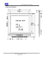
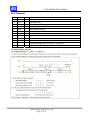
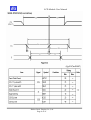
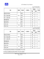
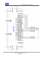
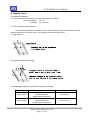
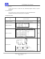
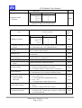
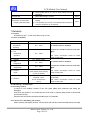
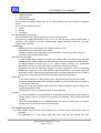
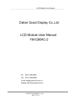
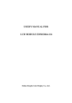
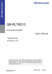
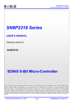
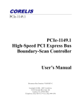
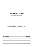
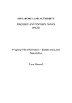
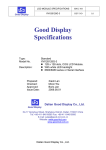
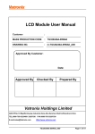
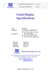
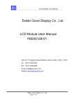
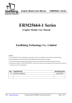
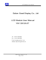
LCD Module User Manual Dalian Good Display Co., Ltd LCD Module User Manual YM 128128-07 Tel.: 86-411-84619565 Fax: 86-411-84619585 E-mail: sales @ good-lcd .com Website: http://www.good-lcd.com Dalian Good Display Co., Ltd Page 1 of 16 LCD Module User Manual REVISION RECORD REV. NO. DATA REVISION ITEMS 1.0 Decmber 20, 2007 First Release Version Dalian Good Display Co., Ltd Page 2 of 16 LCD Module User Manual Contents 1.Scope----------------------------------------------------------------------------4 2.Warranty------------------------------------------------------------------------4 3.Features-------------------------------------------------------------------------4 4.Mechanical Diagram---------------------------------------------------------6 5.I/O Terminal--------------------------------------------------------------------7 6. Quality Level-----------------------------------------------------------------13 7.Reliability---------------------------------------------------------------------17 8.Handling Precautions------------------------------------------------------17 9.Precautions for Use---------------------------------------------------------18 Dalian Good Display Co., Ltd Page 3 of 16 LCD Module User Manual 1.Scope This manual defines general provisions as well as inspection standards for standard LCD module. If the event of unforeseen problem or unspecified items may occur, please contact the nearest supplier or our company. 2.Warranty If module is not stored or used as specified in this manual, it will be void the 12- month warranty. 3.Features 3-1. Features (1) Display mode: Transflective type FSTN LCD (2) Display color: Display dots: Black Background:Grey (3) Display Fonts: Graphics Matrix (4)Input data: 3 SPI interfaced from a MPU (5) Multiplex ratio: 1/128 Duty, 1/12 Bias (6)Viewing direction: 6 O’clock (8) Controller: ST7541 3-2. Mechanical features Item Specifications Unit Outline dimensions 44.0(W)×51.0(H) ×2.0Max.(T) mm Viewing Area 41.0(W)×41.0(H) mm Image Area 35.82(W)×35.82(H) mm Number of Dots 128(W) ×128(H) mm Dot Size 0.26(W)×0.26(H) mm Dot Pitch 0.28(W)×0.28(H) mm Weight --- g 3-4.Absolute maximum ratings Item Symbol Condition Min Max Units Power supply for logic Vdd 25℃ 1.8 3.3 V Operating voltage for LCD V0 25℃ -- 15.0 V Operating temperature Top --- ﹣20 70 ℃ Storage temperature Tstg --- ﹣30 80 ℃ Dalian Good Display Co., Ltd Page 4 of 16 LCD Module User Manual Note: 1) The modules may be destroyed if they are used beyond absolute maximum ratings. In ordinary operation, it is desirable to use them within recommended operation conditions. Using the modules beyond these conditions may cause malfunction and poor reliability. 2) All voltage values are referenced to GND=0V. 3-4 Electrical characteristics (VDD=3.0V, Vss=0V,Ta = 25℃) Item Supply voltage for logic and for converter voltage Current consumption Symbol Condition Min. Typ. Max. Unit Vdd 25℃ - 3.0 3.3 V Idd 25℃ - 2.0 - mA Vih Vdd=3.0V 0.8Vdd --- Vdd Vil Vdd=3.0V Vss --- 0.2Vdd Input High Voltage Input Low Voltage Note: All the dots are in the static state. 3-5.Electro-Optic Characteristics NO Item Symbol Min Typ. Max Unit 1 Supply Voltage(Logic) Vdd-Vss -- 3.0 -- V 2 Supply Current (Logic) Idd -- 16.4 -- mA Vdd=3V -- 13.0 -- V -20℃ -- 12.6 -- V 25℃ -- 12.3 -- V 70℃ Ton -- 320 -- ms Toff -- 75 -- ms VLCD -- 11.4 -- V 3 4 5 LCD Driving Voltage Response Time LCD Operation Voltage Vout Dalian Good Display Co., Ltd Page 5 of 16 Condition 25℃ LCD Module User Manual 4. Mechanical Diagram Dalian Good Display Co., Ltd Page 6 of 16 LCD Module User Manual 5.I/O Terminal PIN Symbol I/O Description 1 CSB I Chip Select (active low) 2 RST II Rest (active low) 3 SCLK I Serial input clock (DB6) 4 SID I Serial input data (DB7) 5 VDD -- Power supply for logic 6 VSS -- Ground pin 7 VOUT -- Main LCD driving voltage input 8 V4 -- LCD driver voltage Tap4 (to 100 nF de-coupler) 9 V3 -- LCD driver voltage Tap3 (to 100 nF de-coupler) 10 V2 -- LCD driver voltage Tap2 (to 100 nF de-coupler) 11 V1 -- LCD driver voltage Tap1 (to 100 nF de-coupler) 12 V0 -- LCD driver voltage Tap0 (to 100 nF de-coupler) 5-2 Signal timing diagram Dalian Good Display Co., Ltd Page 7 of 16 LCD Module User Manual Dalian Good Display Co., Ltd Page 8 of 16 LCD Module User Manual Dalian Good Display Co., Ltd Page 9 of 16 LCD Module User Manual 5-3.Reference circuit examples Dalian Good Display Co., Ltd Page 10 of 16 LCD Module User Manual 6. Quality Level 6-1 Inspection conditions 6-1-1The environmental conditions for inspection shall be as follows: Room temperature: 20±3℃ Humidity: 65±20% RH 6-1-2 The external visual inspection: The inspection shall be performed by using a 20W fluorescent lamp for illumination and the distance between LCD and the eyes of the inspector should be at least 30cm. (1) Light method (2) Inspection distance and angle 6-2 Sampling procedures for each item’s acceptance level table Defect type Major defect Minor defect Sampling procedure MIL-STD-105D Inspection Level I Normal inspection Single sample inspection MIL-STD-105D Inspection Level I Normal inspection Single sample inspection Dalian Good Display Co., Ltd Page 11 of 16 AQL QC/07-2006(1) QC/07-2006(1) LCD Module User Manual 6-3 Classification of defects 6-3-1 Major defect A major defect refers to a defect that may substantially degrade usability for product applications. 6-3-2 Minor defect A minor defect refers to a defect that deviates from existing standards almost unrelated to the effective use of the product or its operation. 6-4 Inspection standar Item Criterion for defects Defect type 1) Display on inspection (1) Non display (2) Vertical line is deficient (3) Horizontal line is deficient (4) Cross line is deficient Size Φ(mm) Acceptable number Φ≤0.3 2) Black/White spot Major Ignore (note) 0.3<Φ≤0.45 3 0.45<Φ≤0.6 1 0.3<Φ 0 Minor (Note) Not allowed if four more spots crowd together Length (mm) L≤10 3) Black/White line Width (mm) Acceptable number W≤0.03 Ignore 5.0≤L≤10 0.03<W≤0.04 3 5.0≤L≤10 0.04<W≤0.05 2 1.0≤L≤10 0.05<W≤0.06 2 1.0≤L≤10 0.06<W≤0.08 L≤10 0.08<W Minor 1 follows 2) point defect Defects separate with each other at an interval of more than 20mm. 4) Display pattern Minor [Unit: mm] A+B≤0.45 2 0<C D+E≤0.35 F+G≤0.35 2 2 Note: 1) Up to 3 damages acceptable 2) Not allowed if there are two or more pinholes every 3 of Dalian Good Display Co., Ltd Page 12 of 16 LCD Module User Manual fourths inch. Size Φ(mm) Acceptable Number Φ≤0.7 Ignore (note) 0.7<Φ≤1.0 5) Spot-like contrast irregularity 3 1.0<Φ≤1.5 1 1.5<Φ 0 Minor Note: 1) Conformed to limit samples. 2)Intervals of defects are more than 30mm. Item Criterion for defects Defect type Size Φ(mm) Acceptable Number Φ≤0.4 6) Bubbles in polarizer 7) Scratches and dent on the polarizer 9) Rainbow color 10) Viewing area encroachment 11) Bezel appearance 12) Defect of land surface contact 2 0.65<Φ≤1.2 1 1.2<Φ 0 Scratches and dent on the polarizer shall be in the accordance with “2) Black/white spot”, and “3) Black/White line”. 8) Stains on the surface of LCD panel Ignore (note) 0.4<Φ≤0.65 Stains which cannot be removed even when wiped lightly with a soft cloth or similar cleaning. No rainbow color is allowed in the optimum contrast on state within the active area. Polarizer edge or line is visible in the opening viewing area due to polarizer shortness or sealing line. Minor Minor Minor Minor Minor Rust and deep damages that are visible in the bezel are rejected. Minor Evident crevices that are visible are rejected. Minor (1) Failure to mount parts 13) Parts mounting (2) Parts not in the specifications are mounted Major (3) For example: Polarity is reversed, HSC or TCP falls off. 14) Part alignment (1) LSI, IC lead width is more than 50% beyond pad outline. (2) More than 50% of LSI, IC leads is off the pad outline. Major (1) 0.45<Φ, N≥1 15) Conductive foreign matter (solder ball, solder hips) (2) 0.3<Φ≤0.45, Minor N≥1 Minor Φ: Average diameter of solder ball (unit: mm) (3) 0.5<L, N≥1 Minor L: Average length of solder chip (unit: mm) (1) Deep damage is found on copper foil and the pattern is nearly 16) PCB pattern damage Major broken. (2) Damage on copper foil other than 1) above Minor (1) Due to PCB copper foil pattern burnout, the pattern is 17) Faulty PCB correction connected, using a jumper wire for repair;2 or more places are corrected per PCB. Dalian Good Display Co., Ltd Page 13 of 16 Minor LCD Module User Manual (2) Short-circuited part is cut, and no resist coating has been performed. 18) Bezel flaw Bezel claw missing or not bent Minor (1) Failure to stamp or label error, or not legible.(all acceptable if 19) Indication on name plate (sampling indication label) legible) (2) The separation is more than 1/3 for indication discoloration, in Minor which the characters can be checked. 7.Reliability 7-1 Lifetime 50,000 hours (25℃ in the room without ray of sun) 7-2 Items of reliability Item Condition Criterion 1) High Temperature 60℃ 96hrs No cosmetic failure is allowable. Operating Contrast ratio should be between initial value ±10%. 2) Low Temperature -20℃ 96hrs Total current consumption should be below Operation double of initial value. 3) Humidity 4) 40℃, 90%RH, 96hrs High Temperature 5) Low Temperature 6) Thermal shock 70℃ 96hrs -30℃ 96hrs Contrast ratio should be between initial value ±20%. 25℃→30℃→25℃→70℃ 5(min) 30(min) 5(min) 30(min) 5 cycle, 55~60%RH 10~55~10hz 7) Vibration No cosmetic failure is allowable. amplitude: 1.5mm 2hrs for each direction (X,Y,Z) Total current consumption should be below double of initial value. No defects in cosmetic and operational function are allowable. Total current consumption should be below double of initial value. 8.Handling Precautions 8-1 Mounting method A panel of LCD module consists of two thin glass plates with polarizers that easily get damaged. And since the module in so constructed as to be fixed by utilizing fitting holes in the printed circuit board (PCB). Extreme care should be used when handling the LCD modules. 8-2 Cautions of LCD handling and cleaning When cleaning the display surface, use soft cloth with solvent (recommended below) and wipe Dalian Good Display Co., Ltd Page 14 of 16 LCD Module User Manual lightly. Isopropyl alcohol Ethyl alcohol Trichlorotriflorothane Do not wipe the display surface with dry or hard materials that will damage the polarizer surface. Do not use the following solvent: Water Ketone Aromatics 8-3 Caution against static charge The LCD module use C-MOS LSI drivers. So we recommend you: Connect any unused input terminal to Vdd or Vss. Do not input any signals before power is turned on, and ground your body, work/assembly areas, assembly equipment to protect against static electricity. 8-4 Packaging - Module employs LCD elements, and must be treated as such. Avoid intense shock and falls from a height. To prevent modules from degradation, do not operate or store them exposed direct to sunshine or high temperature/humidity. 8-5 Caution for operation - It is an indispensable condition to drive LCD module within the limits of the specified voltage since the higher voltage over the limits may cause the shorter life of LCD module. An electrochemical reaction due to DC (direct current) causes LCD undesirable deterioration so that the uses of DC (direct current) drive should be avoided. - Response time will be extremely delayed at lower temperature than the operating temperature range and on the other hand at higher temperature LCD module may show dark color in them. However those phenomena do not mean malfunction or out of order of LCD module, which will come back in the specified operating temperature. 8-6 Storage In the case of storing for a long period of time, the following ways are recommended: - Storage in polyethylene bag with the opening sealed so as not to enter fresh air outside in it. And with not desiccant. - Placing in a dark place where neither exposure to direct sunlight nor light is. Keeping the storage temperature range. - Storing with no touch on polarizer surface by any thing else. 8-7 Safety - It is recommendable to crash damaged or unnecessary LCD into pieces and to wash off liquid crystal by either of solvents such as acetone and ethanol, which should be burned up later. - When any liquid leaked out of a damaged glass cell comes in contact with your hands, please wash it off well at once with soap and water. 9.Precautions for Use 9-1 Both parties should provide a limit sample on an occasion when both parties agree its necessity. The judgement by a limit sample shall take effect after the limit sample has been Dalian Good Display Co., Ltd Page 15 of 16 LCD Module User Manual established and confirmed by both parties 9-2 On the following occasions, the handling of problem should be decided through discussion and agreement between responsible of the both parties. -When a question is arisen in this manual. -When a new problem is arisen which is not specified in this manual. -Some problem is arisen due to the change of inspection and operating conditions in users. -When a new problem is arisen at the customer’s operating set for sample evaluation in the customer site. Dalian Good Display Co., Ltd Page 16 of 16