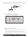
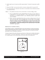
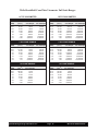
1
BROOKFIELD DIAL VISCOMETER Operating Instructions Manual No. M/85-150-P700 Please record the Model and Serial Number of your viscometer. Having this information readily available will help us to assist you should there be any questions regarding your instrument. Model No. _____________________ Serial No. _____________________ SPECIALISTS IN THE MEASUREMENT AND CONTROL OF VISCOSITY BROOKFIELD ENGINEERING LABORATORIES, INC. 11 Commerce Boulevard, Middleboro, MA 02346-1031 USA TEL 508-946-6200 or 800-628-8139 F AX 508-946-6262 www.brookfieldengineering.com Brookfield Engineering Laboratories, Inc. Page 1 Manual No. M/85-150-P700 TABLE OF CONTENTS I. INTRODUCTION ................................................................................ 3 I.1 I.2 I.3 I.4 II. Components .................................................................................... 3 Utilities ........................................................................................... 4 Specifications ................................................................................. 4 Set-Up ............................................................................................. 4 GETTING STARTED .......................................................................... 5 II.1 II.2 II.3 Operation ........................................................................................ 5 Viscometer Readings and Viscosity Calculations.......................... 5 Considerations for Making Measurements ..................................... 8 APPENDIX A APPENDIX B APPENDIX C APPENDIX D APPENDIX E - Cone/Plate Viscometer Set-Up ........................................ 9 Viscosity Ranges ........................................................... 18 Variables in Viscosity Measurements............................ 20 Calibration Procedures .................................................. 22 Models A & A-E Laboratory Stands with Parts Identification ........................................... 29 APPENDIX F - Fault Diagnosis and Troubleshooting ........................... 31 APPENDIX G - Warranty Repair and Service ........................................ 33 Tear-off Sheet - Viscosity Test Report .................................................... 35 Brookfield Engineering Laboratories, Inc. Page 2 Manual No. M/85-150-P700 I. INTRODUCTION The Brookfield Dial Viscometer measures fluid viscosity at given shear rates. Viscosity is a measure of a fluid’s resistance to flow. You will find a detailed description of the mathematics of viscosity in the Brookfield publication “More Solutions to Sticky Problems” a copy of which was included with your Dial Viscometer. The Dial Viscometer rotates a sensing element in a fluid and measures the torque necessary to overcome the viscous resistance to the induced movement. This is accomplished by driving the immersed element, which is called a spindle, through a beryllium copper spring. The degree to which the spring is wound, indicated by the red pointer, is proportional to the viscosity of the fluid. The Viscometer is able to measure over a number of ranges since, for a given spring deflection, the actual viscosity is proportional to the spindle speed and is related to the spindle's size and shape. For a material of given viscosity, the resistance will be greater as the spindle size and/or rotational speed increase. The minimum viscosity range is obtained by using the largest spindle at the highest speed; the maximum range by using the smallest spindle at the slowest speed. There are four basic spring torque series offered by Brookfield: Model LV RV HA HB Spring Torque (Dyne-cm) 673.7 7,187.0 14,374.0 57,496.0 The higher the torque calibration, the higher the measurement range. The viscosity measurement range for each torque calibration may be found in Appendix B. All units of measurement are calculated in units of centipoise (cP) by using a look-up table known as "the Brookfield Factor Finder" to convert torque reading. The equivalent units of measurement in the SI system are calculated using the following conversions: Viscosity: Torque: CGS 1 cP 107 dyne-cm = = SI 1 mPa•s 1 Newton-m mPa•s = milli Pascal - second I.1 Components 1) 2) 3) 4) 5) 6) 7) Dial Viscometer Model A Laboratory Stand Spindle Set with Case (4 spindles for LVF, LVT; 7 Spindles for RVF, RVT, HAT, and HBT). For Cone/Plate versions: a spindle wrench, one cone spindle and a sample cup (Part No. CP-44Y) replace the spindle set Guard Leg (LVF, LVT, RVF, and RVT only) Carrying Case Operating Instruction Manual Factor Finder Please check to be sure that you have received all components, and that there is no damage. If you are missing any parts, please notify Brookfield Engineering or your local Brookfield agent immediately. Any shipping damage must be reported to the carrier. Brookfield Engineering Laboratories, Inc. Page 3 Manual No. M/85-150-P700 I.2 Utilities Input Voltage: Input Frequency: Power Consumption: 115 VAC or 230 VAC 50 or 60 Hz Less than 20 WATTS I.3 Specifications Speeds: LVF: LVT: 60, 30, 12, 6 60, 30, 12, 6, 3, 1.5, 0.6, 0.3 RVF: RVT: 20, 10, 4, 2 100, 50, 20, 10, 5, 2.5, 1, 0.5 HAT: HBT: 100, 50, 20, 10, 5, 2.5, 1, 0.5 100, 50, 20, 10, 5, 2.5, 1, 0.5 Accuracy: ± 1% of Full Scale Range in use (See Appendix D for details) Repeatability: ± 0.2% of Full Scale Range in use Weight: Operating Temperature: Gross Weight Net Weight Carton Volume 20 lb 17 lb 1.65 cu ft 9 kg 7.7 kg 0.05 m3 -20°C (-4°F) to 65°C (149°F) I.4 Set-Up 1) Assemble the laboratory stand. (Refer to Appendix E.) 2) Mount the Viscometer securely on a Brookfield laboratory stand. On some Viscometers, it may be necessary to unscrew the nut located at the point where the power cord enters the viscometer. This permits the metal handle to be inserted into the laboratory stand clamp. Note: The position of the laboratory stand clamp assembly is important. Refer to Appendix E for proper alignment and positioning of the clamp assembly. Level the viscometer, referring to the bubble level on the instrument. If the viscometer cannot be leveled, recheck the laboratory stand assembly, as shown on Sheet #82-0330 (supplied with Model A laboratory stand). 3) Verify that the viscometer's power requirements match your power source before connecting it to power. 4) For Cone/Plate models, refer to Appendix A. Brookfield Engineering Laboratories, Inc. Page 4 Manual No. M/85-150-P700 II. GETTING STARTED II.1 Operation The Brookfield Viscometer is powered by a precision synchronous motor. Exact speeds of rotation are assured as the motor will turn erratically and spasmodically if synchronization cannot be maintained. Speed changes are affected by a gear train having either four or eight speeds. Maximum speed (RPM) will be set at full clockwise rotation and minimum speed at full counter-clockwise rotation. Although not absolutely necessary, it is advisable to change speeds while the motor is running. Four speed Viscometers have a square speed control knob with one number shown on each of four faces. The instrument’s rotational speed is indicated by the number facing up. Eight speed models have a square speed control knob with two numbers on each face; by moving the knob through two complete turns, speeds may be changed in sequence. No trouble will be experienced in differentiating between the two speeds shown on each face since each pair is in the ratio of 20:1. To insure rotation at the indicated speed, it is important that the face of the knob upon which this speed is shown be closely parallel to the viscometer’s dial. LV Viscometers are provided with a set of four spindles and a narrow guard leg; RV Viscometers come with a set of seven spindles and a wider guard leg; HA and HB Viscometers come with a set of seven spindles and no guard leg. The spindles are attached to the viscometer by screwing them to the lower shaft. Note that the spindles have a left-hand thread. The lower shaft should be held in one hand and lifted up. The spindle should be screwed to the left. The face of the spindle nut and the matching surface on the lower shaft should be smooth and clean to prevent eccentric rotation of the spindle. Spindles can be identified by the number on the side of the spindle nut. All Brookfield Dial Reading Viscometers are provided with a clutch lever located at the back of the instrument. Depressing the lever raises the dial against the pointer and “holds” the instrument’s reading. When the clutch is released the dial is lowered and the pointer will be freed. Any of the controls on the Viscometer - the motor switch, speed change knob, and clutch - may be operated independently of the other. II.2 Viscometer Readings and Viscosity Calculations 1. Mount the guard leg, if used, (spindle protector) on the viscometer. 2. Attach the spindle (left-hand thread) to the viscometer lower shaft by lifting the coupling screw slightly. Hold it firmly with one hand while screwing the spindle on with the other (note left-hand thread). Avoid putting side thrust on the shaft. To avoid trapping air bubbles under the disc-type spindles, do the following before attaching the spindle. Begin by immersing the spindle in a diagonal path, slowly drag the spindle across the Brookfield Engineering Laboratories, Inc. Page 5 Manual No. M/85-150-P700 fluid surface, and bring the spindle to an upright position and thread onto screw. 3. Lower and center spindle in the test material (600 ml beaker) until the "meniscus" of the fluid is at the center of the immersion groove on the spindle’s shaft. 4. To make a viscosity measurement, turn the motor switch “ON”. This energizes the viscometer drive motor. Allow time for the indicated reading to stabilize. The time required for stabilization will depend on the speed at which the viscometer is running and the characteristics of the sample fluid. When making a viscosity measurement, the reading should be noted and multiplied by the factor appropriate to the viscometer model/spindle/speed combination being used. Refer to the table below or to the FACTOR FINDER for calculating viscosity. For maximum accuracy, readings below 10.0% torque (dial reading) should be avoided. 5. Turn the viscometer motor switch “OFF” when changing a spindle, changing samples, etc. Remove spindle before cleaning. 6. The interpretation of results and the instrument’s use with non-Newtonian and thixotropic materials is discussed in the booklet, “More Solutions to Sticky Problems” and in Appendix C. The following tables apply to Brookfield Viscometer Models LV, RV, HA and HB with standard spindles. They enable the user to convert the percent scale reading into a viscosity value in units of centipoise. To convert the viscometer dial reading to a viscosity value in units of centipoise, multiply the reading noted on dial viscometer by the appropriate factor in the following tables. LV Series Viscometer 1 2 3 4 .3 200 .3 1K .3 4K .3 20K .6 100 .6 500 .6 2K .6 10K 1.5 40 1.5 200 1.5 800 1.5 4K 3 20 3 100 3 400 3 2K 6 10 6 50 6 200 6 1K 12 5 12 25 12 100 12 500 30 2 30 10 30 40 30 200 60 1 60 5 60 20 60 100 = Spindle = Factor Brookfield Engineering Laboratories, Inc. = Spindle Speed K = 1000 Page 6 Manual No. M/85-150-P700 RV Series Viscometer 1 2 .5 200 1 100 2 50 2.5 40 4 25 5 20 10 10 20 5 50 2 100 1 .5 1 2 2.5 4 5 10 20 50 100 800 400 200 160 100 80 40 20 8 4 3 .5 1 2 2.5 4 5 10 20 50 100 2K 1K 500 400 250 200 100 50 20 10 4 .5 1 2 2.5 4 5 10 20 50 100 5 4K 2K 1K 800 500 400 200 100 40 20 .5 1 2 2.5 4 5 10 20 50 100 6 8K 4K 2K 1.6K 1K 800 400 200 80 40 = Spindle Speed = Spindle .5 1 2 2.5 4 5 10 20 50 100 7 20K 10K 5K 4K 2.5K 2K 1K 500 200 100 .5 1 2 2.5 4 5 10 20 50 100 80K 40K 20K 16K 10K 8K 4K 2K 800 400 K = 1000 = Factor HA Series Viscometer 1 2 .5 400 .5 1 200 1 2 100 2 2.5 80 2.5 5 40 5 10 20 10 20 10 20 50 4 50 100 2 100 3 1.6K .5 800 1 400 2 320 2.5 160 5 80 10 40 20 16 50 8 100 = Spindle 4K 2K 1K 800 400 200 100 40 20 4 .5 1 2 2.5 5 10 20 50 100 5 8K 4K 2K 1.6K 800 400 200 80 40 .5 1 2 2.5 5 10 20 50 100 6 16K 8K 4K 3.2K 1.6K 800 400 160 80 = Spindle Speed .5 1 2 2.5 5 10 20 50 100 7 40K 20K 10K 8K 4K 2K 1K 400 200 .5 1 2 2.5 5 10 20 50 100 160K 80K 40K 32K 16K 8K 4K 1.6K 800 K = 1000 = Factor HB Series Viscometer 1 2 .5 1.6K 1 800 2 400 2.5 320 5 160 10 80 20 40 50 16 100 8 3 .5 6.4K .5 16K 1 3.2K 1 8K 2 1.6K 2 4K 2.5 1.28K 2.5 3.2K 5 640 5 1.6K 10 320 10 800 20 160 20 400 50 64 50 160 100 32 100 80 = Spindle 4 5 6 .5 32K .5 64K 1 16K 1 32K 2 8K 2 16K 2.5 6.4K 2.5 12.8K 5 3.2K 5 6.4K 10 1.63K 10 3.2K 20 800 20 1.6K 50 320 50 640 100 160 100 320 = Spindle Speed 7 .5 160K 1 80K 2 40K 2.5 32K 5 16K 10 8K 20 4K 50 1.6K 100 800 = Factor .5 1 2 2.5 5 10 20 50 100 640K 320K 160K 128K 64K 32K 16K 6.4K 3.2K K = 1000 Dial reading x Factor = Viscosity in cP (mPa•s) Example: LVT Viscometer with #1 spindle at 6 rpm Dial Reading: 75 Factor: 10 75 x 10 = 750 cP (mPa•s) Full scale viscosity range for any speed and spindle combination is equal to the factor x 100. Factor x 100 = Full scale range Example: LVT Viscometer with #1 spindle at 6 RPM Full Scale Range: 10 x 100 = 1,000 cP Brookfield Engineering Laboratories, Inc. Page 7 Manual No. M/85-150-P700 II.3 Considerations for Making Measurements In taking viscosity measurements with the Dial Viscometer there are two considerations which pertain to the low viscosity limit of effective measurement. 1) Viscosity measurements should be accepted within the equivalent % Torque Range from 10% to 100% for any combination of spindle/speed rotation. 2) Viscosity measurements should be taken under laminar flow conditions, not under turbulent flow conditions. The first consideration has to do with the precision of the instrument. All Dial Viscometers have a full scale range precision of ± 1% for any spindle/speed combination. We discourage taking readings below 10% of range because the potential viscosity error of ± 1% is a relatively high number compared to the instrument reading. The second consideration involves the mechanics of fluid flow. All rheological measurements of fluid flow properties should be made under laminar flow conditions. Laminar flow is flow wherein all particle movement is in layers directed by the shearing force. For rotational systems, this means all fluid movement must be circumferential. When the inertial forces on the fluid become too great, the fluid can break into turbulent flow wherein the movement of fluid particles becomes random and the flow can not be analyzed with standard math models. This turbulence creates a falsely high viscometer reading with the degree of non-linear increase in reading being directly related to the degree of turbulence in the fluid. For the following geometries, we have found that an approximate transition point to turbulent flow occurs as follows: 1) No. 1 LV Spindle: 2) No. 1 RV Spindle: 3) UL Adapter: 15 cP at 60 RPM 100 cP at 50 RPM 0.85 cP at 60 RPM Turbulent conditions will exist in these situations whenever the RPM/cP ratio exceeds the values listed above. Brookfield Engineering Laboratories, Inc. Page 8 Manual No. M/85-150-P700 APPENDIX A - Cone/Plate Viscometer Set-Up The Wells-Brookfield Dial Viscometer uses the same operating instruction procedures as described in this manual, however, the gap between the cone and the plate must be mechanically adjusted before measurements are made. This is done by moving the plate (built into the sample cup, Part No. CP-44Y) up towards the cone until two small pins (one in the cone, the second mounted on the plate) contact slightly, and then by separating (lowering) the plate 0.0005inch (0.013mm). Note that the Wells-BrookfieldCone/Plate Viscometer requires the use of a circulating temperature bath controlling temperature to within +/- 0.1 °C. The bath is connected to the ports on the CP-44Y sample cup. Brookfield offers a complete line of refrigerated and non-refrigerated (tap water cooling) circulating water baths. The following example assumes that the C/P Viscometer is set up on the Model A laboratory stand and has been leveled. Cone CP-40 is used in the illustrations. The water bath is on, set at the same test temperature that you will use when measuring the viscosity of your sample and is connected to the sample cup (Figure A1). Allow enough time for the bath to reach the test temperature. The Viscometer speed knob should be set at 10 or 12 rpm with motor OFF. Adjustment Ring Cup Outlet Bath Outlet Bath Inlet PUMP OUTLET PUMP INLET Water Bath Cup Inlet Sample Cup Figure A1 Brookfield Engineering Laboratories, Inc. Page 9 Manual No. M/85-150-P700 Remove the sample cup and attach the cone to the Viscometer (Note: left hand threads), using the spindle wrench to hold the Viscometer shaft (Figure A2). Note: Lift up gently on the spindle wrench. These surfaes must be clean! Spindle Wrench Cone Figure A2 Attach the sample cup and swing the clip under the cup to secure it in place. Take care to avoid hitting the cone with the cup (Figure A3). Note: Do not add test sample during the gap setting procedure. Do Not Hit the CONE with the CUP! Figure A3 Start the Viscometer running at 10 or 12 rpm. Readings of % Torque (dial reading) will be utilized for setting the cone/plate gap. If the display reading jumps to 0.5% of scale (or higher), or will not settle to zero (indicating that the pins on the cone and cup are hitting), unscrew the adjustment ring by turning it to the left (clockwise as you look down on the instrument) until the reading settles at 0.0% (Figure A4). Brookfield Engineering Laboratories, Inc. Page 10 Manual No. M/85-150-P700 Index Mark Adjustment Ring Turn Adjusting Ring clockwise until the % torque display is stable at 0.0% Figure A4 Turn the adjustment ring to the right (counterclockwise as you look down on the instrument) in small increments (one or two divisions of the ring) while watching the Viscometer dial (Figure A5). Remember that you are trying to raise the cup so that the pin in the cone touches the pin in the cup. Once you have found this hit point, you can "back off" to create the desired gap between cone and cup. You must wait at least 6 seconds between movements of the ring. Turn the adjustment ring until the display reading jumps from 0.0 to 0.5% (HA and HB models) or from 0.0 to 0.5 % (RV models) or 0.0 to 1.0% (LV models). This is the HIT POINT. The cup may have to be adjusted up and down several times before this deflection is satisfactorily reached. The LV series Viscometer will be the most sensitive. Index Mark Adjustment Ring Turn Adjustment Ring Counterclockwise in Small Increments Figure A5 Brookfield Engineering Laboratories, Inc. Page 11 Manual No. M/85-150-P700 When you are satisfied the pins are just hitting (by observing acceptable % readings), make a pencil mark on the adjustment ring directly under the index mark on the pivot housing (Figure A6). Index Mark Adjustment Ring Make a pencil mark directly under the index mark Figure A6 Turn the adjustment ring to the left (clockwise as you look down on the instrument) exactly the width of one division from the pencil mark you have just made. This will separate the pins by 0.0005" (0.013 mm). This is a very important step because if it is not done, the pins may touch constantly and may cause wear and damage to the cone, cup and instrument. The Viscometer is now mechanically set and ready for sample measurement (Figure A7). Index Mark Adjustment Ring with Index Mark (enlarged) Adjustment Ring One Scale Division Turn Adjustment Ring Clockwise a Distance Equal to One Scale Division Figure A7 Brookfield Engineering Laboratories, Inc. Page 12 Manual No. M/85-150-P700 Each of the five available cones has a specific sample volume, as shown in Table A1. Note that the correct amount of sample fluid should cover the cone face and up over the edge less than 1mm as shown in (Figure A8). Less than 1 mm Cone Sample Cup Figure A8 Notes: a) The cup may be removed without resetting the gap. b) Remove the spindle from the viscometer when you clean it. c) Find the hit point every time the spindle is attached. Table A1 Cone Sample Volume CP-40 CP-41 CP-42 CP-51 CP-52 0.5 ml 2.0 ml 1.0 ml 0.5 ml 0.5 ml Cone Angle 0.8° 3.0° 1.565° 1.565° 3.0° Calibration Procedure using Cone/Plate Viscometer 1) Ensure that the circulating bath used maintains the stated calibration temperature to within ± 0.1°C. 2) The attachment of the cone spindle and sample cup, and the gap setting between the cone and cup must be accomplished by following "Cone/Plate Rheometer Set Up" Procedure. 3) Put the proper amount of viscosity standard fluid into the sample cup. The amount varies per cone spindle (refer to Table A1). Brookfield Engineering Laboratories, Inc. Page 13 Manual No. M/85-150-P700 4) Attach sample cup to viscometer and allow approximately 15 minutes for temperature equilibrium. 5) Measure the fluid's viscosity and record the viscometer readings (both % torque and cP). 6) See "Interpretation of Test Results" shown below for calculation of total calibration tolerance (instrument and fluid). Notes: 1) The spindle must rotate at least (5) times before a viscosity reading is taken. 2) The use of Brookfield Viscosity Standard fluids in the range of 5 cP to 5000 cP is recommended for cone/plate instruments. Please contact Brookfield Engineering Laboratories or an authorized dealer if your calibration procedure requires more viscous standards. 3) Select a viscosity standard fluid that will give viscosity readings between 10% and 100% of full scale range. Refer to Appendix B for viscosity ranges of cone spindles. Do not use a silicone viscosity standard fluid with a viscosity value greater than 5000 cP with a Cone/Plate Viscometer. Brookfield offers a complete range of mineral oil viscosity standards suitable for use with Cone/Plate Viscometers as shown in Table D2 (Appendix D). Consult with Brookfield or an authorized dealer to determine which fluid is appropriate. Mathematics of Cone/Plate Geometry Cone and Plate geometry, as illustrated in Figure A9, is the fixation of a conical vertex perpendicular to and in point contact with a flat plate. When the cone is made very obtuse (θ less than 4°) and rotated at constant speed (ω), precise viscosity measurements are obtained at absolute and uniform values of shearing rate and stress. Viscosity (in poise) is the ratio of shear stress to shear rate. Shear stress is related to the summation of torque ( T ) over the conical surface. Shear rate is related to the cone rotational speed (ω), and gap width (c) at any radial distance (r) from the center of the rotating cone. ω Cone Plate c θ r ω Figure A9 Brookfield Engineering Laboratories, Inc. Page 14 Manual No. M/85-150-P700 The ratio of (ωr) and (c) is a constant for any value of (r). Since (c) is a maximum at cone radius (r), the shear rate is related to (ω) and sin θ. For the Wells-Brookfield Cone/Plate Viscometer, the mathematical relationships are: Shear Stress (dynes/cm2) = T 2/3 π r3 ω Shear Rate (sec-1) = Sin θ Viscosity (centipoise or mPa•s) = Shear Stress x 100 Shear Rate where: T = r = ω = θ = % Full Scale Torque (dyne-cm) Cone Radius (cm) Cone Speed (rad/sec) Cone Angle (degrees) Cone Spindle Angle (deg.) Radius (cm) CP-40 or CPE-40 CP-41 or CPE-41 CP-42 or CPE-42 CP-51 or CPE-51 CP-52 or CPE-52 0.8 3.0 1.565 1.565 3.0 2.4 2.4 2.4 1.2 1.2 Viscometer Model Series Spring Torque (Dyne-Centimeter) LV RV HA HB 673.7 7,187.0 14,374.0 57,496.0 Brookfield Engineering Laboratories, Inc. Page 15 Manual No. M/85-150-P700 Wells-Brookfield Cone/Plate Viscometer Full Scale Ranges LVTCP VISCOMETER RVTCP VISCOMETER 3.0° CONE SPINDLE Speed (RPM) 60.0 30.0 12.0 6.0 3.0 1.5 0.6 0.3 Shear Rate (sec-1) 120.00 60.00 24.00 12.00 6.00 3.00 1.20 0.60 Speed (RPM) 60.0 30.0 12.0 6.0 3.0 1.5 0.6 0.3 Shear Rate (sec-1) 230.00 115.00 46.00 23.00 11.50 5.75 2.30 1.15 Cone #CP-41 2 ml Sample 19.20 38.40 96.00 192.00 384.00 768.00 1,920.00 3,840.00 3.0° CONE SPINDLE Cone #CP-52 0.5 ml Sample 155.33 310.66 776.64 1,553.30 3,106.60 6,213.10 15,532.80 31,065.60 Speed (RPM) 100.0 50.0 20.0 10.0 5.0 2.5 1.0 0.5 Shear Rate (sec-1) 200.00 100.00 40.00 20.00 10.00 5.00 2.00 1.00 Cone #CP-51 0.5 ml Sample 80.90 161.80 404.50 809.00 1,618.00 3,236.00 8,090.00 16,180.00 Speed (RPM) 100.0 50.0 20.0 10.0 5.0 2.5 1.0 0.5 Shear Rate (sec-1) 384.00 192.00 76.80 38.40 19.20 9.60 3.84 1.92 1.565° CONE SPINDLE Cone #CP-42 1 ml Sample 10.00 20.00 50.00 100.00 200.00 400.00 1,000.00 2,000.00 Shear Rate (sec-1) 450.00 225.00 90.00 45.00 22.50 11.25 4.50 2.25 Cone #CP-52 0.5 ml Sample 983.00 1,966.00 4,915.00 9,830.00 19,660.00 39,320.00 98,300.00 196,600.00 1.565° CONE SPINDLE 0.8° CONE SPINDLE Speed (RPM) 60.0 30.0 12.0 6.0 3.0 1.5 0.6 0.3 Cone #CP-41 2 ml Sample 122.88 245.76 614.40 1,228.80 2,457.60 4,915.20 12,288.00 24,576.00 Cone #CP-40 0.5 ml Sample 5.14 10.28 25.70 51.40 102.80 205.60 514.00 1,028.00 Brookfield Engineering Laboratories, Inc. Cone #CP-42 1 ml Sample 64.00 128.00 320.00 6,400.00 1,280.00 2,560.00 6,400.00 12,800.00 Cone #CP-51 0.5 ml Sample 512.00 1,024.00 2,560.00 5,120.00 10,240.00 20,480.00 51,200.00 102,400.00 0.8° CONE SPINDLE Speed (RPM) 100.0 50.0 20.0 10.0 5.0 2.5 1.0 0.5 Page 16 Shear Rate (sec-1) 750.00 375.00 150.00 75.00 37.50 18.75 7.50 3.75 Cone #CP-40 0.5 ml Sample 32.70 65.40 163.50 327.00 654.00 1,308.00 3,270.00 6,540.00 Manual No. M/85-150-P700 Wells-Brookfield Cone/Plate Viscometer Full Scale Ranges HATCP VISCOMETER HBTCP VISCOMETER 3.0° CONE SPINDLE Speed (RPM) 100.0 50.0 20.0 10.0 5.0 2.5 1.0 0.5 Shear Rate (sec-1) 200.00 100.00 40.00 20.00 10.00 5.00 2.00 1.00 Cone #CP-41 2 ml Sample 245.76 491.52 1,228.80 2,457.60 4,915.20 9,830.40 24,576.00 49,152.00 3.0° CONE SPINDLE Cone #CP-52 0.5 ml Sample 1,966.00 3,932.00 9,830.00 19,660.00 39,320.00 78,640.00 196,600.00 393,200.00 Speed (RPM) 100.0 50.0 20.0 10.0 5.0 2.5 1.0 0.5 1.565° CONE SPINDLE Speed (RPM) 100.0 50.0 20.0 10.0 5.0 2.5 1.0 0.5 Shear Rate (sec-1) 384.00 192.00 76.80 38.40 19.20 9.60 3.84 1.92 Speed (RPM) 100.0 50.0 20.0 10.0 5.0 2.5 1.0 0.5 Shear Rate (sec-1) 750.00 375.00 150.00 75.00 37.50 18.75 7.50 3.75 Cone #CP-42 1 ml Sample 128.00 256.00 640.00 1,280.00 2,560.00 5,120.00 12,800.00 25,600.00 Shear Rate (sec-1) 200.00 100.00 40.00 20.00 10.00 5.00 2.00 1.00 Cone #CP-41 Cone #CP-52 2 ml Sample 0.5 ml Sample 983.00 7,864.00 1,966.00 15,728.00 4,915.00 39,320.00 9,830.00 78,640.00 19,660.00 157,280.00 39,320.00 314,560.00 98,300.00 786,400.00 196,600.00 1,572,800.00 1.565° CONE SPINDLE Cone #CP-51 0.5 ml Sample 1,024.00 2,048.00 5,120.00 10,240.00 20,480.00 40,960.00 102,400.00 204,800.00 Speed (RPM) 100.0 50.0 20.0 10.0 5.0 2.5 1.0 0.5 Shear Rate (sec-1) Speed (RPM) 100.0 50.0 20.0 10.0 5.0 2.5 1.0 0.5 Shear Rate (sec-1) 750.00 375.00 150.00 75.00 37.50 18.75 7.50 3.75 0.8° CONE SPINDLE 384.00 192.00 76.80 38.40 19.20 9.60 3.84 1.92 Cone #CP-42 1 ml Sample 512.00 1,024.00 2,560.00 5,120.00 10,240.00 20,480.00 51,200.00 102,400.00 Cone #CP-51 0.5 ml Sample 4,096.00 8,192.00 20,480.00 40,960.00 81,920.00 163,840.00 409,600.00 819,200.00 0.8° CONE SPINDLE Cone #CP-40 0.5 ml Sample 65.40 130.80 327.00 654.00 1,308.00 2,616.00 6,540.00 13,080.00 Cone #CP-40 0.5 ml Sample 262.00 524.00 1,310.00 2,620.00 5,240.00 10,480.00 26,200.00 52,400.00 Viscometer Ranges in Centipoise (1 cP = 1 mPa•s) Viscosity = Dial Reading x Factor Factor = Viscometer Range/100 Note: When calibrating 2.4cm diameter cone spindles CP-51 or CP-52 at shear rates greater than 384 sec-1, use Brookfield Viscosity Standards 5,000 cP or lower. Brookfield Engineering Laboratories, Inc. Page 17 Manual No. M/85-150-P700 APPENDIX B - Viscosity Ranges LV Series Viscometers with Spindles #1 - #4 RV/HA/HB Series Viscometers with Spindles #1 - #7 Viscosity Range (cP) Viscometer Minimum LVF LVT RVF RVT HAT HBT 15 15 100 100 200 800 Maximum 100,000 2,000,000 2,000,000 8,000,000 16,000,000 64,000,000 Small Sample Adapter and Thermosel Viscosity (cP) SSA & T-Sel Spindle 16 18 25 31 34 SSA & T-Sel Spindle 14 15 21 27 28 29 Shear Rate (1/SEC) 0.29N 1.32N 0.22N 0.34N 0.28N 200 5 800 50 100 SSA & T-Sel Spindle Shear Rate (1/SEC) 14 15 21 27 28 29 0.40N 0.48N 0.93N 0.34N 0.28N 0.25N 200 5 800 50 100 LVT 400,000 10,000 - 1,600,000 100,000 200,000 Viscosity (cP) Shear Rate (1/SEC) 0.40N 0.48N 0.93N 0.34N 0.28N 0.25N LVF - 20,000 500 - 80,000 5,000 - 10,000 RVF 6,250 2,500 250 1,250 2,500 5,000 - RVT 625,000 250,000 25,000 125,000 250,000 500,000 1,250 500 50 250 500 1,000 - 2,500,000 1,000,000 100,000 500,000 1,000,000 2,000,000 Viscosity (cP) 2,500 1,000 100 500 1,000 2,000 HAT HBT - - 20,000,000 - 8,000,000 800,000 - 4,000,000 - 8,000,000 - 16,000,000 5,000,000 10,000 2,000,000 4,000 200,000 400 1,000,000 2,000 2,000,000 4,000 4,000,000 8,000 N = RPM Brookfield Engineering Laboratories, Inc. Page 18 Manual No. M/85-150-P700 UL Adapter UL Spindle Viscosity (cP) Shear Rate (1/SEC) YULA-15 or 15Z ULA-DIN-Y 1.22N 1.29N LVT RVT HAT HBT 1.0 - 2,000 6.4 - 2,000 12.8 - 2,000 51.2 - 2,000 1.9 - 3,812 12.2 - 5,000 24.4 - 5,000 97.6 - 5,000 N = RPM Cone/Plate Viscometer Viscosity (cP) Cone Shear Rate Spindle (1/SEC) LVTC/P RVTC/P HATC/P HBTC/P CP-40 7.5N 0.5 - 1,028 3.3 - 6,540 6.6 - 13,080 26.2 52,400 CP-41 2.0N 1.9 - 3,840 12.3 - 24,576 24.6 - 49,152 98.4 - 196,600 CP-42 3.84N 1.0 - 2,000 6.4 - 12,800 12.8 - 25,600 51.2 - 102,400 CP-51 3.84N 8.1 - 16,180 51.2 - 102,400 102.4 - 204,800 409.6 - 819,200 CP-52 2.0N 15.5 - 31,065 98.3 - 196,600 196.6 - 393,200 786.4 - 1,572,800 N = RPM Helipath with T-Bar Spindles T-Bar Spindle T-A T-B T-C T-D T-E T-F T-Bar Spindle T-A T-B T-C T-D T-E T-F Viscosity (cP) 156 312 780 1,560 3,900 7,800 156 312 780 1,560 3,900 7,800 LVT 62,400 124,800 312,000 624,000 - 1,560,000 - 3,120,000 Viscosity (cP) 2,000 4,000 10,000 20,000 50,000 100,000 RVF 100,000 2,000 200,000 4,000 500,000 10,000 - 1,000,000 20,000 - 2,500,000 50,000 - 5,000,000 100,000 RVT 400,000 800,000 2,000,000 4,000,000 - 10,000,000 - 20,000,000 Viscosity (cP) T-Bar Spindle T-A T-B T-C T-D T-E T-F LVF 3,120 6,240 - 15,600 - 31,200 - 78,000 - 156,000 4,000 8,000 20,000 40,000 100,000 200,000 Brookfield Engineering Laboratories, Inc. HAT HBT 800,000 16,000 - 1,600,000 32,000 - 4,000,000 80,000 - 8,000,000 160,000 - 20,000,000 400,000 - 40,000,000 800,000 3,200,000 6,400,000 - 16,000,000 - 32,000,000 - 80,000,000 - 160,000,000 Page 19 Manual No. M/85-150-P700 APPENDIX C - Variables in Viscosity Measurements As with any instrument measurement, there are variables that can affect a viscometer measurement. These variables may be related to the instrument (viscometer), or the test fluid. Variables related to the test fluid deal with the rheological properties of the fluid, while instrument variables would include the viscometer design and the spindle geometry system utilized. Rheological Properties Fluids have different rheological characteristics that can be described by viscometer measurements. We can then work with these fluids to suit our lab or process conditions. There are two categories of fluids: Newtonian - These fluids have the same viscosity at different Shear Rates (different RPM’s) and are called Newtonian over the Shear Rate range they are measured. Non-Newtonian - These fluids have different viscosities at different shear rates (different RPM's). They fall into two groups: 1) Time Independent non-Newtonian 2) Time Dependent non-Newtonian - The time dependency pertains to the length of time the fluid is measured at a given Shear Rate (RPM). Therefore, these fluids will exhibit changes in viscosity with both changes in shear rate and the passage of time. Time Independent Pseudoplastic - A pseudoplastic material displays a decrease in viscosity with an increase in shear rate, and is also known as “shear thinning”. If you take viscometer readings from a low to a high RPM and then back to the low RPM, and the readings fall upon themselves, the material is time independent pseudoplastic and shear thinning. Time Dependent Thixotropic - A thixotropic material has decreasing viscosity under constant shear rate. If you set a viscometer at a constant speed, recording cP values over time and find that the cP values decrease with time, the material is thixotropic. Brookfield publication, “More Solutions to Sticky Problems” includes a more detailed discussion of rheological properties and non-Newtonian behavior. Viscometer Related Variables Most fluid viscosities are found to be non-Newtonian. They are Shear Rate dependent on the measurement conditions. The specifications of the viscometer spindle and chamber geometry will affect the viscosity readings. If one reading is taken at 2.5 rpm, and a second at 50 rpm, the two cP values produced will be different because the readings were made at different shear rates. The faster the spindle speed, the higher the shear rate. The shear rate of a given measurement is determined by: the rotational speed of the spindle, the size and shape of the spindle, the size and shape of the container used, and therefore, the distance between the container wall and the spindle surface. Brookfield Engineering Laboratories, Inc. Page 20 Manual No. M/85-150-P700 A repeatable viscosity test should control or specify the following: 1) 2) 3) 4) 5) 6) 7) Test temperature Sample container size (or spindle/chamber geometry) Sample volume Viscometer model Spindle used (if using LV (#1-4) or RV (#1-7) attach the guard leg) Test speed or speeds (or the shear rate) Length of time or number of spindle revolutions to record viscosity. Brookfield Engineering Laboratories, Inc. Page 21 Manual No. M/85-150-P700 APPENDIX D - Calibration Procedures The accuracy of the Dial Viscometer is verified using viscosity standard fluids which are available from Brookfield Engineering Laboratories or your local Brookfield agent. Viscosity standards are Newtonian, and therefore, have the same viscosity regardless of spindle speed (or shear rate). Viscosity standards, calibrated at 25°C, are shown in Table D1. Container size: For Viscosity Standards <30,000 cP, use a 600 ml Low Form Griffin Beaker having a working volume of 500 ml. For Viscosity Standards ≥30,000 cP, use the fluid container. Inside Diameter: 3.25"(8.25cm) Height: 4.75"(12.1cm) Note: Container may be larger, but may not be smaller. Temperature: As stated on the fluid standard label: (±) 0.1°C Conditions: The Viscometer should be set according to the operating instructions. The water bath should be stabilized at test temperature. Viscometers with the letters “LV” TABLE D1 SILICONE VISCOSITY STANDARD FLUIDS Normal 25°C Standard Fluids Viscosity (cP) Viscosity (cP) 5 10 50 100 500 1,000 High Temperature Standard Fluids Three Viscosity/Temperatures** 5,000 12,500 30,000 60,000 100,000 HT-30,000 HT-60,000 HT-100,000 **25°C, 93.3°C, 149°C Refer to Brookfield catalog for more information. or “RV” in the model designation should have the guard leg attached. Brookfield Viscosity Standard Fluid General Information We recommend that Brookfield Viscosity Standard Fluids be replaced on an annual basis, one year from date of initial use. These fluids are pure silicone and are not subject to change over time. However, exposure to outside contaminants through normal use requires replacement on an annual basis. Contamination may occur by the introduction of solvent, standard of different viscosity or other foreign material. Viscosity Standard Fluids may be stored under normal laboratory conditions. Disposal should be in accordance with state, local and federal regulations as specified on the material safety data sheet. Brookfield Engineering Laboratories, Inc. Page 22 Manual No. M/85-150-P700 Brookfield Engineering Laboratories does not recertify Viscosity Standard Fluids. We will issue duplicate copies of the Certificate of Calibration for any fluid within two years of the purchase date. Brookfield Viscosity Standard Fluids are reusable provided they are not contaminated. Normal practice for usage in a 600 ml beaker is to return the material from the beaker back into the bottle. When using smaller volumes in accessories such as Small Sample Adapter, UL Adapter or Thermosel, the fluid is normally discarded. Calibration Procedure for LV(#1-4) and RV,HA,HB(#1-7) Brookfield Spindles 1) Place the viscosity standard fluid (in the proper container) into the water bath. 2) Lower the Viscometer into measurement position (with guard leg if LV or RV series Viscometer is used). 3) Attach the spindle to the Viscometer. If you are using a disk-shaped spindle, avoid trapping air bubbles beneath the disk by first immersing the spindle at an angle, and then connecting it to the Viscometer. 4) The viscosity standard fluid, together with the spindle, should be immersed in the bath for a minimum of 1 hour, stirring the fluid periodically, prior to taking measurements. 5) After 1 hour, check the temperature of the viscosity standard fluid with an accurate thermometer. 6) If the fluid is at test temperature (±0.1°C of the specified temperature, normally 25°C), measure the viscosity and record the Viscometer reading. Note: The spindle must rotate at least five (5) times before readings are taken. 7) The viscosity reading should equal the cP value on the fluid standard to within the combined accuracies of the Viscometer and the viscosity standard (as discussed in the section entitled, Interpretation of Calibration Test Results) which appears later in this section. Calibration Procedure for a Small Sample Adapter When a Small Sample Adapter is used, the water jacket is connected to the water bath and the water is stabilized at the proper temperature: 1) Put the proper amount of viscosity standard fluid into the sample chamber. The amount varies with each spindle/chamber combination. (Refer to the Small Sample Adapter instruction manual). 2) Place the sample chamber into the water jacket. 3) Put the spindle into the test fluid and attach the extension link, coupling nut and free hanging spindle (or directly attach the solid shaft spindle) to the Viscometer. 4) Allow 30 minutes for the viscosity standard, sample chamber and spindle to reach test temperature. 5) Measure the viscosity and record the Viscometer reading. Note: The spindle must rotate at least five (5) times before a viscosity reading is taken. Brookfield Engineering Laboratories, Inc. Page 23 Manual No. M/85-150-P700 Calibration Procedure for a Thermosel System When a Thermosel System is used, the controller stabilizes the Thermo Container at the test temperature. 1) Put the proper amount of HT viscosity standard fluid into the HT-2 sample chamber. The amount varies with the spindle used. (Refer to the Thermosel instruction manual). 2) Place the sample chamber into the Thermo Container. 3) Put the spindle into the test fluid and attach the extension link, coupling nut and free hanging spindle (or directly attach the solid shaft spindle) to the DV-II+. 4) Allow 30 minutes for the viscosity standard, sample chamber and spindle to reach test temperature. 5) Measure the viscosity and record the Viscometer reading. Note: The spindle must rotate at least five (5) times before a viscosity reading is taken. Calibration Procedure using UL or DIN Adapters When a UL or DIN Adapter is used, the water bath is stabilized at the proper temperature: 1) Put the proper amount of viscosity standard fluid into the UL Tube. (Refer to the UL Adapter instruction manual). 2) Attach the spindle (with extension link and coupling nut) onto the Viscometer. 3) Attach the tube to the mounting channel. 4) Lower the tube into the water bath reservoir, or if using the ULA-40Y water jacket, connect the inlet/outlets to the bath external circulating pump. 5) Allow 30 minutes for the viscosity standard, sample chamber and spindle to reach test temperature. 6) Measure the viscosity and record the Viscometer reading. Note: The spindle must rotate at least five (5) times before a viscosity reading is taken. Calibration Procedure using a Helipath Stand and T-Bar Spindles T-Bar spindles should not be used for verifying calibration of the Viscometer. Calibration Procedure for Spiral Adapter 1) Place the viscosity standard fluid (in the proper container) into the water bath. 2) Attach the spindle to the viscometer. Attach chamber (SA-1Y) and clamp to the viscometer. 3) Lower the viscometer into measurement position. Operate the viscometer at 50 or 60 RPM until the chamber is fully flooded. 4) The viscosity standard fluid, together with the spindle, should be immersed in the bath for a minimum of 1 hour, stirring the fluid periodically (operate at 50 or 60 RPM periodically), prior to taking measurements. Brookfield Engineering Laboratories, Inc. Page 24 Manual No. M/85-150-P700 5) After 1 hour, check the temperature of the viscosity standard fluid with an accurate thermometer. 6) If the fluid is at test temperature (+/- 0.1°C of the specified temperature, normally 25°C), measure the viscosity and record the viscometer reading. Note: The spindle must rotate at least five (5) times for one minute, whichever is greater before readings are taken. 7) The viscosity reading should equal the cP value on the viscosity fluid standard to within the combined accuracies of the viscometer and the standard (as discussed in the section entitled, Interpretation of Calibration Test Results). Calibration Procedure using Cone/Plate Viscometer 1) Ensure that the circulating bath used maintains the stated calibration temperature to within ± 0.1°C. 2) The attachment of the cone spindle and sample cup, and the gap setting between the cone and cup must be accomplished by following "Cone/Plate Rheometer Set Up" Procedure (see Appendix A). 3) Put the proper amount of viscosity standard fluid into the sample cup. The amount varies per cone spindle (refer to Appendix A - "Cone/Plate Rheometer Set Up" procedure, Table A1). 4) Attach sample cup to viscometer and allow approximately 15 minutes for temperature equilibrium. 5) Measure the fluid's viscosity and record the viscometer readings (both % torque and cP). 6) See "Interpretation of Test Results" shown below for calculation of total calibration tolerance (instrument and fluid). Notes: 1) The spindle must rotate at least (5) times before a viscosity reading is taken. 2) The use of Brookfield Viscosity Standard fluids in the range of 5 cP to 5000 cP is recommended for cone/plate instruments. Please contact Brookfield Engineering Laboratories or an authorized dealer if your calibration procedure requires more viscous standards. 3) Select a viscosity standard fluid that will give viscosity readings between 10% and 100% of full scale range. Refer to Appendix B for viscosity ranges of cone spindles. Do not use a silicone viscosity standard fluid with a viscosity value greater than 5000 cP with a Cone/Plate Viscometer. Brookfield offers a complete range of mineral oil viscosity standards suitable for use with Cone/Plate Viscometers as shown in TABLE Brookfield Engineering Laboratories, Inc. Page 25 Manual No. M/85-150-P700 D2. Consult with Brookfield or an authorized dealer to determine which fluid is appropriate. TABLE D2 OIL VISCOSITY STANDARD FLUIDS BEL Part No. Viscosity (cP) 25°C B31 B210 B750 B1400 B2000 B11000 B20000 B80000 B200000 B420000 31 210 750 1,400 2,000 11,000 20,000 80,000 200,000 420,000 Interpretation of Calibration Test Results: When verifying the calibration of the Viscometer, the instrument and viscosity standard fluid error must be combined to calculate the total allowable error. The Dial Viscometer is accurate to ± 1% of any full scale spindle/speed viscosity range. Brookfield Viscosity Standards Fluids are accurate to ± 1% of their stated value. Example: Calculate the acceptable range of viscosity using RVF with RV-3 Spindle at 2 RPM; Brookfield Standard Fluid 12,500 with a viscosity of 12,257 cP at 25°C: 1) Refer to the instructions on the FACTOR FINDER. Calculate the full scale viscosity range by multiplying the spindle/speed FACTOR by 100. Spindle RV-3, 2 RPM FACTOR = 500 Full scale viscosity range is 500 x 100 = 50,000 cP The viscosity is accurate to ± 500 cP (which is 1% of 50,000) Note: All spindle/speed factors found on the FACTOR FINDER are equivalent to 1% of the spindle/speed full scale viscosity range. 2) The viscosity standard fluid is 12,257 cP. Its accuracy is ± 1% of 12,257 or ± 122.57 cP. 3) Total allowable error is 122.57 + 500 cP = ± 622.57 cP. 4) Therefore, any viscosity reading between 11,634.4 and 12,879.6 cP indicates that the viscometer is operating correctly. Any reading outside these limits may indicate a viscometer problem. Brookfield Engineering Laboratories, Inc. Page 26 Manual No. M/85-150-P700 Contact the Brookfield technical sales department or your local Brookfield dealer/distributor with test results to determine the nature of the problem. The Brookfield Guardleg The guard leg was originally designed to protect the spindle during use. The first applications of the Brookfield Viscometer included hand held operation while measuring fluids in a 55-gallon drum. It is clear that under those conditions the potential for damage to the spindle was great. Original construction included a sleeve that protected the spindle from side impact. Early RV guard legs attached to the dial housing and LV guard legs attached to the bottom of the pivot cup with a twist and lock mechanism. The current guard leg is a band of metal in the shape of the letter U with a bracket at the top that attaches to the pivot cup of a Brookfield Viscometer/Rheometer. Because it must attach to the pivot cup, the guard leg cannot be used with a Cone/Plate instrument. A guard leg is supplied with all LV and RV series instruments, but not with the HA or HB series. It’s shape (shown in Figure 1) is designed to accommodate the spindles of the appropriate spindle set; therefore, the RV guard leg is wider than the LV due to the large diameter of the RV #1 spindle. They are not interchangeable. The calibration of the Brookfield Viscometer/Rheometer is determined using a 600 ml Low Form Griffin Beaker. The calibration of LV and RV series instruments includes the guard leg. The beaker wall (for HA/HB instruments) or the guard leg (for LV/RV instruments) define what is called the "outer boundary" of the measurement. The spindle factors for the LV, RV, and HA/HB spindles were developed with the above boundary conditions. The spindle factors are used to convert the instrument torque (expressed as the dial reading or %Torque value) into centipoise. Theoretically, if measurements are made with different boundary conditions, e.g., without the guard leg or in a container other than 600 ml beaker, then the spindle factors found on the Factor Finder cannot be used to accurately calculate an absolute viscosity. Changing the boundary conditions does not change the viscosity of the fluid, but it does change how the instrument torque is converted to centipoise. Without changing the spindle factor to suit the new boundary conditions, the calculation from instrument torque to viscosity will be incorrect. Practically speaking, the guard leg has the greatest effect when used with the #1 & #2 spindles of the LV and RV spindle sets. Any other LV (#3 & #4) or RV (#3 - #7) spindle can be used in a 600 ml beaker with or without the guard leg to produce correct results. The HA and HB series Viscometers/Rheometers are not supplied with guard legs in order to reduce the potential problems when measuring high viscosity materials. HA/HB spindles #3 through #7 are identical to those spindle numbers in the RV spindle set. The HA/HB #1 & #2 have slightly different dimensions than the corresponding RV spindles. This dimensional difference allows the factors between the RV and HA/HB #1 spindles to follow the same ratios as the instrument torque even though the boundary conditions are different. The recommended procedures of using a 600 ml beaker and the guard leg are difficult for some customers to follow. The guard leg is one more item to clean. In some applications the 500 ml of test fluid required to immerse the spindles in a 600 ml beaker is not available. In practice, a smaller vessel may be used and the guard leg is removed. The Brookfield Viscometer/Rheometer will produce an accurate and repeatable torque reading under any measurement circumstance. However, the conversion of this torque reading to centipoise will only be correct if the factor used was developed for those specific conditions. Brookfield has outlined a method for recalibrating a Brookfield Viscometer/Rheometer to any measurement circumstance in More Solutions to Sticky Problems, Section 3.3.10. It is important to note that for many viscometer users the true viscosity is not as important as a repeatable day to day value. This repeatable value can be obtained without any special effort for any measurement circumstance. But, it should be known that this type of torque reading will not convert into a correct centipoise value when using a Brookfield factor if the boundary conditions are not those specified by Brookfield. The guard leg is a part of the calibration check of the Brookfield LV and RV series Viscometer/ Rheometer. Our customers should be aware of its existence, its purpose and the effect that it may have on data. With this knowledge, the viscometer user may make modifications to the recommended method ofBrookfield operation to suit their needs. Inc. Engineering Laboratories, Page 27 Manual No. M/85-150-P700 RV Guardleg LV Guardleg Figure D1 Brookfield Engineering Laboratories, Inc. Page 28 Manual No. M/85-150-P700 APPENDIX E - Models A & A-E Laboratory Stands VS-35Y UNIVERSAL LAB STAND CLAMP ASSEMBLY 6 5 10 7 1 8 9 BROOKFIELD LABORATORY VISCOMETER VS-17SY UNIVERSAL EX-PROOF CLAMP ASSEMBLY 16 12 14 13 15 2 11 4 3 ITEM PART # 1 2 3 4 5 6 7 8 9 10 11 12 13 VS-20 VS-1 VS-3 VS-21 VS-35 VS-40Y VS-41Y VS-29 VS-29W VS-28 50S103208S25B VSXA-17Y 50S252024E140 UPRIGHT ROD BASE LEVELING SCREW JAM NUT CLAMP GEAR SCREW ASSEMBLY CLAMP SCREW ASSEMBLY TENSION INSERT BELLEVILLE SPRING WASHER TENSION SCREW SCREW, #10-32 X 1/4 LG. SLOTTED SET CLAMP ASSEMBLY SCREW, 1/4-20 X 3/4 LG. SOC. HD. CAP, 18-8 SS DESCRIPTION QTY. 1 1 3 1 1 1 1 1 2 1 1 1 1 14 15 16 VS-46Y VS-45Y BLM-4E EXPLOSION-PROOF GEAR SCREW ASSEMBLY EXPLOSION-PROOF CLAMP SCREW ASSEMBLY ROD EXTENSION - 4” LONG * *for use with Thermosel and Water Baths 1 1 OPTIONAL Figure E1 Unpacking Check carefully to see that all the components are received with no concealed damage. 1 base 1 jam nut 3 leveling screws 1 clamp assembly 1 upright rod Brookfield Engineering Laboratories, Inc. Page 29 Manual No. M/85-150-P700 Remove the three (3) leveling screws from the base and discard the packing material. Remove the jam nut from the upright rod. Assembly (Refer to Figure E1) Screw the leveling screws into the base. Insert the threaded end of the upright rod into the hole in the top of the base and attach the jam nut to the rod on the underside of the base. With the rod gear rack facing forward (toward the “V” in the base), gently tighten the jam nut. Viscometer Mounting Loosen the Viscometer handle retaining nut (if supplied) and slide it down the power cord. Slide the Viscometer handle (if supplied) toward the cord and remove it from the instrument. Insert the Viscometer handle core into the hole (with the cut-away slot) in the clamp assembly. Adjust the instrument level until the bubble is centered from right to left and tighten the Clamp Screw (clockwise). Note: The small clamp adjusting screw (Figure E1) on the clamp assembly should be loosened or tightened as necessary to provide smooth height adjustment and adequate support for the Viscometer. Explosion Proof Viscometers: Remove the hex socket screw from the clamp assembly and separate the clamp. Place the handle of the Viscometer against the clamp/rod assembly and reinstall the clamp and hex socket screw. Adjust the instrument level until the bubble is centered from right to left and tighten the Clamp Screw (clockwise). Caution: Do not tighten the clamp screw unless the handle core is inserted in the clamp assembly. Center the Viscometer relative to the stand base and retighten the jam nut as required. Referring to the Viscometer bubble level, adjust the leveling screws until the instrument is level. Operation Rotate the Gear Screw to raise or lower the viscometer. Brookfield Engineering Laboratories, Inc. Page 30 Manual No. M/85-150-P700 APPENDIX F - Fault Diagnosis and Troubleshooting Listed are some of the more common problems that you may encounter while using your Viscometer. Review these items before you contact Brookfield. Spindle Does Not Rotate ❏ Make sure the viscometer is plugged in. ❏ Check the voltage rating on your viscometer (115V, 220V): it must match the wall voltage. ❏ Make sure the power switch is in the ON position. ❏ Make sure the speed set knob is set properly and securely at the desired speed. Spindle Wobbles When Rotating or Looks Bent ❏ Make sure the spindle is tightened securely to the viscometer coupling. ❏ Check the straightness of all other spindles; replace them if bent. ❏ Inspect viscometer coupling and spindle coupling mating areas and threads for dirt: clean threads on spindle coupling with a 3/56-inch left-hand tap. ❏ Inspect threads for wear; if the threads are worn, the unit needs service (see Appendix G). ❏ Check to see if spindles rotate eccentrically or wobble. There is an allowable runout for 1/32inch in each direction (1/16-inch total) when measured from the bottom of the spindle rotating in air. ❏ Check to see if the viscometer coupling is bent; if so, the unit is in need of service. If you are continuing to experience problems with your viscometer, follow this troubleshooting section to help isolate the potential problem. Perform an Oscillation Check ❏ Remove the spindle and turn the motor OFF. ❏ Gently push up on the viscometer coupling. ❏ Turn the coupling until the red pointer reaches 15-20 on the dial. ❏ Gently let go of the coupling. ❏ Watch the pointer swing freely and rest on zero. If the pointer sticks and/or does not rest at zero, the unit is need of service. See Appendix G for details on how to return your viscometer. Brookfield Engineering Laboratories, Inc. Page 31 Manual No. M/85-150-P700 Inaccurate Readings ❏ Verify spindle, speed and model selection ❏ Verify test parameters: temperature, container, volume, method. Refer to: • "More Solutions to Sticky Problems"; Section II.2a — Considerations for Making Measurements • Dial Viscometer Operating Manual; Appendix B — Viscosity Ranges • Dial Viscometer Operating Manual; Appendix C — Variables in Viscosity Measurement ❏ Perform a calibration check. Follow the instructions in Appendix D. • Verify tolerances are calculated correctly. • Verify calibration check procedures were followed exactly If the unit is found to be out of tolerance, the unit may be in need of service. See Appendix G for details on how to return your viscometer. Brookfield Engineering Laboratories, Inc. Page 32 Manual No. M/85-150-P700 APPENDIX G - Warranty Repair and Service Warranty a Brookfield Viscometers are guaranteed for one year from date of purchase against defects in materials and workmanship. The Viscometer must be returned to Brookfield Engineering Laboratories, Inc. or the Brookfield dealer from whom it was purchased for no charge warranty evaluation service. Transportation is at the purchaser’s expense. The Viscometer should be shipped in its carrying case together with all spindles originally provided with the instrument as shown below. ❏ Remove and return all spindles (properly packed for shipping). ❏ Clean excess testing material off the instrument. ❏ Include MSDS sheets for all materials tested with this instrument. ❏ Support pointer shaft with rubber band as shown in Figure G1. ❏ Pack the instrument in its original case. Cases are available for immediate shipment from Brookfield. If the case is not available, take care to wrap the instrument with enough material to support it. Avoid using foam peanuts or shredded paper. ❏ DO NOT send the laboratory stand unless there is a problem with the upright rod, clamp or base. If there is a problem with the stand, remove the upright rod from the base and individually wrap each item to avoid contact with the instrument. Do not put lab stand in viscometer carrying case. ❏ Figure G1 Foam Insert or Tissue Paper CONE/ PLATE a Fill out the Viscometer Information Sheet (included with the information packet you received on purchase) with as much information as possible to help expedite your service. If you do not have this form, please include a memo indicating the type of problem you are experiencing or the service you need performed. Please also include a purchase order number for us to bill against. DIAL ❏ Mark the outside of the shipping box with handling instructions, for example: “Handle with Care” or “Fragile - Delicate Instrument”. Figure G2 For cone/plate instruments, please remove the cone spindle and carefully pack in place in the shipping case. If available, use the original foam insert or roll up one sheet of tissue paper (or similar) and place between the spindle coupling and cup assembly (see FigureG2). This will help prevent damage in shipping. Brookfield Engineering Laboratories, Inc. Page 33 Manual No. M/85-150-P700 For repair or service in the United States return to: Brookfield Engineering Labs., Inc. 11 Commerce Boulevard Middleboro, MA 02346 U.S.A. Telephone: (508) 946-6200 FAX: (508) 946-6262 For repair or service outside the United States consult Brookfield Engineering Laboratories, Inc. or the dealer from whom you purchased the instrument. For repair or service in the United Kingdom return to: Brookfield Viscometers Limited 1 Whitehall Estate Flex Meadow Pinnacles West Harlow, Essex CM19 5TJ, United Kingdom Telephone: (44) 27/945 1774 FAX: (44) 27/945 1775 e-mail: [email protected] For repair or service in Germany return to: Brookfield Engineering Labs. Vertriebs Att: Thomas Weber Barbarossastrasse 3 D-73547 Lorch, Germany Telephone: 7172/927100 FAX: 7172/927105 e-mail: [email protected] Brookfield Engineering Laboratories, Inc. Page 34 Manual No. M/85-150-P700 Brookfield Engineering Laboratories, Inc. Page 35 Manual No. M/85-150-P700 MODEL SPINDLE RPM DIAL READING % TORQUE FACTOR BY: VISCOSITY cP SHEAR RATE TEMP °C FOR: TIME NOTES BROOKFIELD ENGINEERING LABORATORIES, INC. • 11 Commerce Boulevard • Middleboro, MA 02346 • TEL: 508-946-6200 or 800-628-8139 • FAX: 508-946-6262 • www.brookfieldengineering.com CONCLUSIONS: SAMPLE TEST INFORMATION: VISCOSITY TEST REPORT DATE: This tear-off sheet is a typical example of recorded test data. Please photocopy and retain this template so that additional copies may be made as needed.