1
CLAS-NOTE 2004-011
Hardware Elements of the Electronic Instrumentation’s Monitoring System
Marc McMullen, Mary Ann Antonioli, Peter Bonneau, Tanest Chinwanawich, Brian Eng,
Mike Ferguson, Tony Madany, Armen Stepanyan, Werth Teachey and Amrit Yegneswaran
Physics Division, Thomas Jefferson National Accelerator Facility, Newport News, Va 23606
March 19, 2004
HMS monitoring system (HMS) checks the performance of off-the-shelf and custom-built electronic-instrumentation of CLAS.
This note provides a brief description of each component of the system; major units were designed and fabricated at TJNAF by the
Hall B Instrumentation group.
The hardware components of HMS1 are crate data recorders (CDRs), alternating current sensor and controllers (ACSCs) and control and support instrumentation (CSI) — power
router modules (PRMs), reset modules, relay modules, distribution modules, and BiRa2 Reset Modules (BRMs).
CDRs check crate parameter signals (CPS). ACSCs sense
line voltage and along with the CSI form the Remote Reset
System (RRS).
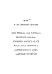
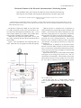
Figure 1 shows the HMS unit cell comprising these elements. Monitored crates and signals are listed in the appendix.
CDRs and ACSCs are configured with a combination of
National Instruments’ (NI) hot plug and play Field Point (FP)
modules: network (FP-1600), discrete input (DI-330), relay
(RLY-420), analog input (AI-110), and resistance temperature
detector (RTD-122); details are provided in the appendix.
Modules are mounted on terminal bases that attach to the
power-bus and to the communications-bus. The terminal
bases have screw-terminals for hook-up to other components
and connectors. All modules are housed in a 34”-deep-rackmountable box.
Communications are handled by the FP-1600s and the
Ethernet card in the HMS computer located in the counting
house. The FP-1600s, downloaded with monitoring software3
written in NI’s developer suite, LabVIEW, are connected with
CAT 5 cables to the network.
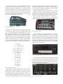
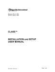
Figure 2 shows the top view of the CDR. The FP modules
in the upper level are arranged in up to three rows. Each row
can hold up to five FP modules. These modules connect to the
barrier blocks in the lower level by 24AWG wires, from where
the wires hook to connectors on the front and rear panels.
FIG. 2. CDR top view.
On the front panel, Fig. 3, circular plastic connectors
(CPCs) provide outputs for other control systems, such as
EPICS.
FIG. 1. HMS unit cell.
FIG. 3. CDR front panel.
1
upon which analysis generates temperature signals that are
transmitted via RS232 to the computer. Status signals are
converted to Boolean signals and displayed as either red (fail)
or green (pass) lights on the front panel.
Monitoring cards for different types of crates have different features. CAMAC crate monitoring cards (CCMCs)5 do
not have an AC voltage input; hence CCMCs do not have
the AC/DC conversion block. The data path, Fig. 5, of the
CCMCs is similar to that of, not identical to, the NCMCs.
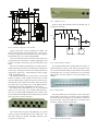
The ACSC, Fig. 6 shows the top view, is built like the
CDR. ACSCs are configured with RLY-420s and FP-1600s.
On the rear panel, Fig. 4, CPCs accept data from the different crates that are monitored. Network connectors – one for
each FP-1600, enable communication. A switch and BNC
connector facilitate local and remote reset respectively. The
bottom row of BNC connectors are for data inputs from the
CAEN2 power supplies. The power block located at the bottom center connects to the Acopian 24 VDC 30 A power supply (APS). An LED indicates reset status.
FIG. 4. CDR rear panel.
CDRs receive CPS from the built-in status connectors of
the CAEN power supplies and from the ADB, VME and VXI
crates. Since NIM, CAMAC and FASTBUS crates do not
have built-in status connectors, monitoring cards with ADCs
and I/O controls – handled by PICs, were designed and fabricated to read CPS values from the back plane of the crates, to
transmit these values to the HMS computer and to determine
whether the acquired values are within operational limits,
based upon which determination signals are generated to issue a red alert and to display crate status on the front panel.
FIG. 6. ACSC top view.
Figure 7 shows the front panel of the ACSC. Each monitored crate is assigned two white RTD connectors. CPC connectors that send data to other control systems are located in
the four quadrants. Two red LEDs that indicate 24 VDC input
and 12 VDC output are on the top left and right corners. Green
LEDs along the top indicate reset occurrence. Fuses for BRM
outputs, ACSC power, output of the internal 12 VDC supply,
and FP-1600s are in the center.
FIG. 7. ACSC front panel.
A switch and a BNC connector, at the top right-hand corner
of the rear panel, Fig. 8, enable manual or remote reset of the
FP-1600. The row of BNC connectors at the bottom are for
resetting different crates. The power block located at the bottom center is connected to the PRM.
FIG. 5. Data path of signals.
The NIM crate monitoring card (NCMC) uses a full-wave
voltage rectifier to convert 120 VAC to 120 VDC. Negative
DC voltages are inverted and back plane voltages (BPVs) are
reduced4 with the aid of operational amplifiers. The PIC converts the BPVs into digital signals. NCMC has a temperature
sensor, whose voltage output the PIC reads, analyzes, based
FIG. 8. ACSC rear panel.
2
FIG. 11. PRM rear panel.
Figure 12 shows the schematic of the reset module, Fig. 13
its physical realization.
1
2
3
20
4
5 VDC
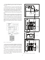
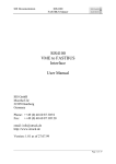
FIG. 9. Schematic of the power router module.
Figure 9 shows one of the six channels of a PRM. The
power section consists of two dual pin CPCs - top CPC provides power input from the APS, bottom one power output to
an individual ACSC or to a daisy chained PRM.
The relay is normally closed. The open contact of the relay
is connected to the “Reset Active” LED Energizing the relay
switches it from the closed to the open state and turns on the
LED.
The tease-less double pole double throw switch in the normal position powers the ACSC and maintains constant power
to the relays. Setting the switch to the manual position deenergizes the output CPC. LEDs indicate presence of input,
output, and manual power.
The channel section has two nine-pin CPCs, one for input
and one for output. ACSC signals are sent to pin six of the
input, providing control voltage for the power section’s relay.
The normally closed contacts of the relay connect the APS to
the output’s pin six providing power to the BRM contactor,
thus holding the normally open BRM contactor closed.
The front panel of the PRM, Fig. 10, a rack-mountable
chassis, has six red LEDs, one per channel that indicate reset active, an orange LED that indicates power status, a red/
green combination LED that indicates manual (red) or normal
(green) operation, and I/O connectors.
CPC 23
CPC 23
Output CPC
FIG. 12. Reset module’s schematic.
The module installed in the counting house has twenty external momentary switches, each with its own LED to indicate a reset and with the ability to control in the relay module
an individual relay. The relay controls power to a particular
HMS chassis’ FP-1600, which is reset by activating a reset
channel.
FIG. 13. Reset module.
The relay module, Fig. 14, located on level one of the space
frame, houses twenty relays. Each relay can be controlled by
the switches on the front panel or by momentary switches on
the reset module. Each relay channel uses a normally closed
contact to sustain voltage to an FP-1600.
FIG. 10. PRM front panel.
The switch on the rear panel of the PRM, Fig. 11, (top left
corner), permits de-energizing the power output CPC. The
other CPC connects to an APS. The BNC connector on the
rear panel is for future use.
FIG. 14. Relay module front panel.
3
The relay module has a CPC input for the cables from the
reset module and BNC outputs for cables to the CDRs and
the ACSCs.
The relay module uses a 57-pin CPC for the multi-conductor cable that is routed to distribution modules installed in the
forward carriage and in the pie tower. The multiconductor
cable is unbundled in the distribution modules and BNC outputs are provided for cables to the CDRs and the ACSCs.
During beam, power cycling to reset crates or to re-establish network connections is done from the counting house by
RRS.
RRS for crate reset is initiated via the LabVIEW GUI6.
Figure 15 shows the schematic of the crate reset system. Once
a crate is selected, reset-data is sent over the network via the
FP-1600 to the appropriate ACSC’s RLY-420, which sends a
24 VDC level to a relay (normally closed) in the PRM, opening the relay briefly (~ ms) to interrupt power to the coil of the
BRM’s contactor, which connects the crate to its AC power.
The power interruption opens this contactor, rebooting the
crate.
1
2
3
4
20
5 VDC
CPC 23
CPC 23
Output CPC
Reset Module
Multi conductor
Bundle
CPC 23
1
2
3
4
Input CPC
20
5 VDC
Relay Module
CPC 23
Output BNC
Forward Carriage Output CPC
RG-58
20
V+ input on
FP1600
24 VDC
Multi conductor Bundle
HMS Chassis
CPC 23
Input CPC
FIG. 15. Crate reset system.
1
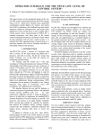
Figure 16 shows the schematic of RRS for communication
outage. RRS is activated for the appropriate unit by selecting
a momentary switch on the reset module. This action sends
a 5 VDC level to the relay module in which the selected relay momentarily (~ ms) interrupts power to the intended FP1600.
To conclude, these HMS hardware components designed,
fabricated, tested and installed in the end station, in phases
since 2001, by the Hall B Instrumentation group are functioning as anticipated. HMS is contributing towards safer and
smoother CLAS operations.
2
3
4
10
5 VDC
Forward
Carriage
Distribution
Module
Output BNC
FIG. 16. Schematic of network reset system.
4
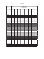
APPENDIX
Monitored
Signals
and Controls
+5 (I)
-5.2 (I)
-2 (I)
+15 (I)
-15 (I)
AC OK
AC Reset
CH Status
Check Passed
Crate Temp 1
Crate Temp 2
DC OK
DC OK +5
DC OK –5.2
DC OK -2
DC OK +15
DC OK -15
Fan Status
HV Error
Interlock
(I) Trip +5
(I) Trip –5.2
(I) Trip -2
(I) Trip +15
(I) Trip -15
Module Reset
Over Temp
Power Fail
Reset 1
Smoke Alarm
System Reset
TCI Reset
Crate Types
(Number of Crates)
ADB
(31)
CAEN
(7)
CAMAC
(20)
√
√
√
√
√
√
√
√
√
√
√
√
√
FASTBUS
(18)
√
√
√
√
√
√
√
LeCroy
(15)
NIM
(37)
VME
(12)
VXI
(3)
√
√
√
√
√
√
√
√
√
√
√
√
√
√
√
√
√
√
√
√
√
√
√
√
√
√
√
√
√
√
√
√
√
√
√
√
√
√
√
√
√
√
√
√
√
√
√
√
√
√
√
√
√
√
5
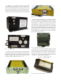
The BRM’s, Fig. 1, normally-open-208 VAC-three-phase
AC-contactor or normally-open-120 VAC- relay that is capable of switching high currents, connects a single crate to its
AC source as well as to an AC circuit, which detects AC power status and transmits that data to the ACSC, which after processing the data relays the information to the main computer.
FIG. 2. Acopian power supply.
The FP-1600 network module, Fig. 3, provides an interface
between the TCP/IP network and the FP data bus, which can
have up to ten FP modules (including the FP-1600s). Housed
in the module is a watchdog timer, which monitors network
communications. If there is no communication with the network beyond the programmed time interval, the watchdog
timer returns all connected modules to their default state. Another feature of the FP-1600 is its ability to store a snapshot of
the programmable power-up state in its memory. This feature
sets the module in a predictable state in case of a power failure and faciliates easy power-up.
FIG. 3. FP1600 network module.
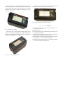
The DI-330, Fig. 4, that reads status signals, has eight
universal discrete, optically isolated input channels that accept TTL, CMOS, DC, and AC signals. These channels can
be used to sink, source or sense power. Input voltage may
range from 5 — 250 VDC/VAC with maximum input current
< 1.5 mA. The module fucntions as follows:
ON ; VDC >2.5
DI_register =
OFF ; VDC <1
FIG. 1. BiRa reset module.
The APS, Fig. 2, provides the 24 VDC needed to close both
the contactor and the relay of the BRM. The APS has floating outputs, built-in short circuit protection and has remote
sensing of output voltage at the load. The APS is rated for
operation at ambient temperatures up to +71°C.
{
FIG. 4. DI-330 discrete input module
6
The RTD-122, Fig. 7, used to measure any resistive sensors up to 4 kΩ, is an eight-channel input module.
The RLY-420, Fig. 5, that enables remote reset of backplane or of AC power to crates and other instruments, houses
eight normally open single pole single throw relay output
channels, each of which is capable of switching 3 A, up to
35 VDC or 250 VAC.
FIG. 7. RTD-122 resistance temperature detector.
[1] For an overview of the system, see M.A. Antonioli, et.al.
CLASNOTE 2003-18.
[2] Company name
[3] For an overview of the software design, see B. Eng et.al.
CLAS-NOTE 2004-001.
[4] All BPVs are reduced by a factor of six, except for the 120
VDC, which is reduced by a factor of 100.
[5] Details of the CAMAC crate monitoring card are given by
M. Ferguson et. al. in CLAS-Note 2004-007.
[6] Details on operating the GUI are given in the user manual
located in the Hall B counting house.
FIG. 5. RLY-420 relay module
The AI-110, Fig. 6, that monitors analog signals from a
variety of sensors and transmitters has eight analog input
channels; each channel has 16 bits and can be configured via
software for voltage or current inputs.
FIG. 6. AI-110 analog input module.
7