1
GE Consumer & Industrial
Electrical Distribution
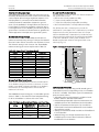
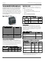
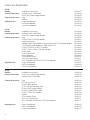
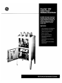
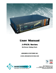
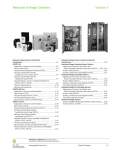
E2000 Miniature
Circuit Breakers
Application Flexibility
• Dual AC & DC Ratings
• 6 kAIC & 10 kAIC Interruption Ratings
@ 480Y/277 Vac
• C & D Trip Characteristics from 0.5 to 63 A
• B Trip Characteristics from 5 to 63 A
• Standard North American 5, 15, 30 & 60 A Ratings
• Left & Right Side Accessory Mounting –
Up to 4 per Side
• 35mm DIN-rail Mounting
• UL Recognized & CSA Approved
imagination at work
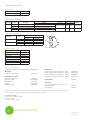
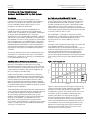
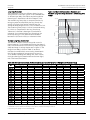
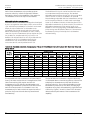
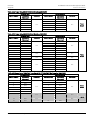
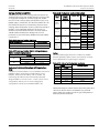
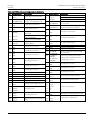
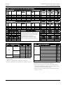
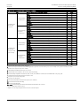
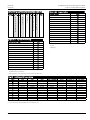
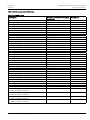
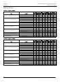
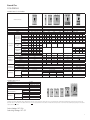
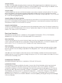
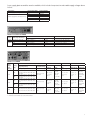
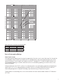
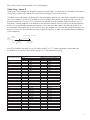
E2000 Miniature Circuit Breakers
Short Circuit Capacity
Per UL 1077 (File E151139) & CSA 22.2 (No. 235-1989)
EP60
Poles
1
2
3, 4
Max. Voltage Rating
AC
DC
277
50
480Y/277
110
480Y/277
110
Short Circuit Rating kAIC RMS Symmetrical
120
120/ 240
277
480Y/ 277
10
–
6
–
10
10
6
–
10
10
6
10
50
10
–
–
kAIC DC
Max. Voltage Rating
AC
DC
277
50
480Y/277
110
480Y/277
110
Short Circuit Rating kAIC RMS Symmetrical
120
120/ 240
277
480Y/ 277
10
–
10
–
10
10
10
–
10
10
10
10
50
10
–
–
110
–
10
–
EP100
Poles
1
2
3, 4
EP100UC (not UL or CSA approved)
AC acc. to IEC 60898-2
Poles
2
110
–
10
–
EP100ULH
AC acc. to UL 489
V
125 DC
220 DC
230/400 AC
250 DC
440 DC
400 AC
1
kAIC DC
Icn/Ics (kA)
10
6
6
10
6
6
Poles
1
2
Poles
1
V
240 AC
Icn/Ics (kA)
10
Icu (kA)*
30
15
4
40
30
2
2, 3
For use in interpreting catalog numbers only.
Do not use to construct catalog numbers.
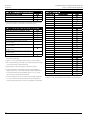
EP60, EP100, EP100UC
36
V
127
240
415
127
240
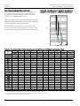
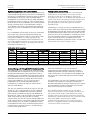
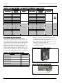
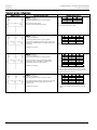
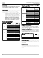
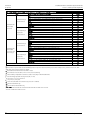
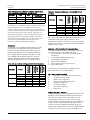
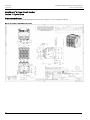
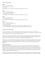
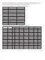
Catalog Number Structure
Dimensions
18
Icc (kA)
10
10
AC acc. to IEC 60947-2
AC acc. to IEC 60947-2
Poles
1, 2
V
120
240
54
72
70
44
6
EP
45
86
6
3
UL
C
0.5
GE Product Series
Ampere Rating
0.5–63 Amperes
Interruption Rating
EP100ULH
6
10
6 kAIC, 480Y/277
10 kAIC, 480Y/277
or 10 kAIC, 125Vdc
Agency/Standard Approval
# of Poles
1
2
3
4
Instantaneous 3–5 X
Instantaneous 5–10 X
Instantaneous 10–20 X
B
C
D
1 Pole
2 Pole
3 Pole
4 Pole
UL
UC
ULH
UL 1077 & CSA 22.2
EN 60898-2
UL 489
GE Consumer & Industrial
41 Woodford Avenue, Plainville, CT 06062
www.geelectrical.com
© 2007 General Electric Company
imagination at work
DET-430A (07/07)
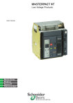
GE Consumer & Industrial
Electrical Distribution
™
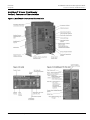
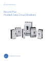
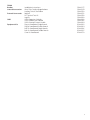
Record Plus FG 600
Current Limiting Molded Case Circuit Breakers
Catalog/Selection Guide
imagination at work
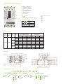
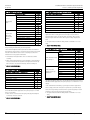
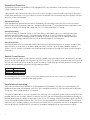
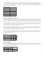
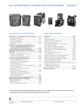
FG 600 Amp Frame Overview
u
u Breaker Frame Rating
v Product Description
w Standards & Markings
x Interrupting Ratings
y Lug Data & Torque Info
z Catalog Number
{ Push to Trip
v
w
x
y
z
Main Standards
• UL 489
• IEC 947 and associated EN Sections
{
FG Breaker Markings
UL file E-11592
HACR
Cu/Al 60/75°C
Current Limiting
Other Global Standards
• BS
• CE
• CEI
• JIS
• UNE
• VDE
250 to 600A
250 to 600A
250 to 600A
Not suitable for reverse feed.
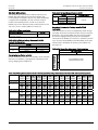
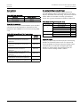
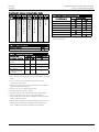
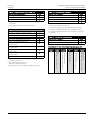
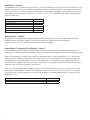
Interrupting Ratings
Ampere Maximum
Rating
Voltage
Type
UL Listed Interrupting Rating
rms Symmetrical Amperes
(Thousands) AC Voltage
240
480
600
Poles
FGN
FGH
250-600A 600 Vac
FGL
FGP
2
150
3
2
EN 60947-2 Interrupting Rating
rms Symmetrical Amperes
(Thousands)
240
400-415
690
65
25
N/A
N/A
N/A
150
65
25
85
50
10
200
100
35
N/A
N/A
N/A
3
200
100
35
100
80
22
2
200
150
42
N/A
N/A
N/A
3
200
150
42
200
150
40
2
200
200
65
N/A
N/A
N/A
3
200
200
65
N/A
N/A
N/A
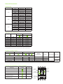
Dimensions
Catalog Number Structure
F
Family
F = Record
Plus
Frame Rating Interruption
(Amperes) Capacity (kA
@ 480VAC)
G =600
N = 65kA
H = 100kA
L = 150kA
P = 200kA
G
N
3
6
AA
250
Voltage
Poles
Rating (Max)
Trip Type
3 =3 Pole
6 = 600VAC AA = SMR1
(No Rating
2 =2 Pole
(in 3 Pole
Plug)
Frame)
R0
Rated
Current (A)
Connection
Option
250 = 250 R0 = Standard, No Lugs
400 = 400 R1 = Line and Load Lugs
600 = 600 R2 = Load Lugs
R3 = Line Lugs
Internal Accessories
FG Rating Plugs
CT Rating
Rated Current
125A
150A
175A
200A
225A
250A
175A
200A
225A
250A
300A
350A
400A
300A
350A
400A
450A
500A
600A
250A
400A
600A
Catalog Number
FGRP3K0125
FGRP3K0150
FGRP3K0175
FGRP3K0200
FGRP3K0225
FGRP3K0250
FGRP3L0175
FGRP3L0200
FGRP3L0225
FGRP3L0250
FGRP3L0300
FGRP3L0350
FGRP3L0400
FGRP3M0300
FGRP3M0350
FGRP3M0400
FGRP3M0450
FGRP3M0500
FGRP3M0600
Trip Curve
DES-042
DES-043
DES-044
DES-045
DES-046
DES-047
DES-048
DES-049
DES-050
DES-051
DES-052
DES-053
DES-054
DES-055
DES-056
DES-057
DES-058
DES-059
DES-060
Shunt Trip & Undervoltage Release
Shunt Trip
Vac
24
48
110 - 130
120
220 - 240
277
400 - 480
Vdc
12
24
48
110 - 125
250
-
Undervoltage Release
Catalog Numbers
FASHTBW
n/a
FASHTDW
FAUVRDW
FASHTFW
FAUVRFW
FASHTJW
FAUVRJW
FASHTKW
FAUVRKW
FASHTNW
FAUVRNW
FASHT7W
FAUVR7W
FASHTUW
FAUVRUW
UL Listed for field installation. Accessories are prewired from the factory with 36 inch
long leads (#18 AWG). Shunt trip wire leads are black and UVR wire leads are blue.
Bell Alarm & Auxiliary Switches
Bell Alarm Mechanisms Bell Alarm Trip Units
Auxiliary Switches
Contact
Configuration
Contacts
1 NO (Form A)
1 NC (Form B)
1 NO/NC (Form C)
1 NO/NC (Form C)
Standard
Standard
Standard
Gold plated
Contact Rating
Wire Leads
5A @ 277Vac
0.3A @ 125Vdc
#16 AWG
Catalog Numbers
FABAM10W
FABAM01W
FABAM11W
FABAM11GW
FABAT10W
FABAT01W
—
—
FAS10LW
FAS01LW
FAS11LW
FAS11LGW
FAS10RW
FAS01RW
FAS11RW
FAS11RGW
1A @ 30Vac/dc
UL Listed for field installation. Accessories are prewired from the factory with 36 inch long leads. Reference instruction sheet DEH-40324 for wire lead colors.
Internal Accessory Mounting Locations & Limitations
Accessory
Mounting Pocket
Location
Maximum
Quantity
Shunt Trip or Under Voltage Release
1
Aux. Switch - Left Mount
3
Aux. Switch - Right Mount
2
Bell Alarm Mechanism
1
Bell Alarm Trip Unit
1
Auxiliary
Switch
Bell Alarm
Mechanism
Shunt Trip or
Undervoltage
Release
Auxiliary
Switch
Bell Alarm
Trip Unit
#18 AWG
External Accessories
Padlock Device
Description
Catalog Number
Padlock, EUSERC Toggle
FG1PE
Lug Kits
Lugs are tin-plated aluminum
Poles/Lugs
2
3
Location
Top
Bottom
Top
Bottom
Torque
Wire-Lug
Lug-Strap
#8-400kcmil Cu, #6-500kcmil Al #8-#4 AWG Cu/Al 275 lb-in (31 N-m)
200 lb-in (23 N-m)
#2/0-600kcmil Cu/Al
#3 AWG-600kcmil Cu/Al 375 lb-in (42 N-m)
#8-400kcmil Cu, #6-500kcmil Al #8-#4 AWG Cu/Al 275 lb-in (31 N-m)
200 lb-in (23 N-m)
#2/0-600kcmil Cu/Al
#3 AWG-600kcmil Cu/Al 375 lb-in (42 N-m)
Wire Type
Strip Length
Top
Bottom
Catalog
Number
7/8”
1 5/8”
FCALK218H
7/8”
1 5/8”
FCALK318H
Panelboard Mounting Kits
Panelboard
Poles
Spectra Series Plug-in
Spectra Series Bolt-on
2
3
2
3
Catalog Number
Double Branch
Single Branch
AMC4FGB
AMC2FGM
AMC6FGB
AMC3FGM
AMCB4FGB
AMCB2FGM
AMCB6FGB
AMCB3FGM
Top
Bottom
FCALK218H/FCALK318H
Other Accessories
Accessory
Catalog Number
Rating Plug Removal Tool
FAR
Breaker External Test Kit
FAT
Lug Cover Kit
FG1BCK
Replacement Trip Unit Shield
FG1TUSHLD
Replacement Handle Extension FGHDLEXT
Hardware Kit (Tapped Holes)
FGMSK1
Hardware Kit (Through Holes)
FGMSK2
Publications & References
Available for download from www.geelectrical.com/publibrary
FG Breaker
Installation Instructions
DEH-41177
FG Breaker Accessories
Bell Alarm & Aux. Switch
Shunt Trip & UVR
Padlock Device
Lug Kits
Auxiliary Contacts
DEH-40324
DEH-40259
DEH-41031
DEH-40404
DEH-40261
Panelboards
Spectra Power Panel - Plug-in Kits - Single
Spectra Power Panel - Plug-in Kits - Double
Spectra Power Panel - Bolt-on Kits - Single
Spectra Power Panel - Bolt-on Kits - Double
DEH-40420
DEH-40419
DEH-40426
DEH-41047
Series Ratings
DET-008
Trip Curves
(See FG Rating Plugs Table for Rating Plug Trip Curves)
Peak Current Curve
Peak I2t Curve
DES-040
DES-041
Data are subject to change without notice. Should further information be desired, or should particular problems arise that are not sufficiently covered
here for the purchaser’s purposes, the matter should be referred to the General Electric Company.
GE Consumer & Industrial
41 Woodford Avenue, Plainville, CT 06062
www.geelectrical.com
© 2007 General Electric Company
imagination at work
DEA-382A (04/07)
Printed in U.S.A.
GE
Electrical Distribution
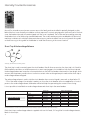
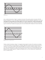
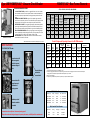
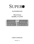
Gerapid High Speed DC Circuit Breakers
On the move
imagination at work
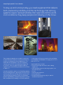
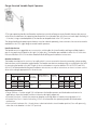
Gerapid High Speed DC Circuit Breakers
To stay up and running today, you need equipment that delivers
both unwavering reliability and the technology 21st century
systems require. Gerapid satisfies that need. Around the world,
in all conditions, they keep people and industry on the move.
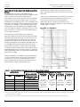
These single-pole breakers are suitable for protection
of mains and semiconductors (converters/rectifiers) in
a variety of railway and industrial applications. The
feeder and rectifier breakers come with operating
currents up to 8,000ADC and operating voltages up
to 3,600VDC. Their very high interruption capacity
combines with current limiting characteristic as shown
in Tables 1-3.
Innovative materials, superior circuit breaking capacity
and outstanding dielectric performance ensure service
continuity and protection during adverse system events.
The technology and quality of these circuit breakers
produce high reliability, extended maintenance intervals
and uncomplicated serviceability for all fixed installations.
A wide range of fully accessorized rectifier and feeder
circuit breakers are available. All comply with IEC 947-2
and ANSI C37.14.
Typical applications include:
• traction power (light rail transit, tram, subway,
maglev, etc.)
• industrial plant protection (electrolysis plants, iron
and steel mills, etc.)
• mining
• chemical, petrochemical
• power generation
• research/experimental (e.g., physics, particle
accelerator protection)
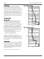
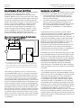
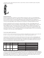
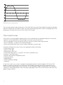
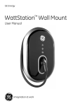
Typical Traction Electric Power System
Rectifier CBs
protect converters
AC bus duct
Electric utility
Primary switchgear, 5kV-38kV
Transformer
Heavy duty traction rectifier
Feeder CBs distribute
DC to the track
DC bus duct
DC switchgear
Third rail
or overhead
contact system
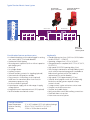
Circuit Breaker Features and Accessories
• Insulated side plates with insulated toggle for setting
over current trip (OCT) for feeder breakers
• Mechanical forced tripping
• Electrodynamic trip device (with or without capacitor
and charging unit)
• Shunt trip
• No-voltage release
• Auxiliary contacts
• Different auxiliary contacts for signaling (optional)
• Main terminal configurations variable
• Plug connectors for auxiliary circuits (optional)
• Hand lever for manual actuation from front (for
maintenance purposes only)
• Position indication (optional)
• Internal power supply with a wide range of supply
voltage options
• Integrated current measurement unit (SEL) (optional)
• Rectifier breaker mechanical counter
General Information
Rated Temperature
Relative Humidity
Altitude
Key Benefits
• Standard dimensions from 2,600A to 6,000A (feeder
models GER2607 – GER8007)
• Operating voltages from 1,000 to 3,600VDC
• Mining and traction compliant (ANSI C37.14, IEC 947-2,
EN 50123-2)
• High speed OPEN/TRIP (opening delay <3ms)
• Direct acting instantaneous and adjustable trip unit
works without imported energy and is available as
bidirectional symmetrical (for line feeder) or
undirectional (for rectifier breaker)
• High speed CLOSE (approximately 150 ms)
• Solenoid drive (integral control unit, mechanically
latched, no auxiliary power required to keep
contacts closed)
• 2-stage contact system minimizes contact wear
• Compact, enclosed construction
• Modular, serviceable design
• Easily accessible control and auxiliary connections
• Fixed and draw-out versions
• Extensive accessories/options
-5° to 40°C ambient (55°C with reduced ratings)
90% @ T<20°C; RH=130-2*T @ T>20 °C
-120m to 2000m above sea level
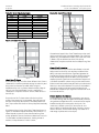
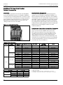
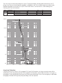
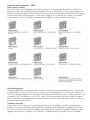
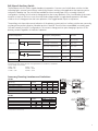
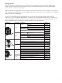
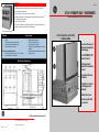
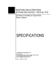
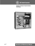
Gerapid Breaker Modules
Power and Control Connections
Control circuits –
screw terminals and
plug-in connectors
Arc chute
(1x2 shown, 1,000VDC)
Arc chute adapter
Insulated side plates
(optional)
Instantaneous trip –
mechanically operated
(adjustable, optional)
Electronic control unit
Basic breaker with drive
mechanism and
contact system
Solenoid drive
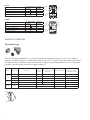
Type SEL Current Measurement
System (optional on 2607 and 4207)
• Current measurement at the breaker
• Factory-equipped or field-installable
• No additional space required or
breaker modifications
• Ranges 6kA and 12kA
• To 4,000VDC
• Signal output via 3 interfaces
• 4...20mA
• +/- 20mA
• +/- 10V
• Watchdog function standard
Main terminals, horizontal
and vertical, top and bottom
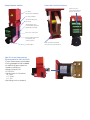
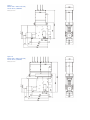
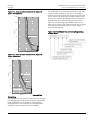
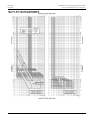
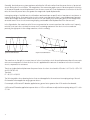
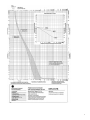
Figure 1.
Models 2607 - 6007 Feeder CBs,
1X4 Arc Chute, 2,000VDC
Dimensions in mm
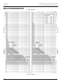
Figure 1A.
Models 2607 - 6007 Feeder CBs,
2X4 Arc Chute, 3,600VDC
Dimensions in mm
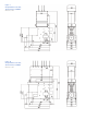
Figure 2.
Gerapid 8007 Feeder CBs,
1X4 Arc Chute, 2,000VDC
Dimensions in mm
Figure 2A.
Gerapid 8007 Feeder CBs,
2X4 Arc Chute, 3,600VDC
Dimensions in mm
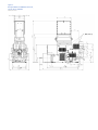
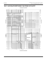
Figure 3.
Gerapid 8007R and 10007R Rectifier CB,
1X2 Arc Chute, 800VDC
Dimensions in mm
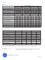
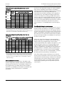
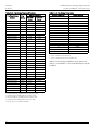
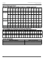
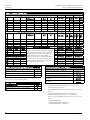
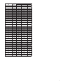
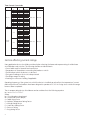
Technical Data
Table 1.
Gerapid FCB
Gerapid Breaker Type
2607
4607
Arc chute type
1X2 1X4 2X2 2X3 2X4 1X2 1X4 2X2 2X3 2X4 1X2
Conventional thermal current Ith [A] (IEC/EN)
2600
4200
Rated current [A] (ANSI/IEEE C37.14)
2600
4150
Rated voltage UNe [V]
1000 2000 2000 3000 3600 1000 2000 2000 3000 3600 1000
Rated voltage [V] (ANSI/IEEE C37.14)
800
800
1600
Rated insulation voltage Ui [V]
2000 2000 2000 3000 4000 2000 2000 2000 3000 4000 1000
Short time current 120 min [A]
3150
5000
Short time current 2 min [A]
5200
8500
Short time current 20 sec [A]
7800
12600
Impulse withstand voltage 1,2/50 μs Ui [kV]
18 18 18 30 30 18 18 18 30 30 12
according to EN 50124-1:1997
Power frequency withstand voltage 50 Hz
10 10 10 15 15 10 10 10 15 15 7
Ua [kVeff] according to EN 50124-1:1997
Rated short circuit making capacity INss [kA] 70 50 100 50 42 70 50 100 50 42 70
Rated short circuit breaking capacity INss
50 30 71 35 30 50 30 71 35 30 50
[kA] according to EN 50123-2
Rated service short circuit breaking current
60 40 50 40 40 60 40 50 40 40 60
Ics [kA] according to IEC 60947-2
Short circuit current [kA] at Une = 800 VDC 200
200
Short circuit current [kA] at Une = 1600 VDC
*
100
Maximum short circuit current test [kA]
244 120 100
52 244 120 100
52 200
Maximum arc voltage Uarc [kV]
2
4
4
5.6 7
2
4
4
5.6 7
2
Weight ca. [kg]
120 120 160 160 160 120 120 160 160 160 150
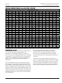
Specification
6007
8007
1X4 2X2 2X3 2X4 1X2 2X2
6000
8000
*
6000
2000 2000 3000 3600 1000 2000
800
2000 2000 3000 4000 1000 2000
7200
9600
12000
16000
18000
24000
18
18
30
*
12
18
10
10
15
*
7
10
50
80
50
*
70
*
35
56
35
*
50
50
40
50
40
*
60
*
200 *
*
240
4
4
5.6 7
2
4
150 165 165 165 190 210
*
*Characteristic tests at customer request.
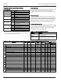
Table 2.
Gerapid 8007R & 10007R
Parameter
Arc chute type
Rated continuous current [A]
2 hours current [A]
2 minutes current [A]
20 seconds current [A]
Rated short-time current (250ms) [kA]
Rated maximum voltage [V]
Rated insulation voltage - UNm [V]
Rated impulse voltage - UNi [kV]
Power frequency voltage - Ua [kV]
Mechanical endurance [cycles] 1
Rated short circuit peak / sustained [kA / kA] 2, 3
Short-circuit characteristic
Maximum arc voltage [V]
Mass ca.
Reference
N/A
ANSI C37.14 p.5.3
N/A
N/A
N/A
ANSI C37.14 p.5.5
ANSI C37.14 p.5.2
EN 50124-1 p.1.3.2.4
EN 50124-1 p.1.3.2.7
EN 50124-1 a.B2.2
N/A
ANSI C37.14 p.5.4
Tests a,b,c,d acc.
ANSI C37.14 annex A
N/A
N/A
Gerapid 8007R
1x2
1x3
6000
6000
7200
7200
12000
12000
18000
18000
90 (149 peak)
60 (100 peak)
800
1200
2000
2000
18 [1,2/50μs]
18 [1,2/50μs]
10 [1min. 50Hz] 10 [1min. 50Hz]
10000
10000
200 / 120
132 / 80
Gerapid 10007R
1x2
1x3
8000
8000
9600
9600
16000
16000
24000
24000
90 (149 peak)
60 (100 peak)
800
1200
2000
2000
18 [1,2/50μs]
18 [1,2/50μs]
10 [1min. 50Hz] 10 [1min. 50Hz]
10000
10000
200 / 120
132 / 80
High-speed
High-speed
High-speed
High-speed
2500
220 kG
2500
220 kG
2500
220 kG
2500
220 kG
1 10.000 cycles without parts replacement. Inspection after 5.000 cycles. Max. 5.000 cycles by means of ED impulse coil or POCT release.
2 Tested for high and low frequency impedance bonds.
3 Trip by means of POCT (direct-acting, instantaneous, electromechanical and polarized OC release) or by means of ED impulse coil with no intentional delay.
GE
41 Woodford Avenue, Plainville, CT 06062
www.geelectrical.com
© 2010 General Electric Company
Information provided is subject to change without notice. Please verify all details with GE. All values are design or
typical values when measured under laboratory conditions, and GE makes no warranty or guarantee, express or
implied, that such performance will be obtained under end-use conditions.
imagination at work
DEA-379A (02/10)
Printed in U.S.A.
GE
Electrical Distribution
EntelliGuard G
®
Circuit Breaker
Application Guide
imagination at work
DET-653A
02 Apr 09
EntelliGuard® G Circuit Breaker Application Guide
Table of Contents
SECTION 1 – GENERAL INFORMATION
Introduction ....................................................................................................................................................................................................... 1
Table 1.1. Device Standards and References ........................................................................................................................... 1
Table 1.2. Device Ratings ................................................................................................................................................................... 1
Table 1.3. ANSI/UL1066 Ratings ..................................................................................................................................................... 2
Table 1.4. UL489 Ratings.................................................................................................................................................................... 2
Table 1.5. Non-Automatic Circuit Breaker – ANSI Version Ratings................................................................................. 2
Table 1.6. Non-Automatic Circuit Breaker/Molded Case Switch – UL Version Ratings......................................... 2
SECTION 2 – FEATURES AND CHARACTERISTICS
Figure 2.1. EntelliGuard G Features and Characteristics.............................................................................................................. 3
STANDARD AND OPTIONAL FEATURES .................................................................................................................................................. 4
Short Time Rating................................................................................................................................................................................... 4
Short Circuit/High Interruption Rating ......................................................................................................................................... 4
Thermal Performance .......................................................................................................................................................................... 4
Table 2.1. Sensors Available..................................................................................................................................................... 4
Reverse Feed............................................................................................................................................................................................ 4
Two-Step Stored Energy Mechanism............................................................................................................................................ 4
Field Installable Trip Units and Accessories............................................................................................................................... 4
Coils
...................................................................................................................................................................................................... 4
Breaker/Main Contact Status ........................................................................................................................................................... 4
Motor Operator ....................................................................................................................................................................................... 4
Electrical Closing Button ..................................................................................................................................................................... 4
Ready to Close Indicator..................................................................................................................................................................... 4
Mounting Straps/Accessories........................................................................................................................................................... 5
Auxiliary Switches (Optional)............................................................................................................................................................. 5
Interlocks.................................................................................................................................................................................................... 5
Breaker Status Indicators................................................................................................................................................................... 5
Rejection Feature ................................................................................................................................................................................... 5
Through-Door Racking ........................................................................................................................................................................ 6
Padlocking Devices................................................................................................................................................................................ 6
Key Interlock............................................................................................................................................................................................. 6
Shutters ...................................................................................................................................................................................................... 6
Carriage Position Switch..................................................................................................................................................................... 6
Lifting Truck............................................................................................................................................................................................... 6
IP Covers..................................................................................................................................................................................................... 6
Mechanical Counter.............................................................................................................................................................................. 6
Cable Interlocks (OEM Applications Only).................................................................................................................................... 6
Bell Alarm Contact ................................................................................................................................................................................. 6
SECTION 3 – ENTELLIGUARD TU TRIP UNIT SYSTEM
Introduction ...................................................................................................................................................................................................... 7
Reliability without Compromising Protection..................................................................................................................................... 7
Arc Flash and the EntelliGuard TU Trip Unit........................................................................................................................................ 7
Figure 3.1. Arcing Current................................................................................................................................................................... 7
Selectivity with Molded case Circuit Breakers and Other Devices ........................................................................................... 8
Table 3.1. EntelliGuard Selectivity above GE Current Limiting Circuit Breakers........................................................ 8
Figure 3.2. Selectivity Curve............................................................................................................................................................... 8
Table 3.2. Maximum Selectivity Above Non Current Limiting CB (UL 489)................................................................... 9
Table 3.3. Maximum Selectivity Above Non Current Limiting CB (UL 1066)................................................................ 9
Above Downstream Feeders...................................................................................................................................................................... 9
The Adjustable Selective Instantaneous .............................................................................................................................................. 9
Table 3.4. Minimum Selective Clearing Times for an EntelliGuard G Circuit Breaker ...........................................10
® 2009 General Electric All Rights Reserved
EntelliGuard® G Circuit Breaker Application Guide
Table of Contents
DET-653A
02 Apr 09
Above Other Power Circuit Breakers....................................................................................................................................................10
Terminology .....................................................................................................................................................................................................10
Long Time Protection ............................................................................................................................................................................11
Thermal Long Time Overcurrent............................................................................................................................................................11
Figure 3.3. Thermal Characteristic: Max. and Min. Long Time Delay Bands for a 1000A Long Time Pickup....... 11
Table. 3.5. Thermal Characteristic: Nominal Clearing and Commit Times for X Multipliers of Nominal Pickup 11
Fuse-Shaped Steep Long Time Overcurrent ....................................................................................................................................12
Figure 3.4. Fuse Characteristic: Max. and Min. Long Time Delay Bands for a 1000A Long Time Pickup .............12
Table 3.6. Fuse Characteristic: Nominal Clearing and Commit Times for X Multipliers of Nominal Pickup ........12
Thermal Memory ...........................................................................................................................................................................................13
Short Time Protection..................................................................................................................................................................................13
Short Time Pickup ................................................................................................................................................................................13
Figure 3.5. Short Time Pickup ................................................................................................................................................13
Figure 3.6. Short Time Transition .........................................................................................................................................13
Short Time Bands .................................................................................................................................................................................13
Table 3.7. Short Time Delay Bands......................................................................................................................................14
Figure 3.7 Short Time Delay ...................................................................................................................................................14
2
Short Time I t Slopes ...........................................................................................................................................................................14
Figure 3.8. Short I2t (In or Out)................................................................................................................................................14
Ground Fault Protection.............................................................................................................................................................................14
Internal Residual Summation ..................................................................................................................................................................14
External Zero Sequence Input.................................................................................................................................................................15
Ground Fault Pickup Settings ..................................................................................................................................................................15
Table 3.8. Ground Fault Time Delay Bands ..............................................................................................................................15
Ground Fault Time Delay Bands.............................................................................................................................................................15
Table 3.9. Minimum Ground Fault Pickup and Clear Time ................................................................................................15
Ground Fault Protection Curves.............................................................................................................................................................15
Figure 3.9. Ground Fault Characteristics...................................................................................................................................15
Instantaneous Protection..........................................................................................................................................................................15
Adjustable Selective Instantaneous .....................................................................................................................................................16
Table 3.10. Max. Adjustable Instantaneous Pickup for CBs with Normal or Extended Range Option .........16
High Set Instantaneous Overcurrent (HSOIC) ..................................................................................................................................17
Table 3.11. HSIOC Locations ...........................................................................................................................................................17
Making Current Release (MCR) ................................................................................................................................................................17
Reduced Energy Let-Through (RELT) Instantaneous Trip ...........................................................................................................17
Reduced Energy Let-Through Switch Wiring ...................................................................................................................................18
Figure 3.10. Integrated Switch And LED, Spring Return from “Test” to ‘Off,” Latched in “On”..........................18
Zone Selective Interlocking (ZSI )............................................................................................................................................................18
Figure 3.11. Zone Selective Interlocked CB, Upper CB Shown “Unrestrained” ........................................................19
Figure 3.12. Zone Selective Interlocked CB, Upper CB Shown “Restrained”.............................................................19
Rating Plugs .....................................................................................................................................................................................................20
Figure 3.13. EntelliGuard Trip Unit Rating Plug Catalog Number Guide.....................................................................19
Table 3.12. Trip Rating Plug Specifications...............................................................................................................................20
Table 3.13. Trip Rating Plug Codes...............................................................................................................................................20
Table 3.14. EntelliGuard G Rating Plug Logic (UL 489,n UL 1066, IEC).........................................................................21
Universal Spare Trip Unit ...........................................................................................................................................................................21
Table 3.15. Universal Spare trip Unit Options (User-Selected) ........................................................................................22
Relay Functions..............................................................................................................................................................................................22
Protective Relays ...........................................................................................................................................................................................22
Voltage Unbalance Relay ..........................................................................................................................................................................22
Table 3.16. Relay Functions Available in EntelliGuard G CBs with EntelliGuard TUs.............................................22
Table 3.17. Voltage Unbalance Settings....................................................................................................................................22
Current Unbalance Relay ..........................................................................................................................................................................23
Table 3.18. Current Unbalance Settings....................................................................................................................................23
® 2009 General Electric All Rights Reserved
DET-653A
02 Apr 09
EntelliGuard® G Circuit Breaker Application Guide
Table of Contents
Under Voltage Relay ....................................................................................................................................................................................23
Under Voltage Relay Zero-Volt Trip Enable.......................................................................................................................................23
Table 3.19. Under Voltage Settings..............................................................................................................................................23
Over Voltage Relay .......................................................................................................................................................................................23
Table 3.20. Over Voltage Settings.................................................................................................................................................23
Power-Reversal Relay .................................................................................................................................................................................23
Table 3.21. Power-Reversal Settings...........................................................................................................................................23
Power-Direction Setup................................................................................................................................................................................23
Potential Transformer Primary Voltage ..............................................................................................................................................23
Potential Transformer Connection........................................................................................................................................................23
Power Demand Intervals ...........................................................................................................................................................................23
Current Alarm..................................................................................................................................................................................................23
Trip Logic Inputs.............................................................................................................................................................................................23
Table 3.22 Input Assignments Possible......................................................................................................................................24
Outputs for EntelliGuard G Circuit Breakers .....................................................................................................................................24
Table 3.23. Output Configuration..................................................................................................................................................24
Waveform Capture.......................................................................................................................................................................................24
EntelliGuard Trip Unit Summary .............................................................................................................................................................24
Table 3.24. EntelliGuard Trip Unit Summary............................................................................................................................24
Figure 3.14. Long Time Circuit Breaker Characteristics ....................................................................................................26
Figure 3.15. Short Time Pickup and Delay Bands..................................................................................................................27
Figure 3.16. Ground Fault: Multiple of Sensor.........................................................................................................................28
Figure 3.17. Instantaneous, Override (HSIOC), Reduced Energy Let-Through Instantaneous (RELT)............29
SECTION 4 – ACCESSORIES
Introduction ....................................................................................................................................................................................................30
Figure 4.1. Accessory Mounting ....................................................................................................................................................30
Motorized Spring Charging Unit .............................................................................................................................................................30
Table 4.1. Motor Operators .............................................................................................................................................................30
Circuit Breaker Closing Coils – Standard and Commanded......................................................................................................30
Table 4.2. Closing Coil Characteristics........................................................................................................................................31
Command Operation Module..................................................................................................................................................................31
Shunt Trip..........................................................................................................................................................................................................31
Table 4.3. Extended Range Shunt Trip for UL Ground Fault and ANSI DC Rating Applications.......................31
Status Indication Switch (Coil Signaling Contact)...........................................................................................................................31
Table 4.4. Coil Signaling Contact Module..................................................................................................................................31
Under Voltage Release with Fixed Time Delay ................................................................................................................................31
Table 4.5. UVR Operating Characteristics.................................................................................................................................31
Time Delay Module for UVR (Externally Mounted)..........................................................................................................................32
Figure 4.2. Time Delay Module .....................................................................................................................................................32
Table 4.6. TDM Characteristics .....................................................................................................................................................32
Remote Operation Coil Combination ...................................................................................................................................................32
Table 4.7. Remote Operation Coil Combination.....................................................................................................................32
Ready to Close Contact ..............................................................................................................................................................................32
Table 4.8. Ready to Close Contacts (1NO).................................................................................................................................32
Auxiliary Switches .........................................................................................................................................................................................32
Table 4.9. Auxiliary Switches ...........................................................................................................................................................32
Table 4.10. Auxiliary Switch Ratings and Secondary Disconnect Points....................................................................32
Table 4.11. Power Rated (3NO/3NC) (Ref Drawing 10099230) ........................................................................................33
Table 4.12. Power Rated (8NO/8NC) (Ref Drawing 10099228) ........................................................................................33
Table 4.13. Power Rated (3NO/3NC) + Low Signal (Hi-Fi) (2NO/2NC) (Ref Drawing 10099232)........................33
Table 4.14. Power Rated (4NO/4NC) + Low Signal (Hi-Fi) (4NO/4NC) (Ref Drawing 10099234.........................34
Circuit Breaker – Key Interlock Facility................................................................................................................................................34
Table 4.15. Key Interlocks and Door Interlocks ......................................................................................................................34
® 2009 General Electric All Rights Reserved
EntelliGuard® G Circuit Breaker Application Guide
Table of Contents
DET-653A
02 Apr 09
Figure 4.3. Breaker-Mounted Key Interlock .............................................................................................................................34
Figure 4.4. Cassette-Mounted Key Interlock............................................................................................................................34
Carriage Position Switch (TOC)................................................................................................................................................................35
Table 4.16. Carriage Position Switches ......................................................................................................................................35
Table 4.17. Carriage Position Switch Ratings (Common NO/NC Contact Configuration....................................35
Mechanical Interlocks (Cable/Rod) (OEM Applications Only)............................................................................................35
Table 4.18. Mechanical Interlock (Cable/Rod).........................................................................................................................35
Cables ........................................................................................................................................................................................................35
Table 4.19. Cables for Mechanical Interlocks..........................................................................................................................35
Table 4.20. Interlock Configurations............................................................................................................................................36
Bell Alarm with Lockout..............................................................................................................................................................................37
Table 4.21. Bell Alarm Switches.....................................................................................................................................................37
Table 4.22. Bell Alarm Ratings (Common 1NO/NC Contact Configuration) ..............................................................37
Charging Spring Status Indicator ..........................................................................................................................................................37
Table 4.23 Spring Charged Contact (1NO)................................................................................................................................37
Secondary Disconnects (Factory-Installed/Field Installable)....................................................................................................37
Table 4.24. Block Location ...............................................................................................................................................................37
Table 4.25. Wiring Schematic for Block A .................................................................................................................................37
Table 4.26. Wiring Schematic for Block B .................................................................................................................................38
Table 4.27. Wiring Schematic for Block C .................................................................................................................................38
Table 4.28. Electronic Interlock......................................................................................................................................................38
Table 4.29. Wiring Schematic Nomenclature Definitions..................................................................................................39
Ground Fault....................................................................................................................................................................................................40
Table 4.30. Neutral Rogowski CTs ................................................................................................................................................40
Sealed Door Panel Escutcheon...............................................................................................................................................................40
Mechanical Operations Counter ............................................................................................................................................................40
Table 4.31. Miscellaneous Accessories ......................................................................................................................................40
Cassette/Substructure................................................................................................................................................................................40
Position Indicators ........................................................................................................................................................................................40
Door Interlocks ...............................................................................................................................................................................................41
Table 4.32. Door Interlocks ..............................................................................................................................................................41
Front Flat Terminations ..............................................................................................................................................................................41
Table 4.33. Optional Front Flat Terminations..........................................................................................................................41
Grounding/Earthing Device (IEC Only) .................................................................................................................................................41
Table 4.34. Grounding/Earthing Devices (IEC Only...............................................................................................................41
Rejection Device ............................................................................................................................................................................................41
SECTION 5 – CATALOG NUMBERING GUIDE
EntelliGuard G ANSI/UL489 Circuit Breaker Catalog Number Guide ....................................................................................42
EntelliGuard G Cassette Catalog Number Guide............................................................................................................................49
EntelliGuard TU Trip Unit for EntelliGuard G Breaker....................................................................................................................51
EntelliGuard TU Trip Unit Rating Plugs ................................................................................................................................................53
SECTION 6 – APPLICATION DATA
Introduction ....................................................................................................................................................................................................54
Key Features....................................................................................................................................................................................................54
UL1066 Low Voltage Power Circuit Breakers .........................................................................................................................54
UL498 Stored Energy Insulated Case Circuit Breakers.......................................................................................................54
IEC rated Circuit Breakers for IEC Equipment and Applications.....................................................................................54
All Types....................................................................................................................................................................................................54
Ratings and Sizes ..........................................................................................................................................................................................54
Short Circuit Interrupting Ratings..........................................................................................................................................................55
Figure 6.1. Short Circuit Rating Adjustment Equation.........................................................................................................55
Table 6.1. First Half-Cycle Peak at Specific Fault X/R Ratios............................................................................................55
® 2009 General Electric All Rights Reserved
DET-653A
02 Apr 09
EntelliGuard® G Circuit Breaker Application Guide
Table of Contents
Withstand Ratings, Selective Adjustable-, RELT- and Override-Instantaneous Protection........................................55
Close and Latch Ratings and Making Current Release (MCR) Instantaneous Trip..........................................................56
Table 6.2. EntelliGuard G Circuit Breaker Close and Latch Ratings, UL489 Listed.................................................56
Table 6.3. EntelliGuard G Circuit Breaker Close and Latch Ratings, UL1066 Listed ..............................................56
Table 6.2. EntelliGuard G Non-Automatic Switch Close, Latch, and Withstand Ratings, UL489 Listed.......57
Operations ........................................................................................................................................................................................................57
Table 6.5. Operational Ratings, UL489 Circuit Breakers.....................................................................................................57
Table 6.6. Operational Ratings, UL1066/ANSI Circuit Breakers ......................................................................................57
Selecting a Circuit Breaker for an Applications...............................................................................................................................57
Cable or Bus Size – Factor A.....................................................................................................................................................................57
Ambient Temperature – Factor B ..........................................................................................................................................................58
Table 6.7. Ambient Temperature Rating – Factor B .............................................................................................................58
Operating Frequency – Factor C............................................................................................................................................................58
Altitude – Factor D ........................................................................................................................................................................................58
Table 5.8. Altitude Rating – Factor D ...........................................................................................................................................58
Load Class Rating – Factor E....................................................................................................................................................................58
Table 6.9. Load class Rating – Factor E......................................................................................................................................59
Safety – Factor F............................................................................................................................................................................................59
Other Factors that Influence Circuit Breaker Sizing 100% vs. 80% Ratings......................................................................59
Table 6.10. Circuit Breaker and Trip Parameters...................................................................................................................59
SECTION 7 – PHYSICAL DATA
Dimensional Drawings................................................................................................................................................................................60
Figure 7.1. Sample Dimensional Drawing: ANSI UL 489, 3Pole, Drawout, 2000A, Type E, M ............................60
Dimensional Drawing Index .....................................................................................................................................................................61
Table 7.1. Dimensional Drawing Index.......................................................................................................................................61
Dimensions
Table 7.2. 3-Pole, UL/ANSI ................................................................................................................................................................62
Table 7.3. 4-Pole, UL/ANSI ................................................................................................................................................................62
SECTION 8 – STANDARDS AND REFERENCES...............................................................................................................................................................63
Publications ....................................................................................................................................................................................................66
® 2009 General Electric All Rights Reserved
EntelliGuard® G Circuit Breaker Application Guide
Section 1. Introduction
DET-653A
02 Apr 09
EntelliGuard® G Power Circuit Breaker
Section 1. Introduction
EntelliGuard G circuit breakers are the newest line of low voltage power circuit breakers (LVPCBs) evolved from the
exceptional designs and practices of GE legacy breakers. EntelliGuard G breakers offer a truly global product platform that
meets industry standards throughout the Americas, Europe and Asia (ANSI, UL, CSA, IEC, Lloyds Register of Shipping, etc.).
Breakers are available to OEMs in 3- and 4-pole designs from 400A to 6400A (IEC) with fault interruption ratings up to 150kA.
New, state-of-the-art EntelliGuard Trip Units enable the breakers with advanced technology that provides system
protection, local and remote monitoring, relaying and communications. EntelliGuard Trip Units may be supplied with either
Modbus or Profibus communications protocols. The breaker-trip unit system delivers superior circuit protection without
compromising selectivity or arc flash protection. The EntelliGuard system is yet another evolution of GE’s core competencies
in reliable electric power distribution, circuit protection and arc flash protection.
EntelliGuard G 3-pole breakers are the standard in GE AKD-20 Low Voltage Switchgear. The breakers are suitable for
280Vac, 480Vac and 600Vac applications, and they provide advanced circuit protection, limit arc fault energy and preserve
system coordination without sacrificing any of these critical functions (Table 1.1).
Table 1.1. Device Standards and References (See Section 8 for Details)
ANSI® Certified
UL® Listed
IEC® Rated
IEC® Extreme Atmospheric Conditions
Low-Voltage
Insulated Case
Circuit Breaker
IEC 68-2-1: Dry cold at -55°C
Power Circuit
Circuit Breaker
IEC 60947-1
IEC 68-2-2: Dry heat at 85°C
Breaker
UL 489
IEC 60947-2
IEC 68-2-30: Damp heat (temp. 55°C, rel. humidity 95%)
C37.13
NEMA AB1
IEC 60947-3
IEC 68-2-52 Level 2: salt mist
C37.16
C37.17
C37.20
CSA 22.2 NO 5.1
C37.50
UL 1066
NEMA SG3&5
EntelliGuard G devices are available in all standard, 100% rated, ANSI, UL and IEC ratings in both fixed and draw-out
designs. Standard devices are also offered in 4 pole designs. No compromise (e.g., derating) is necessary in the system
protection scheme as the EntelliGuard G Neutral poles are fully rated. Front and rear access connections are available, and
all configurations can be manually or electrically operated with multiple and redundant accessories (optional) (Table 1.2).
Table 1.2. Device Ratings
Standard
ANSI/UL
UL 489
IEC
Envelope 1
400A - 2000A
400A - 2000A
400A - 2000A
Sensors Available
Envelope 2
400A - 3200A
400A - 3200A
400A - 4000A
Envelope 3
3200A - 5000A
3200A - 6000A
3200A - 6400A
EntelliGuard G short circuit and interrupting ratings are given in Tables 1.3 through 1.6.
® 2009 General Electric All Rights Reserved
1
EntelliGuard® G Circuit Breaker Application Guide
Section 1. Introduction
DET-653A
02 Apr 09
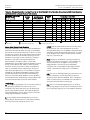
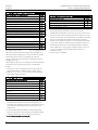
Table 1.3. ANSI/UL1066 Ratings
Interrupting Rating Tier ANSI/UL1066 Devices, LVPCB
Type
240V
480V
600V
1/2S
Withstand
N
65,000
65,000
65,000
65,000
H
85,000
85,000
65,000
65,000
E
85,000
85,000
85,000
85,000
M
100,000
100,000
85,000
85,000
B
100,000
100,000
100,000
100,000
L
150,000
150,000
100,000
100,000
Envelope 1
400-2000
Envelope 2
3200
400-3200
X
X
Table 1.4. UL489 Ratings
Interrupting Rating Tier UL489 Devices, ICCB
Envelope 1
Type
240V
480V
600V
1/2S
400-2000
Withstand
N
65,000
65,000
65,000
42,000
X
H
85,000
85,000
65,000
50,000
X
M
100,000
100,000
85,000
65,000
L
150,000
150,000
100,000
85,000
Envelope 3
3200
4000-5000
X
X
X
X
X
X
X
X
Envelope 2
2500-3000
4003000
X
X
X
Table 1.5. Non-Automatic Circuit Breaker – ANSI Version Ratings
Envelope
Type
Amps
Rated
Interrupting
Minimum Mechanical
Current
Endurance
1
N
800
42
12,500
1
N
1600
42
12,500
1
N
2000
42
12,500
2
M
3200
65
5,000
3
B
4000
100
5,000
3
B
5000
100
5,000
3000
X
Envelope 3
4000 50006000
X
X
X
X
Rated Endurance
Minimum Electrical
Endurance at 480V
10,000
10,000
7,500
5,000
3,000
2,000
Minimum Electrical
Endurance at 600V
7,500
7,500
5,000
5,000
2,000
1,500
Table 1.6. Non-Automatic Circuit Breaker/Molded Case Switch – UL Version Ratings
Envelope
Type
Amps
Short
Rated Endurance
Interrupting
Minimum Mechanical
Minimum Electrical
Current
Endurance
Endurance at 480V
1
N
800
42
12,500
10,000
1
N
1600
42
12,500
10,000
1
N
2000
42
12,500
7,500
2
M
3000
65
5,000
5,000
3
B
4000
100
5,000
3,000
3
B
5000
100
5,000
3,000
3
B
6000
100
5,000
1,500
Minimum Electrical
Endurance at 600V
7,500
7,500
5,000
5,000
2,000
1,500
1,000
• GE internal quality testing requirements exceeded 20,000 mechanical and electrical operations.
• GE internal quality testing requirements exceeded 20,000 mechanical and electrical operations.
Altitudes and Closing Times
See Section 7, Tables 7.2 and 7.3.
Dimensions and Weights
See Section 7.
2
® 2009 General Electric All Rights Reserved
DET-653A
02 Apr 09
EntelliGuard® G Circuit Breaker Application Guide
Section 2. Features and Characteristics
EntelliGuard® G Power Circuit Breaker
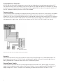
Section 2. Features and Characteristics
Figure 2.1. EntelliGuard G Features and Characteristics
® 2009 General Electric All Rights Reserved
3
DET-653A
02 Apr 09
EntelliGuard® G Circuit Breaker Application Guide
Section 2. Features and Characteristics
STANDARD AND OPTIONAL FEATURES
Short Time Rating
Up to 100kA for 1/2sec.
Short Circuit/High Interruption Rating
150kA at 600V, 100kA at 690V.
Thermal Performance
ANSI C37 and UL 489 designs are 100% rated up to 40ºC when
applied in recommended enclosure sizes. IEC 60947 versions are
100% rated in free air up to 50ºC. IP31 enclosure/switchboard
rating is based on size, recommended up to 50ºC ambient with
rear vertical bus connection (Table 2.1).
Table 2.1. Sensors Available
Standard
Envelope 1
ANSI/UL
400 - 2000
UL 489
400 - 2000
IEC
400 - 2000
Envelope 2
400 - 3200
400 - 3000
400 - 4000
Envelope 3
3200 - 5000
3200 - 6000
3200 - 6400
Reverse Feed
EntelliGuard G devices can be fed from top or bottom terminals.
Two-Step Stored Energy Mechanism
EntelliGuard G operates via stored energy mechanisms that can
be manually charged (MO) or electrically charged (EO) by the
Spring Charging Motor. Closing time is less than five cycles.
Closing and opening can be initiated remotely or via the front
cover push buttons. An Open-Close-Open cycle is possible
without recharging. The breaker operating mechanism is a tripfree mechanism and is furnished with an integrated anti-pumping
system.
Field Installable Trip Units and Accessories
Field-installable accessories are common to all breaker envelopes
and frames.
Coils
EntelliGuard G devices have provisions for four accessory
operating coils. The four positions can be filled by the following
four devices: one Close Coil (CC or CCC), one Shunt Trip Coil, one
UVR (Under Voltage Release), and the fourth position can either
be a Shunt Trip Coil or a UVR. The closing coil is a “one-shot”
electronic closed circuit. Shunt trip (ST) coils are continuous rated.
Under voltage relays (UVR) are available with a fixed time delay
(50ms at down to 50% system voltage; 20ms below 50% system
voltage). The time delay module (TDM) is available as a shippedloose accessory for remote installation (in equipment). Optional
status contact modules for the ST, CC and UVRs provide coil
status (energize/de-energize) via the secondary disconnects and
trip unit.
Breaker/Main Contact Status
OPEN/CLOSED, ON/OFF indication is provided on the front cover.
Motor Operator
Heavy duty, motor/gearbox unit; easily accessible
Ready to Close Indicator
Provides visible indication/readiness for close operation.
4
® 2009 General Electric All Rights Reserved
DET-653A
02 Apr 09
EntelliGuard® G Circuit Breaker Application Guide
Section 2. Features and Characteristics
Mounting Straps/Accessories
Kits are available to mount and connect fixed/stationary
breakers.
Auxiliary Switches (Optional)
Four available designs:
• Power rated (3NO+3NC)
• Power rated (3NO+3NC) + low signal (Hi-Fi) (2NO+2NC)
• Power rated (8NO+8NC)
• Power rated (4NO+4NC) + low signal (Hi-Fi) (4NO+4NC)
Interlocks
Standard interlocks include:
• Drawout Breaker: prevents the breaker from being closed
unless it is in the TEST or CONNECT positions
• Drawout Breaker/Main Contacts: prevents withdrawal/removal
of the breaker unless the main contacts are OPEN. Access to the
drawout mechanism racking screw is blocked when the breaker
is CLOSED.
• Spring Discharge Interlock: Automatically discharges the
closing springs when the breaker is moved from the TEST to the
DISCONNECT position. This prevents withdrawing a breaker from
the cubicle with the closing springs charged.
Breaker Status Indicators
Standard Indicators include:
• The breaker status indicator shows the condition of the main
contacts (OPEN, CLOSED).
• The status of the closing springs is indicated as CHARGED or
DISCHARGED.
• The draw-out position indicator displays whether the breaker is
in the CONNECT, TEST or DISCONNECT position.
• The breaker also includes a switch that provides main contact
status indication to the POWER LEADER™ Power Management
System.
• The optional Reduced Energy Let-Through (RELT) is provided
with an ON/OFF contact closure to positively indicate whether the
RELT setting is enabled or not.
Rejection Feature
A factory-installed rejection feature prevents mismatching
breakers and cassettes/substructures. This prevents (a) inserting
a breaker with a lower interrupting rating into a higher rated
cassette/substructure and (b) inserting a higher current rated
breaker into a lower rated cassette/substructure.
® 2009 General Electric All Rights Reserved
5
DET-653A
02 Apr 09
EntelliGuard® G Circuit Breaker Application Guide
Section 2. Features and Characteristics
Through-Door Racking
The breaker racking mechanism is accessible through the front
door and permits safely disconnecting/withdrawing the circuit
breaker without opening the door and exposing personnel to live
parts during the process.
Padlocking Devices
The padlocking device is standard on breakers and allows up to
three padlocks with 1/4" to 3/8" diameter shanks to secure the
breaker in the OPEN/TRIP FREE position. A padlock provision on
the front panel of the cassette/substructure permits locking the
breaker in either the TEST or DISCONNECT position with up to
three padlocks.
Key Interlock
Up to four optional key interlocks are available (Kirk, Ronis,
Profalux, Castell). Switch gear applications utilize a Kirk key
interlock mounted in the cassette. A maximum of two key
interlocks may fit in the cassette.
Shutters
Optional lockable shutters are available (factory installed).
Carriage Position Switch
This optional cassette/substructure device permits local or
remote indication of the circuit breaker status (CONNECTED, TEST,
DISCONNECTED), 2NO/2NC single pole, double throw contacts are
available for each position.
Lifting Truck
Optional lifting tool with separate slings is available for all breaker
sizes.
IP Covers
Optional IP54 covers (protected against harmful amounts of dust
and splashing water) are available for all breaker sizes.
Mechanical Counter
Provides local record of the cumulative number of complete
breaker closing operations.
Cable Interlocks (OEM Applications Only)
Available for fixed and draw-out breakers, these units enable
direct interlocking of EntelliGuard G circuit breakers.
Bell Alarm Contact
Available with or without a mechanical lockout feature, the bell
alarm operates whenever the breaker trips due to a protective
function (electrical fault).
6
® 2009 General Electric All Rights Reserved
EntelliGuard® G Circuit Breaker Application Guide
Section 3. EntelliGuard TU Trip Unit System
DET-653A
02 Apr 09
EntelliGuard G Power Circuit Breaker
Section 3. EntelliGuard TU Trip Unit System
EntelliGuard TU series trip units are available as the
standard controller for new production EntelliGuard G
ANSI/UL 1066, UL 489 and IEC circuit breakers. EntelliGuard
TU designs are also available as direct, functional
replacements for GE's PowerBreak, PowerBreak II, WavePro,
AKR, and AK circuit breakers. EntelliGuard TU trip units are
also available in kit form for many popular non-GE and older
GE low voltage power circuit breakers (Refer to DEH-4567).
New, on-board features and communications capabilities
enable equipment enhancements, improved operational
performance and life extension programs. Performance will
vary based on associated circuit breaker and equipment
conditions.
This section describes the functions as implemented in the
EntelliGuard G UL 489 and ANSI/UL 1066 circuit breakers.
References or comparisons to other GE circuit breakers are
for informational purposes only.
Reliability without Compromising Protection
Reliable protection of circuits and equipment has always
been the circuit breaker’s primary mission. Providing
appropriate protection of the conductors, while preserving
selective coordination, has been the primary focus of most
system designers. However, what was acceptable in the
past is no longer the standard today.
Modern economic reality, coupled with strict regulatory
requirements, demand optimal system performance with
increased sensitivity to the inherent power system hazards
that face operating and maintenance personnel. Safety
agencies, local authorities and owner-operators demand
better personnel protection and state-of-the-art capabilities
to minimize hazards while simultaneously preserving critical
loads and system capabilities.
These requirements often seem to be, and sometimes are, in
conflict, pitting the speed and sensitivity required to improve
arc flash protection against the delays and deliberate
decision making required to maximize power system
reliability. The EntelliGuard TU, along with the EntelliGuard
family of circuit breakers, offers flexible solutions for
demanding circuit protection and circuit preservation
environments. The EntelliGuard TU is designed to provide the
utmost in system protection and reliability simultaneously,
with little or no compromise.
® 2009 General Electric All Rights Reserved
Arc Flash and the EntelliGuard TU Trip Unit
Reducing arc flash hazard is a primary concern in many
power system designs. The best way to ensure the lowest
possible hazard for a particular distribution system is to
consider the hazard as the system is designed and make
careful selection of the system’s topology, circuit sizes,
equipment sizes and protective devices to minimize hazard
for the operating and maintenance personnel that will need
to use the system for years to come.
The EntelliGuard TU, especially in conjunction with the
EntelliGuard G circuit breaker, provides significant flexibility
towards solving arc flash hazard problems without
excessive sacrifice of system reliability, in terms of
selectivity.
One way to lower potential incident energy is to ensure that
circuit breakers are able to interrupt using their
Instantaneous trips for all expected arcing faults. Figure 3.1
shows the expected arcing currents for 480V systems for
various arc gaps representative of switchgear (32mm),
switchboards (25mm), MCCs (25mm) and panelboards
(13mm). These values were determined using IEEE standard
1548, Guide for Performing Arc-Flash Hazard Calculations,
2002.
Figure 3.1. Arcing Current
50.0
40.0
kA Arcing
Introduction
The EntelliGuard TU Trip Unit offers optimum circuit
protection and optimum system reliability simultaneously
with little or no compromise to either of these critical
functions. Reliability and arc flash protection, in one
package, at the same time, all the time.
30.0
32mm
20.0
25mm
13mm
Box
10.0
Open
0.0
10
20
30
40
50
60
70
80
90
100
kA Available
Figure 3.1 demonstrates the wide range of possible arcing
currents predicted by the IEEE standard’s calculations. The
actual arcing currents may be lower or higher when
consideration is given to the potential error in short circuit
calculations, fault current data provided by the utility
company, and variance in the actual arcing gap or
enclosure’s geometry where the arc occurs. Of particular
concern should be the lower end of the possible range of
current that may fall below the Instantaneous pickup of a
circuit breaker or the current limiting threshold of a fuse.
Dangerous incident energy may quickly increase when
interruption time increases from a few cycles to a few
seconds, even for low arcing current.
7
EntelliGuard® G Circuit Breaker Application Guide
®
Section 3. EntelliGuard TU Trip Unit System
DET-653A
02 Apr 09
Selectivity with Molded Case Circuit Breakers and Other
Devices
The EntelliGuard TU trip unit’s adjustable selective
instantaneous provides a unique selectivity capability. When
used in conjunction with current limiting devices
downstream, the trip unit may be set low, and still maintain
significant levels of selectivity. Table 3.1 lists the minimum
instantaneous setting above specific GE circuit breakers and
the levels of selectivity achieved. Testing and documentation
of the selectivity capability of the EntelliGuard Trip unit will
be expanded as more test data becomes available. Always
consult GE Selectivity reference publication DET-537 for the
latest information or contact your GE sales representative
for up to date information.
instantaneously for faults within their zone of protection
allows significant selectivity and arc flash protection at the
same time.
Selectivity for an EntelliGuard TU ground fault function and a
circuit breaker below may be enhanced by the trip unit’s
selective ground fault function and zone selective
interlocking. Figure 3.2 demonstrates an 800A circuit
breaker under a 1200A ground fault set to be fully selective.
See also Tables 3.2 and 3.3.
Figure 3.2. Selectivity Curve
Selectivity above current limiting fuses may also be
expected. The required minimum setting may be estimated
by examining the peak let-through curve for the fuse. Find
the peak let-through current value that is 1.41 times the
prospective RMS current. The trip unit should be set such
that the instantaneous pickup is above that peak value. The
circuit breaker and fuse may then be selective up to the
values identified in Table 3.1. The fuse and circuit breaker
combinations have not been tested so performance cannot
be guaranteed at this time; however, selectivity is expected
for arcing and bolted faults up to the values indicated in the
above selectivity table.
Protection between circuit breakers using the EntelliGuard
TU trip unit may be further improved using zone selective
interlocking. The trip unit’s unique instantaneous zone
selective interlocking which can increase selectivity for UL
489 EntelliGuard G mains while allowing to trip
Table 3.1. EntelliGuard Selectivity Above GE Current Limiting Circuit Breakers
Load Side Device
Frame
Maximum Trip
Record Plus G
Record Plus E
Record Plus B/C
Spectra G
Spectra F
Spectra E
600A
250A
100A
600 A
250A
150A
Line Side Device with EntelliGuard TU Trip Unit
Minimum Adjustable
Selective Instantaneous
Nominal Pickup in Amps
at 208V to 480V
20800A
10000A
7200A
30000A
18400A
18400A
PowerBreak II,
UL 489 CB
WavePro or
AKR, ANSI
CB
EntelliGuard
G, UL 489 CB
EntelliGuard
G, ANSI CB
Up to Short
Circuit Rating;
65kA, 100kA
and 150kA at
480V and
200kA at 240V
Up to Short
Circuit
Rating; 65kA
and 100kA at
480V
Up to
Withstand
Rating; 42kA,
50kA, 65kA, or
85kA at 480V
Up to
Withstand
Rating; 65kA,
85kA, 100kA at
480V
• Instantaneous selectivity between any other GE load side non-current-limiting circuit breaker and a line side circuit breaker with an EntelliGuard TU trip
unit is verified via traditional time current curves. It may also be calculated by taking the maximum instantaneous setting of the upstream device, adjusted
by its negative tolerance (-9.09%).
• Any instantaneous curve overlap seen between above CBs when the line side trip unit is set per the table does not indicate a lack of selectivity.
8
® 2009 General Electric All Rights Reserved
EntelliGuard® G Circuit Breaker Application Guide
Section 3. EntelliGuard TU Trip Unit System
DET-653A
02 Apr 09
Table 3.2 Maximum Selectivity Above Non Current
Limiting CB
Frame
Rating
Plug
UL 489 EntelliGuard G CBs with Some
Nominal Rating Plug Sizes
N
H
M
L
400
5,455
5,455
5,455
800
800
10,909
10,909
10,909
1200
16,364
16,364
16,364
1600
1600
21,818
21,818
21,818
2000
2000
27,273
27,273
27,273
3000
3000
35,455
40,909
40,909
40,909
4000
4000
54,545
54,545
5000
5000
54,545
68,182
6000
6000
54,545
70,909
• Selectivity is calculated by multiplying the nominal instantaneous
pickup setting in X times the rating plug and dividing by 1.1. The
nominal instantaneous pickup setting in amperes cannot exceed
95% of the circuit breaker's claimed withstand rating.
Table 3.3. Maximum Selectivity Above Non Current
Limiting CB
Frame Max. UL 1066 EntelliGuard G CBs with Some Nominal Rating
Rating
Plug Sizes and Instantaneous Off
Plug
N
H
E
M
B
L
800
800
65,000
59,540
85,000
77,860
1600
1600
65,000
59,540
85,000
77,860
2000
2000
65,000
59,540
85,000
77,860
3200
3200
65,000
85,000
77,860
100,000 91,600
4000
4000
85,000
77,860
100,000 91,600
5000
5000
85,000
77,860
100,000 91,600
85,000
85,000
100,000 100,000
Withstand
Rating
65,000
65,000
• Selectivity with instantaneous on is calculated by multiplying the
nominal Instantaneous pickup setting in X times the rating plug
and dividing by 1.1. The nominal instantaneous pickup setting in
amperes cannot exceed 95% of the circuit breaker's claimed
withstand rating.
Above Downstream Feeders
The EntelliGuard TU trip unit has Short Time bands under
100msec designed to optimally fit above the Instantaneous
clearing times of various GE circuit breakers. Table 3.4 lists
the suggested Short Time band that may be used above
specific GE circuit breakers for the fastest coordination and
consequently fastest EntelliGuard G circuit breaker
interruption.
® 2009 General Electric All Rights Reserved
Also listed is the Hazard Risk Category for various available
fault currents calculated at the listed Short Time band
clearing times and Instantaneous clearing times provided by
the EntelliGuard TU trip unit’s Adjustable Selective
Instantaneous and its Reduced Energy Let-Through (RELT)
Instantaneous trip. The Hazard Risk Category (HRC) levels
shown are calculated for a solidly grounded, 480V system,
32mm arc gap, 18 in. working distance and arc in box. Using
the optimized Short Time band allows the system to stay at
HRC2 most of the time and always less than HRC4. However,
use of the RELT Instantaneous trip allows the system to
protect at HRC1 or 2 for available fault currents as high as
90kA.
The Adjustable Selective Instantaneous
The Instantaneous algorithm in the EntelliGuard TU trip unit
will allow a large switchboard or switchgear circuit breaker
to be set low yet maintain selectivity. For example, when set
to protect the conductors to a motor control center, an 800A
feeder circuit breaker’s Instantaneous may be set as low as
8kA nominal. This should provide complete selectivity above
the typical 150A and smaller circuit breakers or fuses found
in a motor control center.
Allowing for 10% pickup tolerance in the Instantaneous
pickup of the feeder circuit breaker would indicate that the
feeder would pickup Instantaneously for arcing fault
currents approximately 9kA or higher. From Figure 3.1 it can
be seen that fault currents of 20-25kA and higher would
seem to reliably produce arcing current above 9kA in a
variety of configurations. From Table 3.4 it can be seen that
an EntelliGuard G circuit breaker clearing instantaneously
can maintain HRC1 in a system with up to 42kA available
and HRC2 in systems with up to 100kA available – excellent
arc flash protection and selectivity simultaneously!
Note: These incident energy calculations do not take into
account motor contribution or other factors that may affect
expected levels of incident energy or hazard. For a thorough
understanding of the incident energy available or HRC in a
power distribution system, an Arc Flash Study should be
conducted by engineering personnel qualified to provide
such analysis.
9
EntelliGuard® G Circuit Breaker Application Guide
®
Section 3. EntelliGuard TU Trip Unit System
DET-653A
02 Apr 09
Table 3.4. Minimum Selective Clearing Times for an EntelliGuard G Circuit Breaker Above Selected GE Circuit Breakers,
and Related HRC Levels at Various Fault Circuits
GE Molded Case Circuit
Breaker Family
FB, FC, TEY, THQL
TED, TEC
TF, TJ, TK
Spectra E, F, G Frame
Spectra K Frame
Spectra G, K with MVT trip
Record Plus G Frame
Record Plus E Frame
Power Break with MVT
Instantaneous Clearing Time
RELT Clearing Time
TM = Thermal Magnetic.
E = Electronic.
Circuit
Breaker
Type
Minimum
EntelliGuard TU
Short Time Band
Clearing
Time
TM, LP
TM-GP, MCP
TM-GP
E-GP
E-GP
AE-GP
E, AE-GP
E-GP
AE-GP
-
0.025sec
0.025sec
0.025sec
0.025sec
0.033sec
0.025sec
0.042sec
0.033sec
0.058sec
instantaneous
RELT Instantaneous
0.08sec
0.08sec
0.08sec
0.08sec
0.088sec
0.08sec
0.097sec
0.088sec
0.113sec
0.050sec
0.042sec
AE = Adjustable Electronic.
LP = Lighting Panel Application.
480V, 32mm, 24in Working Distance,
Arc in a Box - HRC @ Ibf=
35kA 42kA 50kA 60kA 75kA 90kA 100kA
2
2
2
2
3
3
3
2
2
2
2
3
3
3
2
2
2
2
3
3
3
2
2
2
2
3
3
3
2
2
2
2
3
3
3
2
2
2
2
3
3
3
2
2
2
2
3
3
3
2
2
2
2
3
3
3
2
2
2
3
3
3
3
1
1
1
2
2
2
2
1
1
1
1
2
2
2
GP = General Purpose Application.
MCP = Motor Circuit Protector).
Above Other Power Circuit Breakers
Using the EntelliGuard TU trip unit’s unique Instantaneous
Zone Selective Interlocking (ZSI), the main circuit breaker
also can be set to interrupt selectively for faults in its zone
of protection. However, the pickup level must be nested to
prevent a nuisance trip at the main. Allowing for a 10%
tolerance in the pickup current of both trips, the upper
boundary of the main’s trip may be estimated at
approximately 11kA. Again, Figure 3.1 shows that
available fault currents above 25kA will generally produce
arcing currents above 11kA. Table 3.4 shows a system
with fault currents from 35kA to 100kA, the feeder and
main circuit breaker will provide protection at HRC1 or
HRC2 selectively above most circuit breakers using short
time bands. Coordinated instantaneous settings would
provide even better protection while still maintaining
selectivity with select feeder breakers. To this capability
one can add the RELT instantaneous setting that provides
more sensitive and faster protection when needed.
Terminology
In: Trip plug rating in amperes. This is the current rating of
the rating plug installed in the trip unit. This is the
maximum Long Time pickup a trip unit can have with a
specific plug installed. A sensor can usually be applied
with plugs between 37.5% or 40% to 100% of the sensor
rating. Plugs are labeled in amperes.
HRC = Hazard Risk Category (See NFPA 70E.
HSIOC: High Set Instantaneous Overcurrent, also known
as the Override. This is an Instantaneous protection
setting applied near the circuit breaker’s withstand rating
required to clear high magnitude faults quickly. In UL489
circuit breakers this is fixed; in UL1066 CBs the override
may vary, if present at all.
MCR: Making Current Release. A setting provided with
each trip unit, based on the specific circuit breaker size,
used to protect the circuit against closing on high
magnitude faults. The MCR function immediately
trips/opens the circuit breaker if high magnitude fault
current is sensed at the instant the circuit breaker is
closed.
ICW: Short Circuit Withstand Rating of a particular circuit
breaker in amperes. The withstand rating is defined
differently within different standards, but it is always the
value of current that a circuit breaker can withstand for
some period of time without interrupting.
ICU: Short Circuit Interrupting Rating (ISC), or ultimate
interrupting rating (ICU) in IEC terms. The maximum shortcircuit interrupting rating of a circuit breaker in amperes.
X: X is a multiplier that may be applied in front of any
rating value to denote a fraction of that rating. Example:
The Long Time Pickup may be set at 0.5X of In.
10
® 2009 General Electric All Rights Reserved
EntelliGuard® G Circuit Breaker Application Guide
Section 3. EntelliGuard TU Trip Unit System
DET-653A
02 Apr 09
Figure 3.3. Thermal Characteristic: Maximum and
Minimum Long Time Delay Bands for a 1000A Long Time
Pickup
1,000.00
100.00
22 Time Delay Bands
10.00
Seconds
Long Time Protection
The EntelliGuard TU offers two different shapes for Long
Time protection curves. Each type of curve is available with
22 different time delays. The shapes may be described as
thermal type I2t characteristics and fuse shaped I4t lines.
The nominal Long Time pickup is computed from the trip
rating plug value (In) multiplied by the Long Time pickup
setting. Long Time pickup setting multipliers are user
settings and may range from 0.5 to 1.0 in increments of 0.05.
The actual Long Time pickup is 112% of the nominal setting
(Ir). 112% is to compensate for the Long Time Pickup
Tolerance of ±10% that is drawing as “actual value/1+
tolerance)”. For a nominal 1000A Long Time pickup, the
actual trip setting is 1120A, drawn as a vertical band
between 1120/1.1 and 1120/0.9, or 1018A and 1244A.
1.00
Thermal Long Time Overcurrent
2
The thermal I t shape is similar to the typical curve of a
thermal magnetic circuit breaker and matches the shape of
many overcurrent devices used in industry today. The typical
shape and range of settings may be seen in Figure 3.3. The
range of time delays is shown in Table 3.5 at various
multiples of nominal (100%) current setting. Drawn bands
also include a mechanical constant time to account for
circuit breaker operating and clearing time, which causes
the slight widening of the band evident at the lower (right)
end of the faster (lower) bands.
0.10
0.01
10
1,00
10,000
100,000
Amperes
Table 3.5. Thermal Characteristic: Nominal Clearing and Commit Times for X Multipliers of Nominal Pickup
X=
Min CB
C-2
C-3
C-4
C-5
C-6
C-7
C-8
C-9
C-10
C-11
C-12
C-13
C-14
C-15
C-16
C-17
C-18
C-19
C-20
C-21
Max CB
1.5
Commit
4.25
12.7
25.5
34.0
51.0
67.9
84.9
102
119
136
153
170
204
238
272
306
340
374
408
442
476
510
7.2
Clear
8.04
24.1
48.1
64.1
96.2
128
160
192
224
256
289
321
385
449
513
577
641
705
769
833
898
962
Commit
0.139
0.417
0.83
1.11
1.67
2.22
2.78
3.33
3.89
4.44
5.00
5.56
6.67
7.78
8.89
10.0
11.1
12.2
13.3
14.4
15.6
16.7
10
Clear
0.239
0.656
1.28
1.70
2.53
3.4
4.2
5.0
5.9
6.7
7.5
8.4
10.0
11.7
13.4
15.0
16.7
18.4
20.0
21.7
23.4
25.1
Commit
0.072
0.215
0.430
0.57
0.86
1.15
1.43
1.72
2.01
2.29
2.58
2.87
3.44
4.01
4.59
5.16
5.73
6.30
6.88
7.45
8.02
8.60
12
Clear
0.137
0.352
0.674
0.89
1.32
1.75
2.18
2.61
3.03
3.46
3.89
4.32
5.18
6.04
6.90
7.76
8.61
9.47
10.3
11.2
12.0
12.9
Commit
0.050
0.149
0.298
0.40
0.60
0.79
0.99
1.19
1.39
1.59
1.79
1.99
2.38
2.78
3.18
3.58
3.97
4.37
4.77
5.17
5.56
5.96
15
Clear
0.104
0.253
0.476
0.62
0.92
1.22
1.52
1.81
2.11
2.41
2.71
3.00
3.60
4.19
4.79
5.38
5.98
6.57
7.17
7.76
8.36
8.95
Commit
0.038
0.095
0.190
0.254
0.38
0.51
0.63
0.76
0.89
1.02
1.14
1.27
1.52
1.78
2.03
2.29
2.54
2.79
3.05
3.30
3.56
3.81
Clear
0.080
0.172
0.315
0.410
0.60
0.79
0.98
1.17
1.36
1.55
1.74
1.93
2.31
2.69
3.07
3.45
3.83
4.21
4.59
4.97
5.35
5.73
• Algorithm will not commit below 1.5 cycles, clearing time will not be less than 0.08sec.
• Maximum LT curve is 15XLTPU for Envelope 1 and 2 devices, 10XLTPU for Envelope 3 devices.
• Actual Long Time pickup is 112% of nominal pickup.
® 2009 General Electric All Rights Reserved
11
EntelliGuard® G Circuit Breaker Application Guide
®
Section 3. EntelliGuard TU Trip Unit System
DET-653A
02 Apr 09
Fuse-Shaped Steep Long Time Overcurrent
The optional steeper fuse characteristic is a straight line
K=I4t shape for application in systems where fuses and
circuit breakers are used together. Twenty-two different
time bands are available in each trip unit.
Figure 3.4. Fuse Characteristic: Maximum and Minimum
Long Time Delay Bands for a 1000A Long Time Pickup
1,000.00
Figure 3.4 displays minimum and maximum bands. Table 3.6
displays the nominal time delays for each of the 22 bands at
various multiples of nominal current pickup.
100.00
Drawn bands also include a 30 ms constant time, which
accounts for the slight widening evident in the time current
curve at the lower (right) end of the faster (lower) time bands.
Seconds
10.00
22 Time Delay Bands
1.00
0.10
0.01
10
1,00
10,000
100,000
Amperes
Table 3.6. Fuse Characteristic: Nominal Clearing and Commit Times for X Multipliers of Nominal Pickup
X=
Min Fuse
F-2
F-3
F-4
F-5
F-6
F-7
F-8
F-9
F-10
F-11
F-12
F-13
F-14
F-15
F-16
F-17
F-18
F-19
F-20
F-21
Max Fuse
1.5
Commit
0.675
1.96
3.56
5.57
8.07
11.2
15.1
20.0
26.1
33.8
43.3
55.3
70.2
88.9
112
141
178
224
280
352
441
540
7.2
Clear
1.51
4.37
7.95
12.4
18.0
25.0
33.7
44.7
58.3
75.4
96.7
123
157
198
251
316
397
499
626
785
984
1204
Commit
0.025
0.025
0.025
0.025
0.025
0.025
0.028
0.038
0.049
0.064
0.082
0.104
0.132
0.167
0.211
0.266
0.335
0.421
0.528
0.663
0.830
1.017
10
Clear
0.080
0.080
0.080
0.080
0.080
0.080
0.080
0.084
0.110
0.142
0.182
0.232
0.295
0.374
0.472
0.595
0.748
0.940
1.179
1.479
1.853
2.269
Commit
0.025
0.025
0.025
0.025
0.025
0.025
0.025
0.025
0.025
0.025
0.025
0.028
0.036
0.045
0.057
0.072
0.090
0.113
0.142
0.178
0.223
0.273
12
Clear
0.080
0.080
0.080
0.080
0.080
0.080
0.080
0.080
0.080
0.080
0.080
0.080
0.080
0.100
0.127
0.160
0.201
0.252
0.317
0.397
0.498
0.610
•
Algorithm will not commit below 1.5 cycles, clearing time will not be less than 0.08sec.
•
Maximum LT curve is 15XLTPU for Envelope 1 and 2 devices, 10XLTPU for Envelope 3 devices.
Commit
0.025
0.025
0.025
0.025
0.025
0.025
0.025
0.025
0.025
0.025
0.025
0.025
0.025
0.025
0.027
0.035
0.043
0.055
0.068
0.086
0.108
0.132
15
Clear
0.080
0.080
0.080
0.080
0.080
0.080
0.080
0.080
0.080
0.080
0.080
0.080
0.080
0.080
0.080
0.080
0.097
0.122
0.153
0.192
0.240
0.294
Commit
0.025
0.025
0.025
0.025
0.025
0.025
0.025
0.025
0.025
0.025
0.025
0.025
0.025
0.025
0.025
0.025
0.025
0.025
0.028
0.035
0.044
0.054
Clear
0.080
0.080
0.080
0.080
0.080
0.080
0.080
0.080
0.080
0.080
0.080
0.080
0.080
0.080
0.080
0.080
0.080
0.080
0.080
0.080
0.098
0.120
• Actual Long Time pickup is 112% of nominal pickup.
12
® 2009 General Electric All Rights Reserved
EntelliGuard® G Circuit Breaker Application Guide
Section 3. EntelliGuard TU Trip Unit System
DET-653A
02 Apr 09
Figure 3.5. Short Time Pickup
1,000.00
100.00
10.00
Seconds
Thermal Memory
The Long Time and Short Time pickup algorithm also
includes a cooling cycle that keeps track of current if it
oscillates in and out of pickup range. This Thermal Memory is
also active in case the circuit breaker trips on Long Time or
Short Time to account for residual heating in conductors. If a
circuit breaker is closed soon after a Long Time trip or Short
Time trip, a subsequent trip may happen faster than
indicated by the time current curve due to the residual cable
Thermal Memory effect. In trips without control power, the
Thermal Memory is powered from the Trip Unit battery. The
cooling algorithm requires up to 14 minutes to fully reset to
zero.
1.00
Short Time Protection
1X
STPU
1.5-12X
or
1.5-10X
Short Time Pickup
An example of this may be seen in Figure 3.5 for the
combination of Long Time Delay Band and Short Time Delay
Band shown in Figure 3.6, any Short Time pickup setting
larger than 6X will result in the Long Time band intersecting
with the horizontal Short Time delay band rather the vertical
Short Time pickup.
0.10
0.01
10
1,00
10,000
100,000
Amperes
Figure 3.6. Short Time Transition
1,000.00
100.00
10.00
Seconds
The EntelliGuard TU provides a wide range of Short Time
pickup settings, I2t characteristics and time bands to
optimize selectivity while not sacrificing clearing time
unnecessarily. Short Time pickup settings range from 1.5 to
12 times the Long Time pickup setting for the EntelliGuard G
circuit breakers in Envelopes 1 and 2. The maximum Short
Time pickup for Envelope 3 is 10. In Power Break, WavePro,
AKR and other circuit breakers, the maximum Short Time
pickup may be lower. The transition between Long Time
band and Short Time function may happen at the horizontal
Short Time Delay Band rather than the vertical Short Time
pickup, depending on the following:
• How fast or what type of Long Time band is chosen
• What Short Time pickup is selected
• What Short Time Delay is selected
Transition to STPU
1.00
Transition to ST TDB
Short Time Bands
The EntelliGuard TU comes with a wide range of adjustable
Time Delay Bands, ranging from a minimum of 25ms (clears
in 80ms) to 417ms (clears in 472ms). The bands are specially
designed to pickup above various circuit breakers and trip
systems to provide required selectivity while not sacrificing
any more clearing time than required to provide the best
possible arc flash protection.
0.10
0.01
10
1,00
10,000
100,000
Amperes
The time bands are shown in Table 3.7 and Figure 3.7.
® 2009 General Electric All Rights Reserved
13
EntelliGuard® G Circuit Breaker Application Guide
®
Section 3. EntelliGuard TU Trip Unit System
DET-653A
02 Apr 09
Figure 3.8. Short I2t (In or Out)
Label
Minimum
2nd
3rd
4th
5th
6th
7th
8th
9th
10th
Maximum
Pickup
0.025
0.033
0.042
0.058
0.092
0.117
0.158
0.183
0.217
0.350
0.417
Clearing
0.080
0.088
0.097
0.113
0.147
0.172
0.213
0.238
0.272
0.405
0.472
Figure 3.7. Short Time Delay
1,000.00
100.00
10.00
Maximum I2t
Same as MicroVersaTrip
Seconds
Table 3.7. Short Time Delay Bands
Maximum I 2t
Slope Up to 10X of
ST Pickup
1.00
Intermediate I2t
0.10
1,000.00
Minimum I2t
0.01
100.00
10
1,00
10,000
100,000
Amperes
The maximum (upper) Short Time I2t band may not be used
with the minimum Long Time thermal band. Use of the fuse
shaped Long Time bands also inhibits use of the Short Time
I2t bands. Only the definite time Short Time pickup
characteristic may be used with the fuse shaped Long Time
curves.
Seconds
10.00
1.00
Short Time Delay Bands
11 Available
0.025 – 0.417Sec. commit
0.10
0.01
10
1,00
10,000
100,000
Amperes
Short Time I2t Slopes
The EntelliGuard Trip Unit offers three different Short Time I2t
characteristics to allow optimized settings for selectivity and
fast protection whenever possible. When using the
EntelliGuard Trip Unit in systems that also employ older GE
MVT trip units, the EntelliGuard Trip Unit’s maximum I2t
characteristic is equal to the Short Time I2t characteristic in
the MVT trip.
The position of the I2t slopes varies with the Long Time
pickup of the respective circuit breaker. The intersection of
the Short Time pickup and the Short Time delay band with
the I2t slope varies with the Short Time pickup and time delay
band.
The three positions for the Short Time I2t band are shown in
Figure 3.8. The bands may be defined by the formula K = I2t,
where K equals 18, 8 and 2 times the nominal Long Time
pickup squared. A 30msec fixed time is added to account for
circuit breaker mechanical operation, clearing time and
variance. Pickup tolerance is 10% of current.
14
Ground Fault Protection
The EntelliGuard TU trip unit offers the ultimate in Ground
Fault protection. Each trip unit may be provided with the
ability to accept a neutral sensor signal and generate an
internal Zero Sequence phasor for Ground Fault protection.
It may also be equipped with the ability to accept a Zero
Sequence phasor signal from an external Zero Sequence CT
or residual summation scheme using current transformers.
Either Ground Fault method may be used to provide Ground
Fault trip or Ground Fault alarm. Four pole circuit breakers
may also provide Ground Fault protection based on an
external Zero Sequence input signal or a residual sum of all
four internal sensors.
Internal Residual Summation
The EntelliGuard TU trip unit uses internal air core sensors
for current sensing, and the signals are residually summed
using advanced digital electronics. A neutral sensor may be
located remotely and connected to the trip unit. The
connection is limited to 10m (33ft). Due to the air core
sensor’s ability to handle a wide range of primary currents
without distortion, Ground Fault sensing is accurate for a
wide range of phase and current inputs.
® 2009 General Electric All Rights Reserved
EntelliGuard® G Circuit Breaker Application Guide
Section 3. EntelliGuard TU Trip Unit System
DET-653A
02 Apr 09
External Zero Sequence Input
The EntelliGuard TU trip unit is able to accept input from an
externally calculated Ground Fault current. The Ground Fault
current may be derived using a single Zero Sequence CT or
multiple phase CTs connected in a residual summation
scheme. External CE marked Zero Sequence or ground
return CTs are available for IEC applications, but are not UL
Listed. Phase CTs used for a summation connection are UL
Listed. Applications for this capability include sensing at the
ground return connection for a transformer or generator as
well as application in multiple source grounded systems.
Ground Fault Pickup Settings
All UL 489 and UL 1066 circuit breakers are limited to a
maximum nominal pickup setting of 1200A per the National
Electrical Code or 60% of the sensor size, whichever is lower.
The minimum setting is 20% of sensor size. The available
maximum settings per sensor may be seen in Table 3.8.
Ground Fault Protection Curves
The EntelliGuard TU trip unit offers four different shapes for
the ground fault function:
• Definite time with adjustable time delay.
2
• I t slope with adjustable time delay.
4
• I t slope (fuse shaped) with adjustable time delay.
2
• Selective double break I t with adjustable time delay.
The definite time and I2t characteristics provide the
traditional GF curve shapes. The I4t characteristic provides a
shape more in line with downstream fuses. GE’s unique
selective double break I2t characteristic provides the most
selective setting possible while still meeting the applicable
UL and NEC standards. In many cases, an 800A circuit
breaker may be used under a 1200A ground fault curve
selectively (Fig. 3.9).
Figure 3.9. Ground Fault Characteristics
1,000.00
Table 3.8. Ground Fault Time Delay Bands
Minimum
0.2
0.2
0.2
0.2
0.2
0.2
0.2
0.2
0.2
0.2
0.2
0.2
Maximum
0.60
0.60
0.60
0.60
0.60
0.60
0.48
0.40
0.37
0.30
0.24
0.20
Ground Fault Time Delay Bands
Ground Fault Time Delay Bands used in the EntelliGuard G
circuit breakers range from 42msec to 942msec. In Power
Break I, Power Break II, WavePro and AKR circuit breakers,
the minimum GF Time Delay Band is 58msec and the
maximum is 417msec.
The available minimum settings per circuit breaker type are
shown in Table 3.9. The maximum Time Delay Band setting
for all circuit breakers is 0.940sec with a 1sec clear.
Table 3.9. Minimum Ground Fault Pickup and Clear Time
Setting
Power Break I & II,
AKR & WavePro
EntelliGuard G
Minimum pickup
0.058sec
0.042sec
Minimum clear
0.113sec
0.097sec
Maximum pick
0.417sec
0.940sec
Maximum clear
0.470sec
1.000sec
® 2009 General Electric All Rights Reserved
1200A
NEC Maximum
100.00
SGF
10.00
Seconds
Sensor
400
600
800
1200
1600
2000
2500
3000
3200
4000
5000
6000
3000A, 1Sec.
NEC point
Point
1.00
I2t
I4t
0.10
0.01
1,000
10,000,,000
Amperes
10,000
10,000
100,000
100,000
Instantaneous Protection
The EntelliGuard TU trip unit may provide several types of
Instantaneous protection, depending on the circuit breaker
in which it is installed. The different types of Instantaneous
protection are as follows:
• Adjustable Selective Instantaneous: Provided on Power
Break II, WavePro, AKR and EntelliGuard G.
• Extended Range Adjustable Selective Instantaneous: An
available option on ANSI EntelliGuard G circuit breakers.
• High Set Instantaneous Overcurrent Trip: Provided on
Power Break II and some EntelliGuard G circuit breakers,
also called an override.
• Making Current Release (MCR): Provided on all EntelliGuard
G circuit breakers.
• Reduced Energy Let-Through Instantaneous Trip: An
available option on Power Break II, WavePro, AKR and
EntelliGuard G circuit breakers.
15
EntelliGuard® G Circuit Breaker Application Guide
®
Section 3. EntelliGuard TU Trip Unit System
DET-653A
02 Apr 09
Each of these Instantaneous trips provides optimum
protection, selectivity or both as required for different
applications, subject to the capabilities of the respective
circuit breakers in which the trip units are installed.
Adjustable Selective Instantaneous
The EntelliGuard TU uses an exclusive algorithm, developed
by GE, to recognize the wave shape of fault current within a
cycle. With the improved analysis of the fault current wave
shape, the trip unit allows the circuit breaker to trip
immediately yet provide superior selectivity when used
above current limiting circuit breakers or fuses. In many
cases, the trip unit’s Instantaneous pickup may be set quite
low yet allow for complete selectivity up to the circuit
breaker’s full withstand level. For a list of possible selective
combinations of GE circuit breakers employing the
EntelliGuard TU trip unit and various downstream
overcurrent devices, see GE publication DET-536.
The EntelliGuard TU trip unit can be furnished with one of
two Instantaneous adjustment ranges. The standard
adjustable range may be as high as 15X the trip plug value
on all UL 489 or UL 1066 circuit breakers. An optional
Extended Range Adjustable Selective Instantaneous, as high
as 30X, may be provided for UL 1066 Listed Low Voltage
Power Circuit Breakers (LVPCBs). LVPCBs also allow for this
adjustable Instantaneous trip to be turned off. The minimum
adjustable Instantaneous pickup setting for all circuit
breakers is 2X the trip plug rating. The available maximum
pickup settings are described in Table 3.10. The maximum
Instantaneous pickup is limited by the circuit breaker’s
withstand rating.
Table 3.10. Maximum Adjustable Instantaneous Pick-up for EntelliGuard G Circuit Breakers with Normal or Extended
Range Option
Withstand Rating
“In” (Plug
Rating, A)
42
50
65
100
Extended
Normal
Extended
Normal
Extended
Normal
Extended
Normal
Extended
Range
Range
Range
Range
Range
Range
Range
Range
Range
Range
150-2,000
15
N/A
15
N/A
15
30
15
30
15
30
2,200
N/A
N/A
15
N/A
15
28
15
30
15
30
2,400
N/A
N/A
15
N/A
15
25
15
30
15
30
2,500
N/A
N/A
15
N/A
15
24
15
30
15
30
3,000
N/A
N/A
15
N/A
15
20
15
26
15
30
3,200
N/A
N/A
N/A
N/A
15
19
15
25
15
29
3,600
N/A
N/A
N/A
N/A
15
17
15
22
15
26
4,000
N/A
N/A
N/A
N/A
15
15
15
20
15
23
5,000
N/A
N/A
N/A
N/A
N/A
N/A
15
16
15
19
6,000
N/A
N/A
N/A
N/A
N/A
N/A
13
N/A
N/A
N/A
The Adjustable Selective Instantaneous will clear a fault in
three cycles when used in 60Hz or 50Hz applications. Zone
Selective Interlocking (ZSI) may be used with this
Instantaneous function, allowing several breakers with
overlapping Instantaneous protection to be selective with
each other. Because each circuit breaker is set to trip
Instantaneously for faults within their respective zones of
protection, fast protection and selectivity are achieved
simultaneously.
16
85
Normal
The special selective Instantaneous algorithm allows any
circuit breaker above current limiting devices to be set with
a relatively low Instantaneous pickup and still achieve
significant selectivity. The system may be able to provide
Instantaneous protection for most faults, including high
impedance arcing fault, while maintaining significant levels
of selectivity. Figures 3.11 and 3.12 later in this document
demonstrate the performance of the Instantaneous ZSI
capability.
® 2009 General Electric All Rights Reserved
EntelliGuard® G Circuit Breaker Application Guide
Section 3. EntelliGuard TU Trip Unit System
DET-653A
02 Apr 09
High Set Instantaneous Overcurrent (HSIOC)
The EntelliGuard TU trip unit’s HSIOC pickup is similar to the
fixed override used by other trip units and circuit breakers in
the industry. In EntelliGuard G, the HSIOC setting is changed
automatically by the trip unit if the normal adjustable
Instantaneous is turned off (LVPCB only). When adjustable
Instantaneous setting is turned off, HSIOC nominal setting
becomes 98% of the circuit breaker’s Short Time withstand
setting. In all other cases, in the EntelliGuard G family of
circuit breakers, the HSIOC is set high enough to allow full
selectivity up to the circuit breaker’s short time withstand
rating.
For circuit breakers with a HSIOC trip function, the location
of the HSIOC trip is shown by the line that reaches the
0.01sec axis at the bottom of the TCC. The location of that
line is shown in Table 3.11. In many applications, the
EntelliGuard G circuit breaker with an EntelliGuard TU trip
unit will be completely selective up to the HSIOC pickup or
the circuit breaker’s full short circuit rating, even with the
adjustable Instantaneous on.
Making Current Release (MCR)
This form of Instantaneous protection is provided on all
EntelliGuard G circuit breakers. This function provides
protection in case the circuit breaker is closed on an
unusually high current. A circuit breaker that experiences 15
times (15x) or more its plug rating is possibly closing in on a
fault caused by incorrectly wired conductors, forgotten
grounding cables or some other type of unusual low
impedance fault.
Alternatively, it is closing on a very low impedance arcing
fault. In either case, there is a possibility that equipment may
be damaged by the high fault current or an arc flash hazard
has been inadvertently created. The MCR provides very fast
protection when the circuit breaker is closed and for the first
six cycles thereafter. After the six cycles have elapsed, the
MCR is turned off and the circuit breaker reverts to its
adjustable Instantaneous pickup and HSIOC if provided. The
MCR will clear fault current in 40msec or less.
Table 3.11. HSIOC Locations
Short
Circuit Tier
N
H
E
M
B
L
•
240V
65,000
85,000
85,000
100,000
100,000
150,000
480V
65,000
85,000
85,000
100,000
100,000
150,000
Interrupting Rating (A)
600V
65,000
65,000
85,000
85,000
100,000
100,000
UL489 ICW
42,000
50,000
N/A
65,000
N/A
85,000
UL1066 ICW
65,000
65,000
85,000
85,000
100,000
100,000
UL489
Override
42,000
50,000
N/A
65,000
N/A
85,000
UL1066
Override
None
65,000
None
85,000
None
10,000
All UL Overrides are -0% tolerance, ANSI Override pickup at -0% or -9% based on Adjustable Selective Instantaneous being on or off.
Reduced Energy Let-Through (RELT) Instantaneous Trip
The EntelliGuard TU trip unit provides an optional second,
user-adjustable, RELT Instantaneous trip. This trip provides
an alternate Instantaneous setting that allows a user to
temporarily set a circuit breaker to a more sensitive pickup
to provide better protection, only when better protection is
needed and some selectivity may be sacrificed. The RELT
pickup is adjustable from 1.5X to 15X of plug rating,
independently of the normal adjustable selective
Instantaneous. It may be set higher or lower than the
selective Instantaneous.
The user must make two entries at the trip unit: (1) Pickup
settings (1.5-15X of the plug) and (2) ON, OFF or REMOTE.
ON/OFF enables or disables the pickup setting. REMOTE
allows the RELT Instantaneous pickup to be enabled via
application of 24Vdc or Vac at the RELT input terminals or
serial communications via the Modbus or Profibus
communication port. The RELT pickup may be enabled via
serial communication or remote 24V signal, but both need
to be indicating “OFF” for the RELT Instantaneous pickup
to be disabled. The RELT input command may be wired to
a manual switch, automatic sensor or, via external logic,
to one or more signal sources.
® 2009 General Electric All Rights Reserved
When the EntelliGuard TU trip unit has the RELT
Instantaneous pickup enabled, the trip unit provides a
feedback signal via an optically isolated dry contact and
serial communication. This provides positive feedback that
the trip unit has received and reacted to the RELT Enable
command.
The EntelliGuard TU trip unit’s RELT capability provides the
ultimate in user flexibility for wiring and controlling an
alternate Instantaneous setting for temporary use to reduce
personnel hazard. The RELT Instantaneous pickup clears
fault current in 42msec or less at 60Hz.
RELT capability may be provided on a trip unit with or
without control power. If 24V is provided to the RELT input,
the trip unit will use the RELT Instantaneous trip setting.
However, without control power connected to the trip unit
permanently, indication that the trip unit is in the RELT mode
may not be reliably communicated. If reliable
communication that the trip unit is in the RELT mode is
desired, it is suggested that the trip unit be permanently
connected to 24Vdc control power.
17
EntelliGuard® G Circuit Breaker Application Guide
®
Section 3. EntelliGuard TU Trip Unit System
DET-653A
02 Apr 09
Reduced Energy Let-Through Switch Wiring
The RELT switch may be connected to a manually operated
two-position switch, a remote sensor, or both
simultaneously. The EntelliGuard TU trip unit provides a
feedback capability directly from the trip so the user is able
to verify that the signal was received by the trip unit and the
settings have changed. Optionally, an indicating light may
also be connected to the source of control power so the user
knows if control power is available to change the setting.
The trip unit does not require its own control power to
accept a RELT input and change the Instantaneous trip
pickup according to the user settings. However, if control
power is available to the trip unit, the feedback signal will
function immediately, rather than when the trip unit
becomes self-powered through its load current (Fig. 3.10).
Figure 3.10. Integrated Switch and LED, Spring Return
from “Test” to “Off,” Latched in “On”
LED
Test
ON
EntelliGuard
Trip Unit
24
VDC/VAC
RELT Input
RELT Output
• This configuration provides positive indication that the trip unit has
received and processed the RELT "On" signal. It Also provides a control
power check. Caution: It is recommended that RELT output be wired to
an appropriate annunciation when remote activation control of RELT is
used.
NOTE: When using the RELT function in conjunction with
remote enable/disable control, it is strongly recommended
that the trip unit be provided with permanently connected
control power and that the RELT status output be assigned
to a trip output contact. The trip output contact should be
wired to appropriately located annunciation. The trip unit will
accept a command to enable the RELT instantaneous pickup
setting via local HMI control, a 24Vac/dc voltage applied at
the input terminals or serial communication. Regardless how
the enable command is received, the trip unit will be in the
RELT mode when protection is required. However, the status
indicating contacts will only close if the trip unit is powered
through the internal current transformers or 24Vdc control
power. Lack of 24Vdc control power could provide unreliable
indication of RELT status due to low load conditions on the
circuit breaker.
18
Zone Selective Interlocking (ZSI)
The EntelliGuard TU trip unit’s ZSI capability differs from that
found in other circuit breaker trips in two significant ways:
1. It allows independent and separate settings of the
unrestrained (in zone protection) and the restrained
(back up protection) bands.
2. It provides simultaneous and independent ZSI of both
the Short Time and Instantaneous protection. This
allows each circuit breaker to zone interlock with upper
tier circuit breakers between ST band to ST band,
Instantaneous to Instantaneous, or Instantaneous to
Short Time.
The EntelliGuard TU trip unit's fast ZSI system is able to
interlock Ground Fault, Short Time and Instantaneous. When
required for feeder selectivity the main is able to be set
faster than the feeder without any sacrifice in selectivity. As
long as the main breaker's pickup is set above the feeder's
pickup the two devices will remain selective. Each circuit
breaker in a ZSI scheme allows separate user settings for
the restrained (backup) and unrestrained (in zone
protections) for ground fault and short time protection. For
the lowest tier device in the scheme the restrained and
unrestrained are set to the same values. For instantaneous
protection there is only on pickup setting required.
Instantaneous protection may also be interlocked such that
all circuit breakers above the one whose zone has the fault
will shift from Instantaneous clearing to a 0.058msec time
band. Since it is expected that faults of sufficient magnitude
to engage the Instantaneous pickup are dangerously high,
all zone selective interlocked Instantaneous trips that
receive a restraint signal are shifted to the same band.
Should the bottom circuit breaker fail to clear for whatever
reason, quick back up protection from both ties and feeders
is provided.
Short Time and Ground Fault bands for zone interlocked
circuit breakers may be set to any band available to the trip.
Figure 3.11 shows two circuit breakers set to protect at their
unrestrained settings. Figure 3.12 shows the same two
circuit breakers while a fault is detected below the lower
circuit breaker in the system and after a restraint signal is
received by the upper circuit breaker’s trip unit. The upper
circuit breaker’s Short Time band has shifted from the user
setting of 0.025sec to a user set restrained band of 0.092sec.
The Instantaneous has shifted from the adjustable selective
Instantaneous band clearing in 0.050sec to the fixed
restrained band of 0.058sec, clearing in 0.113sec. This allows
the lower circuit breaker to clear faults within their zone of
protection above 7,000A RMS and 11,000A RMS respectively,
clearing under 100msec, while maintaining full selectivity for
faults up to 85,000A.
® 2009 General Electric All Rights Reserved
EntelliGuard® G Circuit Breaker Application Guide
Section 3. EntelliGuard TU Trip Unit System
DET-653A
02 Apr 09
Figure 3.11. Zone Selective Interlocked CB, Upper CB
Shown “Unrestrained”
1,000.00
100.00
The EntelliGuard TU trip rating plugs are unique in that they
can be used with multiple trip units and circuit breakers
within a specific sensor range, rather than only with a single
specific sensor. The trip rating plug catalog number, shown
in Figure 3.13, identifies the rating as well as the minimum
and maximum sensor rating the plug may be used with.
Table 3.12 lists trip rating plugs available for each sensor.
Table 3.13 lists the two-digit codes used within the trip rating
plug catalog numbers and the sensor current ratings to
which they are mapped.
10.00
Seconds
Figure 3.13. EntelliGuard Trip Unit Rating Plug Catalog
Number Guide
Unrestrained Settings
1.00
0.10
0.01
100
1,000
10,000
100,000
Amperes
Figure 3.12. Zone Selective Interlocked CB, Upper CB
Shown “Restrained”
1,000.00
100.00
10.00
Seconds
Restrained Settings
1.00
ST TDB Shift
0.10
Adjustable Selective
Instantaneous Shift
0.01
100
1,000
10,000
100,000
Universal Trip
Rating Plugs
The EntelliGuard TU trip system is composed of trip units and
trip rating plugs along with the sensors and wiring provided
in the EntelliGuard G circuit breaker to support the trip.
Rating plugs are used to lower the Long Time adjustment
range of the sensor provided in the circuit breaker.
Amperes
® 2009 General Electric All Rights Reserved
19
EntelliGuard® G Circuit Breaker Application Guide
®
Section 3. EntelliGuard TU Trip Unit System
DET-653A
02 Apr 09
Table 3.12. Trip Rating Plug Specifications
Trip Plug Catalog
Number
Plug
Rating
GTP0060U0101
GTP0080U0102
GTP0100U0102
GTP0125U0102
GTP0150U0404
GTP0200U0404
GTP0225U0406
GTP0250U0407
GTP0300U0408
GTP0350U0408
GTP0400U0410
GTP0450U0612
GTP0500U0613
GTP0600U0616
GTP0700U0816
GTP0750U0820
GTP0800U0820
GTP0900U1020
GTP1000U1025
GTP1100U1225
GTP1200U1232
GTP1500U1640
GTP1600U1640
GTP1900U2050
GTP2000U2050
GTP2200U2550
GTP2400U2564
GTP2500U2564
GTP3000U3064
GTP3200U3264
GTP3600U4064
GTP4000U4064
GTP5000U5064
GTP6000U6064
60A1
1
80A
100A2
125A1
150A
200A
225A
250A
300A
350A
400A
450A
500A
600A
700A
750A
800A
900A
1000A
1100A
1200A
1500A
1600A
1900A
2000A
2200A
2400A
2500A
3000A
3200A
3600A
4000A
5000A
6000A
Table 3.13. Trip Rating Plug Codes
May Be Used With
Minimum
Sensor
150A3
150A3
150A3
150A3
150A3
4
200A
400A
400A
400A
400A
400A
600A
600A
600A
800A
800A
800A
1000A
1000A
1200A
1200A
1600A
1600A
2000A
2000A
2500A
2500A
2500A
3000A
3200A
4000A
4000A
5000A
6000A
Maximum
Sensor
150A3
200A4
200A4
200A4
400A
400A
600A
630A5
800A
800A
1000A
1200A
1250A5
1600A
1600A
2000A
2000A
2000A
2500A
2500A
3200A
4000A
4000A
5000A
5000A
5000A
6400A5
6400A5
6400A5
6400A5
6400A5
6400A5
5
6400A
6400A5
Sensor Designation
01
02
04
06
07
08
10
12
13
16
20
25
30
32
40
50
60
64
Sensor Rating
150A1
200A2
400A
600A
630A3
800A
1000A
1200A
1250A3
1600A
2000A
2500A
3000A
3200A
4000A
5000A
6000A
6400A3
1 Sensor available in WavePro and AKR only.
2 Sensor available in Power Break only.
3 Sensor available in IEC listed circuit breaker only.
Table 3.14 lists the plugs available for each sensor in the
various circuit breakers in which the EntelliGuard TU may be
installed.
1 WavePro & AKR only. EntelliGuard G min. trip plug is 150A.
2 PowerBreak only. EntelliGuard G min. trip plug is 150A.
3 WavePro & AKR only. EntelliGuard G min. sensor is 400A.
4 PowerBreak only. EntelliGuard G min. sensor is 400A.
5 IEC only sensor, UL equivalents are 600A.
20
® 2009 General Electric All Rights Reserved
EntelliGuard® G Circuit Breaker Application Guide
Section 3. EntelliGuard TU Trip Unit System
DET-653A
02 Apr 09
Table 3.14. EntelliGuard G Rating Plug Logic (UL 489, UL 1066, IEC)
Breaker Frame/Sensor (A)
All
400
150
200
225
250
300
350
400
UL/ANSI
600
225
250
300
350
400
450
500
600
IEC
630
250
300
350
400
450
500
600
630
All
800
300
350
400
450
500
600
630
700
750
800
All
1000
400
450
500
600
630
700
750
800
900
1000
UL/ANSI
1200
450
500
600
630
700
750
800
900
1000
1100
1200
IEC
1250
500
600
630
700
750
800
900
1000
1100
1200
1250
All
1600
600
630
700
750
800
900
1000
1100
1200
1250
1500
1600
Universal Spare Trip Unit
EntelliGuard G circuit breakers will accept a Universal Spare
Trip Unit. This unique trip unit may be used in any
EntelliGuard G circuit breaker regardless of frame size,
sensor size, short circuit rating or whether the circuit breaker
is listed under UL 489, ANSI/UL 1066 or IEC 947 standards.
Should any circuit breaker’s trip unit fail to operate for any
reason, this one universal trip unit may be used as a
replacement.
Once an EntelliGuard TU trip unit, including the Universal
Spare Trip Unit, is associated with a specific EntelliGuard G
circuit breaker, it may only be used with that specific circuit
breaker. If swapping between EntelliGuard G circuit breakers
is required, a trip unit may only be swapped between circuit
breakers with equal sensor ratings, short circuit ratings and
standard listing. Before the circuit breaker may be used with
a swapped or new trip unit, the trip unit must be mapped to
the circuit breaker.
® 2009 General Electric All Rights Reserved
All
2000
750
800
900
1000
1100
1200
1250
1500
1600
1900
2000
All
2500
1000
1100
1200
1250
1500
1600
1900
2000
2200
2400
2500
UL
3000
IEC/ANSI
3200
1200
1250
1500
1600
1900
2000
2200
2400
2500
3000
1200
1250
1500
1600
1900
2000
2200
2400
2500
3000
3200
All
4000
1500
1600
1900
2000
2200
2400
2500
3000
3200
3600
4000
All
5000
1900
2000
2200
2400
2500
3000
3200
3600
4000
5000
UL/IEC
6000
IEC
6400
2400
2500
3000
3200
3600
4000
5000
6000
2400
2500
3000
3200
3600
4000
5000
6000
6400
The mapping procedure is described in the trip unit
instruction book and requires that control power be
provided to the trip unit from permanently connected
control power or a portable power supply that may be
connected via the trip unit’s front test and communication
connection.
Universal Trip Units may be ordered with a limited set of
options. It is suggested that they be ordered with the widest
range of options used within a facility, as any unnecessary
functions can always be disabled or turned off (except for
Ground Fault) during set up by the user. The user-selected
options for the Universal Trip Unit are listed in Table 3.15.
21
EntelliGuard® G Circuit Breaker Application Guide
®
Section 3. EntelliGuard TU Trip Unit System
DET-653A
02 Apr 09
Table 3.15. Universal Spare Trip Unit Options
(User-Selected)
Feature
Long Time
Instantaneous
Ground Fault
Arc Flash
Protection
Zone Selective
Interlocking
Communications
Metering
#
1
2
1
2
1
2
3
1
2
1
2
1
2
3
1
2
3
Relay Functions
The EntelliGuard TU offers various protective and alarm relay
functions that may be displayed on the LCD screen,
assigned contact outputs or communicated serially (Table
3.16).
Option
Standard
Standard and Fuse
Standard
Extended Range
None
Standard
Ground Input
No RELT
RELT
Short Time and Ground Fault
Short Time, Ground Fault and
Instantaneous
None
Modbus
Profibus
Standard (ammeter)
Advanced (A, V, E and P)
Diagnostic (Advanced and WFC)
Protective Relays
Protection relays may be set by the user to alarm, trip the
circuit breaker or both. Alarms and trips are displayed on the
local LCD trip and communicated serially. Alarms may also
be assigned to one of two output contacts. The Trip Alarm
settings are independently set for each relay function.
Voltage-Unbalance Relay
This function compares the highest or lowest phase voltage
with the average of all three phases and initiates a trip if the
difference exceeds the set point. The true RMS voltage is
computed for each phase (Table 3.17).
Table 3.17. Voltage Unbalance Settings
• Mains and ties in solidly grounded multiple source substations will
Setting
Voltage
unbalance pickup
Voltage
unbalance delay
usually require ground input type ground fault protection. Feeders will
use standard internal ground fault protection.
Option
Adjustable from 10% to 50% in
increments of 1%.
User adjustable from 1sec to 15sec in
increments of 1sec. Setting this value to
zero (0) will disable the relay.
Table 3.16. Relay Functions Available in EntelliGuard G Circuit Breakers with EntelliGuard TU Trip Units
Metering
Diagnostics
Status
Protective
Functions
Voltage Unbalance
Under Voltage
Over Voltage
Current Unbalance
Power Reversal
Current Level Alarm, 2 Settings Available
Health Indication (Bad)
Health Indication (Good)
RELT ON Status3
Ground Fault Alarm Status
ZSI Output
Trip Target
Trip Information
Trip Counter
Event Logging (Trips, Alarms, I/O)
Waveform Capture
Current (Phases A, B, C, N)
Voltage (Phase A, B, C)1
Energy (kWh, Total)
Real Power (Watts, Per Phase and Total)
Apparent Power (Watts, Per Phase and Total)
Reactive Power
1 User set to PH-N or PH-PH.
22
Trip
Alarm
Display
Output
Contact 2
Serial
Comm.
yes
yes
yes
yes
yes
yes
yes
yes
yes
yes
yes
yes
yes
yes
yes
yes
yes
yes
yes
yes
yes
yes
yes
yes
yes
no
no
no
no
no
no
yes
yes
yes
no
no
no
yes
yes
yes
yes
yes
yes
yes
yes
yes
yes
yes
yes
yes
yes
yes
yes
yes
yes
no
no
yes
no
yes
no
no
yes
no
yes
no
no
yes
no
yes
no
no
yes
no
yes
no
no
yes
no
yes
no
no
yes
no
yes
no
no
no
no
no
no
no
no
no
no
yes
yes
yes
yes
yes
no
no
no
no
no
yes
yes
yes
yes
yes
2 Output contacts are low signal (Hi-Fi).
1
X
X
X
X
X
X
X
X
X
X
-
Output3
2
Dedicated
X
X
X
X
X
X
X
X
X
X
-
3 When top unit has RELT, output 1 is dedicated to RELT ON status.
® 2009 General Electric All Rights Reserved
EntelliGuard® G Circuit Breaker Application Guide
Section 3. EntelliGuard TU Trip Unit System
DET-653A
02 Apr 09
Current Unbalance Relay
This function compares the true RMS current in the highest
or lowest phase with the average of all three phases and
initiates a trip if the difference exceeds the set point (Table.
3.18).
Table 3.18. Current Unbalance Settings
Item
Current unbalance
pickup
Current unbalance
delay setting
Options
Adjustable from 10% to 50% in
increments of 1%.
User adjustable from 1sec to 15sec in
increments of 1sec. Setting this value to
zero (0) will disable the relay.
Under Voltage Relay
This function measures the true RMS voltage in all phases
and initiates a trip if any phase voltage drops below the set
point.
Under Voltage Relay Zero-Volt Trip Enable
This function determines if the relay trips when all threephase voltages drop to zero volts. Uses the same timing set
for the Under-Voltage Relay (Table. 3.19).
Table 3.19. Under Voltage Settings
Item
Under voltage
pickup
Under voltage
delay setting
Options
Adjustable from 50% to 90% in
increments of 1%.
User adjustable from 1sec to 15sec in
increments of 1sec. Setting this value
to zero (0) will disable the relay.
Over Voltage Relay
This function measures the true RMS voltage in all phases
and initiates a trip if any phase voltage exceeds the set
point. See Table. 3.20.
Table 3.20. Over Voltage Settings
Item
Over voltage
pickup
Over voltage delay
setting
Options
User adjustable from 110% to 150% in
increments of 1%.
User adjustable from 1sec to 15sec in
increments of 1sec. Setting this value
to zero (0) will disable the relay.
Power-Reversal Relay
This function measures the direction of power flow through
the breaker and initiates a trip if a sufficient magnitude of
reverse power is detected (Table. 3.21).
® 2009 General Electric All Rights Reserved
Table 3.21. Power-Reversal Settings
Item
Power reversal
pickup
Power reversal
delay setting
Options
User adjustable from 10 kW to 1990 kW
in increments of 10 kW.
User adjustable from 1sec to 15sec in
increments of 1sec. Setting this value to
zero (0) will disable the relay.
Power-Direction Setup
This function selects the normal power flow direction for the
breaker, either from line to load or from load to line. This
direction setup also affects the sign of the normal power
metering displays.
Potential Transformer Primary Voltage
Enter the primary voltage rating of the potential transformer.
The range of values is 120V to 600V, in 1V increments.
Potential Transformer Connection
Select the appropriate potential transformer connection,
either line-to-line (Ph-Ph) or line-to-neutral (Ph-N).
Power Demand Intervals
This function sets the power demand interval, which can be
in the range of 5min to 60min, in steps of 5min. This setpoint specifies the time interval for power demand
averaging. The trip unit calculates a rolling average of
breaker power over this time interval.
Current Alarm
The Trip unit provides two types of current alarm: Current
Alarm 1 and Current Alarm 2. The current alarm’s ON/OFF
pickup settings are user adjustable from 0.5 to 1.0 xIn in
steps of 0.05. The trip unit does not allow the current alarm
OFF set-point to be set above the ON threshold. If the
highest measured phase current goes above the current
alarm 1 or current alarm 2 ON set-point, and then remains
above the set-point for more than 60sec, the output will
close if assigned to either of these alarms. If the current falls
below the current alarm 1 or current alarm 2 set-point for
more than 60sec, the output, if assigned to the current
alarm, will open. This is a definite time function with a 60s
delay and a 60sec cool down period. Both periods are fixed.
Trip Logic Inputs
The trip unit is able to receive two hardwired input signals.
Either can be a 24Vac or Vdc signal. The inputs can be
assigned to two main functionalities:
• Reduce Let Thru Energy (RELT) instantaneous protection
“ON”.
• Breaker “TRIP”.
23
EntelliGuard® G Circuit Breaker Application Guide
®
Section 3. EntelliGuard TU Trip Unit System
DET-653A
02 Apr 09
Table 3.22 shows the assignment for the inputs.
Table 3.22. Input Assignments Possible
Input
Assignment
Summary Description
OFF
No action taken.
TRIP
OFF
Will cause the circuit breaker to trip.
Input causes to unit to use the RELT
set-point as long as input is active.
Note: RELT must be set to REMOTE at
the Trip HMI or via serial
communications.
No action taken.
TRIP
Will cause the circuit breaker to trip.
1
RELT
2
Outputs for EntelliGuard G Circuit Breakers
The number of outputs available varies by breaker. The
EntelliGuard G circuit breaker has three. These outputs are
relay contact outputs to secondary disconnect. Each output
can be configured per Table 3.23.
Table 3.23. Output Configuration
Function
GF alarm
Over-current trip (GF,
INST, LT, ST)
RELT on
Any protective relay
Current alarm 1
Current alarm 2
Health status. NO or NC
may be assigned to
Health OK via serial
communication
Summary Description
Closes when GF alarm is activated.
Relays 1 or 2.
Over-voltage trip closes the relay.
Relays 1 or 2.
Closes relay when Reduced Let
Through Energy Instantaneous pickup
setting is enabled. Relays 1 or 2.
Closes relays when protective the relay
is in pickup. Relays 1 or 2.
Exceeding current alarm pick-up
closes relay. Relays 1 or 2.
Exceeding current alarm pick-up
closes relay. Relays 1 or 2.
Relay contact will change state when
the Health Monitoring algorithm
senses a change. Relays 1 or 2.
Waveform Capture
When a fault has taken place, it is important to visualize the
event. The Waveform Capture option included in the
advanced trip unit can track and visualize any fault event.
The device tracks eight cycles, four before and four after the
event, with resolution of 48 samples per cycle at 60Hz and
stores the results in memory. It registers events in all three
phases and the neutral. After the event, the waveform is
stored in COMTrade format and can be accessed by using
the waveform client module of the Enervista software. When
the upload into this software is complete, the tripuUnit will
reset this function and be available to register the next
event.
EntelliGuard Trip Unit Summary
Table 3.24 provides an overview of the trip unit features,
characteristics and Specifications and accuracy.
Performance Characteristics Graphs
Figure 3.14 through 3.17 depict selected sensor
performance characteristics.
Table 3.24. EntelliGuard Trip Unit Summary
Feature
Protection Curves
Neutral
Long Time PU (Ir) and Delays
Short Time Pick and Delays
Instantaneous Protection
24
Characteristic
I2T Slopes
I4t Slopes
IEEE MV (2)
IEC MV (2)
Neutral Over Current Protection
Pick Up Range
I2t Range Delays at 6 X
I4t Range Delays at 6 X
Long Time Thermal Memory
Pick Up Range
ST Delay Band Range (Commit Time)
Band Width
ST Delay Bands
I2T Slopes
2
I T Adjustment
Adjustable IPU Range (3)
Extended Range Adjustable IPU
Making Current Release
Override
Alternate IPU with Remote Enable
Selective Instantaneous
Specification
22
22
no
no
yes
0.5-1.0 (0.05 steps x Plug
0.5sec – 22sec
0.004sec – 3.09 sec
yes
1.5-12X
0.025sec - 0.417sec
55msec
11 (UL), 17 (IEC)
3
with LT pick up
1.5-15X & OFF
1.5-30A & OFF
yes
yes
yes (RELT IPU)
yes
® 2009 General Electric All Rights Reserved
EntelliGuard® G Circuit Breaker Application Guide
Section 3. EntelliGuard TU Trip Unit System
DET-653A
02 Apr 09
Table 3.24. EntelliGuard Trip Unit Summary (continued)
Feature
Ground Fault Protection
Zero Selective Interlock
Characteristic
Pick Up Range
External Zero Seq. (Gnd Return) CT
Input
Delay Band Range
Delay Bands
I2t Slopes
I4t Slopes
GF Alarm Option
Short time
Ground Fault
Separate ZSI Band Settings
Instantaneous
Current Unbalanced
Over Voltage
Under Voltage
Protective Relays
Voltage Unbalance
Power Reversal
Metering, Diagnostic, and
Miscellaneous Functions
Serial Comm.
I/O
Flexibility
Current Level (Alarm/Load
Management)
Current (A)
Voltage (V)
Real Power (kW)
Reactive Power (KVAr)
Apparent Power (kVA)
Energy (KWh)
Frequency (Hz)
Real Demand (kW)
Power Factor (%)
Peak Power Demand (KW)
Waveform Capture (COMTrade)
Trip Operations Counter
Temperature Monitoring
Event Log
Open Protocols (13)
Front Port for Local Comm
Programmable Relays
Health Monitoring Relay
Universal Trip Plugs (16)
Adjustable (20%-100%) Trip Plug
Universal Spare Trip Unit
Interchangeable Trip Unit
® 2009 General Electric All Rights Reserved
Specification
0.1/0.2 – 10
1A = 100%
Accuracy (at 100%)
-
0.042/0.058-0.417/0.0917sec
9/7/2015
2
1
yes
yes
yes
yes
yes
10% - 50% difference between highest
& lowest phase compared to average,
1% steps; 1 to 15sec delay in 1sec
steps
110% - 115% of line voltage in 1%
Steps; 1-15sec delay in 1sec steps
30% - 85% of line voltage in 1% Steps;
1-15 Second Delay in 1 sec steps
10% - 50% difference between highest
& lowest phase compared to average,
1% steps; 1 to 15sec delay in 1sec
steps
Line to Load OR Load to Line, From 10
to 990kW in 10kW steps
2
2%, ±0.1sec on delay
A, B, C & neutral
A, B, & C
A, B, C and total
A, B, C and total
A, B, C and total
A, B, C and total
yes
total
A, B, C
A, B, C
yes (requires PMCS)
yes
future
last 10 events
Modbus RTU, Profibus DP
yes – standard
4
1
yes
yes
yes
with = sensor & process
2%, ±0.1sec on delay
2%, ±0.1sec on delay
2%, ±0.1sec on delay
2%
0000 Resolution, 2%
0000 resolution, 2%
000.000 resolution, 4%
000.000 resolution, 4%
000.000 resolution, 4%
000.000 resolution, 4%
00 resolution, 1 cycle
000.000 resolution, 4%
00 resolution, 4%
000.000 resolution, 4%
-
25
DET-653A
02 Apr 09
EntelliGuard® G Circuit Breaker Application Guide
®
Section 3. EntelliGuard TU Trip Unit System
Figure 3.14. Long Time Circuit Breaker Characteristics
26
® 2009 General Electric All Rights Reserved
DET-653A
02 Apr 09
EntelliGuard® G Circuit Breaker Application Guide
Section 3. EntelliGuard TU Trip Unit System
Figure 3.15. Short-Time Pickup and Delay Bands
® 2009 General Electric All Rights Reserved
27
DET-653A
02 Apr 09
EntelliGuard® G Circuit Breaker Application Guide
®
Section 3. EntelliGuard TU Trip Unit System
Figure 3.16. Ground Fault: Multiple of Sensor
28
® 2009 General Electric All Rights Reserved
DET-653A
02 Apr 09
EntelliGuard® G Circuit Breaker Application Guide
Section 3. EntelliGuard TU Trip Unit System
Figure 3.17. Instantaneous, Override (HSIOC), Reduced Energy Let-Through Instantaneous (RELT)
® 2009 General Electric All Rights Reserved
29
EntelliGuard® G Circuit Breaker Application Guide
Section 4. Accessories
DET-653A
02 Apr 09
EntelliGuard® G Power Circuit Breaker
Section 4. Accessories
Introduction
A wide range of optional accessories are interchangeable
across all EntelliGuard G power circuit breakers, regardless
of nominal rating or envelope/frame size. As shown in Figure
4.1, each accessory incorporates easy-fit design features for
quick installation, either at the factory or in the field. NOTE:
Replacement accessories have an “R” at the end of the
catalog number as shown in the tables.
Figure 4.1. Accessory Mounting
Motorized Spring Charging Unit
The unique motor/gearbox unit is specially designed to
operate with the full range of EntelliGuard G breakers. It is
easily installed with three heavy-duty bolts. After a breaker
close operation, the unit automatically recharges the spring
and makes it ready for immediate re-close should the need
arise. High speed recharging ensures that the springs are
fully charged within approximately three seconds following
a release. All electrically operated (EO) ANSI/UL breakers are
equipped with “Spring Charged” contacts for status
indication (Table 4.1).
Circuit Breaker Closing Coils – Standard and Commanded
Two, easy-to-fit, clip-on closing coil options with simple,
plug-in connections are available. Both options offer
electrical remote release of the spring charged closing
mechanism. Both options include a standard anti-pump
safety feature ensuring that the close signal must be
released before further close commands are allowed. The
Command Close Coil additionally provides for local breaker
close and remote breaker close over communications via
the EntelliGuard Trip Unit (Table 4.2).
Table 4.1 Motor Operators
Envelope
Nominal Control IEC Range (85% to 110%)
Voltage
24Vdc/30Vdc
20.4V to 26.4V
48Vdc
40.8V to 52.87V
60Vdc
51V to 66V
DC – 300W
72Vdc
61.2V to 79.2V
110Vdc/130Vdc
106.25V to 137.5V
1
250Vdc
212.5V to 275V
48Vac
40.8V to 52.87V
120Vac
102V to 132V
AC – 350VA
240Vac
204V to 264V
277Vac
235.5V to 304.7V
24Vdc/30Vdc
20.4V to 26.4V
48Vdc
40.8V to 52.87V
60Vdc
51V to 66V
DC – 480W
72Vdc
61.2V to 79.2V
110Vdc/130Vdc
106.25V to 137.5V
2 and 3
250Vdc
212.5V to 275V
48Vac
40.8V to 52.87V
120Vac
102V to 132V
AC – 560VA
240Vac
204V to 264V
27Vac
235.5V to 304.7V
• Spring charge contact is power rated only, as shown below.
•
•
AC Ratings
DC Ratings
•
Voltage
Amps
Voltage
Amps
•
AC21-15A
24V
DC21-15A
•
110-130V
AC23-10A
110-130V
DC21-10A
AC21-10A
250V
DC21-5A
220-240V
AC23-5A
-
30
Power
Consumption
ANSI Range
UL Range
Cat No.
(85% to 110%)
20.4V to 26.4V
GM0124DR
38V to 56V
40.8V to 52.87V
GM01048DR
51V to 66V
GM01060DR
61.2V to 79.2V
GM01072DR
100V to 140V
106.25V to 137.5V
GM0113ODR
200V to 280V
212.5V to 275V
GM01250DR
40.8V to 52.87V
GM01048AR
104V to 127V
102V to 132V
GM01120AR
208V to 254V
204V to 264V
GM01240AR
235.5V to 304.7V
GM01277AR
20.4V to 26.4V
GM0224DR
38V to 56V
40.8V to 52.87V
GM02048DR
51V to 66V
GM02060DR
61.2V to 79.2V
GM02072DR
100V to 140V
106.25V to 137.5V
GM0213ODR
200V to 280V
212.5V to 275V
GM02250DR
40.8V to 52.87V
GM02048AR
104V to 127V
102V to 132V
GM02120AR
208V to 254V
204V to 264V
GM02240AR
235.5V to 304.7V
GM02277AR
Spring charge time = 3sec max.
Recommended fuse amps: contact factory.
Duty cycle = 2/min.
Envelope 1 motors: running VA ~ 300VA; inrush = 2 to 3 times.
Envelope 2 and 3 motors: running VA ~ 450VA; inrush = 2 to 3 times.
® 2009 General Electric All Rights Reserved
EntelliGuard® G Circuit Breaker Application Guide
Section 4. Accessories
DET-653A
02 Apr 09
Table 4.2. Closing Coil Characteristics
Type
Power
Nominal Control
Catalog
Consumption Voltage
DC: 350W,
20 W (sealed)
Closing
Coil
AC: 350W
(inrush),
20W (sealed)
Command
Operated
Closing
Coil
DC: 350W,
20W (sealed)
AC: 350W
(inrush),
20W (sealed)
Number
24Vdc
GCCN024DR
48Vac/dc
GCCN048R
60 to 72Vdc
GCCN060DR
110/130/120Vac
GCCN120R
208Vac
GCCN208AR
220Vdc/240Vac
GCCN240R
250Vdc/277Vac
GCCN277R
24Vdc
GCCC024DR
48Vac/dc
GCCC048R
60 to 72Vdc
GCCC060DR
110/130/120Vac
GCCC120R
208Vac
GCCC208AR
Status Indication Switch (Coil Signaling Contact)
A plug-in module is available to provide status indication via
the secondary disconnects and trip unit. Coil Signaling
Contacts are available for closing coils, shunt trips and under
voltage releases (Table 4.4). Contact is mounted on top of the
Accessory Device. One of the low signal (Hi-Fi) contacts is
always wired to the tip Unit.
Table 4.4. Coil Signaling Contact Module
Type and
Configuration
1 Power rated +
1 Low signal (Hi-Fi)
(1NO contact each)
Command Operation Module
This module energizes the closing coil to cause the breaker
to close whenever control power is applied to the accessory
and when commanded from the breaker trip unit or breaker
front panel push button (electrical closing.)
Shunt Trip
Energizing the shunt trip (ST), via local or remote input, will
instantaneously activate the circuit breaker mechanism,
ensuring a rapid open operation. The shunt trip is
continuously rated and does not require an auxiliary switch
in series with the coil. The shunt trip is a straightforward,
field installable accessory available in wide range of
voltages. See Table 4.3.
Table 4.3. Extended Range Shunt Trip for UL Ground Fault
and ANSI DC Rating Applications.
Nominal Control Voltage
24Vdc
48Vac/dc
70/72Vdc
110Vdc/120 Vac
125 Vdc
208 Vac
240 Vac
250 Vdc/277 Vac
Catalog Number
GSTG024DR
GSTG048R
GSTG072DR
GSTG120R
GSTG125DR
GSTG208AR
GSTG240R
GSTG277R
• Pickup range = 55%-110%.
• Duty cycle = 2/min.
• Inrush = 480A (ac), 480W (dc).
2 Low signal (Hi-Fi)
(1NO contact each)
Cat. No.
6A
6A
0.5A
0.25A
0.1A
0.1A
GCSP1R
AC
DC
120Vac
250Vac
125Vac
250Vdc
125Vac
30Vdc
AC
125Vac
0.1A
GCSP2R
AC
• Duty cycle = 2/min.
• Closing coil inrush = 350VA.
Rating
DC
Under Voltage Release (UVR) with Fixed Time Delay
The UVR instantaneously activates the circuit breaker trip
mechanism when the source voltage drops below the low
voltage threshold. The UVR is also a simple, field installable
device. NOTE: This accessory acts as a permissive; it is a novoltage/no-close device. The circuit breaker cannot be
closed (manually or electrically) unless the undervoltage
release coil is energized above the required threshold. The
undervoltage release with fixed time delay is specifically
intended for applications where a delay period (ride-through)
is required due to potential voltage events. The delays are
50msec when system voltage drops to 50% and 20msec
when system voltage drops below 50% (Table 4.5).
Table 4.5. UVR Operating Characteristics
Power
Consumption
DC: 350W,
2 W (sealed)
AC: 350W
(inrush),
20W (sealed)
Nominal Control
Voltage
24/30Vdc
40Vdc; 48Vac/dc
60Vdc
110/130/120Vac
208Vac
220Vdc/240Vac
250Vdc/277Vac
Catalog
Number
GUVT030DR
GUVT048R
GUVTO60DR
GUVT130R
GUVT208AR
GUVT240R
GUVT277R
• Duty cycle = 2/min.
• Inrush = 350VA (ac), 350W (dc).
• Holding = 60VA (ac), 50W (dc).
• Holding = 60VA (ac), 50W (dc).
® 2009 General Electric All Rights Reserved
31
EntelliGuard® G Circuit Breaker Application Guide
Section 4. Accessories
DET-653A
02 Apr 09
Time Delay Module (TDM) for UVR (Externally Mounted)
The de-energized operation of the Undervoltage release can
be delayed. This optional, externally mounted module has an
adjustable time delay of 0 sec to 3 sec. The device can be
implemented to prevent undesired breaker tripping due to
momentary voltage interruptions and is connected in series
with the Undervoltage release. The time delay is in addition to
the time delay from the breaker mounted UVR accessory. The
time delay module starts counting at 50% of rated voltage
(Fig. 4.2 and Table 4.6).
Ready To Close Contact
These contacts, as shown in Table 4.8, indicate that the
following conditions are met and the circuit breaker can be
closed:
• The circuit breaker is open.
• The closing springs are charged.
• The circuit breaker in not locked/interlocked in open
position.
• There is no standing closing signal.
• There is no standing opening signal.
Figure 4.2. Time Delay Module
Table 4.8. Ready To Close Contacts (1 NO)
Rating
AC
DC
Table 4.6 TDM Characteristics
Nominal Control Voltage
48Vdc
48Vac
60Vdc
125Vdc
120Vac
208Vac
240Vdc
240Vac
250Vdc
277Vac
Catalog No.
GTDM048D
GTDM048A
GTDM060D
GTDM120D
GTDM120A
GTDM208A
GTDM240D
GTDM240A
GTDM250D
GTDM277A
Remote Operation Coil Combination
Each breaker accepts a maximum of four coils in the
combinations shown in Table 4.7. The four positions can be
filled by the following four devices: one Close Coil, one Shunt,
one UVR, and the final fourth position can either be a Shunt
Trip or a UVR. All coils are mounted from the front and snap
onto the mechanism after the fascia is removed.
Table 4.7. Remote Operation Coil Combination
Combination
1
2
3
Coil Position on Fascia (from left)
1
2
3
4
shunt
CC
UV
shunt
shunt
CC
UV
shunt
UV
CC
UV
Description
120Vac
6A
250Vac
6A
125Vdc
0.5A
250Vdc
0.25A
Catalog
Number
high fidelity/secondary
disconnect
power rated/secondary
disconnect
high fidelity/trip unit
GRTC2R
GRTC2R
GRTC1R
GRTC3R
Auxiliary Switches
Auxiliary switches indicate breaker main contact position.
They change their state in the same time sequence as the
breaker main contacts. See Tables 4.9 and 4.10 for available
combinations and ratings, and Tables 4.11 through 4.14 for
contact information.
Table 4.9. Auxiliary Switches
Contact Configuration
Power rated (3NO+3NC)
Power rated (3NO+3NC) + low signal (Hi-Fi)
(2NO+2NC)
Power rated (8NO+8NC)
Power rated (4NO+4NC) + low signal (Hi-Fi)
(4NO+4NC)
Cat. No.
GAUX3R
GAUX5R
GAUX6R
GAUX8R
Table 4.10. Auxiliary Switch Ratings and Secondary
Disconnect Points
Power
Rated
Hi-Fi
Cat. No.
Power rated
(3NO+3NC)
A14 - A25
N/A
GAUX3R
Power rated (3NO+3NC) +
low signal (Hi-Fi)
(2NO+2NC)
A14 - A25
B10 - B13,
B23 - B26
GAUX5R
N/A
GAUX6R
B4 - B11,
B17 - B24
GAUX8R
Contact Configuration
Power rated
(8NO+8NC)*
Power rated (4NO+4NC) +
low signal (Hi-Fi)
(4NO+4NC)*
A14 - A25,
B4 - B13,
B17 - B26
A14 - A25,
B12 - B13,
B25 - B26
*Options are not available for side mounted sec disc blocks.
• High Fidelity refers to gold-plated contacts. Use for signal level outputs
(10mA min to 100mA max., 8Vdc to 30Vdc, 125Vac.
32
® 2009 General Electric All Rights Reserved
EntelliGuard® G Circuit Breaker Application Guide
Section 4. Accessories
DET-653A
02 Apr 09
Table 4.11. Power Rated (3NO/3NC) (Ref Drawing 10099230)
Switch Contact
Normally Open
Secondary
Disconnect
1
2
5
6
9
10
A25
A24
A23
A22
A21
A20
Connector
Switch Contact
Normally Closed
Secondary
Disconnect
Connector
PL1
3
4
7
8
11
12
A19
A18
A17
A16
A15
A14
PL2
Power
Rated
Table 4.12. Power Rated (8NO/8NC) (Ref Drawing 10099228)
Switch Contact
1
2
5
6
9
10
13
14
17
18
21
22
25
26
29
30
Normally Open
Secondary
Disconnect
A25
A24
A23
A22
A21
A20
B26
B25
B24
B23
B22
B21
B20
B19
B18
B17
Connector
PL1
PL3
PL4
PL2
Switch Contact
3
4
7
8
11
12
15
16
19
20
23
24
27
28
31
32
Normally Closed
Secondary
Disconnect
A19
A18
A17
A16
A15
A14
B13
B12
B11
B10
B9
B8
B7
B6
B5
B4
Connector
PL5
PL7
PL8
Power
Rated
PL6
Table 4.13 Power Rated (3NO/3NC) Low Signal (Hi-Fi) (2NO/2NC) (Ref Drawing 10099232)
Switch Contact
Normally Open
Secondary
Disconnect
Connector
Switch Contact
Normally Closed
Secondary
Disconnect
A19
1
A25
3
2
A24
4
A18
5
A23
7
A17
6
A22
8
A16
PL3
9
A21
11
A15
10
13
A20
B26
12
15
A14
B13
14
B25
16
B12
17
B24
19
B11
18
B23
20
B10
® 2009 General Electric All Rights Reserved
PL1
PL2
Connector
PL6
Power
Rated
PL4
Hi-Fi
PL5
33
EntelliGuard® G Circuit Breaker Application Guide
Section 4. Accessories
DET-653A
02 Apr 09
Table 4.14. Power Rated (4NO/4NC) + Low Signal (Hi-Fi) (4NO/4NC) (Ref Drawing 10099234)
Switch Contact
Normally Open
Secondary
Disconnect
1
2
5
6
9
10
13
14
17
18
21
22
A25
A24
A23
A22
A21
A20
B26
B25
B24
B23
B22
B21
25
26
29
30
B20
B19
B18
B17
Connector
Switch Contact
Normally Closed
Secondary
Disconnect
PL1
3
4
7
8
11
12
15
16
19
20
23
24
A19
A18
A17
A16
A15
A14
B13
B12
B11
B10
B9
B8
27
28
31
32
B7
B6
B5
B4
PL2
PL4
PL3
Connector
PL5
Power
Rated
PL6
PL8
PL7
Hi-Fi
• 15A max. current, 440V max.
Circuit Breaker - Key Interlock Facility
This option supplies factory-installed key interlock
mounting provisions (baseplates and mechanism) on the
front of the breaker fascia. Key interlocks ensure that a
circuit breaker cannot be closed unless the dedicated key
has been inserted and secured within the lock. Circuit
breakers accept ready-to-fit interlocking device kits such
as Castell, Ronis, Kirk and Profalux for installation
between related, separate circuit breakers. NOTE: Locks
and keys are not supplied by GE. Please order separately
from your local supplier (Table 4.15 and Figs. 4.3 and 4.4).
• Kirk Key: Type KCAMXXX10S (Extended), KCAMXXX11S
(Withdrawn). S indicates that the key designation (A,B, etc.)
is to be stamped on the lock and the key.
• Ronis: Type 1104B lock with standard key, 1/4 in. turn to
trap the key, compulsory spindle size.
• For drawout breaker applications, key interlocks can be
mounted in the cassette.
Figure 4.3. Breaker-Mounted Key Interlock
Table 4.15. Key Interlocks and Door Interlocks
Description
Baseplate and mechanism for Ronis locks
(breaker mounted)
Baseplate and mechanism for Kirk Key locks
(breaker mounted)
Mechanism for Ronis key cassette interlock
(cassette mounted)
Mechanism for Kirk key cassette interlock
(cassette mounted)
Door interlock (left side)
Door interlock (right side)
Catalog Number
GBRONR
GBKRKR
GCRONR
GCKRKR
GLHD
GRHD
A Key interlock mounting locations
Figure 4.4. Cassette-Mounted Key Interlock
A Key interlock mounting locations
34
® 2009 General Electric All Rights Reserved
EntelliGuard® G Circuit Breaker Application Guide
Section 4. Accessories
DET-653A
02 Apr 09
Carriage Position Switch (TOC)
Available as an option for mounting within the base of the
cassette/substructure, the carriage position switch provides
six single-pole changeover contacts (single pole, double
throw) for local or remote electrical indication of the circuit
breaker status: CONNECTED, TEST and DISCONNECTED. The
DISCONNECTED position is indicated only when minimum
isolating distances between contacts on both the main and
auxiliary circuits have been achieved. This option is in
addition to the mechanical indicators, which are fitted as
standard. When installed, the carriage switch is IP2X
protected. For use with drawout breakers/cassettes Tables
4.16 and 4.17).
Table 4.16. Carriage Position Switches
Switch Configuration
1 NO/NC switch per position
Set of 2 No/NC switches per position
Catalog Number
GCPS1R
GCPS2R
Table 4.18. Mechanical Interlock (Cable/Rod)
Interlock
Type
Number of
Cables
Required
Breaker Type
withdrawable
2 Way –
Type A
2
1 from 3
Type B
6
2 from 3
Type C
6
1 from 3
Way –
Type D
4
fixed
withdrawable
fixed
withdrawable
fixed
withdrawable
fixed
Poles
Catalog
Number
3
4
3
4
3
4
3
4
3
4
3
4
3
4
3
GI2WADR
GI3WADR
GI2FADR
GI3FADR
GI2WBR
GI3WBR
GI2FBR
GI3FBR
GI2WCR
GI3WCR
GI2FCR
GI3FCR
GI2WDTR
GI3WDTR
GI2FDTR
• Contact factory for availability.
Table 4.17. Carriage Position Switch Ratings (Common
NO/NC Contact Configuration)
AC
DC
Ratings
120Vac
250Vac
125Vac
250Vac
6A
6A
0.5A
0.25A
Mechanical Interlocks (Cable/Rod) (OEM Applications
Only)
Available for fixed and draw-out circuit breakers, these units
enable the direct interlocking of EntelliGuard G circuit
breakers, either mounted side-by-side or stacked. The
interlocking mechanisms are connected by a specially
designed cable or rod in a 1 from 2, 1 from 3, and 2 from 3
configuration, and any mix of current ratings/pole
configurations can be accommodated Table 4.18).
Cables
Standard cable lengths are shown in Table 4.19. (Cables
ordered separately. Please contact our technical customer
service department if longer length is required.)
Table 4.19. Cables for Mechanical Interlocks
Meters
1
1.6
2
2.5
3
3.5
4
Length
Inches
39.4
63
78.7
98.4
118.1
137.8
157.5
Catalog Number
GCB1
GCB2
GCB3
GCB4
GCB5
GCB6
GCB7
• Contact factory for availability.
Mechanical interlocks can be fitted to electrical systems and
can link two and/or three circuit breakers. Any nominal
rating, frame size, number of poles or type (fixed pattern or
draw-out) can be interlocked.
® 2009 General Electric All Rights Reserved
35
EntelliGuard® G Circuit Breaker Application Guide
Section 4. Accessories
DET-653A
02 Apr 09
Table 4.20. Interlock Configurations
Typical Circuit
Interlock Configuration
Type A
1 from 2 interlock
2 cable configuration
Interlocking between two circuit breakers
One normal power supply
One generator (emergency) supply
Type B
1 from 3 interlock
6 cable configuration
Interlocking among three circuit breakers
Three power supplies (generator or transformers)
feeding the same busbar but parallel operation is
prevented.
Possible Combinations
B1
B2
O
O
1
O
O
1
B1 can close only if B2 is open.
B2 can close only if B1 is open.
B1
B2
B3
O
O
O
1
O
O
O
1
O
O
O
1
Only 1 of 3 breakers can be closed.
Available on request.
Type C
2 from 3 interlock
6 cable configuration
Interlocking among three circuit breakers
Two bus sections can be powered by single
transformer (bus tie breaker closed) or both
transformers (bus tie breaker open).
Available on request.
Type D
1 from 3 interlock
6 cable configuration
Interlocking between three circuit breakers
Two normal power supplies cannot be connected
in parallel. One power supply may assist the
priority circuit.
Available on request.
B1
B2
B3
O
O
O
1
O
O
O
O
1
O
1
O
1
1
O
O
1
1
1
O
1
• Any two from three breakers can be closed.
• Any one from three breakers can be closed.
• Two breakers must be closed to prevent the
third breaker from closing.
B1
B2
B3
O
O
O
1
O
O
O
O
1
1
O
1
O
1
O
• B1 and/or B3 can be closed only if B2 is open.
• B2 can only be closed if B1 and B2 are both
open.
• Contact factory for availability.
36
® 2009 General Electric All Rights Reserved
EntelliGuard® G Circuit Breaker Application Guide
Section 4. Accessories
DET-653A
02 Apr 09
Bell Alarm with Lockout
The Bell Alarm provides remote indication that the circuit
breaker has opened because of an electrical fault. The
Lockout feature is integral to the trip unit. When a Bell Alarm
is supplied with the breaker, the Trip Unit dial is set and
locked to the manual position. In order to re-close the
breaker, the Lockout button must be pushed in/reset on the
Trip Unit 1-Form C contact (Tables 4.21 and 4.22).
Table 4.23. Spring Charged Contact (1 NO)
AC
DC
Cat. No.
GBAT1R
Table 4.22. Bell Alarm Ratings (Common 1 NO/NC
Contact Configuration)
DC
6A
6A
0.5A
0.25A
Table 4.24. Secondary Disconnect Block Locations
Top Disconnect
Block B
Block A
Side Disconnect
Charging Spring Status Indicator
Factory-installed on the motor, this auxiliary switch indicates
that the circuit breaker is charged and is standard with the
spring-charging motor (Table 4.23).
Block A
AC
GSCC1R
circuit breaker/cradle
viewed from the front
Block B
Ratings
120Vac
250Vac
125Vac
250Vac
Catalog Number
6A
6A
0.5A
0.25A
Secondary Disconnects (Factory-installed/Field
Installable)
Inputs and outputs to the circuit breaker are wired through
secondary disconnects located on either the top or the side
(Envelope 1 only) of the breaker. The plug-style secondary
disconnects engage mating disconnects in the breaker
cubicle when the breaker is in the TEST or CONNECT position.
Up to 78 points are available so that all breaker accessories
can be wired to dedicated disconnect points (Tables 4.24
through 4.29).
Table 4.21. Bell Alarm Switches
Switch Configuration
One single pole, double throw switch
(1-Form C contact)
Ratings
120Vac
250Vac
125Vdc
250Vdc
Table 4.25. Wiring Schematic for Block-A (Three Layer Secondary Disconnect with Basic GTU and Basic Accessories)
A1
A2
A3
A4
Spr NO/
Spr NO/
RTC NO
RTC NO
Motor
Motor
Max. Current (I)
14.8A
14.8A
10A
Max. Voltage (V)
440V
440V
240V
A5
A6
A7
A8
A9
A10
A11
A12
A13
ST2/
ST2/
ST1
ST1
UV1
UV1
CC COM
CC IMM
CC CMD
UV2
UV2
10A
1.9A
1.9A
1.9A
1.9A
1.9A
1.9A
1.9A
1.9A
1.9A
240V
440V
440V
440V
440V
440V
440V
440V
440V
440V
A14
A15
A16
A17
A18
A19
A20
A21
A22
A23
A24
A25
A26
NC3
NC3
NC2
NC2
NC1
NC1
NO3
NO3
NO2
NO2
NO1
NO1
-
Max. Current (I)
15A
15A
15A
15A
15A
15A
15A
15A
15A
15A
1A
15A
-
Max. Voltage (V)
440V
440V
440V
440V
440V
440V
440V
440V
440V
440V
440V
440V
-
A27
A28
A29
A30
A31
A32
A33
A34
A35
A36
A37
A38
A39
O/P1a
O/P1b
O/P2a
O/P2b
24 V+
24 V-
BA NC
BA NO
BA COM
N-RC-
N-RC+
Eleg-CT
Eleg-CT
10A
10A
10A
<50mA
<50mA
5A
5A
240V
240V
240V
480mV
480mV
2V
2V
Max. Current (I)
Max. Voltage (V)
1A
1A
1A
1A
30Vdc/
30Vdc/
30Vdc/
30Vdc/
25Vac
25Vac
25VAC
25Vac
® 2009 General Electric All Rights Reserved
<500mA <500mA
30V
30V
37
EntelliGuard® G Circuit Breaker Application Guide
Section 4. Accessories
DET-653A
02 Apr 09
Table 4.26. Wiring Schematic for Block-B
(Three Layer Secondary Disconnect to be Added for GTU with Full I/O and Additional Accessory Signals)
B1
B2
INPUT1
Max. Current (I)
INPUT2
B3
B4
I/P
B5
ST1 NO/ ST1 COM/
COM
NC8
NC8
B6
B7
UV1
UV1
NO/
COM/
NC7
NC7
<50mA
<50mA
<50mA
30Vdc/
30Vdc/
30Vdc/
240V/
240V/
240V/
240V/
25Vac
25Vac
25Vac
440V
440V
440V
440V
B14
B15
B16
B17
B18
B19
Max. Voltage (V)
RELT
INPUT
COM
10A/15A 10A/15A 10A/15A 10A/15A
-
ST2 NO/
CC COM/
NO8
NO8
10A/
10A/
10A/
15A
15A
15A
240V/
240V/
240V/
240V/
440V
440V
440V
440V
B33
UV2 NO/
NO7
<500mA
-
5V
0.1V
-
B27
B28
B29
B30
B31
B32
ZSI
ZSI
ZSI
ZSI
ISO
5V
out+
out-
in+
in-
GND
ISO
Max. Current (I)
<50mA
<50mA
<50mA
<50mA
Max. Voltage (V)
28Vdc
28Vdc
30Vdc
30Vdc
Max. Voltage (V)
<500mA <500 mA
0.1V
B9
B10
B11
B12
B13
NC6
NC6
NC5
NC5
NC4
NC4
15A
15A
15A
15A
15A
15A
440V
440V
440V
440V
440V
440V
B21
B22
B23
B24
B25
B26
NO6
NO6
NO5
NO5
NO4
NO4
15A
15A
15A
15A
15A
15 A
440V
440V
440V
440V
440V
440V
B34
B35
B36
B37
B38
B39
Volt-A
Volt-B
Volt-C
ST2 COM/
CC NO/
<50mA
Max. Current (I)
B20
B8
5V
UV2
COM/
NO7
10A/15A
GND
TX EN 1
RX
TX
<50mA
<50mA
<50mA
<500mA
<50mA
<50mA
<50mA
5V
5V
5V
0.1V
1.76V
1.76V
1.76V
Volt-IN
Table 4.27. Wiring Schematic for Block-C (Internal to the breaker, not used by customer.)
(Two Layer Intermediate Secondary Disconnect at the Top for the Side Mounted Secondary Disconnect.)
C1
C2
C3
C4
C5
C6
C7
C8
C9
C10
C11
C12
C13
C14
C15
C16
C17
C18
C19
C20
C21
ST2/
UV2
COM
NO5
NO5
NO4
NO4
NC3
NC3
NC2
NC2
NC1
NC1
C33
C34
C35
C36
C37
C38
C39
C40
C41
C42
NC5
NC5
NC4
NC4
NO3
NO3
NO2
NO2
NO1
NO1
BA
NC
BA
NO
BA
COM
ST1
NO
ST1
COM
UV1
NO
UV1
COM
CC
NO
CC
COM
ST2/
UV2
NO
C22
C23
C24
C25
C26
C27
C28
C29
C30
C31
C32
Spr NO/
RTC NO
Spr
NO/
RTC
NO
ST1
ST1
UV1
UV1
CC
COM
CC
IMM
CC
ST2/
ST2/
CMD
UV2
UV2
Table 4.28. Electronic Interlock
A5
NI TRIP
1.9A
240V
38
Network Interlock Connections
A6
A7
NI TRIP
NI RESET
1.9A
1.9A
240V
240V
A8
NI RESET
1.9A
240V
B4
NI NC
10A
240V
Network Interlock Status Switch
B5
B6
NI NO
NI COM
10A
10A
240V
240V
® 2009 General Electric All Rights Reserved
EntelliGuard® G Circuit Breaker Application Guide
Section 4. Accessories
DET-653A
02 Apr 09
Table 4.29. Wiring Schematic Nomenclature Definitions
Pin
A1
A2
A3
A4
A5
A6
A7
A8
Nomenclature
Motor
Motor
SPR NO/RTC NO
SPR NO/RTC NO
ST1
ST1
UV1
UV1
A9
CC COM
A10
CC IMM
Description
power input to motor operator
spring charge status contact/
ready to close signaling contact
power input to shunt trip 1
under voltage release 1
closing coil neutral wire-common
(CC or CCC)
closing coil (CC), continuous
control power (CCC)
Pin
B1
B2
B3
B4
B5
B6
B7
B8
Nomenclature
Input 1
Input 2
I/P COM
ST1 NO/NC8
ST1 COM/NC8
UV1 NO/NC7
UV1 COM/NC7
NC6
B9
NC6
B10
NC5
A11
CC CMD
closing coil close signal (CCC)
B11
NC5
A12
A13
A14
A15
A16
A17
A18
ST2/UV2
ST2/UV2
NC3
NC3
NC2
NC2
NC1
power input to shunt trip 2/under
voltage release 2
B12
B13
B14
B15
B16
B17
B18
A19
NC1
A20
NO3
A21
A22
A23
A24
A25
A26
A27
A28
A29
A30
A31
A32
A33
A34
A35
NO3
NO2
NO2
NO1
NO1
O/P1a
O/P1b
O/P2a
O/P2b
24 V+
24 VBA NC
BA NO
BA COM
NC4
NC4
RELT
COM
CC NO/NO8
CC COM/NO8
ST2 NO/UV2
NO/NO7
ST2 COM/UV2
COM/NO7
NO6
NO6
NO5
NO5
NO4
NO4
ZSI out+
ZSI outZSI in+
ZSI inISO GND
A36
N-RC-
A37
A38
A39
N-RC+
Eleg-CT
Eleg-CT
normally closed contact 3
normally closed contact 2
normally closed contact 1
normally open contact 3
normally open contact 2
normally open contact 1
relay output 1 from trip unit
relay output 1 from trip unit
relay output 2 from trip unit
relay output 2 from trip unit
auxiliary power supply to trip unit
bell alarm switch
neutral Rogowski coil
earth leg CT (multi-source ground
fault)
® 2009 General Electric All Rights Reserved
B19
B20
B21
B22
B23
B24
B25
B26
B27
B28
B29
B30
B31
B32
B33
B34
B35
B36
B37
B38
B39
5V Iso
TX EN 1
RX
TX
Voltage Input
GND
Volt-A
Volt-B
Volt-C
Description
relay input to trip unit
relay input to trip unit
relay input to trip unit
shunt trip 1 signaling contact/normally
open contact 8
under voltage release 1 signaling
contact/normally closed contact 7
normally closed contact 6
normally closed contact 5
normally closed contact 4
RELT signal output
trip unit communication
closing coil signaling contact/normally
open contact 8
shunt trip 2 signaling contact/under
voltage release 2 signaling contact/
normally open contact 7
normally open contact 6
normally open contact 5
normally open contact 4
GF zone selective interlock output
GF zone selective interlock input
trip unit communication
ground point for voltage input to trip unit
system phase voltage signals
39
EntelliGuard® G Circuit Breaker Application Guide
Section 4. Accessories
DET-653A
02 Apr 09
Ground Fault
The EntelliGuard TU Trip Unit provides a non-core CT input
for zero sequence or residual summation current. The
expected ratio is 1A = 100%.
Neutral Rogowski
The Neutral Rogoswki CT’s are used to measure the Neutral
Current and is required when Internal Ground Fault is
selected on the trip unit. There are two types available:
1. Encased with Terminal Screws: The Rogowski coil is
encased with two terminal screws. No additional
mounting hardware is required as the encasing is
molded to the mounting dimensions. Table 4.30
2. Loose Rogowski Coil with separate mounting
hardware: The coil and mounting hardware are
separate. The coil comes with the two wire leads
for connection to a terminal block. Table 4.30a
1
2
3
Current Rating
400 A
600/630 A
800 A
1000 A
1200/1250 A
1600 A
2000 A
400 A
600/630 A
800 A
1000
1200/1250 A
1600 A
2000 A
2500 A
3000/3200 A
4000 A
3000/3200 A (1600 A x 2)
4000 A (2000 A x 2)
5000 A (2000 A x 2)
6000/6400 A (3200 A x 2)
Envelope
1
2
3
Table 4.30. Neutral Rogowski CTs
(Encased with Terminal Screws)
Envelope
Table 4.30a. Neutral Rogowski CTs (Loose Rogowski Coil
and mounting hardware)
Cat. No.
G04HNRCE
G07HNRCE
G08HNRCE
G10HNRCE
G13HNRCE
G16HNRCE
G20HNRCE
G04MNRCE
G07MNRCE
G08MNRCE
G10MNRCE
G13MNRCE
G16MNRCE
G20MNRCE
G25MNRCE
G32HNRCE
G40HNRCE
G32GNRCE
G40MNRCE
G50MNRCE
G04MNRCE
Current Rating
400 A
600/630 A
800 A
1000 A
1200/1250 A
1600 A
2000 A
400 A
600/630 A
800 A
1000
1200/1250 A
1600 A
2000 A
2500 A
3000/3200 A
4000 A
3000/3200 A (1600 A x 2)
4000 A (2000 A x 2)
5000 A (2000 A x 2)
6000/6400 A (3200 A x 2)
Cat. No.
G04HNRC
G07HNRC
G08HNRC
G10HNRC
G13HNRC
G16HNRC
G20HNRC
G04MNRC
G07MNRC
G08MNRC
G10MNRC
G13MNRC
G16MNRC
G20MNRC
G25MNRC
G32HNRC
G40HNRC
G32GNRC
G40MNRC
G50MNRC
G04MNRC
Sealed Door Panel Escutcheon
An optional complete IP54 front door panel is available
when a higher degree of protection is needed (Table 4.31).
Mechanical Operations Counter
Used with either manual or motor charged circuit breakers,
the counter provides an accurate record of the cumulative
number of complete breaker closing operations (Table 4.31).
Table 4.31. Miscellaneous Accessories
Description
IP54 Door Panel - Withdrawable Type
IP54 Door Panel - Fixed Pattern
Mechanical Operations Counter
ACB Lifting Truck
Cat. No.
GF54D
GW54D
GMCNR
ACBLIFT
• Contact factory for availability.
Cassette/Substructure
The drawout mechanism allows the breaker to be racked in
four distinct positions (CONNECTED, TEST, DISCONNECTED,
WITHDRAWN).
Position Indicators
Position indicators provide a positive mechanical indication
of CONNECTED, TEST and DISCONNECTED positions of the
breaker.
40
® 2009 General Electric All Rights Reserved
EntelliGuard® G Circuit Breaker Application Guide
Section 4. Accessories
DET-653A
02 Apr 09
Door Interlocks
See Table 4.32.
Table 4.32. Door Interlocks
Mounting
Right mounted
Left mounted
Catalog Number
GRHDR
GLHDR
Front Flat Terminations
The EntelliGuard G Fixed mounted breaker comes standard
with Back Connected Terminations. Optional Front Flat
terminations are available for front access mounting (Table
4.33).
Grounding/Earthing Device (IEC Only)
All EntelliGuard G circuit breakers can be fitted with a
grounding/earthing device, which has a short circuit rating
equal to the breaker withstand rating. This permits either the
feeder cables or the busbar to be safely grounded and
locked during system maintenance operations (Table 4.34).
Table 4.34. Earthing Devices (IEC only)
Envelope
1
2
Table 4.33. Optional Front Flat Terminations
Description
Env1 800 - 2000A, Type N&H, Flat Front UL489
Fixed 3 Pole Breaker Bus Bar Terminations
(Top/Bottom)
Env1 800 - 2000A, Type N&H, Flat Front UL489
Fixed 4 Pole Breaker Bus Bar Terminations
(Top/Bottom)
Env2 800A - 3000A Flat Front UL489 Fixed 3
Pole Breaker Bus Bar Terminations
(Top/Bottom)
Env2 800A - 3000A Flat Front UL489 Fixed 4
Pole Breaker Bus Bar Terminations
(Top/Bottom)
Env3 4000-6000A Flat Front UL Fixed 3 Pole
Breaker Bus Bar Terminations (Top/Bottom)
Env3 4000-6000A Flat Front UL Fixed 4 Pole
Breaker Bus Bar Terminations (Top/Bottom)
® 2009 General Electric All Rights Reserved
Catalog
Number
GBB1TBF3
GBB1TBF4
GBB2TBF3
3
Current Rating
Poles
400 to 1600/3P
400 to 1600/4P
2000/3P
2000/4P
400 to 4000/3P
400 to 4000/4P
3200 to 6300/3P
3200 to 6300/4P
3
4
3
4
3
4
3
4
Rejection Device
A factory-installed rejection feature prevents mismatching
breakers and cassettes/substructures. This prevents (a)
inserting a breaker with a lower rating into a higher rated
cassette/substructure and (b) inserting a higher rated
breaker into a lower rated cassette/substructure. Misinsertion Interlock catalog number is GREPM.
GBB2TBF4
GBB3TBF3
GBB3TBF4
41
EntelliGuard® G Circuit Breaker Application Guide
Section 5. Catalog Numbering Guide
DET-653A
02 Apr 09
EntelliGuard® G Power Circuit Breaker
Section 5. Catalog Numbering Guide
Sample
G
A
16
M
1
H
E
R
X
5
R
A
X
X
L4
X
6
V
Digit
1
2
3&4
5
6
7
8
9
10
11
12
13
14
15
16&17
18
19
20
Circuit Breaker Family
Breaker Switch Type
Current Rating Sensors
Short Circuit Withstand Rating
Mounting
Spring Charge Motor
Closing Devices
Shunt Trip
UVR
2nd Shunt Trip, 2nd UVR
Auxiliary Switch, Coil Signaling
Contact
Bell Alarm, Mechanical Counter,
Trip Annunciation
Key Interlock and Padlock
Device
Mechanical Interlock
Overcurrent Protection Ground
Fault
ZSI
Advanced Features and
Communications
Rating Plug
EntelliGuard G ANSI/UL489 Circuit Breaker Catalog Number Guide
Digit 1 – Circuit Breaker Family
Digits 3 & 4 – Current Rating/Sensors
Device Series/Line
EntelliGuard G Breaker/Switch
Code
G
Digit 2 – Device & Type
Breaker/Switch Type,
Secondary Mounting
ANSI/UL1066 Circuit
Breaker
UL489 Circuit Breaker
ANSI Non-auto CB
(ANSI Switch)
UL489 Non-auto CB
(UL Switch)
Envelope 1
Side
Top
Envelopes 2 & 3
Top
A
N
A
B
U
B
C
M
C
D
S
D
• Top = Top Mounted Secondary Disconnects (TSD).
• Side = Side Mounted Secondary Disconnects (SSD). (Available on Envelope
1 only.)
• N, U, M, S characters are for Envelope 1 only with top mounted
Current Sensor
Rating (A)
400
600
800
1000
1200
1600
2000
2500
3000
3200
4000
5000
6000
Circuit Breaker
ANSI
04
08
16
20
32
40
50
-
UL489
04
06
08
10
12
16
20
25
30
40
50
60
Switches*
ANSI
08
16
20
32
40
50
-
UL489
08
12
16
20
25
30
40
50
60
*Switches (Digit 2 = M, S, C, D) do not have current Sensors or a trip unit.
secondary disconnects (TSD).
• When ordering codes A, B, C, D, Side Secondary Disconnects (SSD) are
supplied as standard on Envelope 1.
• Codes N, U, M, S are not valid for Envelopes 2 & 3.
• Envelope 1 (Type N and H, 400A - 2000A).
• DC Ratings; trip unit not included. DC Rated Circuit Breakers require
external control devices (e.g., Type 37 or Type 76 DC Relays).
• Side Secondary Disconnects are specifically intended for 5-High ("high
density") equipment designs.
• With Side Mounted Disconnects (SSD), the following aux switches are not
valid (In Digit 12); Auxiliary Switch, 8 NO+8 NC (Power Rated) or Aux.
Switch, 4 NO/4 NC (Power Rated) + 4 NO/4 NC low signal (Hi-Fi).
42
® 2009 General Electric All Rights Reserved
EntelliGuard® G Circuit Breaker Application Guide
Section 5. Catalog Numbering Guide
DET-653A
02 Apr 09
Digit 5 – EntelliGuard G Short Circuit and Interrupting Ratings
65,000
85,000
85,000
100,000
100,000
150,000
65,000
85,000
85,000
100,000
100,000
150,000
240V
480V
65,000
65,000
85,000
85,000
100,000
100,000
1/2S
Withstand
HSIOC
65,000
65,000
85,000
85,000
100,000
100,000
None
65,000
None
85,000
None
100,000
Envelope 1
Override Override WI C
No. 1
o
d
e
None
None
N
63,700
69,500
H
None
None
E
83,800
90,950
M
None
None
B
98,000
107,000
L
Interrupting Rating Tier UL489 Devices ICCB
N
H
M
L
65,000
85,000
100,000
150,000
65,000
85,000
100,000
150,000
600V
65,000
65,000
85,000
100,000
1/2S
Withstand
HSIOC
42,000
50,000
65,000
85,000
42,000
50,000
65,000
85,000
ANSI Non-Automatic Switches
N
M
B
240V
42,000
65,000
100,000
480V
42,000
65,000
100,000
600V
42,000
65,000
100,000
UL489 Non-Automatic Switches
N
M
B
240V
42,000
65,000
100,000
480V
42,000
65,000
100,000
600V
42,000
65,000
100,000
Mounting
drawout
OEM
stationary
GE Equipment
drawout
stationary
N/A
N/A
N/A
N/A
44,940
53,500
69,550
90,950
3200
X
X
X
N
M
B
N
M
B
4003200
Envelope 3
3200
X
X
X
X
X
X
X
Envelope 2
400-2000
25003000
X
X
X
X
N
H
M
L
30 Cycle Withstand Ratings
Notes: Non-automatic switches are provided with no
internal sensing or tripping mechanism and cannot
be applied above their respective withstand levels. If
a non-automatic device is required at ratings above
the available switches is required, it is
recommended that a circuit breaker set with
maximum settings be employed using external
control or protection as required by the application.
Digit 6 – Mounting Type Poles
Designation
400-2000
Envelope 1
Override Override WI
No. 1
Envelope 2
40005000
600V
4003000
Envelope 3
50006000
480V
4000
240V
3000
Interrupting Rating Tier ANSI/UL1066 Devices, LVPCB
C
o
d
e
N
H
E
M
B
L
X
X
X
X
X
X
Envelope 1
Envelope 2
Envelope 3
800-2000
X
800-3200
3200-5000
X
X
Envelope 1
Envelope 2
Envelope 3
800-2000
X
800-3000
3000-6000
X
X
Digit 7 – Spring Charging Motor
Poles
3
4, right
4, left
3
4, right
4, left
3
3
Code
1
2
3
4
5
6
D
F
• Right, Left indicates the location of the fourth pole, typically used to
Spring Charging Motor (EO)
DC
AC
switch the neutral.
• Stationary and drawout breakers come with back connected
terminations. Optional front flat terminations are available. See page 40.
24/30Vdc
48Vdc
60Vdc
72Vdc
110/130Vdc
250Vdc
48Vac
120Vac
240Vac
277Vac
Blank/none*
Code
A
B
C
D
E
F
G
H
J
K
X
*An "X" (Blank/None) denotes a Manually Operated device (MO) Spring
Charge Contact, GSCC1, included with all Motor Operators.
• When a Spring Charging Motor is selected, a Closing Device must be
selected from Closing Devices for Digit 8, and a Shunt Trip Device must
be selected from Shunt Trip 1 Devices for Digit 9.
• Shunt Trip 1 with a coil voltage different from the Spring Charge Motor
may be user-selected.
® 2009 General Electric All Rights Reserved
43
EntelliGuard® G Circuit Breaker Application Guide
Section 5. Catalog Numbering Guide
DET-653A
02 Apr 09
Digit 8 – Closing Devices
Closing Coil
(CC)*
Command
Operated
Closing Coil
(CCC)**
Closing Coil Type
24Vdc
30Vdc
48Vac/dc
60 – 72Vdc
110Vdc/130Vdc; 120Vac
208Vac
220Vdc; 240Vac
250Vdc; 277Vac
24Vdc
30Vdc
48Vac/dc
60 – 72 Vdc
110Vdc/130Vdc; 120Vac
208Vac
220Vdc; 240Vac
Blank/none
Digit 10 – Under Voltage Release (UVR)
Code
A
B
C
D
E
F
G
H
M
N
P
Q
R
S
T
X
*The Closing Coil (CC) permits either local or remote release of the spring
UVR with Fixed Time Delay *
24Vdc
30Vdc
48Vac/dc
60-72Vdc
110/130Vdc; 120Vac
208Vac
220Vdc; 240Vac
250Vdc; 277Vac
Blank/none
Code
1
2
3
4
5
6
7
8
X
*The UVR Shunt Trip with Fixed Time Delay is specifically intended for
applications where a delay period ('ride- through') is required due to
potential voltage events. The design delays are 50msec when system
voltage drops to 50% and 20 msec when system voltage drops below
50%.
• An optional External UVR Time Delay Module is available in a 1 - 3sec
delay.
• SELECT ONE DEVICE ONLY.
charged closing mechanism by electrical operation.
**The Command Operated Closing Coil (CCC) includes an additional
Digit 11 – 2nd Shunt Trip or UVR
anti-pumping safety feature to ensure that the electrical closing signal
must be released before further closure is attempted, a shut off is
initiated if the closing signal is maintained.
• Manual button through breaker cover is included as standard
assembly.
• When a Spring Charging Motor is selected (Digit 7), a Closing Device
2nd UVR with Fixed
Time Delay **
must be selected from Closing Devices for Digit 8, and a Shunt Trip
Device must be selected from Shunt Trip 1 Devices for Digit 9.
• SELECT ONE DEVICE ONLY.
Digit 9 – Shunt Trip 1
Extended Range Shunt Trip (ANSI/UL)*
24Vdc
48Vac/dc
70 – 72Vdc
110/125Vdc; 120Vac
208Vac
220Vdc; 240Vac
250Vdc; 277 Vac
Blank/none
Code
M
P
Q
R
S
T
V
X
*The Extended Range Shunt Trip is specifically intended and required
for UL ANSI Ground Fault applications. The pick up range is 55-110%
of the ST coil voltage.
• When a motor is selected from the Spring Charging Motor (Digit 7)
a Shunt Trip 1 must be selected.
• SELECT ONE DEVICE ONLY.
44
2nd Extended
Range Shunt Trip
(ANSI/UL)*
Type
24Vdc
30Vdc
48Vac/dc
60 - 72Vdc
110Vdc/130Vdc; 120Vac
208Vac
220Vdc; 240Vac
250Vdc; 277Vac
24Vdc
48Vac/dc
70 - 72Vdc
110/125Vdc; 120Vac
208Vac
240Vac
250Vdc
Blank/none
Code
1
2
3
4
5
6
7
8
M
P
Q
R
S
T
V
X
*The Extended Range Shunt Trip is specifically intended and required for UL
ANSI Ground Fault applications. The pick up range is 55-110% of the ST coil
voltage.
**The UVR with Fixed Time Delay is specifically intended for applications
where a delay period ('ride- through') is required due to potential voltage
events. The design delays are 50msec when system voltage drops to 50%
and 20msec when system voltage drops below 50%.
• An optional External UVR Time Delay Module is available in a 1 - 3sec
delay.
• SELECT ONE DEVICE ONLY.
® 2009 General Electric All Rights Reserved
DET-653A
02 Apr 09
EntelliGuard® G Circuit Breaker Application Guide
Section 5. Catalog Numbering Guide
Digit 12 – Auxiliary Switch
Contact Configuration
Auxiliary Switch, 3NO+3NC (Power Rated)* STANDARD/INCLUDED
Auxiliary Switch, 8NO+8NC (Power Rated)***
Aux. Switch, 3NO/3NC (Power Rated) + 2NO/2NC low signal (Hi-Fi)
Aux. Switch, 4NO/4NC (Power Rated) + 4NO/4NC low signal (Hi-Fi)***
CSC, PR, (1 NO on SD) - Close Coil or CCC
CSC, Hi-Fi via Trip Unit - Close Coil or CCC**
CSC, PR, (1 NO on SD) - 1st Shunt Trip
Auxiliary Switch, 3NO+3NC
CSC, Hi-Fi via Trip Unit - 1st Shunt Trip **
(Power Rated)
CSC, PR, (1 NO on SD) - 1st UVR
CSC, Hi-Fi via Trip Unit - 1st UVR**
CSC, PR, (1 NO on SD) - 2nd ST or 2nd UVR
CSC, Hi-Fi via Trip Unit - 2nd ST or 2nd UVR**
CSC, PR, (1 NO on SD) - Close Coil or CCC
CSC, Hi-Fi via Trip Unit - Close Coil or CCC**
CSC, PR, (1 NO on SD) - 1st Shunt Trip
Aux. Switch, 3NO/3NC (PR) + 2NO/2NC CSC, Hi-Fi via Trip Unit - 1st Shunt Trip**
Low Signal (Hi-Fi)
CSC, PR, (1 NO on SD) - 1st UVR
CSC, Hi-Fi via Trip Unit - 1st UVR**
CSC, PR, (1 NO on SD) - 2nd ST or 2nd UVR
CSC, Hi-Fi via Trip Unit - 2nd ST or 2nd UVR**
Auxiliary Switch, 3NO+3NC
CSC, PR, (1 NO on SD) - All Installed Devices
(Power Rated)
CSC, Hi-Fi via Trip Unit - All Installed Devices**
Aux. Switch, 3NO/3NC (PR) + 2NO/2NC CSC, PR, (1 NO on SD) - All Installed Devices
Low Signal (Hi-Fi)
CSC, Hi-Fi via Trip Unit - All Installed Devices**
Code
2
4
6
8
A
B
C
D
E
F
G
H
J
K
L
M
N
P
Q
R
S
T
U
V
CCC = Command Operated Close Coil
CSC = Coil Signaling Contact
Hi-Fi = High Fidelity
PR = Power Rated
SD = Secondary Disconnect
*The 3NO/3NC scheme is STANDARD (INCLUDED, CODE 2) and is wired to Secondary Disconnect Block A, all other selections require Secondary Disconnect
Block B.
**In order to output the Coil Signaling status Hi-Fi via trip unit (options B, D, F, H, K, M, P,R, T, and V) a communications package must be selected in Advanced
Features (Digit 19; options 2, 3, 6, 7, 8, 9). This option requires Secondary Disconnect Block B.
**If a UL or ANSI Switch is selected in Digit 2 (C, D, M, S), the Hi-Fi via Trip Unit options are not valid (options B, D, F, H, K, M, P, R, T, V).
***For Side-mounted Secondary Disconnect Blocks, all options are available EXCEPT options 4 and 8.
• The term “Hi-Fi” refers to gold-plated contacts used for signal level outputs (10mA minimum - 100mA maximum, 5-30Vdc, 125Vac).
• If no devices were selected in Digit 8, 9, 10, 11 (Codes = "X"), then Options A - V are invalid.
• Options A-V are only valid if the corresponding device to be monitored by the Coil Signaling Contact (CSC) is selected in digits 8, 9, 10, 11.
® 2009 General Electric All Rights Reserved
45
EntelliGuard® G Circuit Breaker Application Guide
Section 5. Catalog Numbering Guide
DET-653A
02 Apr 09
Digit 13 – Bell Alarm/Trip Annunciation
Bell Alarm and Trip Annunciation
Bell Alarm Contact (1NO/1NC) with Lockout (BACL)
Mechanical Operations Counter (MOC)
Bell Alarm Contact (1NO/1NC) with Lockout and MOC
RTC Power Rated Contacts on SD*
RTC Signal Rated (Hi-Fi) Contacts on SD*
RTC Signal Rated (Hi-Fi) Contacts through Trip Unit**
BACL and RTC Power Rated Contacts on SD*
BACL and RTC Signal Rated (Hi-Fi) Contacts on SD*
BACL and RTC Signal Rated (Hi-Fi) through Trip Unit**
BACL, MOC and RTC Power Rated on SD*
BACL, MOC and RTC Signal Rated on SD*
BACL, MOC and RTC Signal Rated (Hi-Fi) through Trip
Unit**
MOC and RTC Power Rated on SD*
MOC and RTC Signal Rated on SD*
MOC and RTC Signal Rated (Hi-Fi) through Trip Unit**
Blank/none
BACL = Bell Alarm Contact with Lockout
RTC = Ready To Close Contacts
Code
A
B
C
1
2
3
D
E
F
G
H
Digit 15 – Mechanical Interlocks
Mechanical Interlocks
Blank/None DEFAULT
Mechanical Interlock - Type A
Mechanical Interlock - Type B
Mechanical Interlock - Type C
Mechanical Interlock - Type D
Code
X
1
2
3
4
• Some installations use multiple power sources that are required to supply
energy simultaneously, alternately, or, in a specified sequence.
EntelliGuard G Circuit Breakers can be used to interconnect these sources
and be electrically and mechanically interlocked to provide the necessary
transition and protection. Mechanical Interlocks are available for fixed and
J
draw out circuit breakers. The interlocks enable directly interlocking
K
L
M
X
breakers that are mounted side by side or in vertical stacks. The interlocks
Hi-Fi = High Fidelity
SD = Secondary Disconnect
**In order to output the RTC contact output via Trip Unit (options 3, F, J,
consist of two components: (A) The factory-installed bracket fitted to the
breaker (fixed breakers) or the cassette (drawout breakers), and (B) The
field-installable interconnecting cables available in lengths of 1.0, 1.6, 2.0,
2.5, 3.0, 3.5 and 4.0m (ordered separately). Refer to Section 4 for
interlocking schemes.
• Contact factory for availability.
M) a communications package must be selected in Advanced Features
(Code 19/Step 16); this requires Secondary Disconnect Block B.
**If a UL or ANSI Switch is selected, the (Hi-Fi Through Trip Unit) is not
valid (Options 3, F, J, M).
**RTC Through the Trip Unit is not a valid option for Switches. Bell Alarm
Contact with Lockout comes with the Trip Unit set to Manual LO
Enabled.
• The term “Hi-Fi” refers to gold-plated contacts use for signal level
outputs (10mA minimum - 100mA maximum, 5-30Vdc, 125vac).
• Option "B", “I”, “2”, “3”, “K”, “L”, “M”, and “X” are the only valid options
when a Switch is selected in Digit 2.
Digit 14 – Key Interlock
Key Interlock (Breaker Mounted)
Castell Key Interlock
Kirk Key Interlock
Ronis Key Interlock
Pushbutton Padlock Device
Castell Key Interlock and Push Button Padlock
Device
Kirk Key Interlock and Push Button Padlock Device
Ronis Key Interlock and Push Button Padlock Device
Blank/none
Code
C
K
R
L
1
2
3
X
• This option provides factory installed interlocking devices for
installation between separate circuit breakers (baseplates and
mechanism). This safeguard ensures that a circuit breaker cannot be
closed unless the dedicated key has been inserted and secured
within the lock.
• If selecting a Draw Out Breaker (Digit 6), consider putting the Key
Interlock on the Cassette versus the breaker. This enables the ability
to swap breakers without having to change the key interlocks.
• Locks and Keys are NOT Supplied by GE.
46
® 2009 General Electric All Rights Reserved
EntelliGuard® G Circuit Breaker Application Guide
Section 5. Catalog Numbering Guide
DET-653A
02 Apr 09
Digits 16 & 17 – Overcurrent Protection Package
Type
Standard Range
Instantaneous
EntelliGuard G
ANSI/UL OC
Protection
Extended Range
Adjustable
Instantaneous
Standard Range
Instantaneous
EntelliGuard G
ANSI/UL OC
Protection with
Fuse Settings
Extended Range
Adjustable
Instantaneous
Over Current (OC) Protection Package
LSI (S, switchable) (I, switchable ANSI only)
LSIG (S, switchable) (I, switchable ANSI only)
LSIGA (S, switchable) (I, switchable ANSI only) (G, Alarm Only)
LSIC (S, switchable) (I, switchable ANSI only)
LSICA (S, switchable) (I, switchable ANSI only) (C, Alarm Only)
LSIGDA* (S, G, A switchable) (I, switchable ANSI only)
LSIGCDA* (S, G, C, A all switchable) (I, switchable ANSI only)
LSH (S, switchable) (I, switchable ANSI only)
LSHG (S, switchable) (I, switchable ANSI only)
LSHGA (S, switchable) (I, switchable ANSI only) (G, Alarm Only)
LSHC (S, switchable) (I, switchable ANSI only)
LSHCA (S, switchable) (I, switchable ANSI only) (C, Alarm Only)
LSHGDA* (S, G, A switchable) (I, switchable ANSI only)
LSHGCDA* (S, G, C, A all switchable) (I, switchable ANSI only)
JSI (S, switchable) (I, switchable ANSI only)
JSIG (S, switchable) (I, switchable ANSI only)
JSIGA (S, switchable) (I, switchable ANSI only) (G, Alarm Only)
JSIC (S, switchable) (I, switchable ANSI only)
JSICA (S, switchable) (I, switchable ANSI only) (C, Alarm Only)
JSIGDA* (S, G, A all switchable) (I, switchable ANSI only)
JSIGCDA* (S, G, C, A all switchable) (I, switchable ANSI only)
JSH (S, switchable) (H, switchable ANSI only)
JSHG (S, switchable) (H, switchable ANSI only)
JSHGA (S, switchable) (H, switchable ANSI only) (G, Alarm Only)
JSHC (S, switchable) (H, switchable ANSI only)
JSHCA (S, switchable) (H, switchable ANSI only) (C, Alarm Only)
JSHGDA* (S, G, A all switchable) (H, switchable ANSI only)
JSHGCDA* (S, G, C, A all switchable) (H, switchable ANSI only)
NONE - (For Switch Only)
Code
L3
L4
L5
L6
L7
L8
L9
LC
LD
LE
LF
LG
LH
LK
J3
J4
J5
J6
J7
J8
J9
JC
JD
JE
JF
JG
JH
JK
XX
A = Ground Fault, External Ground Fault, Alarm only
C = External CT for ground fault detection (AKD20 application: input from external summing CTs, used for multiple source ground fault detection. OEM
application: Zero Sequence Input of 1A = 100%)
D = Defeatable/Switchable Ground Fault, not UL Listed
G = Ground Fault Protection (GFP, 3-wire or 4-wire, internal summing)
H = Extended Range Adjustable Instantaneous, (IOC, 2x-30x), not available in UL489 version of EntelliGuard G or any Legacy CB
I = Standard Range Adjustable Instantaneous, (IOC, 2x-15x)
2
J = Long Time (L, I T) + Fuse Settings (I4T)
2
L = Long Time (I T, all trip unit)
S = Short Time (Switchable if Instantaneous (I) protection is enabled)
CA = External Ground Fault Alarm Only
GA = Ground Fault Alarm Only
GDA, GCDA = Ground Fault Trip and Ground Fault Alarm (all switchable, nolt UL Listed)
*Function Combination is NOT UL Listed.
• Option "XX" is the only valid option when a Switch is selected in Digit 2.
® 2009 General Electric All Rights Reserved
47
EntelliGuard® G Circuit Breaker Application Guide
Section 5. Catalog Numbering Guide
DET-653A
02 Apr 09
Digit 18 – Zone Selective Interlocking (ZSI)
Zone Selective Interlocking
ZSI, Short time and GF; user selectable
Z + IOC or HIOC ZSI; user selectable
Blank/none
Digit 20 – Rating Plug
Code
Z
T
X
• ZSI selections require Secondary Disconnect Block B and 24Vdc control
power. Control power recommended for instantaneous ZSI.
Digit 19 – Advanced Features and Communications
Advanced Features and Communications
Reduced Energy Let-Through (RELT)
Modbus Protocol + RELT
Profibus Protocol + RELT
Monitoring + RELT, NO Communication
Monitoring + Relay Package + RELT
Monitoring + Data Acquisition, Modbus
Protocol + RELT
Monitoring + Data Acquisition, Profibus
Protocol + RELT
Monitoring + Data Acquisition + Relay Package,
Modbus + RELT
Monitoring + Data Acquisition + Relay Package,
Profibus + RELT
None
Code
1
2
3
4
5
6
7
8
9
X
• .All Advanced Feature selections require Secondary Disconnect Block B
and 24Vdc control Power.
• Option "X" is the only valid option when a Switch is selected in Digit 2.
• RELT = Reduced Energy Let Through, requires dedicated input and output
on the CB Monitoring = Advanced Metering.
• Data Acquisition = Waveform Capture and Harmonic Analysis .
• In order to output the Coil Signaling status HiFi via trip unit (Digit 12,
Options B, D, F, H, K, M, P, R, T, and V) a communications package must
be selected in Advanced Features (Digit 19; options 2, 3, ,7, 8, 9). This
option requires Secondary Disconnect Block B.
• In order to output the RTC contact output via Trip Unit (Digit 13; Options
Rating Plug
Catalog Number
150
GTP0150U0404
200
GTP0200U0404
225
GTP0225U0406
250
GTP0250U0407
300
GTP0300U0408
350
GTP0350U0408
400
GTP0400U0410
450
GTP0450U0612
500
GTP0500U0613
600
GTP0600U0616
700
GTP0700U0816
750
GTP0750U0820
800
GTP0800U0820
900
GTP0900U1020
1000
GTP1000U1025
1100
GTP1100U1225
1200
GTP1200U1232
1500
GTP1500U1640
1600
GTP1600U1640
1900
GTP1900U2050
2000
GTP2000U2050
2200
GTP2200U2550
2400
GTP2400U2564
2500
GTP2500U2564
3000
GTP3000U3064
3200
GTP3200U3264
3600
GTP3600U4064
4000
GTP4000U4064
5000
GTP5000U5064
6000
GTP6000U6064
Rating plug not required/non auto. switch
Code
A
B
C
D
E
F
G
H
I
J
L
M
N
O
P
Q
R
T
U
V
W
Y
Z
1
2
3
4
5
6
7
X
• See Section 3 for further details on rating plugs and sensors.
• Option "X" is the only valid option when a switch is selected in Digit 2.
3, F, J, M) a communications package must be selected in Advanced
Features (Code 19/Step 16); this requires Secondary Disconnect Block B.
48
® 2009 General Electric All Rights Reserved
EntelliGuard® G Circuit Breaker Application Guide
Section 5. Catalog Numbering Guide
DET-653A
02 Apr 09
1
2
3&4
5
6
7
Breaker Switch Type
Current Rating
Cassette AIC Rating
# of Poles
Shutters
Digit
S
Circuit Breaker Cassette
Family
EntelliGuard G Cassette Catalog Number Guide
Sample
G
A
16
M
2
Digit 3 & 4 – Cassette Current Rating
Current Rating (A)
800
1600
2000
3000
3200
5000
6000
Circuit Breaker
ANSI
UL489
08
08
16
16
20
20
30
32
50
60
• Select Current Rating equal to or the next higher of the Circuit Breaker or
Switch Current Rating
Digit 1 – Cassette Family
Device Series/Line
EntelliGuard G Breaker/Switch
Code
G
Digit 2 – Cassette Device & Type
Cassette Type,
Secondary Mounting
ANSI/UL1066 Circuit
Breaker
UL489 Circuit Breaker
ANSI Non-auto CB
(ANSI Switch)
UL489 Non-auto CB
(UL Switch)
Envelope 1
Side
Top
Envelopes 2 & 3
Top
A
N
A
B
U
B
C
M
C
D
S
D
• Top = Top Mounted Secondary Disconnects (TSD).
• Side = Side Mounted Secondary Disconnects (SSD). (Available on Envelope
1 only.)
• N, U, M, S characters are for Envelope 1 only with top mounted
secondary disconnects (TSD).
• When ordering codes A, B, C, D, Side Secondary Disconnects (SSD) are
supplied as standard on Envelope 1.
• Codes N, U, M, S are not valid for Envelopes 2 & 3.
• Envelope 1 (Type N and H, 400A - 2000A).
• DC Ratings; trip unit not included. DC Rated Circuit Breakers require
external control devices (e.g., Type 37 or Type 76 DC Relays).
• Side Secondary Disconnects are specifically intended for 5-High ("high
density") equipment designs.
• With Side Mounted Disconnects (SSD), the following aux switches are not
valid (In Digit 12); Auxiliary Switch, 8 NO+8 NC (Power Rated) or Aux.
Switch, 4 NO/4 NC (Power Rated) + 4 NO/4 NC low signal (Hi-Fi).
® 2009 General Electric All Rights Reserved
49
EntelliGuard® G Circuit Breaker Application Guide
Section 5. Catalog Numbering Guide
DET-653A
02 Apr 09
Digit 5 – Cassette Envelope Size
240V
65,000
65,000
65,000
85,000
85,000
65,000
100,000 100,000
85,000
150,000 150,000
100,000
ANSI Non-Automatic Switches
240V
480V
600V
42,000
42,000
42,000
N
65,000
65,000
M 65,000
100,000
B 100,000 100,000
UL489 Non-Automatic Switches
240V
480V
600V
42,000
42,000
42,000
N
65,000
65,000
M 65,000
100,000
B 100,000 100,000
N
H
M
L
42,000
50,000
65,000
85,000
42,000
N/A
44,940
50,000
N/A
53,500
65,000
N/A
69,550
85,000
N/A
90,950
30 Cycle Withstand Ratings
Notes: Non-automatic switches are provided
with no internal sensing or tripping mechanism
and cannot be applied above their respective
withstand levels. If a non-automatic device is
required at ratings above the available
switches is required, it is recommended that a
circuit breaker set with maximum settings be
employed using external control or protection
as required by the application.
Digit 6 - Cassette Type & Number of Poles
Device Series/Line
OEM Cassette – 3 Pole
OEM Cassette – 4 Pole
GE Equipment Cassette – 3 Pole*
These cassettes are NOT available for OEMs.
Digit 7 - Shutter
Shutter and Shutter Lock - Factory Installed
None
N
H
E
M
B
L
N
H
M
L
N
M
B
N
M
B
X
X
X
X
Envelope 1
Envelope 2
400-2000
2500- 4003000 3000
X
X
Envelope 3
3200 40005000
X
X
X
X
X
Envelope 3
X
X
X
X
X
X
X
X
Envelope 1
800-2000
X
Envelope 2
800-3200
Envelope 3
3200-5000
X
Envelope 1
800-2000
X
Envelope 2
800-3000
X
Envelope 3
3000-6000
X
X
Loose Cassette Parts – Field Installed
Code
2
5
7
*GE Equipment cassette designed specifically for AKD20 Switchgear.
Shutters with Locks
400-2000
Envelope 2
4003200 3200
X
50006000
65,000
85,000
85,000
100,000
100,000
150,000
Envelope 1
4000
N
H
E
M
B
L
Interrupting Rating Tier ANSI/UL1066 Devices, LVPCB
480V
600V
1/2S
HSIOC
Override Override
Withstand
No. 1
WI
65,000
65,000
65,000
none
none
none
85,000
65,000
65,000
65,000
63,700
69,500
85,000
85,000
85,000
none
none
None
100,000
85,000
85,000
85,000
83,800
90,950
100,000
100,000
100,000
none
none
none
150,000
100,000
100,000
100,000
98,000
107,000
Interrupting Rating Tier UL489 Devices ICCB
480V
600V
1/2S
HSIOC
Override Override
Withstand
No. 1
WI
3000
240V
Code
S
X
Carriage Position Switch - 1 NO/1NC
Carriage Position Switch - 2 NO/2NC
1 Kirk Key Interlock Cam for Cassette
1 Ronis Key Interlock Cam for Cassette
Secondary Disconnect Block B, 39 Pole - Top
Mounted
Secondary Disconnect Block B, 39 Pole - Side
Mounted
GCPS1R
GCPS2R
GCKRKR
GCRONR
GSDWTR
GSDWSR
• Secondary Disconnect Block B is required when:
- Any "ZONE SELECTIVE INTERLOCKING" options are selected in
breaker/trip unit Catalog Digit 18.
- Any "ADVANCED FEATURES" are selected in breaker/trip unit Catalog
Digit 19.
- A COIL SIGNALING CONTACT OPTION is selected, Digit 12.
- A READY TO CLOSE signal via the trip unit is selected, Digit 13.
- Any of the following OPTIONAL Aux. Contact Switches are selected in
Digit 12:
8NO/NC POWER RATED
3NO/NC POWER RATED + 2NO/NC Hi-Fi
4NO/NC POWER RATED + 4NO/NC Hi-Fi
50
® 2009 General Electric All Rights Reserved
EntelliGuard® G Circuit Breaker Application Guide
Section 5. Catalog Numbering Guide
DET-653A
02 Apr 09
16
L4
X
6
1&2
3
4&5
6&7
8
9
10 11-14
Overcurrent Ground Fault
Protection
ZSI
Adv. Features and Comm.
Manual Auto Trip Reset
A
XXXX
Future Use
M
Sensor Rating
Digit
GG
Frame Rating
Sample
EntelliGuard Trip Unit Form
EntelliGuard TU Trip Unit for EntelliGuard G Breakers
Digit 1 & 2 – Trip Unit Form/Family
Circuit Breaker Type
Power Break 1 (UL)
Power Break 2 (UL)
AKR (ANSI)
WP (ANSI)
Mpact Low (IEC)
Mpact 24-48V (IEC)
Mpact 120-240V (IEC)
Entelliguard G ACB (ANSI)
Entelliguard G ACB (UL)
Entelliguard G ACB (IEC)
EntelliGuard G Universal Spare Trip
Type A Conversion Kits (ANSI)
Entelliguard G Switch (IEC)
Code
GA
GB
GC
GW
GL
GH
GQ
GG
GU
GT
G1
G2
G3
Digit 4 & 5 – Sensor Rating
Sensor Rating
UNIV*
400
600**
800
1000**
1200**
1600
2000
2500**
3000**
3200***
4000
5000
6000**
Code
00
04
06
08
10
12
16
20
25
30
32
40
50
60
*Universal Spare Trip Unit.
**UL only.
***ANSI only.
• This Application Guide documents the EntelliGuard TU Trip Unit for
EntelliGuard G Circuit Breakers.
• GE Legacy ANSI, UL Circuit Breakers are documented in DEH-4567.
Digit 3 – EntelliGuard G Frame Rating
Code
240V
N
H
E
M
B
L
65,000
85,000
85,000
100,000
100,000
150,000
N
H
M
L
65,000
85,000
100,000
150,000
480V
600V
1/2S Withstand
HSIOC
Interrupting Rating Tier, ANSI/UL1066 Devices LVPCB
65,000
65,000
65,000
none
85,000
65,000
65,000
65,000
85,000
85,000
85,000
none
100,000
85,000
85,000
85,000
100,000
100,000
100,000
none
150,000
100,000
100,000
100,000
Interrupting Rating Tier, UL489 Devices ICCB
65,000
65,000
42,000
42,000
85,000
65,000
50,000
50,000
100,000
85,000
65,000
65,000
150,000
100,000
85,000
85,000
Override No 1
Override WI
none
63,700
none
83,300
none
98,000
none
69,550
none
90,950
none
107,000
N/A
N/A
N/A
N/A
44,940
53,500
69,550
90,950
• Refer to GEH-4567 for other circuit breaker types.
• Code E and B is for ANSI EntelliGuard G circuit breakers only.
® 2009 General Electric All Rights Reserved
51
EntelliGuard® G Circuit Breaker Application Guide
Section 5. Catalog Numbering Guide
DET-653A
02 Apr 09
Digits 6 & 7 – Overcurrent Protection Package (for EntelliGuard ® G Breakers)
Type
Standard Range
Instantaneous
EntelliGuard G
ANSI/UL OC
Protection
Extended Range
Adjustable
Instantaneous
Standard Range
Instantaneous
EntelliGuard G
ANSI/UL OC
Protection with
Fuse Settings
Extended Range
Adjustable
Instantaneous
Over Current (OC) Protection Package
LSI (S, switchable) (I, switchable ANSI only)
LSIG (S, switchable) (I, switchable ANSI only)
LSIGA (S, switchable) (I, switchable ANSI only) (G, Alarm Only)
LSIC (S, switchable) (I, switchable ANSI only)
LSICA (S, switchable) (I, switchable ANSI only) (C, Alarm Only)
LSIGDA* (S, G, A switchable) (I, switchable ANSI only)
LSIGCDA* (S, G, C, A all switchable) (I, switchable ANSI only)
LSH (S, switchable) (I, switchable ANSI only)
LSHG (S, switchable) (I, switchable ANSI only)
LSHGA (S, switchable) (I, switchable ANSI only) (G, Alarm Only)
LSHC (S, switchable) (I, switchable ANSI only)
LSHCA (S, switchable) (I, switchable ANSI only) (C, Alarm Only)
LSHGDA* (S, G, A switchable) (I, switchable ANSI only)
LSHGCDA* (S, G, C, A all switchable) (I, switchable ANSI only)
JSI (S, switchable) (I, switchable ANSI only)
JSIG (S, switchable) (I, switchable ANSI only)
JSIGA (S, switchable) (I, switchable ANSI only) (G, Alarm Only)
JSIC (S, switchable) (I, switchable ANSI only)
JSICA (S, switchable) (I, switchable ANSI only) (C, Alarm Only)
JSIGDA* (S, G, A all switchable) (I, switchable ANSI only)
JSIGCDA* (S, G, C, A all switchable) (I, switchable ANSI only)
JSH (S, switchable) (H, switchable ANSI only)
JSHG (S, switchable) (H, switchable ANSI only)
JSHGA (S, switchable) (H, switchable ANSI only) (G, Alarm Only)
JSHC (S, switchable) (H, switchable ANSI only)
JSHCA (S, switchable) (H, switchable ANSI only) (C, Alarm Only)
JSHGDA* (S, G, A all switchable) (H, switchable ANSI only)
JSHGCDA* (S, G, C, A all switchable) (H, switchable ANSI only)
None (for switch only)
Code
L3
L4
L5
L6
L7
L8
L9
LC
LD
LE
LF
LG
LH
LK
J3
J4
J5
J6
J7
J8
J9
JC
JD
JE
JF
JG
JH
JK
XX
A = Ground Fault, External Ground Fault, Alarm only.
C = External CT for ground fault detection (AKD20 application: input from external summing CTs, used for multiple source ground fault detection. OEM
Application: Zero Sequence Input of 1A = 100%).
D = Defeatable/Switchable Ground Fault NOT UL Listed.
G = Ground Fault Protection (GFP, 3-wire or 4-wire, internal summing).
H = Extended Range Adjustable Instantaneous, (IOC, 2x-30x), Only for ANSI EntelliGuard G.
I = Standard Range Adjustable Instantaneous, (IOC, 2x-15x).
2
4
J = Long Time (L, I t) + Fuse Settings (I t).
2
L = Long Time (I t, all trip unit).
S = Short Time (Switchable if Instantaneous (I) protection is enabled).
GA = Ground Fault Alarm only.
CA = External Ground Fault Alarm only.
GDA, GCDA = Ground Fault Trip and Ground Fault Alarm (all switchable, Not UL Listed).
*Function combination is NOT UL Listed.
52
® 2009 General Electric All Rights Reserved
EntelliGuard® G Circuit Breaker Application Guide
Section 5. Catalog Numbering Guide
DET-653A
02 Apr 09
Digit 8 – Zone Selective Interlocking (ZSI)
• ALL ZSI selections require Secondary Disconnect Block B and 24Vdc
Breaker, then Code M must be selected.
8
9
X
• All Advanced Feature selections require Secondary Disconnect Block B
and 24Vdc control Power.
• RELT = Reduced Energy Let Through.
• Monitoring = Advanced Metering.
• Data Acquisition = Waveform Capture and Harmonic Analysis.
® 2009 General Electric All Rights Reserved
• A is valid on EntelliGuard G Breakers when a Bell Alarm is not selected.
• S is IEC Only
Digit 11 – Factory or Field Installed
Manual Auto Trip Reset
Factory Installed Trip Unit (Original)
Replacement Trip Unit (shipped loose)
Code
F
R
EntelliGuard TU Trip Unit Rating Plugs (see page 20)
Sample
Digit
GTP
1600
U
16
40
1,2,3,4
5,6,7,8
9
10,11
12,13
Largest Sensor that accepts this
plug (4000A)
7
• M is valid on EntelliGuard G Breakers when a Bell Alarm is selected.
Smallest Sensor that accepts
this plug (1600A)
Code
1
2
3
4
5
6
• X is only valid on GE Legacy Circuit Breakers and Conversion Kits.
Universal Trip Plug
D
Digit 9 – Advanced Features and Communications
Reduced Energy Let-Through (RELT)
Modbus Protocol + RELT
Profibus Protocol + RELT
Monitoring + RELT, NO Communication
Monitoring + Relay Package + RELT
Monitoring + Data Acquisition, Modbus
Protocol + RELT
Monitoring + Data Acquisition, Profibus
Protocol + RELT
Monitoring + Data Acquisition + Relay Package,
Modbus + RELT
Monitoring + Data Acquisition + Relay Package,
Profibus + RELT
None
M
A
S
X
Manual Lockout
Auto Reset/Reclose
Auto/Manual Lockout (Selectable)
None (Defaults to Auto Reset/Reclose)
• When Bell Alarm with Lockout is selected on the EntelliGuard G Circuit
control power.
• Control power recommended for instantaneous ZSI.
Advanced Features & Communications
Code
Manual Auto Trip Reset
Universal Trip Unit Rating Plug
(Rating in Amperes)
ZSI, Short time and GF; user selectable
Z + IOC or HIOC ZSI; user selectable
Blank/None
Digit 10 – Manual/Auto Trip Reset
Code
Z
T
X
EntelliGuard Trip Unit Rating
Plug
Zone Selective Interlocking
53
DET-653A
02 Apr 09
EntelliGuard® G Circuit Breaker Application Guide
Section 6. Application Data
EntelliGuard® G Power Circuit Breaker
Section 6. Application Data
Introduction
The EntelliGuard G family of circuit breakers and related
switching devices is a truly global line of protection and
switching devices. It was designed from the ground up to
provide reliable protection and operation in a wide range of
power distribution systems. Combined with the EntelliGuard
TU family of trip devices, EntelliGuard G circuit breakers
provide superior protection and reliability with a maximum
of flexibility and a minimum of compromise for your power
protection and switching needs.
This section provides an overview of the circuit breaker’s
capability under UL 489 and UL 1066 standards.
Key Features
There are three product families:
UL1066 Low Voltage Power Circuit Breakers
• 800-5000A frames in three physical sizes.
• 400-5000A sensors with rating plugs as low as 150A and
trip settings as low as 75A.
• Short circuit ratings as high as 150kA at 480V (tested at
508V).
• Withstand capability and selectivity as high as 100kA
• Continuously adjustable selective instantaneous as high
as 30X the circuit breaker’s rating.
UL489 Stored Energy Insulated Case Circuit Breakers
• 800-6000A frames in three physical sizes.
• 400-6000A sensors with rating plugs as low as 150A and
trip settings as low as 75A.
• Short circuit ratings as high as 150kA at 480V.
• Withstand capability and selectivity as high as 100kA.
• Continuously adjustable selective instantaneous to 15X
on all but the largest circuit breakers.
• Draw-out and stationary mounted, 100% rated in most
sizes.
IEC Rated Circuit Breakers for IEC Equipment and
Applications
• 800-6400A frames in three physical sizes.
• 400-6400A sensors adjustable to 20% of sensor size.
• Short circuit ratings as high as 150kA at 440V, 100kA at
690V, 80kA at 1000V.
• Rated breaking capacity 100%, Ics = Icu for all frames.
• Withstand capability and selectivity as high as 100kA for
1sec.
• Continuously adjustable selective instantaneous as high
as 30X the circuit breaker’s rating.
54
All Types
• Stationary mounting capability with rear or front
connections.
• Draw-out mounting with cassette and automatic shutter
mechanism.
• Complete closed door operation capability – UL489,
ANSI or IEC.
• Two-step stored energy mechanism for manual or
electrically operated circuit breakers, suitable for fast
throw-over or generator paralleling applications
• Remote racking device allowing maintenance personnel
to rack circuit breakers in and out while standing outside
the arc flash boundary.
• 3 and 4 pole configurations with the neutral on either
side.
• Suitable for UL1008 transfer switch applications
• Alternate, settable and remote controllable
instantaneous pickup with positive feedback.
• Industry’s only fully controllable ZSI restrained and
unrestrained settings.
• Industry’s only fully selective instantaneous trip with
selectivity enhancing ZSI capability.
• Field installable accessories with labels that may be
seen through the circuit breaker’s escutcheon.
• Easily accessible terminal contacts at the top or side of
circuit breaker for use by installer – permanently labeled,
color coded and interlocked with harnesses for fast,
efficient, mistake-proof wiring.
• Advanced protection algorithms that allow maximum
selectivity and protection at the same time with
minimized need to sacrifice protection to get system
reliability or visa versa.
• Trip curves and algorithms to optimally accommodate
downstream fuses, older slower power circuit
breakers, ultra fast current limiting devices or other
EntelliGuard circuit breakers without sacrificing any
more protection than absolutely necessary to achieve
significant selectivity.
Ratings and Sizes
The EntelliGuard G family of overcurrent devices is available
in 3 or 4 pole versions, in 3 physical sizes referred to as
“envelopes” 1, 2 and 3. Four pole versions may have the
neutral on the right- or left-most pole. The envelope and the
number of poles are the main determinants for physical size
and the space the device will require when installed in
equipment or enclosures.
The circuit breakers and switches are further divided into
“frame” sizes. The frame sizes follow the guidelines defined
® 2009 General Electric All Rights Reserved
EntelliGuard® G Circuit Breaker Application Guide
Section 6. Application Data
DET-653A
02 Apr 09
under the applicable UL, IEC and ANSI standards as shown in
the various ratings tables. Switchgear equipment is typically
sized to match the frame ratings and physical size.
Switchboards may be sized to match the installed circuit
breaker’s sensor rating.
Equipment cubicles or device mounting provisions are
normally mechanically interlocked such that equivalent
frames may be installed within a specific cubicle or space.
When exchanging circuit breakers for maintenance
purposes, care should be exercised so that there is no
attempt to install a circuit breaker with a rating higher than
what the equipment was designed to accommodate, even if
the physical size seems similar.
Short Circuit Interrupting Ratings
The EntelliGuard G family of UL devices is available with short
circuit ratings as high as 150kA at 480V, and withstand
ratings as high as 100kA. UL1066 and ANSI C32 ratings are
based on various tests performed at rated voltage plus 6%.
Hence it is common to see low voltage circuit breakers listed
as suitable for 254, 508 and 635V. Any UL 1066 listed device
must be tested at these higher voltages if listed at the
normal nominal voltage of 240, 480 and 600V. UL489 circuit
breakers are tested at the nominal voltage. Both circuit
breakers are subject to dielectric testing after interrupting
faults to ensure the ability to sustain voltage.
Short circuit interrupting ratings are a measurement of the
circuit breaker’s ability to interrupt a particular value of fault
current at a maximum power factor (also expressed as X/R
ratio). For fault currents above 20,000A RMS, UL489 circuit
breakers are tested at 20% power factor and UL1066 circuit
breakers are tested at 15% power factor. When fault
currents have power factors lower (higher X/R) than the test
power factor, the circuit breaker’s short circuit rating must
be adjusted to compensate for the fault’s lower PF. The
adjustment is performed as shown in Figure 6.1. Table 6.2
shows various asymmetrical peak ratios for various power
factors and X/R ratios. A power factor of 100% yields a
symmetrical fault and hence the peak over RMS ratio is 1.41.
Figure 6.1. Short Circuit Rating Adjustment Equation
=
Derate Ratio
CB’s Test Peak
Fault Peak
® 2009 General Electric All Rights Reserved
Table 6.1. First Half-Cycle Peak at Specific Fault X/R
Ratios (excerpted from UL489)
Power Factor
X/R ratio
5%
6%
7%
8%
9%
9%
10%
11%
12%
13%
14%
15%
16%
17%
18%
19%
20%
20.0
16.6
14.3
12.5
11.7
11.1
10.0
9.0
8.3
7.6
7.1
6.6
6.2
5.8
5.5
5.2
4.9
Maximum Peak at 1/2
Cycle
2.63
2.59
2.55
2.52
2.50
2.49
2.46
2.42
2.39
2.36
2.34
2.31
2.28
2.26
2.23
2.21
2.18
100%
0.0
1.41
Consider a system where the fault current has an X/R ratio
of 10 and the calculated RMS value is 92,000. A circuit
breaker with a stated interrupting capability of 100,000 is
being considered. Since the fault’s X/R ratio is higher than
the UL489 rating at 4.9, the circuit breaker’s rating, 100kA,
must be multiplied by 2.18/2.46 (from Table 6.1). The ratio
is .89. Hence, the circuit breaker must be considered as if it
is only rated for 89,000A. The UL489 100kA rated circuit
breaker is not suitable for the application because its derated 89kA rating is below the available fault current of
92kA.
Consider an equivalent UL1066 circuit breaker tested at an
X/R ratio of 6.6. The UL1066 circuit breaker must be derated by 2.31/2.46, which yields 0.94. The UL1066 circuit
breaker is then de-rated to 0.94 times 100kA. The UL1066
circuit breaker is rated higher than the available fault
current of 92kA and hence could be considered for the
application.
Withstand Ratings, Selective Adjustable-, RELT- and
Override-Instantaneous Protection (Darrin to provide
additional sentence)
Instantaneous adjustment capability for any circuit
breaker is intrinsically connected to the circuit breaker’s
withstand rating and the trip system’s sensing methods. In
the case of the EntelliGuard G family of circuit breakers,
high withstand ratings allow for a broad range of
instantaneous trip options. The trip system relies on high
accuracy air core sensors not encumbered by the
saturation concerns associated with iron core sensors
55
EntelliGuard® G Circuit Breaker Application Guide
Section 6. Application Data
DET-653A
02 Apr 09
used in many other trip systems. This allows the
EntelliGuard trip system to take full advantage of the
circuit breaker’s withstand rating, providing adjustable
settings and full selectivity right up to the circuit breaker’s
high withstand level. EntelliGuard G circuit breakers, in
conjunction with EntelliGuard TU trip units with GE’s unique
“selective instantaneous” algorithm, allow selectivity
capability as high as 100kA with instantaneous on, and set
at surprisingly low values. The EntelliGuard family of
devices provides multiple solutions for your selectivity and
protection problems.
Low Voltage Power Circuit Breakers (LVPCBs) listed to
UL1066 have defined fault current withstand currents.
EntelliGuard G UL489 Insulated Case Circuit Breakers also
have substantial withstand ratings. The stated withstand
current (Icw) allows the instantaneous protection of
LVPCBs to be turned off or set at very high values, and it’s
what allows the short time bands of both types of circuit
breakers to be delayed as much as 0.5sec. EntelliGuard G
UL1066 LVPCBs with EntelliGuard TU trip units are
available with two different instantaneous adjustment
ranges to take full advantage of this capability.
The standard instantaneous adjustment range is 2-15X,
adjustable in 1/2X increments on all UL 489 and UL1066
circuit breakers. EntelliGuard TU trips offer, for UL1066
LVPCBs only, an extended Instantaneous adjustment range
that allows the instantaneous pickup to be continuously
adjusted up to 30X, adjustable in 1X increments above 15X
the rating plug. The maximum adjustable pickup setting is
limited to approximately 95% of the circuit breaker’s
withstand rating, or 30X trip plug current rating, whichever is
lower.
The EntelliGuard G’s wide range of instantaneous
adjustability allows for maximum flexibility in providing the
settings that are required for selectivity or for optimum
protection. Its capability is limited by its withstand rating and
the instantaneous override. An instantaneous override is
used in some circuit breakers to ensure that, if a fault
exceeds the circuit breakers withstand capability, the circuit
breaker trips quickly. In all UL489 EntelliGuard circuit
breakers, the override protection is designed such that
selectivity up to 100% of the stated circuit breaker’s
withstand rating is possible.
In UL1066 LVPCBs, maximum selective capability is achieved
by using the adjustable instantaneous algorithm, even if it is
set at maximum. When the adjustable instantaneous is
enabled, regardless of setting, the override protection is set
so that it will not trip for faults below the circuit breaker’s
withstand rating. If the adjustable instantaneous is disabled
(turned off), then the override automatically adjusts
56
downward by approximately 9%. This lowers the maximum
selective capability to 91% of the circuit breaker’s withstand
rating. The EntelliGuard G LVPCB may be selective up to the
full withstand current with adjustable instantaneous on and
91% of withstand rating with adjustable instantaneous off.
The EntelliGuard TU trip unit also offers a second adjustable
instantaneous trip called the Reduced Energy Let-Through
(RELT) instantaneous pickup. This trip offers a faster
algorithm suitable for application as alternate instantaneous
pickup setting for temporary use when faster and more
sensitive instantaneous protection is desired. The RELT
setting is determined by the user and may be adjusted from
1.5X to 15X rating plug. Once set, the RELT function may be
enabled or disabled locally at the trip unit or remotely via a
24Vac/dc signal, or serial communications.
When the trip unit receives a RELT enable command, it
issues a feedback signal indicating the RELT setting is now
active. The user may connect the RELT enable input to any
24Vac/dc source, such as a manual switch, automatic
sensor, or both. The feedback signal may be connected to
any desired signaling means with the proper ratings. For
further details see Section 3 of this application guide.
Close and Latch Ratings and Making Current Release
(MCR) Instantaneous Trip
EntelliGuard G circuit breakers have defined close and latch
ratings as shown in Tables 6.2 through 6.4. The close and
latch rating is a measurement of the circuit breaker’s ability
to close and latch closed on a fault. This value must be high
enough to allow a circuit breaker to handle large transient
inrush currents associated with certain types of loads, such
as energy efficient motors or large capacitor banks.
Table 6.2. EntelliGuard G Circuit Breaker Close and Latch
Ratings, UL489 Listed
Envelope
Amps
Type
1
2
800 - 2000
800 - 3000
3
4000 - 6000
N, H
N, H, M
M
L
Close and Latch
Rating (kA)
42
65
85
100
Table 6.3. EntelliGuard G Circuit Breaker Close and Latch
Ratings, UL1066 Listed
Envelop
e
1
2
Amps
Type
800 - 2000
800 - 3000
3
4000 - 6000
N, H
N, E, M
M, B
L
Close and Latch
Rating (kA)
42
65
85
100
® 2009 General Electric All Rights Reserved
EntelliGuard® G Circuit Breaker Application Guide
Section 6. Application Data
DET-653A
02 Apr 09
Type
1
2
3
800 - 2000
800-3000
4000 - 6000
N
M
B
Close and Latch
Rating (kA)
42
65
100
EntelliGuard G circuit breakers are provided with values that
are high relative to the circuit breaker’s load carrying
capacity. The trip system provides a type of instantaneous
protection called a Making Current Release (MCR) to provide
more sensitive protection when closing. Should the trip
system measure higher current than the MCR setting, it is
very likely that the circuit breaker has been closed on a
bolted fault, or low impedance, arcing fault. If that is the
case, the MCR instantaneous will provide very fast
protection, minimizing damage and hazard.
Operations
EntelliGuard G circuit breakers are designed to provide
long life, even in operationally difficult environments.
However, different standards have different ways of
measuring and qualifying circuit breaker operations,
hence slightly different numbers may apply to similar
circuit breakers when defined within the context of
different standards. Tables 6.5 and 6.6 describe the
endurance parameters for the circuit breaker family.
2
3
Electrical
Operations
at 635V
1
Frame
Electrical
Operations
at 508V
Envelope
Mechanical
Operations
Table 6.5. Operational Ratings, UL 489 Circuit Breakers
800-1600A
2000A
800A
1600-3000A
3000-4000A
5000A
6000A
12500
12500
12500
5000
5000
5000
5000
10000
7500
5000
5000
3000
2000
1500
7500
5000
5000
5000
2000
1500
1000
Envelope
1
2
3
Frame
Electrical
Operations
at 635V
Amps
Electrical
Operations
at 508V
Envelope
Table 6.6. Operational Ratings, UL1066/ANSI Circuit
Breakers
Mechanical
Operations
Table 6.4. EntelliGuard G Non-Automatic Switch Close,
Latch, and Withstand Ratings, UL489 Listed
800-1600A
2000A
800A
1600-3200A
3200- 4000A
5000A
12500
12500
12500
5000
5000
5000
10000
7500
5000
5000
3000
2000
7500
5000
5000
5000
2000
1500
Per industry standards, operations are listed based on no
maintenance during the testing. However, if some
maintenance is done of some of the current carrying parts
and arc chute, then over 20,000 electrical and mechanical
operations are possible.
Selecting a Circuit Breaker for an Application
There are six application factors to consider in selecting
current rating for a circuit breaker. These are:
1. Size of the cable or bus used in the line and load
connections.
2. Actual installed ambient temperature.
3. System operating frequency.
4. Altitude of the installation.
5. Type of loading of the protected circuit.
6. Design safety factor.
The following simple relationship combines these six
application factors into a single equation:
CR = IA x A x B x C x D x E x F
CR
Required circuit breaker current rating, amps
IA
Actual load current, amps
A
Cable or bus sizing factor
B
Ambient temperature rating factor
C
Frequency rating factor
D
Altitude rating factor
E
Load class rating factor
F
Safety factor
Cable or Bus Size – Factor A
The thermal design of a circuit breaker takes into account
the ability of the line and load cables or buses to act as
heat sinks. For UL489 Listed circuit breakers, UL has
assigned specific cable or bus sizes for each current
rating. Generally, these assignments are coordinated with
specific conductor temperature ratings. When using a
conductor with an increased temperature rating, the
higher rating decreases both the cross-sectional area and
its ability to conduct heat from the circuit breaker. If an
® 2009 General Electric All Rights Reserved
57
EntelliGuard® G Circuit Breaker Application Guide
Section 6. Application Data
DET-653A
02 Apr 09
EntelliGuard G circuit breaker is used with cables directly
connected, contact your GE application engineer for
information to ensure proper cabling information. Cable
with insulation ratings above 75°C may be used, providing
it is sized to 75°C ampacity per the NEC or other applicable
codes.
Ambient Temperature – Factor B
Ambient temperatures have a wide effect on the rating of
the breaker-cable system. While the internal sensing and
tripping circuitry in EntelliGuard TU trip units are ambient
insensitive, high-ambient temperatures may cause
internal components to exceed operating temperature
limits. Low temperatures substantially increase the
current-carrying capabilities of the breaker-cable system
until other limiting factors occur (e.g., lubrication problems
or mechanical binding of internal parts due to differential
contraction). The ambient temperature around an
EntelliGuard G breaker should not be less than -20°C nor
exceed 70°C.
Ambient temperature always refers to the temperature of
the air immediately surrounding the breaker and not the
temperature of the air outside the breaker’s enclosure.
Room or outside air temperatures only establish the
thermal floor to which all other heating is added.
To convert breaker ambient from room ambient, it is
necessary to know the temperature rise within the
equipment housing the breaker. Temperature rise is a
function of several variables, including heating caused by
other equipment, ventilation, solar heating, factors relating
to group mounting and the free surface area of the
breaker’s enclosure. Once the device’s ambient
temperature is determined, select Factor B from Table 6.7.
Table 6.7. Ambient Temperature Rating - Factor B
Ambient
Temperature, °C 1
25
40
50
60
70
Maximum Wire
Insulating Rating °C 2
75
90
105
125
125
Factor B
1
1
1
1.1
1.15
1 Average air temperature over a 24-hour period outside the breaker’s
insulated case, but inside the enclosure.
2 Cable (wire) must be based on 75°C current rating per Table 3 10-16,
current National Electrical Code.
trip units are completely inoperative. EntelliGuard G circuit
breakers may be used on DC applications, but EntelliGuard
TU trip units may not.
System operating frequencies above 60Hz may change
the performance and ratings of circuit breakers by heating
metallic parts and significantly reducing interrupting
capacity. EntelliGuard TU trip units are not suitable for
applications at 400Hz.
For operating frequencies of both 50Hz and 60Hz, the
operating frequency rating Factor C = 1.00. For operating
frequencies other than 50Hz and 60Hz, contact your GE
applications engineer.
Altitude – Factor “D”
EntelliGuard G UL circuit breakers are designed for
operation at altitudes from sea level to 6000ft (1800m).
Reduced air densities at altitudes above 6000ft affect the
ability of the circuit breaker to both transfer heat and
interrupt short circuits. Determine the altitude of the
breaker’s installation, and select the altitude rating - factor
D from Table 6.8.
Table 6.8. Altitude Rating – Factor D
Altitude
Feet
Meters
100 - 6,000
30 - 1,800
6,001 - 10,000
1,801 - 3,000
>10,001
>3,001
Factor D
1
1.04
1.08
Load Class Rating – Factor E
The type of load and its duty cycle must be considered in
the application of EntelliGuard G circuit breakers. Loads
such as capacitors and electromagnets require a
substantial and continuous de-rating factor if the breaker
is normally used to switch the load. With loads such as
resistance welders, the breaker’s continuous current rating
must be no less than 125% of the welder’s 100% dutycycle rating.
In general, circuit breakers are intended for the protection
of insulated cable. Where a circuit breaker is intended to
protect load equipment, prudent engineering practices call
for obtaining factory review and concurrence with the
selection of a specific protective device. Load class
selection Factor E for typical applications are listed in
Table 6.9.
Operating Frequency – Factor C
All UL EntelliGuard circuit breakers may be applied at their
published ratings on 50Hz and 60Hz power systems. At
nominal system frequencies less than 50Hz but above
direct current, digital solid-state trip may become
inaccurate. On direct current systems, digital solid-state
58
® 2009 General Electric All Rights Reserved
EntelliGuard® G Circuit Breaker Application Guide
Section 6. Application Data
DET-653A
02 Apr 09
Table 6.9. Load Class Rating – Factor E
Load Type
Factor E
Switching Electromagnets
Single Motor Branch Circuit Protection (Normal
Duty)*
Switching Capacitors
Single Motor Branch Circuit Protection (Heavy
Duty)*
All Other load Types (Normal Duty)
1.5
1.5
1.5
1.75
1
*Use this factor to either plugging duty or starting more than 25 times per
hour, where the rms current cannot be easily calculated.
Safety – Factor F
A safety factor is used to provide a design margin between
the rating of a circuit breaker and the derived operating
current using all of the applicable selection factors. A
safety factor of at least 10% is often used to ensure the
circuit breaker is adequately sized. In addition it may be
useful to consider future growth.
Other Factors that Influence Circuit Breaker Sizing 100%
vs. 80% Ratings
All EntelliGuard G circuit breakers are 100% rated except
for the 6000A stationary mounted UL 489 circuit breaker.
Circuit breakers that are 100% rated are not required to be
sized at 125% of the expected load. However, it is
recommended that a safety factor, as described above,
always be considered when selecting overcurrent device
sizes.
An important consideration may be the circuit breaker’s
desired selective and protection performance within the
context of the system where it is installed. Certain settings
are functions of the trip plugs, others of the sensors. In
Table 3.14 you will find the sensors available on a per
frame basis. Table 3.12 identifies the trip rating plugs
available for each sensor. Table 6.10 identifies the
relationship between specific circuit breakers and trip
parameters.
Table 6.10. Circuit Breaker and Trip Parameters
Adjustment or Capability
Trip Current Rating Plug
Long Time Pickup
Short Time Pickup
Instantaneous Pickup
Maximum Achievable Selectivity
Ground Fault Pickup
Override Pickup
Making Current Release
Abbreviation
In
LTPU
STPU
IPU
= Icw
GF
HSIOC
MCR
® 2009 General Electric All Rights Reserved
Trip Designation
In
LTPU
STPU
I
N/A
GF
N/A
N/A
Setting or Range
~37.5-100% of sensor
Plug x pickup setting
1.5X - 12X of the LTPU
2X -15 or 30X of the trip current rating plug
Function of the withstand rating
20-60% sensor, <1200A
Function of the withstand rating
Function of the close and latch rating
59
DET-653A
02 Apr 09
EntelliGuard® G Circuit Breaker Application Guide
Section 7. Physical Data
EntelliGuard® G Power Circuit Breaker
Section 7. Physical Data
Dimensions and Weights
To download detailed dimensional drawings like those shown in Figure 7.1, visit www.geelectrical.com.
Figure 7.1. Sample Dimensional Drawing
60
® 2009 General Electric All Rights Reserved
EntelliGuard® G Circuit Breaker Application Guide
Section 7. Physical Data
DET-653A
02 Apr 09
Table 7.1 provides an index of drawings.
Table 7.1. Drawing Index
Description
400 - 1600A, Type N & H, 3-pole, draw-out, ANSI/UL
400 - 1600A, Type E & M, 3-pole, draw-out, ANSI/UL
2000A, Type N & H, 3-pole, draw-out, ANSI/UL
2000A, Type E & M, 3-pole, draw-out, ANSI/UL
2500 - 3200A, Type N, E & M, 3-pole, draw-out, ANSI
2500 - 3000A, Type N, H & M, 3-pole, draw-out, UL
3000 - 6000A, Type B, M & L, 3-pole, draw-out, ANSI/UL
400 - 1600A, Type N & H, 3-pole, fixed, ANSI/UL
400 - 2000A, Type E & M, 3-pole, fixed, ANSI/UL
2000A, Type N & H, 3-pole, fixed, ANSI/UL
2500 - 3200A, Type N, E & M, 3-pole, fixed, ANSI
2500 - 3000A, Type N, H & M, 3-pole, fixed, UL
3000 - 4000A, Type B, M & L, 3-pole, fixed, ANSI/UL
5000 - 6000A, Type M, B & L, 3-pole, fixed, ANSI/UL
400 - 2000A, Type N & H, 3-pole, front access, UL
3000A, Type E & M, 3-pole, front access, UL
6000A, Type B & L, 3-pole, front access, UL
400 - 1600A, Type N & H, 4-pole, draw-out, ANSI/UL
400 - 1600A, Type E & M, 4-pole, draw-out, ANSI/UL
2000A, Type N & H, 4-pole, draw-out, ANSI/UL
2000A, Type E & M, 4-pole, draw-out, ANSI/UL
2500 - 3200A, Type N, E & M, 4-pole, draw-out, ANSI
2500 - 3000A, Type N, H & M, 4-pole, draw-out, UL
3000 - 6000A, Type B, M & L, 4-pole, draw-out, ANSI/UL
400 - 1600A, Type N & H, 4-pole, fixed, ANSI/UL
400 - 2000A, Type E & M, 4-pole, fixed, ANSI/UL
2000A, Type N & H, 4-pole, fixed, ANSI/UL
2500 - 3200A, Type N, E & M, 4-pole, fixed, ANSI
2500 - 3000A, Type N, H & M, 4-pole, fixed, UL
3000 - 4000A, Type B, M & L, 4-pole, fixed, ANSI/UL
5000 - 6000A, Type M, B & L, 4-pole, fixed, ANSI/UL
400 - 2000A, Type N & H, 4-pole, front access, UL
3000A, Type E & M, 4-pole, front access, UL
6000A, Type B & L, 4-pole, front access, UL
Door Cutout Detail for a Fixed Breaker
Door Cutout Detail for a Drawout Breaker
400 - 1600A, Type N & H, 3-pole, draw-out, ANSI/UL, Top
Mounted Secondary Disconnects
2000A, Type N & H, 3-pole, draw-out, ANSI/UL, Top
Mounted Secondary Disconnects
400 - 1600A, Type N & H, 4-pole, draw-out, ANSI/UL, Top
Mounted Secondary Disconnects
2000A, Type N & H, 4-pole, draw-out, ANSI/UL, Top
Mounted Secondary Disconnects
® 2009 General Electric All Rights Reserved
Mounting Location of Secondary
Disconnect
Side
Top
Side
Top
Top
Top
Top
Top
Top
Top
Top
Top
Top
Top
Top
Top
Top
Side
Top
Side
Top
Top
Top
Top
Top
Top
Top
Top
Top
Top
Top
Top
Top
Top
n/a
n/a
Top
Assembly #
10101387
10101422
10101388
10101391
10101393
10101392
10101397
10101389
10101394
10101390
10101396
10101395
10101399
10101398
10101452
10101453
10101454
10101456
10101471
10101457
10101462
10101464
10101463
10101458
10101460
10101465
10101461
10101467
10101466
10101468
10101469
10101474
10101475
10101476
10101498
10101499
10101848
Top
10101849
Top
10101850
Top
10101851
61
EntelliGuard® G Circuit Breaker Application Guide
Section 7. Physical Data
DET-653A
02 Apr 09
Dimensions & Weights
Table 7.2. 3-pole, UL/ANSI
Width
Type
Design
Fixed breaker – back connected
Envelope 1, Top Mounted, UL/ANSI
Drawout breaker - Moving portion
Cassette/substructure
Fixed breaker – back connected
Envelope 1, Side Mounted, UL/ANSI
Drawout breaker - Moving portion
Cassette/substructure
Fixed breaker – back connected
Envelope 2, Up to 2000A, UL/ANSI
Drawout breaker - Moving portion
Cassette/substructure
Fixed breaker – back connected
Envelope 2, Up to 3000A, UL
Drawout breaker - Moving portion
Cassette/substructure
Fixed breaker – back connected
Envelope 2, Up to 3200A, ANSI
Drawout breaker - Moving portion
Cassette/substructure
Envelope 3, Up to 4000A, ANSI/UL
Fixed breaker – back connected
Envelope 3, Up to 5000A ANSI / 6000A UL Fixed breaker – back connected
Drawout breaker - Moving portion
Envelope 3, All Ratings
Cassette/substructure
in.
13.50
13.07
13.50
16.14
15.35
15.83
17.17
17.01
17.44
17.17
17.01
17.44
17.17
17.01
17.44
28.98
28.98
28.82
29.25
mm
343
332
343
410
390
402
436
432
443
436
432
443
436
432
443
736
736
732
743
Depth
in.
17.17
16.34
20.83
17.17
16.34
20.83
17.17
16.34
20.83
22.17
16.34
26.14
22.17
16.34
26.14
17.17
22.17
16.34
26.14
mm
436
415
529
436
415
529
436
415
529
563
415
664
563
415
664
436
563
415
664
Height
in.
17.40
17.24
17.44
15.98
15.83
15.98
17.40
17.24
17.44
17.40
17.24
17.44
17.40
17.24
17.44
17.40
17.40
17.24
17.44
mm
442
438
443
406
402
406
442
438
443
442
438
443
442
438
443
442
442
438
443
Weight
lbs.
136.7
149.9
110.2
136.7
149.9
110.2
165.3
176.4
114.6
253.5
209.4
231.5
275.6
209.4
246.9
286.6
463.0
330.7
396.8
kg
62
68
50
62
68
50
75
80
52
115
95
105
125
95
112
130
210
150
180
Table 7.3. 4-pole, UL/ANSI
Width
Type
Design
Fixed breaker – back connected
Envelope 1, Top Mounted, UL/ANSI
Drawout breaker - Moving portion
Cassette/substructure
Fixed breaker – back connected
Envelope 1, Side Mounted, UL/ANSI
Drawout breaker - Moving portion
Cassette/substructure
Fixed breaker – back connected
Envelope 2, Up to 2000A, UL/ANSI
Drawout breaker - Moving portion
Cassette/substructure
Fixed breaker – back connected
Envelope 2, Up to 3000A, UL
Drawout breaker - Moving portion
Cassette/substructure
Fixed breaker – back connected
Envelope 2, Up to 3200A, ANSI
Drawout breaker - Moving portion
Cassette/substructure
Envelope 3, Up to 4000A, ANSI/UL
Fixed breaker – back connected
Envelope 3, Up to 5000A ANSI / 6000A UL Fixed breaker – back connected
Drawout breaker - Moving portion
Envelope 3, All Ratings
Cassette/substructure
62
in.
17.44
17.01
17.44
20.08
19.29
19.76
22.28
22.13
22.56
22.28
22.13
22.56
22.28
22.13
22.56
38.03
38.03
37.87
38.31
mm
443
432
443
510
490
502
566
562
573
566
562
573
566
562
573
966
966
962
973
Depth
in.
17.17
16.34
20.83
17.17
16.34
20.83
17.17
16.34
20.83
22.17
16.34
26.14
22.17
16.34
26.14
22.17
22.17
16.34
26.14
mm
436
415
529
436
415
529
436
415
529
563
415
664
563
415
664
563
563
415
664
Height
in.
17.40
17.24
17.44
15.98
15.83
15.98
17.40
17.24
17.44
17.40
17.24
17.44
17.40
17.24
17.44
17.40
17.40
17.24
17.44
mm
442
438
443
406
402
406
442
438
443
442
438
443
442
438
443
442
442
438
443
Weight
lbs.
180.8
198.4
143.3
180.8
198.4
143.3
220.5
242.5
154.3
330.7
275.6
308.6
363.8
275.6
330.7
385.8
617.3
440.9
529.1
kg
82
90
65
82
90
65
100
110
70
150
125
140
165
125
150
175
280
200
240
® 2009 General Electric All Rights Reserved
DET-653A
02 Apr 09
EntelliGuard® G Circuit Breaker Application Guide
Section 8. Standards and References
EntelliGuard® G Power Circuit Breaker
Section 8. Standards and References
Underwriters Laboratories® (UL)
UL 489 and UL 489-SB2 - Standard for Molded Case Circuit
Breakers and Circuit Breaker Enclosures
UL 1066 - Standard for Safety Low-Voltage AC and DC
Power Circuit Breakers Used in Enclosures
Order from:
UL Publication Stock
333 Pfingsten Road
Northbrook, IL 60062 USA
National Electrical Manufactures Association (NEMA)
AB-1/2002 Standards Publication - Molded Case Circuit
Breakers and Molded Case Switches
SG3/1995 - Standards and Ratings for the Application of
Low-Voltage Power Circuit Breakers
SG5/1995 – Power Switchgear Assemblies
Order from:
NEMA Publication
155 East 44th Street
New York, NY 10017 USA
Canadian Standards Association (CSA)
CSA 22.2 NO 5.1 – Standards for Branch Circuit Protection
American National Standard Institute (ANSI)
ANSI C37.13/1990 - Low-Voltage AC Power Circuit Breaker
Used in Enclosures (600-Volt Insulation Class)
ANSI C37.16/2000 - Recommendations for Low Voltage
Power Circuit Breakers and AC Power Circuit Protectors,
Preferred Ratings, Related Requirements, and Application
ANSI C37.17/1990 - American National Standard for Trip
Devices for AC and General Purpose DC Low Voltage
Power Circuit Breakers
ANSI C37.20.1/2000 - Metal-Enclosed Low-Voltage Power
Circuit
Breaker Switchgear
ANSI C37.50/1989 (R1995) – Test Procedures for LowVoltage AC
Power Circuit Breakers Used in Enclosures
ANSI/IEEE C37.90.1/1993 - IEEE Standard Surge Withstand
Capability (SWC) Tests for Protective Relays and Relay
Systems
ANSI/IEEE C37.90.2/1993 - Withstand Capability of Relay
Systems to Radiated Electromagnetic Interference from
Transceiver
Order from:
ANSI
11 West 42nd Street,
New York, NY 10036 USA
Order from:
Canadian Standards Association
178 Rexdale Blvd.
Rexdale, Ontario, Canada M9WR3
Institute of Electrical and Electronics Engineers (IEEE)
IEEE 693 – Recommended Practices for Seismic Design of
Substations
Order from:
IEEE
345 East 47th Street,
New York, NY 10017 USA
® 2009 General Electric All Rights Reserved
63
DET-653A
02 Apr 09
International Electrotechnical Committee (IEC)
IEC 60947-1 (Ed. 4/2004) - Electrical Equipment for Low
Voltage, High Power Switching Equipment (Also applies to
Electromagnetic Compatibility
IEC 60947-2 (Ed. 4/2006) - Electrical Equipment for Low
Voltage, High Power Switching Equipment (Also applies to
Electromagnetic Compatibility
IEC 60947-3 (Ed. 4, Am 1, Am 2/2002) - Electrical
equipment for Low voltage, high power switching
equipment (Also applies to Electromagnetic Compatibility
IEC 68-2-1 (Am 1/1993) – Environmental Testing
Standards/Dry Cold at –55°C Operational Temperature
IEC 68-2-2 (Am 1/1993) – Environmental Testing
Standards/Dry Heat at +85°C Operational Temperature
IEC 68-2-30 - (Am 1/1985) – Environmental Testing
Standards/Operational Temperature and Humidity (temp.
+55°C, rel. humidity 95%)
IEC 68-2-52 Level 2 - (Am 1/1996) – Environmental Testing
Standards/Salt Mist-Corrosion
IEC 801-2 2nd Edition 1991-04 - Electromagnetic
Compatibility for
Industrial-Process, Measurement and Control Equipments
Part 2: Electrostatic Discharge Requirements
Order from:
Bureau Central de la Commission
Electrotechnique Internationale
3 rue de Varamb’e
Geneve, SUISSE
EntelliGuard® G Circuit Breaker Application Guide
Section 8. Standards and References
Military Standard (MIL-STD)
MIL-STD-810E - Environmental Test Methods and
Engineering Guidelines
Order from:
Defense Printing Service
700 Robbins Avenue, Bldg. 4D
Philadelphia, PA 19111-5094 USA
Seismic Qualifications to All Major Building Code
Standards
IBC - International Building Code
UBC - Uniform Building Code
BOCA – Building Officials and Code Administrators
CBC – California Building Code
SBC – Standard Building Code
Other
IEC Environmental: 68-2-1,-2,-3,-6,-11,-14,-14,-27,-29,-30,31
IEC Environmental: 721
Lloyds Register of Shipping, Germanischer Lloyds, ABS
(American Bureau of Shipping)
European ROHS Directives
GE Consumer & Industrial Engineering Test Procedures
(ETPs) and Standing Instructions (S.I.s) Standing
Instructions (S .I .s): S.I. 900001S001 - Program Technical
Review Discipline
American Society for Testing and Materials (ASTM)
ASTM B117-73 (Reapproved 1979)
Standard Method of Salt Spray (Fog) Testing
National Electrical Code®
Order from:
National Fire Protection Association
Batterymarch Park
Quincy, MA 02269 USA
Order from:
ASTM
1916 Race Street
Philadelphia, PA 19103 USA
American Society for Testing and Materials (ASTM)
ASTM B117-73 (Reapproved 1979)
Standard Method of Salt Spray (Fog) Testing
Military Standard (MIL-STD)
MIL-STD-810E - Environmental Test Methods and
Engineering Guidelines
Order from:
ASTM
1916 Race Street
Philadelphia, PA 19103 USA
Order from:
Defense Printing Service
700 Robbins Avenue, Bldg. 4D
Philadelphia, PA 19111-5094 USA
64
® 2009 General Electric All Rights Reserved
DET-653A
02 Apr 09
Seismic Qualifications to All Major Building Code
Standards
IBC - International Building Code
UBC - Uniform Building Code
BOCA – Building Officials and Code Administrators
CBC – California Building Code
SBC – Standard Building Code
® 2009 General Electric All Rights Reserved
EntelliGuard® G Circuit Breaker Application Guide
Section 8. Standards and References
Other
IEC Environmental: 68-2-1,-2,-3,-6,-11,-14,-14,-27,-29,-30,31
IEC Environmental: 721
Lloyds Register of Shipping, Germanischer Lloyds, ABS
(American Bureau of Shipping)
European ROHS Directives
GE Consumer & Industrial Engineering Test Procedures
(ETPs) and Standing Instructions (S.I.s) Standing
Instructions (S .I .s): S.I. 900001S001 - Program Technical
Review Discipline
65
DET-653A
02 Apr 09
EntelliGuard® G Circuit Breaker Application Guide
Section 8. Standards and References
EntelliGuard® G Publications
To download publications like those shown below, visit www.geelectrical.com.
Publications
EntelliGuard® G IOM
Time Current Curves: EntelliGuard® TU Trip Unit for EntelliGuard® G; Ground Fault
Time Current Curves: EntelliGuard® TU Trip Unit for EntelliGuard® G; Instantaneous,
Override (HSIOC), Reduced Energy Let-Through Instantaneous (RELT)
Time Current Curves: EntelliGuard® TU Trip Unit for EntelliGuard® G; Long-Time Circuit
Breaker Characteristics
Time Current Curves: EntelliGuard® TU Trip Unit for EntelliGuard® G; Long-Time Fuse-Like
Characteristics
Time Current Curves: EntelliGuard® TU Trip Unit for EntelliGuard® G; Short-Time Pickup
and Delay Bands
Secondary Disconnects - Drawout
CT Mounting for External Ground Fault
Position Switch Kit
Back Connected Terminations
Front Connected Terminations
Time Delay Module
Key Interlock Kit - Breaker Mounted
Door Interlock Kit
Bell Alarm w/ Lockout
Undervoltage Device
Shunt Trip
Remote Close Accessory Close Coil
Motor Operator
Pushbutton Padlock Device
Aux Switch
Operations Counter
Secondary Disconnects - Fixed
Command Close Coil
Ready To Close (RTC)
Coil Signaling Contacts
Mechanical Interlocks (fixed and drawout)
Key Interlock Cassette Mounted
IP54 Door
Finger Assembly using Cat #GUNI
Rejection Scheme
66
Pub #
DEH-41304
DES-093
DES-094
DES-090
DES-091
DES-092
DEH-41401
DEH-41402
DEH-41403
DEH-41404
DEH-41405
DEH-41406
DEH-41407
DEH-41408
DEH-41409
DEH-41410
DEH-41411
DEH-41412
DEH-41413
DEH-41414
DEH-41415
DEH-41416
DEH-41417
DEH-41418
DEH-41419
DEH-41420
® 2009 General Electric All Rights Reserved
DET-653A
02 Apr 09
EntelliGuard® G Circuit Breaker Application Guide
Section 8. Standards and References
NOTES:
® 2009 General Electric All Rights Reserved
67
DET-653A
02 Apr 09
EntelliGuard® G Circuit Breaker Application Guide
Section 8. Standards and References
NOTES:
® 2009 General Electric All Rights Reserved
68
DET-653A
02 Apr 09
EntelliGuard® G Circuit Breaker Application Guide
Section 8. Standards and References
NOTES:
® 2009 General Electric All Rights Reserved
69
EntelliGuard, WavePro and PowerBreak are registered trademarks of the General Electric Company.
GE
41 Woodford Avenue
Plainville, CT 06062
www.geelectrical.com/revolution
imagination at work
DET-653A (04/09)
GE
Electrical Distribution
Record Plus
Molded Case Circuit Breakers
imagination at work
Record Plus
At a Glance
Molded Case Circuit Breaker
Characteristics
(Max) Frame Rating
Trip Unit
Current Range
Frame
Poles
Interruption
Ratings
Additional
Markings /
Ratings
GE
Equipment
Availability
Envelope
240 V
277V
UL / CSA
480 V
Rating (kA
RMS) (50 / 60
347V
Hz AC)
600/347 V
600 V
UL / CSA
250V (2p)
Rating (kA @
500V (3p)
VDC)
220-240 V
IEC 947-2
400 - 415 V
Rating (50/60
500V
Hz AC)
690 V
IEC 947-2 (kA 250 (2p)
@ VDC)
500 (3p)
cUL
HACR
Reverse Feed
Naval
HID
Current Limiting
A-Series (Main)
A-Series (Branch)
Spectra (Main)
Spectra (Branch)
H (in / mm)
Dimensions W (in / mm)
Weight
D (in / mm)
(lb)
FC 100
FB 100
FE 250
FG 600
100A
100A
250A
600A
Thermal-Magnetic
Thermal - Magentic
Electronic
Electronic
15A - 100A
15A - 100A
20A - 250A
100A - 600A
FCS FCV FCN FCH FCL
FBV
FBN
FBH
FBL
FEN FEH FEL FGN FGH FGL FGP
2, 3
1 2 3 1 2 3 1 2 3 1 2 3
2, 3
2, 3
42 65 150 200 200 35 65 65 150 100 200 100 200 150 200 200 150 200 200 200
- 35 - 65 100
150
25 35 65 100 150 - 35 - 65
100
150 65 100 150 65 100 150 200
- 22 - 25 35
42
18 22 25 35 42 - 22 - 25
35
42
25
35
42
65
22 25 30 42 65
30 35 42 65 80
36 50 85 100 200
85 100 200
22 30 50 80 150
50
80 150
14 18 22 36 50
10
22
40
22 25 30 42 65
30 35 42 65 80
Yes
Yes
Yes
Yes
Yes
Yes
Yes
Yes
Yes
Yes
Yes
Yes
Yes
Yes
Yes
Yes
Yes
Yes
Yes
Yes
Yes
No
Yes
Yes
Yes
Yes
Yes
Yes
No
Yes (15-50A)
Yes (15-50A)
Yes (15-50A)
No
No
Yes
Yes
Yes
Yes
Yes
Yes
Yes
AD, AE, AQ
AD
SBO / SPO
SBO / SPO
SBO / SPO
SBO / SPO
SBO / SPO
6.4 / 162.6
6.45 / 163.8
6.70 / 170.1
10.31 / 262.0
1-Pole
2- Pole
3- Pole
3.0 / 76.2
4.11 / 104.4
5.46 / 138.7
1.36 / 34.5
2.74 / 69.6
4.11 / 104.4
3.2 / 81.3
3.28 / 83.3
3.28 / 83.3
3.28 / 83.3
3.52 / 89.5
4.53 / 115.0
2.5
1.1
2.6
3.3
4.5
22
Molded Case Switch
Characteristics
(Max) Frame Rating
Trip Unit
Current Range
Poles
Withstand Rating
(kA RMS @VAC)
Envelope
Dimensions
Weight
240 V
480 V
600 V
H (in / mm)
W (in / mm)
D (in / mm)
(lb)
FC 100
100A
Molded Case Switch
60 or 100A
2, 3
200
150
42
6.4 / 162.6
3.0 / 76.2
3.2 / 81.3
2.5
*Molded Case Switch Withstand ratings depend upon the short circuit rating of an upstream fuse or circuit breaker. The maximum withstand rating is limited to the rating of the
upstream device or the value in this table, whichever is less. The upstream device must have an instantaneous trip function or element and its rated amperage may not exceed the
rated current of the switch
Series Ratings: DET-008
Selectivity Ratings: DET-537
1
Product Markings
FB100
• cUL US – UL 489 File E-11592
• HACR, Naval, Current Limiting
• HID (15-50A)
• FB Breakers are NOT marked Line/Load and are suitable for Reverse Feed
FC100
• cUL US – UL 489 File E-11592
• IEC 947-2 and Associated EN Sections
• HACR, Naval, Current Limiting
• FC Breakers are NOT marked Line/Load and are suitable for Reverse Feed
FE250
• cUL US – UL 489 File E-11592
• HACR, Naval, Current Limiting
• FE Breakers are NOT marked Line/Load and are suitable for Reverse Feed
FG600
• cUL US – UL 489 File E-11592
• IEC 947-2 and Associated EN Sections
• HACR, Current Limiting
• FGN and FGH breakers are NOT marked Line/Load and are suitable for Reverse Feed
• FGL and FGP breakers are marked Line/Load and are NOT suitable for Reverse Feed
Features and Benefits
GE’s name is synonymous with a broad range of products designed to meet our customers’ changing and
competitive environment. Our drive to exceed our customers’ expectations is the foundation for continual renewal
of our commitment to provide innovative low voltage solutions.
Using world class design and development tools like Six Sigma, Computer Simulations and Lean Manufacturing,
Record Plus is intended to meet and exceed the most stringent quality, safety and performance standards. At GE,
we are proud to offer a product that will offer years of reliable and dependable protection.
Record Plus is a line of high performance protective devices that are designed to be aesthetically and technically
compatible and suited for a wide range of applications. The high short circuit ratings and selective coordination
capabilities of Record Plus provide a common platform solution to a wide range of commercial and industrial
applications.
Advanced and Powerful
Double rotary style contacts and features such as reverse loop current paths and advanced arcing chamber
designs give Record Plus breakers exceptional current limiting performance. Advanced thermal-magnetic and
electronic trip units allow Record Plus circuit breakers to respond to faults at the most downstream level, isolating
outages to circuits affected by a fault. These two features can provide a combination of arc flash reduction and
selectivity, thereby meeting the demands of today’s complex distribution systems. Specify Record Plus breakers
where total selective coordination is required.
In addition to current limitation, the Record Plus double rotary contact structure makes these breakers capable
of exceptionally high short circuit ratings. Frames 250A and below are capable of 150kAIC, while the 600A frame
2
is rated up to 200kA. Specify and use Record Plus in spot networks, downtown distribution grids or anywhere
available currents are high.
Flexible and Versatile
Record Plus uses a unique combination of thermal-magnetic and electronic trip units to provide appropriate
protections depending on frame size. Smaller frames use non-adjustable thermal-magnetic trip units to provide
more cost effective solutions for protecting smaller branch loads. The larger frames use a combination of
electronic trip units that give users the flexibility of setting breaker amp rating with ratings plugs, and in the case
of the 600A frame, adjustability to tailor the protections to the specifics of individual distribution networks.
Record Plus internal accessories are common for the entire family. Shunt trips, undervoltage releases, and
auxiliary and bell alarm contacts are available in varying configurations, with operating voltages to meet a wide
array of application needs. The accessories are UL listed for field installation, installable without exposure to
current carrying components. The flexibility and ease of installation of these accessories allows breakers to be
customized in minutes. A contractor or end user can field accessorize any Record Plus breaker in a few minutes
using common hand tools. OEMs can, by keeping only a few accessory part numbers in stock, customize Record
Plus breakers on-the-fly to meet customer requirements.
Trip Units and Protections
Record Plus 100A FC and FB are fitted with factory installed non-adjustable thermal-magnetic trip units that offer
the most cost effective solution for protecting a large number of smaller ampacity branch circuits.
The Record Plus 250A (FE) and 600A (FG) frames utilize electronic SMR1 trip units, which use ratings plugs to set
breaker ampacity. Ratings plugs are uniquely keyed so that they may only be used in the appropriate breaker
frame. The rating plugs allow the maximum amp rating of the breaker to be changed in the field in a few minutes,
but offers more control than an adjustment knob or dial. The electronic trip unit also provides the user with an
easily accessible adjustment of the instantaneous pickup level.
Frame
FB
FC
Amp Range
15-100A
15-100A
Poles
1, 2, 3
2, 3
Trip Unit Type
Thermal-Magnetic
Thermal-Magnetic
FE
20-250A
2, 3
SMR1 Electronic
FG
100-600A
2, 3
SMR1 or SMR2
Electronic
Maximum Amps (CT Rating)
N/A
N/A
25
60
125
150
250
250
400
600
Amp Rating / Rating Plug
15, 20, 25, 30, 35, 40, 45, 50, 60, 70, 80, 90, 100
15, 20, 25, 30, 35, 40, 45, 50, 60, 70, 80, 90, 100
20,25
25, 30, 40, 50, 60
50, 60, 70, 80, 90, 100, 110, 125
70, 80, 90, 100, 110, 125, 150
100, 110, 125, 150, 175, 225, 250
100, 110, 125, 150, 175, 200, 225, 250
175, 200, 225, 250, 300, 350, 400
300, 350, 400, 450, 500, 600
The 600A (FG) is optionally available with the SMR2 electronic trip unit. The SMR2 trip unit is a full featured trip unit
that, like the SMR1, utilizes user installed rating plugs to determine the circuit breaker rating. SMR2 trip rating plugs
are available in fixed or adjustable versions. The fixed version provides LT pickup equal to the value of the rating
plug. The adjustable version allows the user to adjust the Long-Time (LT) pickup as a percentage of the rating
plug’s maximum rating, up to a maximum equal to the rating of the plug.
3
The SMR2 trip unit features adjustable short-time (ST) pickup and delay, and adjustable instantaneous (INST)
pickup. Zone Selective Interlocking (ZSI) capability is available as well. User installed expansion modules make
available Adjustable Ground Fault (GF) Trip or Ground Fault Alarm, Communications, Load Shedding, Basic
Metering, and Trip Mode Indication.
Frame
FE 250
Trip Unit Type
SMR1 Electronic
SMR1 Electronic
FG 600
SMR2 Electronic
LT
Set by Rating Plug
Set by Rating Plug
Set by Rating Plug
Adjustable - Max. Set by Rating Plug
ST
N/A
N/A
Fixed
Adjustable PU and Delay
Inst
Adjustable
Adjustable
Fixed
Adjustable
GF
N/A
N/A
Adjustable
Adjustable PU and Delay
1000.00
Long-Time Pickup
Long-Time Delay
100.00
10.00
Short-Time Pickup
1.00
I2t “ON”
I2t “OFF”
Short-Time Delay
0.10
Inst. Pickup
Am peres
0.01
10
100
1,000
10,000
100,000
1,000,000
Long-time Protection
Long time protection is fixed for SMR1 equipped FE250 and FG600 breakers; the long-time pickup value will be
the ampacity of the rating plug selected. SMR2 equipped FG600 breakers can be fitted with either of two types of
rating plugs. A fixed rating plug will provide a long-time pickup value equal to that of the rating plug. An adjustable
rating plug will enable the long-time pickup and delay to be user adjusted.
4
Long-time Pickup
For each SMR2 adjustable rating plug, there are sixteen possible rating plug positions, labeled in Amps, up to a
maximum setting equal to the rating of the plug. This setting establishes the current setting of the breaker, which
is the maximum current the breaker will carry continuously without tripping.
Long-time Delay
Long time delay varies the time it will take the breaker to trip under a sustained overload condition. This setting
permits the breaker to ride through momentary predictable overloads (such as motor starting inrush current)
without tripping. Each adjustable rating plug allows adjustment of the delay. Settings range from 1.25 to 10 seconds
(at 7.2 times the rating plug ampacity).
Long-time Delay with Motor Protection
Also included in the long-time delay is a motor protection mode. When set to motor protection mode, a phase loss
protection is initiated that will trip the breaker when the difference in current between one phase current and the
other phases exceeds 80% for more than two seconds.
Long-time Load Indicator
The trip unit is equipped with a LT load indicator device that operates by means of an LED indicator located on the
trip unit front face. If the load reaches 60% of the set LT pickup value, a green LED will start to blink. When the load
reaches 75% or above, the LED will remain on.
Short-time Protection
Adjustable short time protection is standard on SMR2 equipped FG600 breakers. FE250 or FG600 breakers
equipped with SMR1 trip units do not include adjustable short-time protection.
Short-time Pickup
The short-time pickup function controls the level of high current the circuit breaker will withstand for a short period
of time, to allow downstream devices to clear faults. Settings are adjustable from 1.5-10 times (for breakers with
400A or 600A CT’s) or 1.5-12 times (for 250A CT breakers) the Long-Time pickup setting.
Short-time Delay
Short-time delay provides additional refinement in providing coordination between upstream and downstream
protection devices. Short time delay is adjustable to five delay bands, of 40 - 420 msec, each available with i2t
“ON” or “OFF”.
Selectable short-time i2t helps the solid-state trip unit in the FG breaker coordinate with downstream thermalmagnetic devices or fuses that respond to energy flowing in a circuit. This function impacts the shape of the shorttime and short-time delay curves.
Instantaneous Protection
Adjustable instantaneous protection is standard on SMR1 and SMR2 trip units.
Instantaneous Pickup
The instantaneous trip point establishes the value of current that will trip the breaker without any intentional
time delay. Instantaneous trips are the result of severe overcurrent or short circuit conditions. The goal of
instantaneous tripping is to minimize the damage to the electrical system by interrupting the flow of current as
quickly as possible. Adjustments are made in multiples of the breaker’s CT rating. For all FE250 breakers and for
FG600 breakers with 400A or 600A CT’s, adjustments range from 2 – 13 times the CT rating. For FG600 breakers
equipped with 400A and 600A CT’s, adjustments from 2-11 times the CT rating are possible. The maximum
adjustment point is limited to not exceed the breaker’s withstand capability, thereby preventing internal damage
to the circuit breaker.
5
Ground Fault Protection
Ground fault protection is available on SMR2 equipped FG600 circuit breakers via a separately ordered and user
installed expansion module.
A ground fault is an unintentional current flow from a circuit through a conductive path to ground. Ground faults
usually have intermittent or very low values of current flow and are often not detected by the long-time overload
protection of the circuit breaker.
Ground Fault Pickup
When equipped with ground fault protection, the breaker will continually monitor the vector sum of the three
phase currents (and the neutral conductor if equipped with a neutral CT). Ground fault pickup is adjustable on the
expansion module, with settings that range from 0.2 to 1.0 times the breaker’s CT rating.
Ground Fault Delay
Ground fault delay, in a manner similar to short-time delay, is adjustable to allow for coordination between
upstream and downstream devices. Ground fault delay can be set to one of five bands, with delays of 40420 msec, and like short-time delay includes the option to include or exclude i2t curve shaping to enhance
coordination with energy responsive devices such as thermal-magnetic circuit breakers.
Ground Fault Alarm
Ground fault alarm offers the same adjustability and settings as ground fault protection, with the exception that
upon activation of the protection, an alarm signal (via contact closure) is given instead of breaker tripping. A
100mA / 240V NC contact is included in the module and can be wired out through the 12 pole connector plug on
the breaker.
Neutral Current Sensors
When a ground fault (alarm or trip) expansion module is added to an SMR2 trip unit that is being used on a single
phase 3-wire or a three phase 4-wire system (e.g., 120/208 or 480/277) is used, an external neutral sensor must be
inserted into the neutral lead of the power system in order to complete the ground-fault protective circuit. These
must be ordered separately using the following catalog numbers:
Product No.
FGGS0250
FGGS0400
FGGS0600
Description
250A Neutral Sensor
400A Neutral Sensor
600A Neutral Sensor
Ground fault protection with 3- and 4- wire systems and external neutral sensors are not compatible with
resistance grounded or corner grounded delta systems.
Zone Selective Interlocking
Zone selective interlocking is available on SMR2 equipped FG600 breakers. This option must be ordered on the
breaker and cannot be user defeated. SMR2 ZSI is also compatible with both GE MicroVersaTrip and EntelliGuard
TU trip units, when combined with a TIM1 module.
This optional feature allows the user to maintain the selectivity of a coordinated system while providing the fastest
possible reaction time to a fault. When ZSI is present, the SMR2 trip unit will always trip the breaker as quickly as
possible, ignoring the time delays set by means of the STD or GFD settings. When a ZSI restraint signal is received
from a downstream breaker, however, the STD or GFD of the upstream device will take precedence. The ZSI option
requires a 24VDC auxiliary supply. A communications module (FAMECM) connected with one of the breakers in the
loop can be used to communicate ZSI occurrences for breakers equipped with a communications module.
6
Trip Units and Protections – SMR2
SMR2 Expansion Modules
Each SMR2 trip unit can be equipped with two plug-in elements, a rating plug and an expansion module. The
expansion modules are simple plug-in devices that allow the user to enhance the SMR2 as a protective device or
to add extra functional features. Each module has a low level electronic output that can be channeled through the
communication device (when present) or in some cases, trigger a 1A/250V change-over contact in the external
contact module (FAMECM). By default, the breaker will be supplied with a filler module FAMB2 (below).
Load Shedding Device
The load shedding device is designed to allow the user to switch off non-priority loads before the LT function trips
the breaker due to overload. The device has two channels, both adjustable from .55 to 1.0x the set LT protection
value. Each channel is equipped with a delay that is directly proportional to that of the LTD setting. Channel 1 is set
to a delay of LTD/2, and channel 2 is set to LTD/4. When the current drops below the pickup setting, the signal is
reset. A signal due to load shedding pickup can be channeled through the communication output or wired to the
external contact module FAMECM.
Trip Reason Indication
A set of three LED’s (one each for LT, ST and I) indicates the reason for a breaker trip. Without auxiliary power,
pressing the trip reason pushbutton will be required for indication. When the breaker is supplied by an external
24VDC source, trip reason indication will happen immediately upon an overcurrent operation. A battery module
supplied with the trip unit is required for LED indication. A replacement battery module (FAMBAT) is available.
7
Overtemperature Protection
All SMR2 trip units have built-in temperature sensors that trip the breaker at internal temperatures above 90°C.
The thermal memory tracks overheating, even after the device has tripped, and prevents the breaker from being
switched on in environments above 90°C. A battery module (supplied with the trip unit) is required to enable this
function. Replacement battery modules (FAMBAT) are available.
Communications
Communicates breaker information including the following: Phase currents, position of all switches on the breaker,
trip reason indication, load shedding signals, and zone selective interlock occurrences. For each breaker with
Modbus RTU, the use of an internal communications module and an external contact module FAMECM is required.
The FAMECM external contact module requires an external 24VDC power supply. For a complete list of communicated parameters, register map, and instructions, please see DEH-41181, the SMR2 Modbus User Manual.
Connections from SMR2 Trip Unit to FAMECM Communications Module
Ammeter
The ammeter provides the user with a measure of the current flowing through one of the breaker phases. The
device has an accuracy of +/- 10% of full scale, and by default displays the current flowing through the most
heavily loaded phase. Pushbuttons allow the user to scroll between phases.
External Power Supply
Communications and Zone Selective Interlocking both require an external 24VDC power supply. An external
supply will also enable automatic display of trip reason indication. A power supply assembly is available for AC
supply voltages of 85-240VAC. The input to this assembly should be protected with 1/2A class CC fuses.
8
Power supply plate assemblies are also available, which include fuse protection and enable supply voltages above
240VAC.
Description
Power Supply Assembly
Input Voltage (VAC)
85 - 240
120
208
240
480
600
Power Supply Plate (Includes Fuses)
Product Number
SPSAA
SPSA120
SPSA208
SPSA240
SPSA480
SPSA600
SMR1 ETU (FE250 & FG600)
Frame
Max Amps (CT Rating)
FE250
25, 60, 125, 150, 250
250
400
600
FG600
L
Long time pick-up (x Rating Plug)
Fixed ( 1 x Plug )
Fixed ( 1 x Plug )
Fixed ( 1 x Plug )
Fixed ( 1 x Plug )
Long time delay
Fixed
Fixed
Fixed
Fixed
I
Instantaneous Trip (x Sensor Rating)
2, 3, 4, 5, 6, 7, 8, 9.5, 11.5, 13.5
2, 3, 4, 5, 6, 7, 8, 9.5, 11.5, 13.5
2, 3, 4, 5, 6, 7, 8, 9, 10, 11
2, 3, 4, 5, 6, 7, 8, 9, 10, 11
SMR2 ETU (FG600)
Max
Amps
(CT)
Rating
L
Rating
Plug
160
250
250
250
400
400
600
600
Long time pick-up
Long time delay
Pickup (Amps)
100, 104, 108, 112, 116, 120, 124,
128, 132, 136, 140, 144, 148, 152,
156, 160
155, 165, 170, 175, 180, 190, 195,
200, 205, 215, 220, 225, 230, 240,
245, 250
160, 165, 175, 180, 185, 190, 200,
205, 210, 220, 225, 230, 235, 245,
250
250, 260, 270, 280, 290, 300, 310,
320, 330, 340, 350, 360, 370, 380,
390, 400
Sec. @7.2 x Plug
395, 410, 425, 440, 460, 475, 490,
505, 520, 535, 550, 565, 585, 600
S
Short time
pick-up
x LT Setting
Short time
delay
msec
I
Instantaneous
Trip
x CT Rating
G
Ground
fault pick-up
x CT Rating
Ground
fault delay
msec
1.25, 2.5, 5, 10,
20*, 30*
1.5, 2, 3, 4,
5, 7, 9, 10,
11, 12
40, 120,
210, 310,
420; i2t
On, i2t Off
2, 3, 4, 5, 6, 7,
8, 9.5, 11.5,
13.5
.2, .3, .4, .5,
.6, .7, .8, .9
, 1.0
40, 120,
210, 310,
420; i2t On,
i2t Off
1.25, 2.5, 5, 10,
20*
1.5, 2, 3, 4,
5, 6, 7, 8,
9, 10
40, 120,
210, 310,
420; i2t
On, i2t Off
2, 3, 4, 5, 6, 7,
8, 9, 10, 11
.2, .3, .4, .5,
.6, .7, .8, .9
, 1.0
40, 120,
210, 310,
420; i2t On,
i2t Off
1.25, 2.5, 5, 10,
20*
1.5, 2, 3, 4,
5, 6, 7, 8,
9, 10
40, 120,
210, 310,
420; i2t
On, i2t Off
2, 3, 4, 5, 6, 7,
8, 9, 10, 11
.2, .3, .4, .5,
.6, .7, .8, .9
, 1.0
40, 120,
210, 310,
420; i2t On,
i2t Off
* - Motor Application w/ Phase Loss
** - Available on Ground Fault Trip, not Ground Fault Alarm
9
Internally Mounted Accessories
Record Plus internal accessories are common across the family, and are installed in specially designed sockets
behind the front cover that allow installation without exposure to current carrying parts. Upon removal of the front
cover, the breaker trips and will remain tripped until the cover is replaced. The sockets are accessed by removing
the breaker front cover (held on by standard hardware). The sockets and accessories are labeled with distinctive
markings to indicate into which pocket a particular accessory can be installed. One must only match the symbol
on the accessory to the symbol on the breaker to install the accessory in the correct location.
Shunt Trip & Undervoltage Release
Shunt trip, bell alarm and auxiliary switch
The shunt trip is used to remotely open the circuit breaker. Like all other accessories, the shunt trip is UL listed for
field installation and does not require exposure to current carrying parts for installation. Both the shunt trip and
Undervoltage Release are low power consumption devices. Record Plus breakers feature a kiss-free design, which
ensures that the primary contacts do not come into contact when a closing attempt is made with a shunt-trip or
undervoltage release energized.
The undervoltage release is used to trip the circuit breaker when a control signal is removed, or drops below 35
– 70% of the rated voltage. If an attempt is made to re-close the circuit breaker without re-application of control
power to the undervoltage release, the breaker will be held trip-free, preventing the contacts from closing.
It is not possible to install both an undervoltage release and shunt trip in the same breaker.
Configuration
Voltage
12 VDC
24 VAC / VDC
48 VAC / VDC
110-130 VAC / 110-125 VDC
120 VAC*
220-240VAC / 250VDC
277 VAC
400-480 VAC
Shunt Trip
Cat. No.
FASHTBW
FASHTDW
FASHTFW
FASHTJW
FASHTKW
FASHTNW
FASHT7W
FASHTUW
Inrush Power
200 mA / 2.4 W
100 mA / 3.6 W
60mA / 2.88 W
40 mA / 4.8 W
40 mA / 4.8 W
20 mA / 4.6 W
11 mA / 3.0 W
20 mA / 8.4 W
Undervoltage Release
Cat. No.
Inrush Power
FAUVRDW
50 mA / 1.2W
FAUVRFW
20 mA / 0.96W
FAUVRJW
15mA / 3.45W
FAUVRNW
15mA / 3.45W
FAUVR7W
15mA / 4.0W
FAUVRUW
15mA / 6.3W
*FASHTKW Suitable for use with external ground fault sensing and relaying equipment (Operable at 55% of Rated Voltage)
Each shunt trip or undervoltage release is supplied with two #16 leads, 34" long. Blue for undervoltage releases,
black for shunt trips.
10
Bell Alarm & Auxiliary Switch
The Bell Alarm switch is used to signal a breaker trip operation. Common uses for bell alarm switches include
indicating lights, external control relays, interlocking schemes, and any other application that requires remote
indication of breaker trip. The switches are available in either normally open (NO) or normally closed (NC)
configuration. Auxiliary switch contacts change position due to any operation of the circuit breaker (overcurrent
trip, push to trip from the front cover, shunt trip/undervoltage release or toggle handle operation). Bell alarm
contacts do not change position due to an operation of the toggle handle or push to trip button.
The auxiliary switch provides remote indication of the primary contact position. Auxiliary switches are commonly
used anywhere remote indication of breaker position is desired. These switches are available in normally open
(NO) and normally closed (NC) configurations; the contacts change position upon changing of position of the
primary contacts regardless of method of operation.
Contact Configuration
Description / Catalog Number
1 NO (Form A)
1 NC (Form B)
Wire Color
Bell Alarm
FABAM10W
Yellow - Brown
Aux Switch - Left Mounted
FAS10LW
White - Red
Aux Switch - Right Mounted
FAS10RW
White - Red
Bell Alarm
FABAM01W
Yellow - Purple
Aux Switch - Left Mounted
FAS01LW
White - Brown/White
Aux Switch - Right Mounted
FAS01RW
White - Brown/White
All auxiliary and bell alarm switches are supplied with 34” of #16 wire, rated 600V.
Switch ratings are as follows:
24VAC – 10A
24VDC – 2.5A
120VAC – 6A
125VDC – 0.55A
277VAC – 1.9A 250VDC – 0.27A
Accessory Mounting Locations and Limitations
FB 100
Accessory
Mounting Pocket
Location
Shunt Trip or Undervoltage Release
Aux. Switch - Left Mount
Aux. Switch - Right Mount
Bell Alarm
Max. Number of Internal Accessories
Shunt Trip or
Undervoltage
Release
Accessory Installation
1 Pole
2 Pole
3 Pole
0
1
1
0
0
1
0
0
1
0
0
1
0
4
4
Bell Alarm
Switch
Auxiliary
Switches
2 pole
3 pole
FC 100
Accessory
Shunt Trip or Undervoltage Release
Aux. Switch - Left Mount
Aux. Switch - Right Mount
Bell Alarm
Max. Number of Internal Accessories
Mounting Pocket
Location
Accessory Installation
2 Pole*
3 Pole
1
1
1
1
1
1
1
1
4
4
*2 Pole breaker in 3 Pole envelope
Shunt Trip or
Undervoltage
Release
Bell Alarm
Switch
Auxiliary
Switches
2- or 3 pole
11
FE 250
Mounting Pocket
Location
Accessory
Shunt Trip or Undervoltage Release
Aux. Switch - Left Mount
Aux. Switch - Right Mount
Bell Alarm Mechanism
Maximum
Quantity
1
2
2
1
Bell Alarm
Mechanism
Auxiliary
Switch
Auxiliary
Switch
Shunt Trip or
Undervoltage
Release
FG 600
Mounting Pocket
Location
Accessory
Shunt Trip or Undervoltage Release
Aux. Switch - Left Mount
Aux. Switch - Right Mount
Bell Alarm Mechanism
Bell Alarm Trip Unit
Maximum
Quantity
1
3
2
1
1
Auxiliary
Switch
Bell Alarm
Mechanism
Auxiliary
Switch
Bell Alarm
Trip Unit
Shunt Trip or
Undervoltage
Release
External Accessories
Termination Lugs
Termination lugs are available with / for Record Plus breakers that permit easy front connection of copper or
aluminum insulated conductors to the breaker terminals. Lugs for FB, FC and FE frames are snap-in lugs that are
held captive without hardware for ease of installation. FG lugs are mechanically attached to the circuit breaker
terminals to provide sturdy connection of larger conductors.
Lug Part
Number
Lug Kit (Set of 3) Part
Number
Lug Kit (Set of 3) w/
Control Wire Terminal
Frame
Amp Range
Wire Range
15-20 A
14-10 Cu / Al
FCAL12
FCALK12
25 - 32 in*lb
FB 100 /
FC 100
25 - 60 A
10-4 Cu / Al
FCAL13
FCALK13
25 - 32 in*lb
FE 250
FG 600
70 - 100 A
4 - 1/0 Cu / Al
FCAL14
FCALK14
25 - 32 in*lb
20 - 150 A
14 - 3/0 Cu / Al
FCAL15
FCALK15
150 in*lb
FCALK15LV
#8 - 250 Cu / #8 - 350 Al
FCAL16
FCALK16
175 - 250A
100- 600
Top
Bottom
FCALK218H/FCALK318H
275 in*lb
FCALK16LV
#8 - 400 Cu / #6 - 500Al (Top*)
(Set of 3) FCALK318H
#8 - #4 275 in*lb
2/0 - 600 Cu / Al (Bottom*)
(Set of 2) FCALK218H
#3 - 600 375 in*lb
*Top/Bottom holes in lug as shown
12
Torque Specification
Cable Operators
The FC100 and FE250 frames are available with an assortment of accessories designed to operate the breaker
from the outside of an enclosure. Cable operators allow the ultimate in flexibility between operator and breaker
placement, STDA type operators allow a more rigid connection between the breaker and a handle operator
located in front of the breaker, usually on a door flange, and TDM and TDR type handle operators provide close
access to the toggle handle of the breaker, while offering closed door operation.
Cable operating mechanisms are suitable for application with FC100 and FE250 breakers mounted in a
wide variety of flanged enclosure types and sizes. The force and motion for breaker operation is transmitted
independently of the breaker mounting plane. It is important to note that with the cable operator and breaker
installed, a minimum 3 inch bending radius is allowed in the cable. Instruction bulletin DEH-40912 includes
dimensional information for mounting holes and a guide on how to size the cable to avoid bend radii smaller than
3 inches.
Cable operators consist of three parts which must be ordered separately:
1. Handle Mechanism Flange-mounted handle mechanisms (which are available for NEMA types 1, 12 or 13
enclosures in either 6 inch or 12 inch handle lengths.
2. Cable The cable links the handle mechanism to the breaker mechanism and is available in 7 cable lengths,
ranging from 3 to 10 feet.
3. Breaker Mechanism The breaker operating mechanism mounts directly to the face of the breaker and does not
involve any mounting interface with the enclosure. The breaker mechanism is supplied with standard mounting
screws for mounting the breaker to tapped holes in the enclosure.
Breaker
FC100
FE250
Cable
SC3L, SC4L,
SC5L, SC6L,
SC7L, SC8L,
SC9L, SC10L
SC3L, SC4L,
SC5L, SC6L,
SC7L, SC8L,
SC9L, SC10L
Breaker
Mechanism
Handle Mechanism (6 Inch)
Handle Mechanism (10 Inch)
NEMA 1, 3R, 12, 13
NEMA 4 / 4X
NEMA 1, 3R, 12, 13
NEMA 4 / 4X
FCNHM1
FCNHM3
FCNHM2
FCNHM4
FCNBM
FENBM
13
Flange Mounted Variable Depth Operators
STDA type operating handles and breaker mechanisms provide a flange-mounted handle that provides a more
solid connection between the operating handle and the circuit breaker, but still offers enclosure depth flexibility (8
– 12 inches). Using a standard padlock, the handle can be padlocked in the “OFF” position.
The flange handle and operating mechanism must be ordered separately. An assortment of accessories are also
available for the STDA type flange mounted handle operators.
Handle Mechanism
The handles are of a rugged die cast construction, with double thick steel handles and large red/black plastic
grip. O-ring seals are included for dirt-tight / oil-tight duty. The handles are available in either 6 or 10 inch sizes.
Instruction bulletin GEH-5314 includes detailed handle drilling and installation instructions.
Breaker Mechanism
The breaker mechanism kit consists of a cradle which is screw-mounted to the enclosure and a yoke assembly
that interfaces with the breaker toggle handle. The breaker mechanism can be quickly re-configured in the field
for mounting the handle to the left or right of the circuit breaker. Instruction bulletin DEH-40534 (FC) and DEH41014 (FE) include detailed drilling and installation instructions, as well as instructions on how to custom-cut the
drive rod to a length appropriate for the enclosure.
Operating Handle
Breaker
FC100
FE250
NEMA
12/13
NEMA
4/4X
Length
STDA1
STDA1X
6”
STDA2
STDA2X
10”
STDA1
STDA1X
6”
STDA2
STDA2X
10”
Breaker
Operating
Mechanism
Flange Stiffener /
Extended Drive Rod
Extended
Drive Stud
FCNFM
TDSR
TDS1
FENFM
TDSR
TDS1
Door Interlock Hardware Kits
Door
Hinge
NEMA
12/13
NEMA
4 / 4X
Left
TDV1
TDV1X
Right
TDV1L
TDV1LX
Left
TDV1
TDV1X
Right
TDV1L
TDV1LX
3rd Point
Latch
TDV3L
TDV3L
Additional Accessories
• Flange Stiffener – Provides a rigid 3/8” rod between the handle operator and the breaker mechanism for
applications where the handle would not otherwise be rigidly supported
• Extended Drive Rod – Extends the maximum breaker mounting plane to handle mounting plane to 18”
• Extended Drive Stud – Permits further (by 1 5/16”) offset between the operating handle and the breaker
mechanism
• Door Interlock Hardware Kits – Permits doors to be interlocked to circuit breaker position (Door will open only
when the circuit breaker is in the “OFF” position).
14
Rotary Handles
Type TDR handles are designed for direct mounting to the circuit breaker. A door ring on the handle projects
through a hole on the front of the enclosure door. Type TDR handles are suitable for use with shallow depth
NEMA1, NEMA12, or NEMA12K enclosures.
Type TDM handles are designed for door mounting of the rotary handle. Shafts of various lengths connect directly
to a sliding plate assembly that fits over the toggle handle on the circuit breaker. The rotary motion of the handle
opens or closes the circuit breaker.
Record Plus style handles are also designed for door mounting of the rotary handle and utilize a shaft for
connection to the circuit breaker toggle handle. 1-3 padlocks can be installed in both Record Plus style and TDM
style rotary handles to comply with lock-out / tag-out requirements. The Record Plus style handles offer a more
modern appearance while providing rotary handle actuation of the circuit breaker.
Handle Type
Record Plus
Description
Vertical
FC100
Horizontal
Interlocking Kit
Standard (4”)
Narrow (3”)
Narrow (Non-Interlocked)
Standard (4”)
Gasket
Instruction Sheet
Vertical
Non-Interlocked
Horizontal
TDR
FE250
Interlocking Kit
Gasket
Instruction Sheet
FC100
FE250
TDM
FC100
FE250
Record Plus Type
Shallow Door (5” Enclosure Depth) Mount
Extended Shaft Door (Variable Enclosure Depth) Mount
Handle Kit (order separately from door mount)
Instruction Sheet
Shallow Door (5” Enclosure Depth) Mount
Extended Shaft Door (Variable Enclosure Depth) Mount
Handle Kit (order separately from door mount)
Instruction Sheet
Shallow Door (5” Enclosure Depth) Mount with Handle
Extended Shaft Door (Variable Enclosure Depth) Mount with Handle
Shallow Door (5” Enclosure Depth) Mount
Extended Shaft Door (Variable Enclosure Depth) Mount
Instruction Sheet
Shallow Door (5” Enclosure Depth) Mount with Handle
Extended Shaft Door (Variable Enclosure Depth) Mount with Handle
Shallow Door (5” Enclosure Depth) Mount
Extended Shaft Door (Variable Enclosure Depth) Mount
Instruction Sheet
Cat. No.
FCNRC
FCNRCN
FCNRCNI
FCNRD
FCFRDRCK
SEFRGSK
DEH-40914
DEH-40919
FENRC
FENRCI
FENRD
SEFRDRCK
SEFRGSK
DEH-41028
GEI-70594
FCNRM2
FCNRM4
THCH45
DEH-40913
FENRM2
FENRM4
THCH45
DEH-41027
FCNRN
FCNRT
FCNRM1
FCNRM3
DEH-40517
FENRH
FENRT
FENRM1
FENRM3
DEH-41025
15
Functions and Advantages
General
Molded Case Circuit Breakers
Molded case circuit breakers are circuit protective devices that perform two primary functions. 1) automatic
opening of the circuit breaker under overcurrent conditions, 2) opening/closing of a circuit by non-automatic
means.
Functions
A circuit breaker inherently protects circuits during short circuit and overload conditions by automatically opening
its protected electrical circuit without the use of fuses. When the circuit breaker opens to clear a short circuit or a
sustained overload condition, its toggle handle moves to the tripped position (midway between open and closed),
indicating that the circuit breaker has automatically opened. Once the situation causing the overload or short
circuit has been corrected, the circuit breaker may be reset by moving the toggle handle completely to the ‘off’
position before returning the handle to the ‘on’ position.
Circuit Breaker Advantages
There are several advantages to the use of circuit breakers as protective devices. One key advantage to circuit
breakers is that an overcurrent condition on a single pole of a circuit breaker will result in the opening of all poles
simultaneously. When using fusible devices for overcurrent protection, it is possible that an overcurrent on a single
pole will result in opening of that phase only, thereby creating a phase imbalance that can potentially damage
downstream equipment.
Molded Case Circuit Breakers (MCCB’s) are designed to be inherently trip-free when an overcurrent condition
exists, or when an external tripping signal is being applied. Simply stated, if conditions exist such that the breaker
should be open, it will not close, even if the toggle handle is forced into the ‘ON’ position.
Protection
Record Plus breakers utilize a unique combination of design features to offer the ultimate combination of
protections in demanding electrical systems.
Current Limitation
Design features such as double break rotary contacts and reverse loop current paths make Record Plus among
the most current limiting circuit breakers on the market today. When subjected to short circuit currents, the
contacts are designed to “blow open” in response to the peak current levels. This mode of operation limits the
amount of energy delivered to faulted conductors and downstream equipment to a fraction of that available.
As an example, on a 480V system subjected to a 100kA fault (with a .2 power factor) will subject connected
conductors and equipment to a peak current in excess of 200kA. With a current limiting FB circuit breaker, the
peak current will be limited to less than 30kA.
The current limiting behavior of Record Plus breakers can benefit a user in three ways:
1. The reduced let-thru energy can translate into reduced requirements for protection of personnel servicing the
electrical equipment and can potentially reduce HRC levels.
2. Current limitation during a short circuit event can allow Record Plus breakers to ‘help’ downstream devices
clear faults they might not previously have been able to clear. See DET-008 for series ratings information
including Record Plus breakers.
3. Current limitation, coupled with fast-acting but intelligent trip units, make Record Plus ideal for applications
requiring total selectivity. A system employing Record Plus breakers has unprecedented potential to be both
safe (reduced arc flash energy) and reliable (selective, even at instantaneous levels).
16
1000.00
Non-Current Limited Peak Let-Thru (20% PF)
Ip Maximum Instantaneous Current (kA)
100.00
“Typical” 100A
Current Limiting MCCB
FB100
Current Limiting MCCB
10.00
Available Three-Phase Sym m etrical Short-Circuit Current (kA)
1.00
0.1
1
10
100
1000
Full Let-thru Curves for Record Plus Circuit Breakers:
Type
FB100
FC100
FE250
FG600
Peak Let-Through
DES-030
DES-030
DES-205
DES-040
I2T Let-Through
DES-031
DES-031
DES-206
DES-041
Basis of Interrupting Ratings
Short Circuit Current
Interrupting ratings depend upon knowing the magnitude of the short circuit current that may flow through the
circuit breaker. Devices rated in accordance with UL Standard 489 list their interrupting rating in terms of rms
symmetrical amps. Devices rated in accordance with the IEC Standard 947-2 list both a “rated ultimate short
circuit breaking capacity (Icu)” and a “rated service short circuit breaking capacity (Ics)” both in terms of rms
symmetrical amps.
Differences between the IEC947-2 values of Icu (ultimate) and Ics (service) breaking capacities are based upon
specific ratios of Ics to Icu, depending upon a number of factors, including whether the protective device is
intentionally designed to incorporate time delay to provide selectivity to the protection system.
The procedures for calculating short circuit current and the X/R ratios are described in detail in GE Publication
GET-3550.
17
Generally, electrical power system engineers calculate the X/R ratios rather than the power factors of protected
circuits during short circuit studies. The magnitude of the momentary peak current to be interrupted is a function
of the maximum peak current displacement from the zero current axis. That displacement is a function of the X/R
ratio, the lower the power factor, the greater the magnitude of peak displacement.
Interrupting ratings of molded case circuit breakers are based upon a specific ratio of reactance to resistance, or
a specific power factor. Since practical ac circuits contain some reactance, there is some displacement between
current and voltage waveforms. Because a short circuit can literally occur during any point of the voltage wave,
an actual trace of short circuit current may display considerable initial displacement from the zero axis.
In the figure below, the waveform at left shows a symmetrical ac current waveform that would occur if a purely
resistive circuit was short circuited (or even a circuit containing reactance if the short circuit occurred at a
precisely the right point in the voltage waveform, which is unlikely).
Axis of
Symmetry
Zero Axis
Zero Axis
Sym m etrical AC waveform
Asym m etrical AC waveform
The waveform on the right is a current trace of a short circuited ac circuit where displacement about the zero axis
exists as a consequence of when the short circuit is applied and the amount of reactance in the short circuited
circuit, compared to its resistance.
There is a simple relationship between the power factor of a short circuit and its X/R ratio. It is PF (in %) = R/Z x 100
And Z=SQRT(R2+X2)
Therefore:
PF = (R / (R2 + X2))x100
The following table shows derating factors that must be applied to the maximum interrupting rating of Record
Plus breakers when applied at varying power factors.
For example, a 65kA rated FB breaker, applied at any power factor greater than 20% need not be derated.
A 65kA rated FB breaker, applied at a power factor of 10% would have an adjusted interrupting rating of 65 x .88 =
57.2 kA
18
Power Factor
(%)
4
5
6
7
8
9
10
11
12
13
14
15
16
17
18
19
20
21
22
23
24
25
26
27
28
29
30
31
32
33
34
35
36
37
38
39
40
41
42
43
44
45
46
47
48
49
50
X/R
Ratio
24.980
19.974
16.637
14.251
12.460
11.066
9.950
9.036
8.273
7.627
7.072
6.591
6.169
5.797
5.465
5.167
4.899
4.656
4.434
4.231
4.045
3.873
3.714
3.566
3.429
3.300
3.180
3.067
2.961
2.861
2.766
2.676
2.592
2.511
2.434
2.361
2.291
2.225
2.161
2.100
2.041
1.984
1.930
1.878
1.828
1.779
1.732
Max. Interrupting Rating
1-10 kA
11 - 20 kA
21 + kA
0.60
0.72
0.81
0.62
0.74
0.82
0.63
0.75
0.83
0.64
0.76
0.84
0.65
0.77
0.85
0.66
0.78
0.87
0.67
0.79
0.88
0.68
0.80
0.89
0.69
0.81
0.90
0.69
0.82
0.91
0.70
0.83
0.93
0.71
0.84
0.94
0.72
0.85
0.95
0.73
0.85
0.96
0.74
0.87
0.97
0.75
0.88
0.98
0.76
0.89
1.00
0.77
0.90
1.00
0.77
0.91
1.00
0.78
0.92
1.00
0.79
0.94
1.00
0.80
0.95
1.00
0.81
0.96
1.00
0.82
0.97
1.00
0.83
0.98
1.00
0.83
0.99
1.00
0.84
1.00
1.00
0.85
1.00
1.00
0.86
1.00
1.00
0.87
1.00
1.00
0.88
1.00
1.00
0.88
1.00
1.00
0.89
1.00
1.00
0.90
1.00
1.00
0.91
1.00
1.00
0.91
1.00
1.00
0.92
1.00
1.00
0.93
1.00
1.00
0.94
1.00
1.00
0.95
1.00
1.00
0.95
1.00
1.00
0.96
1.00
1.00
0.97
1.00
1.00
0.97
1.00
1.00
0.98
1.00
1.00
0.99
1.00
1.00
1.00
1.00
1.00
19
Blow-Open Contacts
All Record Plus breakers feature current limiting construction that, under short circuit conditions, will provide
opening of the breaker in a sufficiently rapid manner as to affect the current flow during the first ½ cycle of
short circuit current. The contact arms and rotary contact structure are constructed so that under short circuit
current, the contacts are propelled apart by the current itself. When short circuit current flows through the contact
structure, forces proportional to the square of the current act to ‘blow open’ the moving contact arms. The higher
the fault current, the higher the force. During maximum fault conditions, contact seperation typically occurs
within four milliseconds and the arc is typically fully quenched within 8 milliseconds.
Peak let-thru current is typically held to less than 45% of the maximum available peak current, resulting in a
tremendous reduction in the amount of energy delivered to conductors and associated equipment.
Thermal-Magnetic Trip Units
Thermal-magnetic trip units that are compact and cost efficient provide the protection functions for the FB100
and FC100 trip units. The thermal portion of these trip units use a mechanical element composed of dissimilar
metals that respond differently to temperature. The mechanical / thermal nature of these elements make them
inherently immune to electrically noisy circuits such as those with a high level of harmonic distortion.
The magnetic elements in these thermal-magnetic trip units provide the overcurrent protection during a shortcircuit. The capability of an electromagnet to respond differently depending upon the amount of current flowing
through it is utilized to produce a mechanical motion that is proportional to the current. The mechanical motion of
the magnet is then used to operate the circuit breaker mechanism thereby causing the contacts to open.
Electronic Trip Units
Electronic trip units that offer sophisticated protective functions and wide setting bands are standard protection
devices for the FE250 and FG600 frame sizes. Each electronic device has been designed with the abnormalities
of modern low voltage distribution circuits in mind and has been rigorously tested to cope with harmonic
currents, electromagnetic fields, inrush currents and spikes, thus preventing phenomena such as incorrect current
measurement and nuisance tripping. The devices exist in multiple performance tiers, the SMR1 for the FE and FG
frames, and the SMR2 for the FG 600 frames.
The advent of cost effective microprocessors has enabled manufacturers of molded case circuit breakers to offer
products containing solid-state trip units. There are a number of advantages to using solid-state circuitry in the
trip circuitry of a circuit breaker. These advantages include:
• Higher levels of accuracy in establishing specific tripping points
• Ability to shape instantaneous, short time, and long time tripping current versus time curves to obtain better
protection, better selectivity, or both
• Ability to provide better user adjustment of tripping points
• Ability to provide sensing and tripping circuitry that is ambient insensitive
These advantages are generic to any well-engineered molded case circuit breaker and solid state tripping system.
The accuracy and flexibility of these trip units make them the logical choice where coordination and accurate
protection are required.
RMS Sensing and Peak Sensing
Many modern electrical loads (from computers and fax machines to variable frequency drives) are capable of
applying harmonic distortion to the electrical distribution system. In fact, harmonics can even be transmitted
between facilities and affect equipment in nearby locations.
As an example, consider the waveform in Figure A. It represents an ideal 60 Hz waveform with a 150A peak. A trip
system based on either RMS or peak sensing would measure this waveform and compute a 150A peak, and a RMS
value of about 105A. With a long-time pickup set, for example, at 110A, both the RMS sensing and peak sensing
trip unit would provide adequate protection.
20
200
150
100
50
0
0
0.002
0.004
0.006
0.008
0.01
0.012
0.014
0.016
0.018
- 50
-100
-150
- 200
Figure A
60Hz waveform
Next, consider the waveform in Figure B. It represents the same 60Hz waveform, but this time with a 10% fifth
harmonic imposed on it. In this case, a peak sensing trip system would accurately detect a peak level of 165A, and
from that level would calculate an RMS value of about 117A. The RMS sensing trip unit would, however, detect the
same peak of 165A, but would more accurately detect an RMS value of around 105A. The same long-time pickup
at 110A from Figure A above would result in a nuisance trip on a peak sensing trip system, while a RMS sensing trip
system would not trip. The peak sensing trip system in this case would provide “overprotection” and nuisance trip.
200
150
100
50
0
0
0.002
0.004
0.006
0.008
0.01
0.012
0.014
0.016
0.018
- 50
-100
-150
- 200
Figure B
60Hz waveform with a 10% fifth harmonic
Finally, consider the waveform in Figure C. Once again, the base signal is the same 60Hz waveform as in Figure
A. In this case, however, a 20% third harmonic is imposed. Suppose a trip system were set to protect the #3 AWG
conductors of a 100A load. A peak sensing trip system applied on this system would detect a peak of around
130A, and would calculate an RMS value of around 92A RMS and would not trip. A RMS sensing trip system would
detect the same 130A peak, but would more accurately detect an RMS value of around 106A and initiate a trip
and protect downstream equipment. The peak sensing trip system in this case would provide “underprotection”
and not trip appropriately.
21
150
100
50
0
0
0.002
0.004
0.006
0.008
0.01
0.012
0.014
0.016
0.018
-50
- 100
- 150
Figure C
60Hz waveform with a 20% third harmonic
The use of quick and accurate components in SMR1 and SMR2 trip systems that sample the waveform at greater
than 1800 samples per second allow superior accuracy in determining true RMS current. (A sampling rate of 1620
samples per second results in an error of less than 1% of full scale).
Time-Current Curves
Time current curves are a graphic representation of how a molded case circuit breaker responds to overcurrent
conditions. The test parameters for determining time-current curves are as follows:
• The circuit breaker is connected with a minimum of four feet of rated conductor per terminal.
• The circuit breaker is in open air at the indicated ambient.
• All tests are initiated from a zero current condition (referred to as a cold-start).
Information included on the time-current curve typically includes the following:
• Product Family Type
• Specific Device Type
• Amp Ratings on the Curve
• Overcurrent Characteristics – Long-time, Short-time, Instantaneous, etc.
• Maximum Total Clearing Time
• Maximum and Minimum Temperature Limits
• Frequency Ratings
• Voltage Ratings
• Trip Unit adjustment Ranges
• Tolerances
On the time-current curve, current in multiples of the breaker rating (for thermal-magnetic FB100 and FC100
breakers or in amps (for electronic trip FE250 and FG600 breakers) is represented on the horizontal axis and
time (in seconds) is represented on the vertical axis. The circuit breaker’s range of clearing times for overcurrent
conditions is visually represented on the curves by the right edge of the curve for lower currents, and in the inset
graph for higher currents.
22
23
Time-Current Curve Index
Breaker
FB / FC
FE
Frame
Amps
TCC
15
20
25
30
35
40
45
50
60
70
80
90
100
All
15
20
25
30
35
40
45
50
60
70
80
90
100
All
100
110
125
150
175
200
225
250
175
200
225
250
300
350
400
300
350
400
450
500
600
DES-013
DES-014
DES-015
DES-016
DES-017
DES-018
DES-019
DES-020
DES-021
DES-022
DES-023
DES-024
DES-025
DES-200
DES-072
DES-073
DES-042
DES-043
DES-044
DES-045
DES-046
DES-047
DES-048
DES-049
DES-050
DES-051
DES-052
DES-053
DES-054
DES-055
DES-056
DES-057
DES-058
DES-059
DES-060
250
FG W/
SMR1
400
600
Let-Through
I pk
I2t
DES-030
DES-031
DES-205
DES-206
DES-040
DES-041
Factors affecting current ratings
Many application factors should be considered when selecting the frame and ampere rating of molded case
circuit breakers and switches. The following shall be considered herein:
• Size of cable used for line and load connections
• Temperature of the ambient surrounding the breaker or switch
• The altitude at which the device is to be used
• The type of loading on the circuit to be protected
• The design margin of safety
• Derating for continuous loading, if applicable
Operating frequency of the system into which the device is installed can also affect the temperature / current
relationship. Record Plus breakers have been designed to operate at 50 / 60 Hz. Design tests outside this range
have not been completed.
The six ampere rating factors listed above can be combined into the following equation:
Ip = Ia x A x B x C x D x E x F
Where:
Ip = Circuit breaker rating (amps)
Ia = Actual load current (amps)
A = Cable Sizing Factor
B = Ambient Temperature Rating Factor
C = Altitude Rating Factor
D = Load Class Rating Factor
E = Factor of Safety
F = Duty Rating Factor
24
Each of the six factors are quantified in the following pages:
Cable Sizing – Factor A
Molded case circuit breakers are designed to protect insulated cable. The characteristics of breakers are therefore
closely tied to Underwriters Laboratories specified size and type of wire for each rating.
The cable size must be equal to or greater than that specified by Underwriters Laboratories Standard for Molded
Case Circuit Breakers, UL 489. All GE molded case circuit breakers described in this guide are to be used with 75°C
ampacity conductors. The use of 90°C conductors is acceptable, provided they are sized according to the 75°C
ampacities. Thermal-magnetic circuit breakers use a resistance element that uses heat to provide a mechanical
motion to the circuit breaker operating mechanism. In this case, the cable is part of the thermal system of the
circuit breaker; reducing the size of the conductor raises the temperature of the thermal system and reduces the
amount of current the circuit breaker can carry. In general, the effect of cable size on breaker thermal calibration
is illustrated below.
% Change in current carrying ability
Current
rating %
change
+ 50%
+ 25%
0
- 25%
- 50%
Rated
conductor
200% of rated
conductor size
Record Plus breakers are rated for use with cables rated 60° or 75°C. Higher temperature rated cables are
acceptable for use, but must be sized according to 75°C max temperature rating.
Device Ampere Rating
15 or less
20
25
30
35
40
45
50
60
70
80
90
100
110
125
150
175
200
225
250
275
300
325
350
400
450
500
550
600
700
800
1000
1200
Conductor
Copper
Paralleled
2
2
2
2
2
2
3
3
3/4
Size
14 AWG
12 AWG
10 AWG
10 AWG
8 AWG
8 AWG
8 AWG
8 AWG
6 AWG
4 AWG
4 AWG
3 AWG
3 AWG
2 AWG
1 AWG
1/0 AWG
2/0 AWG
3/0 AWG
4/0 AWG
250 kcmil
300 kcmil
350 kcmil
400 kcmil
500 kcmil
3/0 AWG
4/0 AWG
250 kcmil
300 kcmil
350 kcmil
500 kcmil
300 kcmil
400 kcmil
350 kcmil / 600 kcmil
Aluminum or Copper Clad Aluminum
Paralleled
Size
12 AWG
10 AWG
10 AWG
8 AWG
8 AWG
8 AWG
6 AWG
6 AWG
4 AWG
3 AWG
2 AWG
2 AWG
1 AWG
1/0 AWG
2/0 AWG
3/0 AWG
4/0 AWG
250 kcmil
300 kcmil
350 kcmil
500 kcmil
500 kcmil
2
4/0 AWG
2
4/0 AWG
2
250 kcmil
2
300 kcmil
2
350 kcmil
2
500 kcmil
2
500 kcmil
3
350 kcmil
3
400 kcmil
3/4
350 kcmil / 600 kcmil
4
600 kcmil
25
Determine any difference between the cross-sectional area of the cable size assigned to the breaker current
rating shown in the table above and the cross sectional area of the cable to be used in installation. Then, use the
corresponding following multiplying factor to select the correct de-rating factor.
Approximate Correlation, Standard Cross Sections of AWG/kcmil and ISO Metric Cable Sizes
AWG or kcmil size
18
16
14
12
10
8
6
4
2
1/0
2/0
3/0
4/0
250
300
350
500
600
Equivalent Cross-Section (mm2)
0.82
1.3
2.1
3.3
5.3
8.4
13.3
21.2
33.6
53.5
67.4
85
107.2
127
152
177
253
304
ISO Metric Cable Size (mm2)
0.75
1
1.5
2.5
4
6
10
16
25
35
50
70
95
120
150
185
240
300
Properties of Conductors Recommended for Use with Record Plus Molded Case Circuit Breakers
AWG / kcmil Size
Area (Cir. Mills)
18
16
14
12
10
8
6
4
3
2
1
1/0
2/0
3/0
4/0
250
300
350
400
500
600
700
750
1,620
2,580
4,110
6,530
10,380
16,510
26,240
41,740
52,620
66,360
83,690
105,600
133,100
167,800
211,600
250,000
300,000
350,000
400,000
500,000
600,000
700,000
750,000
26
Stranded Conductors
# of
Diameter of
Wires Each Wire (in.)
Solid
0.0403
Solid
0.0508
Solid
0.0641
Solid
0.0808
Solid
0.1019
Solid
0.1129
7
0.0612
7
0.0772
7
0.0867
7
0.0974
19
0.0664
19
0.0745
19
0.0837
19
0.0940
19
0.1055
37
0.0822
37
0.0900
37
0.0973
37
0.1040
37
0.1162
61
0.0992
61
0.1071
61
0.1109
Bare Conductors
Diameter (in.)
Area (Square In.)
0.0403
0.0508
0.0641
0.0808
0.1019
0.1285
0.184
0.232
0.260
0.292
0.332
0.372
0.418
0.470
0.528
0.575
0.630
0.681
0.728
0.813
0.893
0.964
0.998
0.0013
0.002
0.0032
0.0051
0.0081
0.013
0.027
0.042
0.053
0.067
0.087
0.109
0.137
0.173
0.219
0.260
0.312
0.364
0.416
0.519
0.626
0.730
0.782
DC Resistance, Ohms per 1000 ft @ 25C (77F)
Tinned
Bare Conductor
Aluminum
Conductor
6.51
6.79
10.7
4.10
4.26
6.72
2.57
2.68
4.22
1.62
1.68
2.66
1.018
1.06
1.67
0.6404
0.659
1.05
0.410
0.427
0.674
0.259
0.269
0.424
0.205
0.213
0.336
0.162
0.169
0.266
0.129
0.134
0.211
0.102
0.106
0.168
0.0811
0.0843
0.133
0.0642
0.0668
0.105
0.0509
0.0525
0.0836
0.0431
0.0449
0.0708
0.0360
0.0374
0.059
0.0308
0.0320
0.0505
0.0270
0.0278
0.0442
0.0216
0.0222
0.0354
0.0180
0.0187
0.0295
0.0154
0.0159
0.0253
0.0144
0.0148
0.0236
In order to apply the de-rating factor, Factor A, determine any difference between the cross-sectional area of
the cable size assigned to the breaker or switch current rating shown in the Wire Size by Amp Rating table in this
section and the cross-sectional area of the cable used in the installation. Then select the appropriate cable sizing
selection factor from the table below:
Percentage of Rated
Cross-Sectional Area
50
60
70
80
90
100
125
150
200
Derating Factor
1.40
1.25
1.15
1.07
1.02
1.00
0.99
0.97
0.97
Ambient Temperature – Factor B
Ambient temperature has a wider effect on the rating of the circuit breaker / cable system than making an exact
match of the actual versus rated cable sizes. The term “ambient” temperature always refers to the temperature of
the air immediately surrounding the protective device itself, not the temperature outside the device’s enclosure.
FB and FC breakers are “Enclosure Compensated” and, as such, their time-current curves reflect performance at
an ambient of 40°C. Included on each curve is a key in the upper left corner that indicates how the x-axis of the
curve should be shifted for ambients ranging from 0° to 60°C.
FE and FG breakers are equipped with electronic trip units and are not affected by ambient temperatures. There
are, however, factors that should be applied to protect the devices from temperatures that could be potentially
harmful to operators or to materials inside the circuit breaker.
Once the ambient temperature is determined, select the ambient temperature factor from the table below. It is
important to note that the table below assumes that 90°C rated wire, sized according to the 75°C table, will be
used for ambients above 40°C.
Factor B
Ambient Temperature (°C)
25
40
50
60
70
FB/FC
1.00
1.00
1.04
1.11
1.33
FE
1.00
1.00
1.09
1.18
1.34
FG
1.00
1.00
1.10
1.21
1.38
Altitude – Factor C
Record Plus breakers do not require any derating for altitudes below 6,000 feet. Reduced air density at altitudes
above this affect the heat transfer out of the breaker. Use the table below to determine the necessary derating
factor related to the installation altitude.
Installation Altitude
Feet
Meters
-100 - 6000
-30 - 1800
6001 - 10000
1801 - 3000
10000 +
3000 +
Derating Factor
1.00
1.04
1.08
27
Load Class – Factor D
The table below lists six different load class factors. A specific load may involve more than one of these factors. For
example, a group mounted circuit breaker may be protecting a circuit that includes a normal duty motor branch
circuit. In this case, one would multiply the derating factor for group mounting by the derating factor for normal
duty single motor branch circuit protection (1.10 x 1.25 = 1.375). 1.375 would be the appropriate derating factor
due to the load class.
Load Type
Derating Factor
Group Mounted (12 or more breakers)
1.10
Switching Capacitors
1.50
Switching Electromagnets
1.50
Single Motor Branch Circuit Protection (Normal Duty)
1.25
Single Motor Branch Circuit Protection (Heavy Duty)
1.75
All other Load Types (Normal Duty)
1.00
Safety Factor – Factor E
Safety factor is used to provide a design margin between the rating limit of a circuit breaker and the derived
operating current calculated using all of the selection factors described in the derating equation.
A factor of safety of 10% is recommended to prevent nuisance tripping.
Intermittent / Continuous Duty Rating – Factor F
In those applications governed by UL rules and the National Electrical Code (NEC), an additional rating factor is
necessary for standard-rated circuit breakers. This factor differentiates between continuous and intermittent duty.
When a circuit breaker is installed in an intermittent duty application, the duty rating factor is 1.00. Intermittent
duty is defined as operation under rated load for a period of not more than three hours, followed by a period of
no-load operation, followed by a period of rest. The time periods of no load and rest are undefined by the NEC.
Some authorities suggest that the use of a three-hour period of no-load operation after the three-hour, full-load
operation meets the intent of the term “intermittent.”
Continuous duty generally means operation without any time limit whatsoever, however, for purposes of rated
molded-case circuit breakers, operation at rated loads for periods of time in excess of three hours is considered
continuous duty. The duty rating factor for Record Plus breakers, as standard rated devices, in continuous duty
application is 1.25.
Load Type
Continuous (operation at constant load for greater than three hours)
Intermittent (operation at constant load for 3 hours or less)
28
Derating Factor
1.25
1.00
Nomenclature Guide
Breaker Catalog Number
Record
Plus Family
Frame Size
(Maximum
Amps)
Interrupt Tier
(kA @ 480VAC
Shown)
Pole Construction
Rated
Voltage
Trip Unit Type
Rated Amps*
F
B - 100
S - 25kA
1 - 1 Pole
4 - 480 VAC
TE - Thermal - Magnetic
015 - 100 (FB / FC)
C - 100
V - 35kA
2 - 2 Pole
6 - 600 VAC
AA - SMR1 Electronic
100 - 600 (FE / FG)
E - 250
N - 65kA
3 - 3 Pole
KA - SMR2 Electronic
32 - 2 Pole in 3-Pole
Frame **
20 - 2-Pole Molded
Case Switch **
KZ - SMR2 Electronic
with ZSI
F0 - Molded Case
Switch **
G - 600
H - 100kA
L - 150kA
P - 200kA
30 - 3-Pole Molded
Case Switch **
Connection
R / R0 - Standard,
No Lugs
R1 - Breaker with
Line and Load Lugs
R2 - Breaker with
Load Lugs
R3 - Breaker with
Line Lugs
RV - Breaker with
Line Side Terminals
for GE type AD
Lighting Panels and
Load Lugs
Y - 150kA
MCS **
* - Breaker Rating for FB / FC, CT Rating for FE / FG
** - Molded Case Switch only available in 60 and 100A FC Frames
Rating Plug Catalog Number
Record Plus
Family
Frame Size
(Maximum Amps)
Accessory Type
Adjustability
Pole Construction
CT Max
Amps
Rated Amps
F
B - N/A No Plug
Necessary
R - Rating Plug
P - SMR1 - Fixed,
Non Adjustable
3 - SMR1 Trip Unit 3
or 2 Pole
B - 25 (FE)
0025 - 0250
(FE)
C - N/A No Plug
Necessary
M - SMR2 - Fixed,
Non Adjustable
3 - SMR2 Trip Unit
3 Pole
D - 60 (FE)
0100 - 0600
(FG)
E - 250
N - SMR2
Adjustable LT PU
and Delay
2 - SMR2 Trip Unit
2 Pole
G - 125 (FE)
G - 600
H - 150 (FE)
Note: This information is provided for interpreting product numbers (it should not be used to build catalog nummbers).
SMR2 Expansion Modules (If Needed)
See page 7
Internal Accessories
See pages 10-11
Mounting Hardware and External Accessories
See pages 12-15
29
Instruction Sheet Index
FB100
Breaker
Internal Accessories
External Accessories
Equipment Kits
Installation Instructions
Auxiliary Switch / Bell Alarm
Shunt Trip / Undervoltage Release
Lugs
Padlock
Plug-In Panelboard
Bolt-On Panelboard
Cover Kit Panelboard
DEH41073
DEH40324
DEH40363
DEH40532
DEH40521
DEH41123
DEH41124
DEH41125
FC100
Breaker
Internal Accessories
External Accessories
Equipment Kits
Installation Instructions
Auxiliary Switch / Bell Alarm
Shunt Trip / Undervoltage Release
Lugs
FCNRN FCNRH TDM Style Handles
Padlocking Devices
Variable Depth (Shaft) Operator Accessories (Use w/ STDA Flange Handles)
STDA Flange Handle Operators, Cable Mech FC/FE
FCNRM2 FCNRM4 THCH45 FC Handles
FCNRC FCNRCN FCNRCI TDR Style Handles
Plug-In Bases
Door Ring Interlock
Motor Operators
STDA Handles (Shaft)
TDV1 Door Interlocking
TDS1 Extended Drive Stud for STDA Shaft Operator
Plug-In Panelboard
Bolt-On Panelboard
Cover Kit Panelboard
DEH40463
DEH40324
DEH40363
DEH40532
DEH40517
DEH40521
DEH40534
DEH40912
DEH40913
DEH40914
DEH40915
DEH40919
DEH40920
GEH5314
GEH5322
GEH5325
DEH40403
DEH40424
DEH40536
FE250
Breaker
Internal Accessories
Installation Instructions
Shunt Trip / Undervoltage Release
Auxilary Switch / Bell Alarm
DEH40360
DEH40259
DEH40324
External Accessories
Lugs
FAT Trip Unit Test Kit
FENBM Cable Operator
FE STDA (Shaft) Operating Mech
FENRH FENRT Rotary Handles
FENRM2 FEMRM4 TDM Handle
FENRC / FENRCI TDR Handles
Padlock
STDA Handles (Shaft)
TDV1 Door Interlocking
TDS1 Extended Drive Stud for STDA Shaft Operator
DEH41054
DEH40358
DEH40912
DEH41014
DEH41025
DEH41027
DEH41028
DEH41059
GEH5314
GEH5322
GEH5325
Equipment Kits
Plug-In Panelboard
Bolt-On Panelboard
Cover Kit Panelboard
DEH40402
DEH40425
DEH41271
30
FG600
Breaker
Internal Accessories
External Accessories
SMR2
Equipment Kits
Installation Instructions
Shunt Trip / Undervoltage Release
Auxilary Switch / Bell Alarm
Padlock
FAT Trip Unit Test Kit
Lug Kits
SMR2 Expansion Modules
SMR2 Modbus User Manual
SMR2 External Contact Module
Plug-In Panelboard Single Branch
Plug-in Panelboard Double Branch
Bolt-On Panelboard Single Branch
Bolt-On Panelboard Double Branch
Cover Kit Panelboard
DEH41177
DEH40259
DEH40324
DEH41031
DEH40358
DEH40404
DEH40408
DEH41181
DEH40409
DEH40420
DEH40419
DEH40426
DEH41047
DEH41074
31
Information provided is subject to change without notice. Please verify all details with GE. All values are design or typical values when measured under
laboratory conditions, and GE makes no warranty or guarantee, express or implied, that such performance will be obtained under end-use conditions.
GE
41 Woodford Avenue, Plainville, CT 06062
www.geelectrical.com
© 2009 General Electric Company
imagination at work
DET-720 (11/09)
FEATURES:
•
•
•
•
•
Grounded metal shutter mechanism to cover primary connections
when breaker is racked out.
Primary barrier is furnished in front of shutters.
Racking mechanism for the breaker includes interlocks, key locking
and padlocking capabilities.
Ground shoe for breaker.
Provision for stationary auxiliary switch (max. 10A, 10B contacts) and
breaker position switch (max. 6A, 6B contacts).
g
DET-268
27 kV POWER/VAC
®
BREAKERS
and Available OEM Frame Elements
Box Frame Rear View
Options
Box frame options
• Blank
• 1200 amp breaker compartment
• 2000 amp breaker compartment
• With or without front door
Box Frame assembled options
• Stationary auxiliary switch 3, 6, or 10 stage
• Position switch 3 or 6 stage
Accessories
•
•
•
•
•
•
•
Test cabinet
Manual racking handle
Remote racking operator
AC capacitor trip device
Direct acting undervoltage for Vacuum
breakers
Breaker certified production test reports
Primary boots
Box Frame Dimensions
27 kV, 16 & 25 kA, 125 kV Bil,
1200A & 2000A
From the Pioneers of
Vacuum Interruption
Technology. . .
27 kV POWER/VAC ®
Breaker that is. . .
• Designed and
based on customer
input
• Loaded with new
features
• Perfect for today’s
climbing power
density
Satisfy all of your
breaker needs with
one source!
g
GE Electrical Distribution & Control
General Electric Company
41 Woodford Avenue, Plainville, CT 06062
1993 General Electric Company
DET-268
1000
Type VBB POWER/VAC
®
Vacuum Circuit Breaker
POWER/VAC
•
•
•
•
Breaker (rear view)
11-GAUGE FRONT PANEL provides for a rugged flat front cover on the breaker.
Once installed into the box frame, complete isolation is obtained between the
secondary and primary compartments, ensuring operator protection from live
parts.
PRIMARY DISCONNECT FINGERS consist of silver plated copper tested for
continuous and momentary currents. These disconnects provide proper contact
throughout the life of the gear for the critical primary disconnect function.
INTERRUPTER SUPPORTS are a rugged high strength, track-resistant polyester
glass support assembly which firmly positions and holds the interrupters and
primary conductors while providing insulation to ground and between phases.
ML-20 BREAKER MECHANISM utilizes a spring-charged, stored energy design
that is mechanically and electrically trip-free and can be operated by dc control
voltages of 48V, 125V, or 250V, or AC voltages of 120V or 240V.
ROLL-IN DESIGN of the breaker allows insertion of the breaker into the box
frame without the need for a lift truck.
Available 27 kV Circuit Breaker Ratings as per ANSI C 37.06
Rated
Maximum
Voltage
kV, rms
Rated
Voltage
Range
Factor, K
Rated
Continuous
Current
Amperes,
rms
Rated
Short
Circuit and
Short-Time
Current kA,
rms
27.0
1.0
1200
16.0
51.0
105
5
2.0
42.0
27.0
1.0
2000
16.0
51.0
105
5
2.0
42.0
27.0
1.0
1200
25.0
51.0
105
5
2.0
65.0
27.0
1.0
2000
25.0
51.0
105
5
2.0
65.0
27kV POWER/VAC ® Breaker
Second motor cut-off
switch on negative
interlock to prevent
premature charge of
motor
Open Position
Erosion indicator
relocated to
vacuum bottle
Rated Transient Recovery Voltage
Rated Peak
Voltage E2
kV, Peak
Rated Time to
Peak T2
micro sec
Interrupting
Time
Cycles
Rated Closing
Rated
and Latching
Permissible
Tripping Delay Current kA
peak
Time
Y sec
Control Voltage and Operating Currents for ML-20 Mechanism
ANSI C37.06, C37.09, C37.54, C37.55, CSA Approved, UL Listed
NEW FEATURES!
Box Frame Elements
Power/Vac ®27kV Breaker Ratings
27 kV, 16 & 25 kA, 125 kV Bil, 1200A & 2000A
STANDARD BREAKER FEATURES
•
®
Closing Coil
Current
With
W/O
FBT
FBT
Control
Voltage
Source
Closing
Range
Tripping
Range
48 VDC
38-56
28-56
13.7
125 VDC
100-140
70-140
250 VDC
200-280
120 VAC
240 VAC
Tripping Coil
Current
Fuse Size Close CKT
Protection
5
Cycle
Motor Inrush
Current
-
17.0
34
17.0
30
With
FBT
-
6.0
35.7
5.9
23
8.0
20
30
140-280
2.4
12.0
4.7
18
3.8
15
20
104-127
295-360 VDC4
6.0
-
3.7
35
15.0
20
-
208-254
295-360 VDC4
2.4
-
3.7
20
6.0
20
30
Motor Windup W/O FBT
Current
Notes
1. Approximate Spring Charge Time for ML-20 = 4 sec.
2. Fuses for tripping circuit should have ampere rating of at least 2 times the tripping current and not less than 35 amperes.
Tripping Circuit Fuse is 35A except for 240 VAC with Capacitor Trip - Use 10A.
3. FBT is fast bus transfer.
4. Capacitor trip, 120/240 VAC requires the capacitor trip to operate a 340 VDC trip coil.
Increased motor life
through improved
performance of
charging sytsem
27 kV List Price Structure
Insulation provided
on breaker runbacks
as standard
Closed Position
Increased stroke on all phases! Increased opening speed!
Many other mechanical design changes to improve performance, reliability with less maintenance!
Breaker Type
Rating
Amperage
KA
GE List Price
VB-27-16-1200
27 kv
1200a
16
$19,900.00
VB-27-16-2000
27 kv
2000a
16
$24,500.00
VB-27-25-1200
27 kv
1200a
25
$26,100.00
VB-27-25-2000
27 kv
2000a
25
$29,900.00
Box Frame List Price Structure
Box Frame
Rating
Amperage
GE List Price
1200a
27 kv
1200a
$5,900.00
2000a
27 kv
2000a
$7,100.00
Breaker With Box Frame
FEATURES:
•
•
•
•
•
Grounded metal shutter mechanism to cover primary connections
when breaker is racked out.
Primary barrier is furnished in front of shutters.
Racking mechanism for the breaker includes interlocks, key locking
and padlocking capabilities.
Ground shoe for breaker.
Provision for stationary auxiliary switch (max. 10A, 10B contacts) and
breaker position switch (max. 6A, 6B contacts).
g
DET-268
27 kV POWER/VAC
®
BREAKERS
and Available OEM Frame Elements
Box Frame Rear View
Options
Box frame options
• Blank
• 1200 amp breaker compartment
• 2000 amp breaker compartment
• With or without front door
Box Frame assembled options
• Stationary auxiliary switch 3, 6, or 10 stage
• Position switch 3 or 6 stage
Accessories
•
•
•
•
•
•
•
Test cabinet
Manual racking handle
Remote racking operator
AC capacitor trip device
Direct acting undervoltage for Vacuum
breakers
Breaker certified production test reports
Primary boots
Box Frame Dimensions
27 kV, 16 & 25 kA, 125 kV Bil,
1200A & 2000A
From the Pioneers of
Vacuum Interruption
Technology. . .
27 kV POWER/VAC ®
Breaker that is. . .
• Designed and
based on customer
input
• Loaded with new
features
• Perfect for today’s
climbing power
density
Satisfy all of your
breaker needs with
one source!
g
GE Electrical Distribution & Control
General Electric Company
41 Woodford Avenue, Plainville, CT 06062
1993 General Electric Company
DET-268
1000