1
Preface
Introduction to WinCC
flexible Runtime
1
______________
SIMATIC HMI
WinCC flexible 2005
Runtime
User’s Manual
2
Functional scope
______________
3
System prerequisites
______________
Setting up WinCC flexible
Runtime
4
______________
5
Runtime functionality
______________
Operating a project in
Runtime
6
______________
7
HMI system alarms
______________
Order number 6AV6691-1BA01-0AB0
Edition 06/2005
A5E00280178-02
Safety Guidelines
This manual contains notices you have to observe in order to ensure your personal safety, as well as to prevent
damage to property. The notices referring to your personal safety are highlighted in the manual by a safety alert
symbol, notices referring to property damage only have no safety alert symbol. These notices shown below are
graded according to the degree of danger.
Danger
indicates that death or severe personal injury will result if proper precautions are not taken.
Warning
indicates that death or severe personal injury may result if proper precautions are not taken.
Caution
with a safety alert symbol, indicates that minor personal injury can result if proper precautions are not taken.
Caution
without a safety alert symbol, indicates that property damage can result if proper precautions are not taken.
Notice
indicates that an unintended result or situation can occur if the corresponding information is not taken into
account.
If more than one degree of danger is present, the warning notice representing the highest degree of danger will
be used. A notice warning of injury to persons with a safety alert symbol may also include a warning relating to
property damage.
Qualified Personnel
The device/system may only be set up and used in conjunction with this documentation. Commissioning and
operation of a device/system may only be performed by qualified personnel. Within the context of the safety notes
in this documentation qualified persons are defined as persons who are authorized to commission, ground and
label devices, systems and circuits in accordance with established safety practices and standards.
Prescribed Usage
Note the following:
Warning
This device may only be used for the applications described in the catalog or the technical description and only in
connection with devices or components from other manufacturers which have been approved or recommended
by Siemens. Correct, reliable operation of the product requires proper transport, storage, positioning and
assembly as well as careful operation and maintenance.
Trademarks
All names identified by ® are registered trademarks of the Siemens AG. The remaining trademarks in this
publication may be trademarks whose use by third parties for their own purposes could violate the rights of the
owner.
Copyright Siemens AG 2005. All rights reserved.
The distribution and duplication of this document or the utilization and transmission of its
contents are not permitted without express written permission. Offenders will be liable for
damages. All rights, including rights created by patent grant or registration of a utility
model or design, are reserved.
Disclaimer of Liability
We have reviewed the contents of this publication to ensure consistency with the
hardware and software described. Since variance cannot be precluded entirely, we cannot
guarantee full consistency. However, the information in this publication is reviewed
regularly and any necessary corrections are included in subsequent editions.
Siemens AG
Automation and Drives
Postfach 4848, 90327 Nuremberg, Germany
© Siemens AG 2005
Technical data subject to change
Siemens Aktiengesellschaft
6AV6691-1BA01-0AB0
Preface
Preface
Purpose of this manual
This user manual is part of the WinCC flexible documentation.. The manual provides you
with a comprehensive overview of working in WinCC flexible Runtime. The manual supports
you in simulating new projects on your programming computer, in transferrring a project to
an HMI device and in working with WinCC flexible Runtime.
The readership addressed by this manual are newcomers, system migrators, operators and
engineers who are concerned with operation, configuration, commissioning and service
tasks using WinCC flexible.
Basic Knowledge Requirements
General knowledge in the field of automation engineering is required to understand this
manual.
You should also have experience of using PCs running under the Windows 2000 or
Windows XP operating systems.
Scope of the manual
This manual applies to the WinCC flexible 2005 Runtime software package.
Position in the information scheme
This manual is part of the SIMATIC HMI documentation. The information below presents an
overview of the information landscape of SIMATIC HMI.
User manual
• WinCC flexible Micro
– describes the engineering basics based on the WinCC flexible Micro engineering
system (ES)
• WinCC flexible Compact/ Standard/ Advanced
– describes the engineering basics based on the WinCC flexible Compact,
WinCC flexible Standard and WinCC flexible Advanced engineering systems (ES)
• WinCC flexible Runtime:
– Describes how to commission and operate your Runtime project on a PC.
WinCC flexible 2005 Runtime
User's Manual, Edition 06/2005, 6AV6691-1BA01-0AB0
i
Preface
• WinCC flexible Migration:
– Describes how to convert an existing ProTool project to WinCC flexible.
– Describes how to convert an existing WinCC project to WinCC flexible.
– Describes how to migrate ProTool projects with an HMI migration from OP7 to OP 77B
or OP 73micro.
– Describes how to migrate ProTool projects with an HMI migration from OP7 to OP 77B
or OP 77A.
– Describes how to migrate ProTool projects with an HMI migration from OP17 to
OP 177B.
– Describes how to migrate ProTool projects with HMI migration from graphic devices to
Windows CE devices.
• Communication:
– Communication Part 1 describes the connection of the HMI device to SIMATIC PLCs.
– Communication Part 2 describes the connection of the HMI device to third-party PLCs.
Operating Instructions
•
Operating instructions for SIMATIC operating units:
– OP 73, OP 77A, OP 77B
– TP 170micro, TP 170A, TP 170B, OP 170B
– OP 73micro, TP 177micro
– TP 177A, TP 177B, OP 177B
– TP 270, OP 270
– MP 270B
– MP 370
•
Operating instructions for mobile SIMATIC operating units:
– Mobile Panel 170
•
Operating instructions (compact) for SIMATIC operating units:
– OP 77B
– Mobile Panel 170
Getting Started
• WinCC flexible for first time users:
– Based on a sample project, this is a step-by-step introduction to the basics of
configuring screens, alarms, and recipes, and screen navigation.
• WinCC flexible for advanced users:
– Based on a sample project, this is a step-by-step introduction to the basics of
configuring logs, project reports, scripts, user management, and multilingual projects,
and integration into STEP 7.
• WinCC flexible options:
– Based on a sample project, this is a step-by-step introduction to the basics of
configuring the WinCC flexible Audit, Sm@rtServices, Sm@rtAccess and OPC Server
options.
ii
WinCC flexible 2005 Runtime
User's Manual, Edition 06/2005, 6AV6691-1BA01-0AB0
Preface
Online availability
The following links provide direct access to technical documentation on SIMATIC products
and systems in English, German, French, Italian, and Spanish.
• SIMATIC Guide Technische Dokumentation in Deutsch:
"http://www.ad.siemens.de/simatic/portal/html_00/techdoku.htm"
• SIMATIC Guide for Technical Documentation in English:
"http://www.ad.siemens.de/simatic/portal/html_76/techdoku.htm"
Guide
Structure of this manual:
• Introduction to WinCC flexible Runtime – Chapters 1-3
• Commissioning WinCC flexible Runtime – Chapter 4
• Operating in Runtime – Chapters 5-6
• HMI system alarms – Chapter 7
Conventions
This documentation uses the term "HMI device" for all systems operating with WinCC flexible
Runtime.
A distinction is made in the naming conventions for the configuration and runtime software:
• "WinCC flexible 2005" refers to the configuration software.
• "Runtime" designates the runtime software running on the HMI devices.
• "WinCC flexible Runtime" designates the visualization product for use on standard PCs or
panel PCs.
The term "WinCC flexible" is used in the general context. A version name such as
"WinCC flexible 2005" is used whenever it is necessary to distinguish it from other versions.
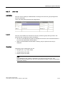
The following conventions are used in the text and will help you to read the manual more
effectively:
Notation
Scope
"Add screen"
•
•
•
Terminology that occurs in the user interface, e.g., dialog
names, tabs, buttons, menu commands.
Inputs required, e.g., limit values, tag values
Path information
"File > Edit"
Operational sequences, e.g., menu commands/shortcut menu
commands.
<F1>, <Alt + P>
Keyboard inputs
Please observe notes labeled as follows:
Note
Notes containing important information about the product and its use or a specific section of
the documentation to which you should pay particular attention.
WinCC flexible 2005 Runtime
User's Manual, Edition 06/2005, 6AV6691-1BA01-0AB0
iii
Preface
Trademarks
HMI®
SIMATIC®
SIMATIC HMI®
SIMATIC ProTool®
SIMATIC WinCC®
SIMATIC WinCC flexible®
Third parties using for their own purposes any other names in this documentation which refer
to trademarks might infringe upon the rights of the trademark owners.
Further Support
If you have any technical questions, please get in touch with your Siemens representative or
agent responsible.
You will find your contact person at:
"http://www.siemens.com/automation/partner"
You will find a guide to the technical documentation offered for the individual SIMATIC
Products and Systems here at:
"http://www.siemens.com/simatic-tech-doku-portal"
The online catalog and order system is found under:
"http://mall.automation.siemens.com/"
Training Centers
Siemens offers a number of training courses to familiarize you with the SIMATIC S7
automation system. Please contact your regional training center or our central training center
in D 90327 Nuremberg, Germany for details:
Telephone: +49 (911) 895-3200.
Internet: "http://www.sitrain.com"
iv
WinCC flexible 2005 Runtime
User's Manual, Edition 06/2005, 6AV6691-1BA01-0AB0
Preface
Technical Support
You can reach the Technical Support for all A&D products
via the Web formula for the Support Request
"http://www.siemens.com/automation/support-request"
Phone:
+ 49 180 5050 222
Fax:
+ 49 180 5050 223
Additional information about our Technical Support can be found on the Internet pages
"http://www.siemens.com/automation/service"
Service & Support on the Internet
In addition to our documentation, we offer our Know-how online on the internet at:
"http://www.siemens.com/automation/service&support"
where you will find the following:
•
The newsletter, which constantly provides you with up-to-date information on your products.
•
The right documents via our Search function in Service & Support.
•
A forum, where users and experts from all over the world exchange their experiences.
•
Your local representative for Automation & Drives.
•
Information on field service, repairs, spare parts and more under "Services".
WinCC flexible 2005 Runtime
User's Manual, Edition 06/2005, 6AV6691-1BA01-0AB0
v
Preface
vi
WinCC flexible 2005 Runtime
User's Manual, Edition 06/2005, 6AV6691-1BA01-0AB0
Table of contents
Preface ........................................................................................................................................................i
1
Introduction to WinCC flexible Runtime .................................................................................................. 1-1
2
Functional scope..................................................................................................................................... 2-1
3
System prerequisites .............................................................................................................................. 3-1
4
Setting up WinCC flexible Runtime ......................................................................................................... 4-1
5
4.1
Installing WinCC flexible Runtime.............................................................................................. 4-1
4.2
Electrical installation .................................................................................................................. 4-2
4.3
Connection to the controller ....................................................................................................... 4-3
4.4
Settings of the Runtime software ............................................................................................... 4-4
4.5
Test project ................................................................................................................................ 4-5
4.6
Transferring a project................................................................................................................. 4-6
4.7
Runt the project.......................................................................................................................... 4-8
4.8
Backup configuration data ......................................................................................................... 4-9
4.9
Stop runtime............................................................................................................................... 4-9
Runtime functionality .............................................................................................................................. 5-1
5.1
Screen objects in Runtime ......................................................................................................... 5-1
5.2
Alarms in Runtime...................................................................................................................... 5-2
5.3
Tags in Runtime ......................................................................................................................... 5-4
5.4
Log files in Runtime ................................................................................................................... 5-4
5.5
5.5.1
5.5.2
5.5.3
5.5.4
5.5.4.1
5.5.4.2
5.5.4.3
5.5.4.4
5.5.4.5
5.5.5
5.5.5.1
5.5.5.2
5.5.6
5.5.6.1
5.5.6.2
5.5.6.3
5.5.6.4
Recipes in Runtime.................................................................................................................... 5-6
Recipes in Runtime.................................................................................................................... 5-6
Structure of recipes.................................................................................................................... 5-7
Structure of recipe data records................................................................................................. 5-8
Recipe application...................................................................................................................... 5-9
Transfer of recipe data records.................................................................................................. 5-9
Configuration of recipes ........................................................................................................... 5-10
Scenario: Entering recipe data records in Runtime ................................................................. 5-12
Scenario: Manual production sequence .................................................................................. 5-13
Scenario: Automatic production sequence .............................................................................. 5-15
Displaying recipes.................................................................................................................... 5-16
Viewing and editing recipes in Runtime................................................................................... 5-16
Behavior of the recipe view in Runtime ................................................................................... 5-18
Recipe data record administration ........................................................................................... 5-18
Recipe data record administration ........................................................................................... 5-18
Synchronizing a recipe data record ......................................................................................... 5-20
Read recipe data record from PLC .......................................................................................... 5-21
Transfer recipe record to PLC.................................................................................................. 5-21
WinCC flexible 2005 Runtime
User's Manual, Edition 06/2005, 6AV6691-1BA01-0AB0
vii
Table of contents
6
7
viii
5.5.6.5
5.5.6.6
5.5.7
5.5.7.1
5.5.7.2
Exporting and importing recipe data records ........................................................................... 5-22
Reactions to modifications of the recipe structure ................................................................... 5-23
Example ................................................................................................................................... 5-24
Example: Creating a recipe...................................................................................................... 5-24
Example: Configuring a recipe screen ..................................................................................... 5-26
5.6
Reports in Runtime .................................................................................................................. 5-27
5.7
System functions and scripts in Runtime ................................................................................. 5-28
5.8
Security in Runtime .................................................................................................................. 5-29
5.9
Further operating options in Runtime....................................................................................... 5-31
Operating a project in Runtime ............................................................................................................... 6-1
6.1
6.1.1
6.1.2
6.1.3
6.1.3.1
6.1.3.2
6.1.3.3
6.1.3.4
6.1.3.5
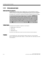
Basics for operation in Runtime ................................................................................................. 6-1
Introduction ................................................................................................................................ 6-1
Operation with mouse and keyboard ......................................................................................... 6-2
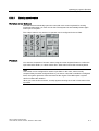
Operating the touch screen device ............................................................................................ 6-4
Operating touch objects ............................................................................................................. 6-4
Input of values............................................................................................................................ 6-5
Entering alphanumeric values.................................................................................................... 6-6
Entering numeric values............................................................................................................. 6-7
Calling the infotext...................................................................................................................... 6-8
6.2
6.2.1
6.2.2
6.2.3
6.2.4
6.2.5
6.2.6
6.2.7
6.2.8
6.2.9
6.2.10
6.2.11
6.2.12
6.2.13
6.2.14
6.2.15
6.2.16
6.2.17
6.2.18
6.2.19
6.2.20
6.2.21
6.2.22
Operating graphic objects .......................................................................................................... 6-9
Button ......................................................................................................................................... 6-9
Switch....................................................................................................................................... 6-10
IO field ...................................................................................................................................... 6-12
Graphic I/O field ....................................................................................................................... 6-14
Symbolic IO field ...................................................................................................................... 6-15
Alarm indicator ......................................................................................................................... 6-16
Alarm view................................................................................................................................ 6-17
Simple alarm view .................................................................................................................... 6-19
Recipe view.............................................................................................................................. 6-21
Simple recipe view ................................................................................................................... 6-24
Bar............................................................................................................................................ 6-26
Trend view................................................................................................................................ 6-27
Slider control ............................................................................................................................ 6-29
Gauge....................................................................................................................................... 6-30
Date/time field .......................................................................................................................... 6-31
Clock ........................................................................................................................................ 6-32
User view ................................................................................................................................. 6-33
Simple user view ...................................................................................................................... 6-35
Symbol library .......................................................................................................................... 6-37
Status force .............................................................................................................................. 6-38
HTML browser.......................................................................................................................... 6-40
Sm@rtClient view..................................................................................................................... 6-42
HMI system alarms ................................................................................................................................. 7-1
WinCC flexible 2005 Runtime
User's Manual, Edition 06/2005, 6AV6691-1BA01-0AB0
Introduction to WinCC flexible Runtime
1
Introduction
WinCC flexible Runtime is a high-performance and comprehensive software for the
visualization of processes in projects you created with the WinCC flexible Advanced
programming software.
Modern automation concepts are extremely demanding on process visualization. Process
control close to machines must in particular meet the demands for simple, high-performance
control of the processes. The goal is to present process data to the operator quickly and
clearly in a form that can be easily understood, such as a trend display. This increasingly
requires process displays that simplify understanding of the actual process. It is also
becoming more important to be able to archive the data, e.g. for quality control. This makes it
necessary to log process data at machine level.
WinCC flexible Runtime is designed for visualization and operation of machines and small
systems. The Runtime software has a window-based pixel-graphics user interface. Due to its
short response times, the software features secure process operation, jogging at the
machine and secure data acquisition.
Licensing
If you install the WinCC flexible Runtime software on a standard PC or a panel PC, you will
require a license for unrestricted use. WinCC flexible Runtime runs in a non-licensed mode if
the licensing is missing.
• PC: The license is supplied with WinCC flexible Runtime.
• Panel PCs: The license and WinCC flexible Runtime are supplied with the device.
Components of WinCC flexible
The configuration software WinCC flexible Advanced is used to create your project data on a
PC or PG that is operating on a Windows platform.
The process visualization software WinCC flexible Runtime is used to run the user program
under Windows and to visualize the process. WinCC flexible Runtime is also used on the
configuration computer to test and simulate the compiled project file.
There are also a number of options with enhanced functions available for WinCC flexible
Runtime. These can be ordered separately as required.
WinCC flexible 2005 Runtime
User's Manual, Edition 06/2005, 6AV6691-1BA01-0AB0
1-1
Introduction to WinCC flexible Runtime
1-2
WinCC flexible 2005 Runtime
User's Manual, Edition 06/2005, 6AV6691-1BA01-0AB0
Functional scope
2
Dependencies of the functions
The functional scope of WinCC flexible Runtime depends on the following conditions:
• Hardware of the HMI device
The functionality is determined by the features of the HMI device used, such as memory
capacity and the number of function keys.
• Licensing / licensing model
The scope of functions and performance is determined by the licensing and the licensing
model, for example, with respect to the number of tags (power tags.)
• Runtime options
You can access additional functions by installing the options (e.g. remote access using
the Sm@rtClient display.)
Functional scope
Functionality of WinCC flexible Runtime:
• Convenient process visualization on a Windows-type user interface
• Large selection of standard I/O fields, bars, trend displays, vector graphics and buttons
• Integrated alarm system
• Dynamic positioning of objects
• Archiving of alarms and process values
• Recipes
• Visual Basic Script for user functions
• Standard couplings to SIMATIC S7, SIMATIC S5 and SIMATIC 505 as well as to PLCs
from other manufacturers
• HTML browser
• Input protection by means of user groups, passwords and log off times
• Remote access using the Sm@rtClient view
WinCC flexible 2005 Runtime
User's Manual, Edition 06/2005, 6AV6691-1BA01-0AB0
2-1
Functional scope
2-2
WinCC flexible 2005 Runtime
User's Manual, Edition 06/2005, 6AV6691-1BA01-0AB0
System prerequisites
3
System requirements for PCs
If you wish to run WinCC flexible Runtime on a PC, it must satisfy the following system
requirements:
• Operating system: Windows 2000 SP4 or Windows XP Professional SP1/SP2
• Processor: minimum Pentium II, 233 MHz; recommended Pentium III, 500 MHz
• Graphic controller: minimum VGA; recommended SVGA with hardware acceleration
• Resolution: minimum 640 x 480 pixels; recommended 1024 x 768 to 1600 x 1200 pixels
• RAM: minimum 64 MB; recommended are 128 MB or more
• Free hard disk space: at least 100 MB (without considering log files)
In addition to the space needed by WinCC flexible Runtime, Windows also requires
space on the hard disk, e.g. for the swap file. For further information, refer to your
Windows documentation.
• CD-ROM drive
• For WinCC flexible Runtime licensing you must have access to a 3.5"/1.44 MB FD drive
(direct or via Ethernet connection).
Note
For multilingual configurations, use the MUI (multilingual user interface) version of the
operating system.
WinCC flexible 2005 Runtime
User's Manual, Edition 06/2005, 6AV6691-1BA01-0AB0
3-1
System prerequisites
3-2
WinCC flexible 2005 Runtime
User's Manual, Edition 06/2005, 6AV6691-1BA01-0AB0
Setting up WinCC flexible Runtime
4.1
4.1
4
Installing WinCC flexible Runtime
Supported devices
WinCC flexible Runtime will run on the following Windows-based systems:
• Standard PC
• SIMATIC Panel PCs: PC 670, PC 677, PC 870, PC 877, PC IL 70, PC IL 77
• SINUMERIK Panel PCs: OP 010, OP 012, OP 015, OP 015A, TP 012, TP 015A
• SIMOTION Panel PCs: P012K, P012T, P015K, P012T, PC-R Key, PC-R Touch
Installation on the PC
Install System WinCC flexible Runtime on your system, if you have not done that yet.
Install WinCC flexible Runtime from the "WinCC flexible Runtime" CD. A license (license
key) is required to run the Runtime software.
Notice
WinCC flexible Runtime runs in demo mode only if you do not have a license. In demo
mode, you are prompted to acknowledge specific messages at regular intervals.
1. Install the runtime software from the CD.
If the autorun function is enabled for your CD-ROM drive, the CD browser is run
automatically when the CD is inserted. Otherwise, run Setup by selecting
"WinCCflexible\Runtime\setup.exe" from the CD.
2. Select the user interface language of the Setup program under "Language."
3. Select "Installation", then run the "WinCC flexible Runtime" setup.
4. Follow the setup instructions on the screen.
5. Install the license when you are prompted to do so.
Note
If, when installing the Runtime software, you do not have a license, you can install this
later using the Automation License Manager. The Automation License Manager is
automatically installed during the WinCC flexible installation.
WinCC flexible 2005 Runtime
User's Manual, Edition 06/2005, 6AV6691-1BA01-0AB0
4-1
Setting up WinCC flexible Runtime
4.2 Electrical installation
4.2
4.2
Electrical installation
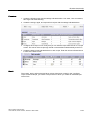
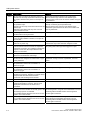
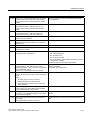
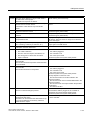
Connecting the PC to the controller
The PC is connected to the controller via a communciation processor or via the COM1 to
COM4 ports. Please refer to the hardware description from the manufacturer for the proper
electrical installation of your PC.
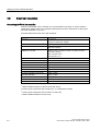
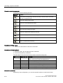
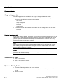
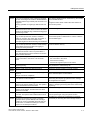
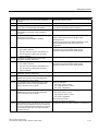
The table below shows the use of the interfaces:
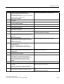
Controller
PC interface
SIMATIC S5 over AS511
COM1 / COM2
requires an RS232/TTY adapter
SIMATIC S5 via PROFIBUS DP
1)
via CP CP 5511, CP 5512, CP 5611
SIMATIC S7 via PPI
via CP CP 5511, CP 5512, CP 5611, CP 5613, CP 5614
via PC/PPI adapter 2)
SIMATIC S7 via MPI
via CP CP 5511, CP 5512, CP 5611, CP 5613, CP 5614
via PC/MPI adapter 3)
via PC adapter USB 3)
via Teleservice V5.1
4-2
SIMATIC S7 via PROFIBUS DP 4)
via CP CP 5511, CP 5512, CP 5611, CP 5613, CP 5614
SIMATIC S7 via Ethernet (TCP/IP)
via CP CP 1512, CP 1612, CP 1613
SIMATIC 505
COM1 / COM2, RS232 interface
SIMATIC 505 via PROFIBUS DP
via CP CP 5511, CP 5512, CP 5611
OPC
Ethernet network cards
Allen Bradley via DF, DH+, DH485
COM1 / COM2
LG (Lucky Goldstar) GLOFA GM
COM1 / COM2
Mitsubishi MELSEC
COM1 / COM2
Modicon MODBUS
COM1 / COM2
GE Fanuc
COM1 / COM2
Omron Hostlink/Multilink
COM1 / COM2
1)
WinCC flexible Runtime is passive node (DP slave)
2)
Point-to-point connection with S7-200 only, no configuration transfer
3)
Point-to-point connection with S7-300 or S7-400 only
4)
WinCC flexible Runtime is active node
WinCC flexible 2005 Runtime
User's Manual, Edition 06/2005, 6AV6691-1BA01-0AB0
Setting up WinCC flexible Runtime
4.3 Connection to the controller
4.3
4.3
Connection to the controller
Connection to the controller
Connect you HMI device to the controller in order to allow you to simulate your project online
with the controller. You can also test the project by calling the simulator. In this case, you do
not need an online connection to the controller.
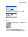
Setting the PG / PC interface
PROFIBUS DP communication
1. Select "Start > Settings > Control Panel", then select "Set PG/PC interface."
Select PROFIBUS under used module parameters.
2. Click "Properties". The DP profile is selected in the network parameters.
3. Select universal (DP/FMS), then confirm with OK.
4. Click "Properties" again.
5. Select the DP profile again, then confirm with OK.
MPI communication
1. Select "Start > Settings > Control Panel", then select "Set PG/PC interface."
2. Click "Properties", then set the parameters on the MPI network tab for the HMI device so
that this is the only master on the bus.
Only one of several HMI devices may be operated as master on the MPI bus. Verify the
network settings of the connected devices.
Note
For comprehensive information relating to communication between the controller and the
HMI device, refer to the communication user manual.
WinCC flexible 2005 Runtime
User's Manual, Edition 06/2005, 6AV6691-1BA01-0AB0
4-3
Setting up WinCC flexible Runtime
4.4 Settings of the Runtime software
4.4
4.4
Settings of the Runtime software
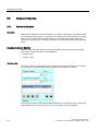
Principle
In the configuration software WinCC flexible, make the following settings for the Runtime
software:
• Display on the PLC
In WinCC flexible, you configure the Runtime layout of the generated project: Select
whether to start the project in full-screen mode, or in a window smaller than the screen
size. In full-screen mode, the project is zoomed to the full screen. There will be no
window and operator control elements for this view.
Note
If the HMI screen does not match the configured size (in pixels), the project appears only
on a part of the screen when opened in full-screen mode.
To start the system in full-screen mode, open the "Device settings" dialog box in the
project view in WinCC flexible. Under "Runtime Settings", set the "Full-screen mode"
check box. You can hide the taskbar under WIndows as required. To hide the taskbar,
select "Start > Settings > Taskbar", then reset the "Always on Top" and "Auto hide" check
boxes on the "Taskbar properties" dialog box.
• Disabling program switching
In order to prevent the operator from calling other applications in Runtime, you may lock
program switching. To do so, open the "Device settings" dialog box in the project view,
then set the "Disable program switching" and "Full-screen mode" check boxes. Also hide
the taskbar under Windows as described earlier.
Note
If you decide to lock program switching, you should always configure a function key or
button for calling the "StopRuntime" system function. Otherwise, it will not be possible to
exit WinCC flexible Runtime or Windows.
When program switching is disabled, the <Ctrl+Alt+Del> keystroke function is also
disabled. Under Windows 2000, this will make it impossible, for example, to log in to your
device after the screensaver has started. In Windows 2000, you can disable the
<Ctrl+Alt+Del> log-in key combination. Open the "Control Panel > Users > Passwords",
then reset the "Press Ctrl + Alt + Del before logging on" check box on the "Advanced"
tab.
• Screen saver
A screensaver is no longer required for most modern screens and can even damage
them. These monitors switch to hibernate mode as soon as the video signal has not
changed for a specified time. A conventional screensaver would prevent this and thus
reduce the service life of your monitor.
4-4
WinCC flexible 2005 Runtime
User's Manual, Edition 06/2005, 6AV6691-1BA01-0AB0
Setting up WinCC flexible Runtime
4.5 Test project
Note
In case you do want to use a screensaver, please note that WinCC flexible Runtime is
only released for operation with the standard Windows screensavers.
• Setting the time zone
Make sure that the correct time zone is set on the PC on which the runtime software is
installed. To set the time zone in Windows, select Start > Settings > Control Panel >
Date/Time.
4.5
4.5
Test project
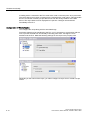
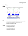
Function
WinCC flexible is supplied with a simulator software which you can use to test your project
offline. The simulator is a separate application. It allows you to debug the functions of
configured graphics, graphic objects, alarms etc.
The simulator simulates the control as follows:
• Defined modification of the values of configured tags, e.g. in increments or decrements,
sine-wave, random or by bit-shifting.
The simulation/runtime components must also be installed on your programming device in
order to run a simulation.
Principle
You have various options of simulating your project:
• Simulation with controller connection
You can simulate you project directly in Runtime. In this case, tags and range pointers
will only function if your programming device is interconnected with a corresponding
controller.
By connecting your PC / PG to the controller, you can achieve an authentic simulation of
your configured HMI device in Runtime. For simulation with WinCC flexible, select
"Compiler" > "Start Runtime" from the "Project" menu. Alternatively, click on the
symbol in the "Compiler" toolbar.
• Simulation without controller connection
The simulation program installed with WinCC flexible Runtime allows offline simulation of
your project, including its tags and flags. Specify the parameters of flags and tags in a
simulation table that will be read by the simulation program of WinCC flexible Runtime.
For simulation with the simulator, select "Compiler > Start Runtime with simulator" from
the "Project" menu. Alternatively, click on the
WinCC flexible 2005 Runtime
User's Manual, Edition 06/2005, 6AV6691-1BA01-0AB0
symbol in the "Compiler" toolbar.
4-5
Setting up WinCC flexible Runtime
4.6 Transferring a project
• Simulation in integrated mode
An integrated configuration in STEP 7 allows you to simulate a controller connection with
PLCSIM. For more information, please see the STEP 7 documentation.
Handling instructions
The following steps show the basic procedures for simulating a project offline without
controller connection.
1. Start by creating a project as it is going to be run later with an interconnected controller.
2. Save and compile the project.
3. Launch the simulator directly from the running configuration software. Select "Compiler" >
start Runtime with simulator" from the "Project" menu. Alternatively, click on the
symbol in the "Compiler" toolbar.
When you simulate the project for the first time, the simulator is started with a new, empty
simulation table. If you have already created a simulation table for your project, it will be
opened.
The simulation table "*.sim" contains all your settings for the simulation of tags and flags.
4. You now manipulate the tags and flags of your project in the simulation table.
You can monitor the profile of the changing value by switching the task from simulation to
the project.
5. You can save all settings made in this table for project simulation to a file. To do so,
select "File > Save" in the Simulator, then type in a file name ("*.sim".)
You can now always retrieve these settings in order to simulate your project again. The
condition is here, that you have not reconfigured any of the tags or flags you want to
simulate in your project in the meantime.
4.6
4.6
Transferring a project
Overview
Various scenarios are possible for transferring the project:
• WinCC flexible Runtime is installed on the same PC as the WinCC flexible programming
software.
• WinCC flexible Runtime and the WinCC flexible programming software are installed on
different systems. In this case, the project must be downloaded from the programming
device to the destination device.
In the first step, you need to set the corresponding transfer properties in the "Loader
menu" on the HMI device.
4-6
WinCC flexible 2005 Runtime
User's Manual, Edition 06/2005, 6AV6691-1BA01-0AB0
Setting up WinCC flexible Runtime
4.6 Transferring a project
Note
Depending on the configuration, the transfer safety prompt asks if you really want to
overwrite the existing recipe data and password lists with the data from the configuration.
The programming software and runtime software are on the same system
If the configuration software and WinCC flexible Runtime are on the same system, proceed
as follows:
1. Create the project and name it, for example, Myproject.hmi. Compile the project data in
the next step.
The compiled file with the file name extension *.fwx will be stored in the folder containing
the project file, e.g. "Myproject.fwx."
2. Start WinCC flexible Runtime directly from the running configuration software. Select
"Compiler" > start Runtime" from the "Project" menu. Alternatively, click on the
symbol
in the "Compiler" toolbar.
3. You may test and operate the project online with the controller if you have configured the
corresponding communication.
Configuration software and Runtime software on different systems
If the programming software and WinCC flexible Runtime are installed on two different
systems, proceed as follows:
1. Create the project and name it, for example, Myproject.hmi. Compile the project data in
the next step.
The compiled file with the file name extension *.fwx, e.g. Myproject.fwx, is stored in the
same folder.
2. To transfer the compiled file via cable:
Depending on the required type of transfer, use a suitable standard cable to interconnect
the HMI device with the programming device, then switch on the HMI device.
Note
If the HMI device is a PC, you can transfer the compiled file without using the loader, for
example, via Ethernet. To do so, double-click the compiled file on your PC to start
Runtime.
3. Download the compiled file from the programming device to your PLC.
Windows provides the following options of transferring the compiled file:
– Copy the file *.fwx to the PLC via the parallel or serial interface, either via dial-up
connection under Windows 2000 or the network.
– Copy the *.fwx file to a diskette and then from the diskette to the destination PC.
WinCC flexible 2005 Runtime
User's Manual, Edition 06/2005, 6AV6691-1BA01-0AB0
4-7
Setting up WinCC flexible Runtime
4.7 Runt the project
4.7
4.7
Runt the project
Introduction
You can start the project immediately after its transfer.
Project start modes
Options of starting a WinCC flexible project on a Runtime PC:
• Running it from the Explorer
You can run the project by double-clicking its file name in Windows Explorer.
• Starting together with Runtime
Enter the project file in "HmiRT.ini" in order to run it with the start of WinCC flexible
Runtime by means of the Windows Start menu.
• Run from the command line
To run your project, type in the following command either at the MS-DOS prompt, or on
the "Start > Run" command line in Windows, and then press <Enter>.
c:\Programs\Siemens\SIMATIC WinCC flexible\WinCC flexible 2005
Runtime\HmiRTm.exe c:\project\myproject.fwx
• Autostart
– If your project is linked to the Autostart directory of the Windows start menu, it will be
automatically upon system startup.
– It is also possible to define the autostart settings in the "Settings" dialog box of the
WinCC flexible Runtime loader.
Note
You can start the loader with the Windows Start menu command
"SIMATIC\WinCC flexible 2005 Runtime\WinCC flexible 2005 Runtime Loader".
4-8
WinCC flexible 2005 Runtime
User's Manual, Edition 06/2005, 6AV6691-1BA01-0AB0
Setting up WinCC flexible Runtime
4.8 Backup configuration data
4.8
4.8
Backup configuration data
Principle
Several years of operation in a rugged industrial environment may damage the hard disk
drive of your HMI device. To ensure that you can retrieve all programs and settings to the
new hard disk, create a backup copy of your hard disk configuration data. Refer to the
operating instructions of the HMI device for a detailed description of creating a backup.
Procedure
1. Run the backup program as directed in the description included with the SIMATIC HMI
device.
You have thus prepared the conditions for putting your HMI device into operation again
without any significant loss of time after you replace the hard disk drive.
A commonly available software can also be used to generate a backup copy.
4.9
4.9
Stop runtime
Introduction
You define the steps in closing Runtime in the user program:
Procedure
1. When Runtime is running in window mode, you can close it simply by clicking "Close."
2. When Runtime is running in full-screen mode, you can close it by means of the program
switching function and the Task Manager.
3. When Runtime is running in full-screen mode and program switching is disabled for the
project, the closing sequence of Runtime must be configured separately. Actuate the
relevant button to close Runtime.
WinCC flexible 2005 Runtime
User's Manual, Edition 06/2005, 6AV6691-1BA01-0AB0
4-9
Setting up WinCC flexible Runtime
4.9 Stop runtime
4-10
WinCC flexible 2005 Runtime
User's Manual, Edition 06/2005, 6AV6691-1BA01-0AB0
Runtime functionality
5.1
5.1
5
Screen objects in Runtime
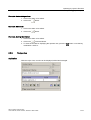
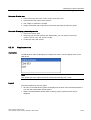
Overview
WinCC flexible Runtime offers the following objects for operating and monitoring:
• Button
• Switch
• I/O field
• Graphic I/O field
• Symbolic IO field
• Alarm indicator
• Alarm view
• Alarm window
• Recipes view
• Bar
• Trend view
• Slider control
• Gauge
• Date/time field
• Clock
• User view
• Symbol library
• Status force
• HTML browser
• Sm@rtClient view
WinCC flexible 2005 Runtime
User's Manual, Edition 06/2005, 6AV6691-1BA01-0AB0
5-1
Runtime functionality
5.2 Alarms in Runtime
5.2
5.2
Alarms in Runtime
Alarms
Alarms indicate events and states on the HMI device which have occurred in the system, in
the process or on the HMI device itself. A status is reported when it is received.
An alarm could trigger one of the following alarm events:
• Activate
• Deactivate
• Acknowledge
The configuration engineer defines which alarms must be acknowledged by the user.
An alarm may contain the following information:
• Date
• Time
• Alarm text
• Location of fault
• Status
• Alarm class
• Alarm number
• Acknowledgement group
Alarm classes
Alarms are assigned to various alarm classes.
• Operation
Warning alarms usually indicate states of a plant such as "Motor switched on". Alarms in
this class do not require acknowledgement.
• Error
Alarms in this class must always be acknowledged. Alarms normally indicate critical
errors within the plant such as "Motor temperature too high".
• System
System alarms indicate states or events which occur on the HMI device.
System alarms provide information on occurrences such as operator errors or
communication faults.
• STEP 7 alarm classes
The alarm classes configured in STEP 7 are also available to the HMI device.
• Custom alarm classes
The properties of this alarm class must be defined in the configuration.
5-2
WinCC flexible 2005 Runtime
User's Manual, Edition 06/2005, 6AV6691-1BA01-0AB0
Runtime functionality
5.2 Alarms in Runtime
Alarm buffer
Alarm events are saved to an internal, volatile buffer. The size of this alarm buffer depends
on the HMI device type.
Alarm log
When alarm logging is enabled, alarm events are output directly to the printer.
You can set the logging function separately for each alarm. The system outputs "activated"
and "deactivated" alarm events to the printer.
The output of alarms of the "System" class to a printer must be initiated by means of the
corresponding alarm buffer. This outputs the content of the alarm buffer to the printer. To be
able to initiate this print function, you need to configure a corresponding control object in the
project.
Alarm log
Alarm events are stored in an alarm log, provided this log file is configured. The capacity of
the log file is limited by the storage medium and system limits.
Alarm view
The alarm view shows selected alarms or events from the alarm buffer or alarm log. Whether
alarm events have to be acknowledged or not is specified in your configuration.
Alarm window
If configured, an alarm window shows all pending alarms or alarms awaiting
acknowledgement of a particular alarm class. The alarm window is displayed as soon as a
new alarm occurs.
You can configure the order in which the alarms are displayed. You can choose to display
the alarms in ascending or descending order of their occurrence. The alarm window can also
be set to indicate the exact location of the fault, including the date and time of the alarm
event.
Alarm indicator
The alarm indicator is a graphic symbol that is displayed on the screen when an alarm of the
specified alarm class is activated.
The alarm indicator can have one of two states:
• Flashing: At least one unacknowledged alarm is pending.
• Static: The alarms are acknowledged but at least one of them is not yet deactivated. The
number indicates the number of queued alarms.
WinCC flexible 2005 Runtime
User's Manual, Edition 06/2005, 6AV6691-1BA01-0AB0
5-3
Runtime functionality
5.3 Tags in Runtime
5.3
5.3
Tags in Runtime
Definition
Tags correspond to defined memory areas on the HMI device, to which values are written
and/or from which values are read. This action can be initiated by the PLC, or by the
operator at the HMI device.
5.4
5.4
Log files in Runtime
Overview
Alarm events and process values can be saved to log files.
Examples of alarm events are the incoming, acknowledged and outgoing events occurring
with an alarm message.
Process value logging is used for the following purposes, for example:
• Early detection of danger / fault states
• Increase of productivity
• Enhancement of product quality
• Optimization of maintenance cycles
• Documentation of processes
• Quality assurance
Memory options
Depending on the configuration, the logs are written to a file or stored in a database set up
for this purpose.
• Logging to a CSV file
The project engineer must have specified a folder path for storing the CSV file containing
your logged data. This references the storage location.
CSV format table columns are separated by separators, the table rows are terminated by
a line break character. This allows you to evaluate or edit your log data using an external
text editor or spreadsheet program, for example.
• Logging to a database
By storing your log files in a database, you can utilize the full database functionality for
further processing and analysis of the logged data.
Databases tested and released for WinCC flexible:
– MS Data Engine 97 and MS Data Engine 2000
– MS Access 97 and MS Access 2000
– MS SQL Server 7.0 and MS SQL Server 2000
5-4
WinCC flexible 2005 Runtime
User's Manual, Edition 06/2005, 6AV6691-1BA01-0AB0
Runtime functionality
5.4 Log files in Runtime
Logging methods used in WinCC flexible Runtime:
• Circular log
• Segmented circular log
• Log with level-dependent system alarm
• Log file with data volume-based system alarm
Alarm logs
Alarms in the project indicate fault states and operating states of a process. They are
generally triggered by the controller. Alarms can be output to the HMI in the form of images.
WinCC flexible lets you log alarms and document operational states and error states of the
plant.
The following data are logged to the file:
• Date and time of alarm
• Alarm number
• Alarm tags (up to 8)
• Alarm status
• Alarm text (optional)
• Fault location (optional)
All alarms are assigned to a specific alarm class. All alarm classes can be logged.
Alarms can be logged either automatically, or by operator intervention.
The contents of log files can be output to the HMI, if a corresponding alarm view has been
configured.
Data logs
In Runtime, the process values are logged, processed and, depending on the project, written
either to files or to the log database.
Data logging is controlled by means of cyclic operations and events. Logging cycles are
used to ensure continuous acquisition and storage of the data. In addition, data logging can
also be triggered by events, e.g. when a value changes.
WinCC flexible 2005 Runtime
User's Manual, Edition 06/2005, 6AV6691-1BA01-0AB0
5-5
Runtime functionality
5.5 Recipes in Runtime
5.5
5.5.1
5.5
Recipes in Runtime
Recipes in Runtime
Overview
Recipes are a collection of associated data, e.g. machine configuration or production data.
You can transfer these data, for example, from the HMI device to the controller in a single
step in order to change the production variant. If you have programmed directly at the
machine, for example, you can transfer the data to your HMI device and write these to the
recipe.
Operating recipes in Runtime
WinCC flexible offers two options of viewing and editing recipes and the corresponding
recipe data records in Runtime on the HMI device:
• Recipes view
• Recipe screen
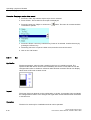
Recipes view
The recipe view is a screen object that is configured in the "Screens" editor. For example,
you can specify what operating function the recipe view will have in Runtime:
The recipe view shows recipe data records in tabular form. The Recipe view is particularly
useful if data records are small in size or only a few values are to be modified.
5-6
WinCC flexible 2005 Runtime
User's Manual, Edition 06/2005, 6AV6691-1BA01-0AB0
Runtime functionality
5.5 Recipes in Runtime
Recipe screen
A recipe screen represents a process screen which you configured as individual input screen
form by means of an individual layout of I/O fields and other screen objects in the "Screens"
editor. This makes it possible for you to input parameter data in the context of machine
visualization. The I/O fields for a recipe can be distributed over multiple recipe screens, with
topical organization of recipe elements, for example. The operating functions for the recipe
screens must be configured explicitly in the process screens.
5.5.2
Structure of recipes
Introduction
A product often has several variants. For example, product variants can differ with respect to
size or quality. This condition is accurately reflected in a recipe.
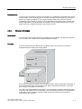
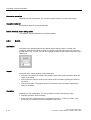
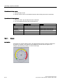
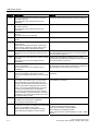
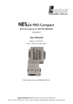
Principle
A recipe consists of recipe data records containing values. The structure of a recipe is
explained using the example of a filing cabinet.
Each recipe represents a drawer of the file cabinet shown, and thus precisely one product. If
the fruit juice mixing plant is producing orange, apple, and tropical fruit flavors, you would
then configure one recipe for each flavor.
You define the recipe elements in the recipe. A recipe element consists of the display name
and a tag. The display names are indicated in the recipe data records and on the HMI device
in the recipe view. In Runtime, the appropriate tag value is read from the controller or
transferred to the controller.
WinCC flexible 2005 Runtime
User's Manual, Edition 06/2005, 6AV6691-1BA01-0AB0
5-7
Runtime functionality
5.5 Recipes in Runtime
5.5.3
Structure of recipe data records
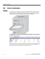
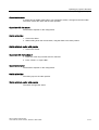
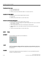
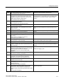
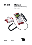
Introduction
A recipe data record corresponds to a file card in an individual drawer and thus to a single
product variant. If the fruit juice mixing plant is producing juice, nectar, and fruit drinks, you
would then create a recipe data record in the recipe for each product variant. In this case,
the product variants consist of the different mixing ratios for the ingredients.
A recipe data record is a set of values for the tags defined in the recipe. You enter the values
in the input fields. You can enter the values either during configuration or during runtime on
the HMI device or the machine.
To produce a product, you transfer the appropriate recipe data record from the HMI device to
the connected controller. The values in the recipe data record cannot be changed on the
HMI device unless the configuring engineer has provided for this.
5-8
WinCC flexible 2005 Runtime
User's Manual, Edition 06/2005, 6AV6691-1BA01-0AB0
Runtime functionality
5.5 Recipes in Runtime
Editing recipe data records
You can edit recipe data records during configuration or in runtime on the HMI device.
• During configuration, you can define recipes in the "Recipes" editor in the "Elements" tab.
You can enter values in the recipe data records in the "Data records" tab.
• During runtime, you have the option of entering recipe data record values directly on the
HMI device or importing them via a CSV file. You can also export the recipe data records
to a CSV file.
5.5.4
Recipe application
5.5.4.1
Transfer of recipe data records
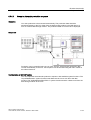
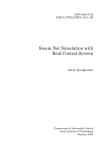
Introduction
Recipe data records can be transferred in Runtime between external data storage media,
e.g. a flash memory, an HMI device and a controller.
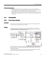
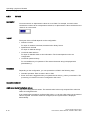
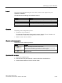
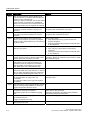
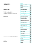
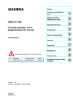
Principle
The figure below shows how recipe data records can be transferred. You configure the
appropriate functionality for transferring data records in the recipe view. In a recipe screen,
you use the system functions provided for this purpose.
The HMI device stores recipe data records on a storage medium such as a flash memory
device or hard disk. You can edit a recipe data record in a recipe view or recipe screen on
the HMI device display.
(1) Save: Values you change on the recipe view or recipe screen are written to the recipe
data record on the storage medium by executing the "Save" function.
WinCC flexible 2005 Runtime
User's Manual, Edition 06/2005, 6AV6691-1BA01-0AB0
5-9
Runtime functionality
5.5 Recipes in Runtime
(2) Load: The "Load" function is used to update the values of recipe tags shown on the
recipe screen with the values of the recipe data record of the storage medium. The function
overwrites any values changed on the recipe screen. The "Load" function is executed for the
Recipe view when the data record is selected again.
(3) Write to controller: The values deltas of the recipe view and recipe screen are
downloaded to the PLC by calling the "Write to controller" function.
(4) Read from controller: Call the "Read from controller" function to update the indicated
values of the recipe view and recipe screen with the controller values. The function
overwrites any data changed on the recipe view or screen.
(5) Synchronization with control: In your configuration, you can decide to synchronize the
values in the recipe view with the values of the recipe tags by setting the "Synchronization
with control" function. After this synchronization, both the recipe tags and the recipe view
contain the current updated values. When the "Variables offline" setting is disabled for the
recipe, the current values are also applied in the controller.
(6) Import, Export: A data record can be exported to an external data carrier in order to
process it in MS Excel, for example. The data record is there stored in *.csv format.
5.5.4.2
Configuration of recipes
Introduction
You configure recipes according to your intended application. To write a value to a recipe
data record on your HMI device without disturbing the current process, you need
configuration settings other than those required for assigning parameters to a machine.
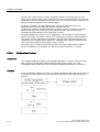
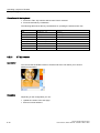
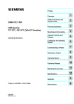
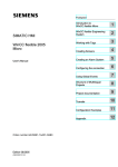
Principle
In the configuration settings of a recipe, you specify the behavior of the tags you are using in
the recipe. The figure below shows the basic differences when working with recipe data
records.
5-10
WinCC flexible 2005 Runtime
User's Manual, Edition 06/2005, 6AV6691-1BA01-0AB0
Runtime functionality
5.5 Recipes in Runtime
These configuration settings are made under "Settings" in the property view:
Configuration 1: Recipe without "Synchronize tags"
Data of a data record that has been read are only displayed and can only be edited in the
recipe view. Using these same tags outside of the recipe view does not affect their values.
Configuration 2: Recipe with "Synchronize tags" and with "Tags offline"
The "Synchronize tags" option is used to specify that the data of a data record read from the
controller or storage medium are to be written to or read from the tags you have configured
for the recipe.
The "Offline" option ensures that the input data are written to the tags without being
transferred directly to the controller.
Configuration 3: Recipe with "Synchronize tags" and without "Tags offline"
The "Synchronize tags" option is used to specify that the data of a data record read from the
controller or storage medium are to be written to or read from the tags you have configured
for the recipe.
The input or read data are transferred immediately to the controller:
Synchronization with the controller
In the case of synchronous transfer, both the controller and the HMI device set status bits in
the shared data compartment. You can use this mechanism to prevent uncontrolled
overwriting of data in either direction in your control program. You define the address range
of the data compartment separately for each controller on the "Range pointer" tab in the
"Connections" editor.
Applications for synchronous transfer of recipe data records:
• The controller is the "active partner" for the transfer of recipe data records.
• The controller evaluates the data containing the recipe number and name, as well as the
recipe data record number and name.
• Triggering the transfer of data records by means of system function or PLC job, e.g. with
the system functions "SetDataRecordToPLC" and "GetDataRecordFromPLC", or with the
PLC jobs "Set_Data_Record_To_PLC" and "Get_Data_Record_From_PLC."
WinCC flexible 2005 Runtime
User's Manual, Edition 06/2005, 6AV6691-1BA01-0AB0
5-11
Runtime functionality
5.5 Recipes in Runtime
In order to synchronize transfer of data records between the HMI device and the controller,
the following requirements must be met during configuration:
• The "Data mailbox" range pointer is located under "Range pointers" in the project view.
• The controller with which the HMI device synchronizes the data record transfer is
specified in the recipe properties.
5.5.4.3
Scenario: Entering recipe data records in Runtime
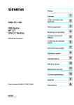
Objective
You want to enter production data on the HMI device without disturbing the process that is
currently underway. Therefore, the production data should not be transferred to the PLC.
Sequence
You enter the production data in the recipe view or the recipe screen, assign a recipe data
record name, and save the new recipe data record on the storage medium of the HMI
device.
5-12
WinCC flexible 2005 Runtime
User's Manual, Edition 06/2005, 6AV6691-1BA01-0AB0
Runtime functionality
5.5 Recipes in Runtime
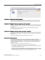
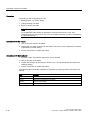
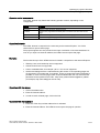
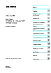
Configuration in WinCC flexible
You configure the recipe along with the associated tags.
Synchronization with the recipe tags is not necessary, because production data (tags) are
not intended to be transferred to the PLC. Make the following settings for the recipe in the
property view:
Depending on the extent of the recipe, you either configure a recipe view or create a recipe
screen.
5.5.4.4
Scenario: Manual production sequence
Objective
The production data are to be requested by the PLC according to the work piece to be
processed and displayed on the HMI device for inspection. You want to be able to correct
the transferred production data online, if necessary.
Sequence
WinCC flexible 2005 Runtime
User's Manual, Edition 06/2005, 6AV6691-1BA01-0AB0
5-13
Runtime functionality
5.5 Recipes in Runtime
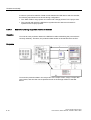
A reading device connected to the PLC reads a bar code on the work piece to be processed.
The recipe data record names correspond to the respective bar code names. This will enable
the PLC to load the necessary recipe data record from the storage medium of the HMI
device. The recipe data record is displayed for inspection. Changes are transferred
immediately to the PLC.
Configuration in WinCC flexible
You configure the recipe along with the associated tags.
Production data are to be transferred to the PLC, so it is necessary to synchronize with the
PLC to prevent the data from accidentally overwriting each other. The tags are to be
transferred to the PLC. Make the following settings for the recipe in the property view:
Depending on the extent of the recipe, you either configure a recipe view or create a recipe
screen.
5-14
WinCC flexible 2005 Runtime
User's Manual, Edition 06/2005, 6AV6691-1BA01-0AB0
Runtime functionality
5.5 Recipes in Runtime
5.5.4.5
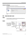
Scenario: Automatic production sequence
Objective
You want production to be executed automatically. The production data should be
transferred directly to the PLC either from the data storage medium in the HMI device or
from an external data storage medium. The production data do not have to be displayed.
Sequence
Production can be controlled using one or more "Scripts", which transfer production data
records automatically to the PLC. The sequence can be checked using the return values of
the utilized functions.
Configuration in WinCC flexible
You can implement the automatic production sequence with available system functions. The
"ImportDataRecords" system function loads data records from a CSV file to the data
medium. The "SetDataRecordTagsToPLC" system function transfers a data record from the
data storage medium to the PLC.
WinCC flexible 2005 Runtime
User's Manual, Edition 06/2005, 6AV6691-1BA01-0AB0
5-15
Runtime functionality
5.5 Recipes in Runtime
5.5.5
Displaying recipes
5.5.5.1
Viewing and editing recipes in Runtime
Introduction
The WinCC flexible ES offers you two configuration options of viewing and editing recipes
and their corresponding data records in Runtime on the HMI device:
• Recipes view
• Recipe screen
Recipes view
The recipe view is a screen object that is configured in the "Screens" editor. For example,
you can specify what operating function the recipe view will have in Runtime:
The recipe view shows recipe data records in tabular form. The Recipe view is particularly
useful if data records are small in size or only a few values are to be modified.
5-16
WinCC flexible 2005 Runtime
User's Manual, Edition 06/2005, 6AV6691-1BA01-0AB0
Runtime functionality
5.5 Recipes in Runtime
Simple recipe view
On HMI devices which have a display smaller than 6" (e.g. OP 77B), the simple Recipe view
is used to display and edit recipes.
The simple recipe view consists of three areas:
• Recipe selection
• RecipeDataRecordSelection
• Recipe entries
In the simple recipe view, each area is shown separately on the HMI device. The simple
recipe view always begins with the recipe selection.
Recipe screen
A recipe screen is a process screen with a customized input screen form that you create by
setting up input/output fields and other screen objects in the "Screens" editor. This makes it
possible for you to input parameter data in the context of machine visualization. The I/O
fields for a recipe can be distributed over multiple recipe screens, which allows you a topical
organization of recipe elements. The operating functions for the recipe screens must be
configured explicitly in the process screens.
WinCC flexible 2005 Runtime
User's Manual, Edition 06/2005, 6AV6691-1BA01-0AB0
5-17
Runtime functionality
5.5 Recipes in Runtime
5.5.5.2
Behavior of the recipe view in Runtime
Screen change
If you change to another screen and have not yet saved changes to the recipe data in the
recipe view, you will be prompted to save the recipe data. The recipe name and the name of
the recipe record are displayed to show which recipe data have not been saved yet.
If you change to a process screen that contains a recipe view with loaded recipe data, the
recipe data will be automatically updated.
Operating the recipe view with softkeys
The Recipe view can be operated with function keys, e.g. when the HMI device does not
have touch functionality. System functions allow you to assign functions such as "Save data
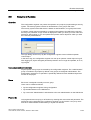
record" to the function keys of the HMI device.
Display after import of recipe data
If you open the recipe view during the import of recipe data, only the recipe data that is
already completely imported will be displayed. The recipe view is not automatically updated
with a data import. In order to have a complete view of all recipe data, only open the recipe
view after the system alarm informs you that the import of recipe data was successful.
Alternatively, update the recipe view after successful completion of the import procedure.
5.5.6
Recipe data record administration
5.5.6.1
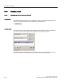
Recipe data record administration
Recipe data record administration
In Runtime you can, based on the configuration
• Create new recipe data records
• Copy recipe data records
• Edit recipe data records
• Delete recipe data records
That is, you can either edit recipe data records in the recipe view or screen, or import recipe
data records from a CSV file.
5-18
WinCC flexible 2005 Runtime
User's Manual, Edition 06/2005, 6AV6691-1BA01-0AB0
Runtime functionality
5.5 Recipes in Runtime
Creating new recipe records
1. Select the recipe on the HMI device in which you want to create a new recipe data
record.
2. Use the "Add data record" button in the recipe view or the corresponding button on the
HMI device that has this function.
A new data record with the next available number will be created. If you change the new
data record number of an existing data record number, the data record is overwritten.
3. Enter a name for the recipe data records.
4. Enter the values for the recipe data records.
The configuration data may already contain default values for the recipe data record.
5. Use the "Save" button in the recipe view or the corresponding button on the HMI device
that has this function.
Result
The new recipe data records will be saved to the selected recipe. If the recipe data records
already exists, a system alarm will be output to the screen.
Copying a recipe data record
You copy a recipe record by saving it under a new name.
1. Select the recipe on the HMI device in which you want to edit an existing recipe data
record.
2. Select the recipe data record that you want to edit on the HMI device.
3. Assign a new name to the recipe data record.
As soon as you close the "Recipe data record" input field, the next free recipe data record
number will be automatically assigned to the recipe data record. You may change the
recipe data record number.
4. Use the "Save" button in the recipe view or the corresponding button on the HMI device
that has this function.
Result
The recipe data record is stored under the new name.
Modify recipe record
1. Select the recipe on the HMI device in which you want to edit an existing recipe data
record.
2. Select the recipe data record that you want to edit on the HMI device.
3. Replace the old values with new ones.
4. Use the "Save" button in the recipe view or the corresponding button on the HMI device
that has this function.
WinCC flexible 2005 Runtime
User's Manual, Edition 06/2005, 6AV6691-1BA01-0AB0
5-19
Runtime functionality
5.5 Recipes in Runtime
Result
The modified values are applied to the recipe data record.
Delete recipe data record
1. Select the recipe on the HMI device in which you want to delete an existing recipe data
record.
2. Select the recipe data record that you want to delete on the HMI device.
3. On the recipe view, select "Delete data record", or use the relevant HMI device button
which is assigned this function.
Result
The recipe data record is deleted from the data medium of the HMI device.
5.5.6.2
Synchronizing a recipe data record
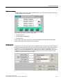
Introduction
In the current project, differences between the indicated values and the actual values of the
recipe tags may arise as a result of data input in recipe views or modification of recipe tags.
Depending on the configuration, you can synchronize the values displayed in the recipe view
with the recipe tags and values of the PLC. This synchronization is performed for each one
of the recipe tags contained in the recipe data record.
Requirement
A recipe data record is displayed in the recipe view. The value of recipe tags can be
changed, for example by teach-ins.
Procedure
1. Use the "Synchronization with control" button in the recipe view or the corresponding
button that has this function.
Result
• The system always updates the current value of the recipe view with the up-to-date
recipe tag value.
• When the value shown in the recipe view is more recent than the current recipe tag value,
the system writes this value to the recipe tag.
5-20
WinCC flexible 2005 Runtime
User's Manual, Edition 06/2005, 6AV6691-1BA01-0AB0
Runtime functionality
5.5 Recipes in Runtime
5.5.6.3
Read recipe data record from PLC
Introduction
You can read values from the PLC and write them to a recipe data record. For example, you
can do this in machine teach-in mode in order to save the positioning data of axes as a
recipe data record.
The read values are written to the recipe record that is currently displayed on the HMI
device.
Procedure
1. Select the recipe on the HMI device.
2. On the HMI device, select the recipe data record of which you want to fetch the values
from the PLC.
3. Use the "Read from PLC" button in the recipe view or the corresponding button on the
HMI device that has this function.
4. Use the "Save" button in the recipe view or the corresponding button on the HMI device
that has this function.
Result
The values are read from the PLC, visualized on the HMI device and saved to the recipe
data record.
5.5.6.4
Transfer recipe record to PLC
Introduction
You can edit recipes offline or online.
• Offline: The data are transferred to the PLC after the relevant command is executed.
• Online: The data are transferred immediately to the PLC
In the recipe view, data are always edited offline. The configuration of the recipe screen
determines whether the recipe data are edited offline or online.
When you edit data offline, you have to transfer the changed data to the PLC.
Procedure
1. Select the recipe on the HMI device.
2. On the HMI device, select the recipe data record of which you want to transfer the values
to PLC.
3. Use the "Write to PLC" button in the recipe view or the corresponding button on the HMI
device that has this function.
Result
The values of the recipe record are transferred to the PLC.
WinCC flexible 2005 Runtime
User's Manual, Edition 06/2005, 6AV6691-1BA01-0AB0
5-21
Runtime functionality
5.5 Recipes in Runtime
5.5.6.5
Exporting and importing recipe data records
Introduction
Based on your configuration, you can either export recipe data records to a CSV file for
editing in MS Excel, for example, or import these from a CSV file. The extent to which you
can influence these processes is determined by the project configuration. Various input fields
may be configured on the user interface:
• Input of the path to the CSV file
• Selection of the recipe data records for export
• Overwriting an existing CSV file
Export recipe data record
Requirements
Export functions are configured.
Procedure
1. Customize the export settings on the user interface of the HMI device.
2. Press the button or the key on the HMI device configured with the "Export recipe records"
function.
Result
The recipe data record are exported to a CSV file.
Note
New data records created in runtime can be exported to an external file.
Importing recipe records
Requirements
Import functions are configured.
Procedure
1. Customize the import settings on the user interface of the HMI device.
2. Use the button or the key on the HMI device which is assigned the "Import recipe
records" function.
5-22
WinCC flexible 2005 Runtime
User's Manual, Edition 06/2005, 6AV6691-1BA01-0AB0
Runtime functionality
5.5 Recipes in Runtime
Result
The recipe data record are imported. If the structure of the CSV file is different from the
recipe structure, deviations are treated as follows:
• Any additional values in the CSV file will be rejected.
• If the CSV file contains values of the wrong data type, the configured default value is set
in the recipe record.
Example:
The CSV file contains values that show the tank contents and were input as floating point
numbers. However, the corresponding recipe tag expects an integer value. In this case,
the system discards the imported value and uses the configured default.
• The system also applies the configured default value to the recipe data record if the CSV
file contains an insufficient number of values.
5.5.6.6
Reactions to modifications of the recipe structure
Introduction
Engineering for the purpose of machine retrofitting may also influence the recipe structure.
Previously created recipe data records can nevertheless continue to be used.
Effects
If the structure of the recipe record is different from the defined address ranges in the PLC,
deviations are handled as follows:
• Any additional values in the recipe record will be rejected.
• If the recipe record contains values of the incorrect data type, the default will be used in
the recipe record.
Example: The recipe record contains values that show the tank contents and were input
as floating point numbers. However, the corresponding recipe tag expects an integer
value. In this case, the transferred value is rejected and the default value is used.
The system also applies the default value to the recipe data record, if the recipe data
record contains an insufficient number of values.
Caution
When a tag is renamed, the assignment is lost.
WinCC flexible 2005 Runtime
User's Manual, Edition 06/2005, 6AV6691-1BA01-0AB0
5-23
Runtime functionality
5.5 Recipes in Runtime
5.5.7
Example
5.5.7.1
Example: Creating a recipe
Task
In this example, you create three recipes for a fruit juice mixing machine. The fruit juice
mixing machine is to be used to produce orange, apple, and tropical fruit flavors, based on
mixing ratios for fruit drinks, nectar, and juice.
Settings
The settings relate to an HMI device which is connected to a SIMATIC S7-300 or SIMATIC
S7-400 via MPI.
In this example, you need the following tags, flags, recipes, and recipe data record values:
Tags:
Name
PLC connection
Address
Type
Liter water
yes
DB 120, DBW 0
Integer
Liter concentrate
yes
DB 120, DBW 4
Integer
Kilo sugar
yes
DB 120, DBW 8
Integer
Gram flavoring
yes
DB 120, DBW 12
Integer
Flag:
Name
Address
Data set
DB 100, DBW 0
Recipe (basic settings):
Recipe element
Associated tag
Liter water
Liter water
Liter concentrate
Liter concentrate
Kilo sugar
Kilo sugar
Gram flavoring
Gram flavoring
Recipe data record values:
5-24
Data record name
Liter water
Liter concentrate
Kilo sugar
Gram flavoring
Fruit drink
30
70
45
600
Nectar
50
50
10
300
Juice
5
95
3
100
WinCC flexible 2005 Runtime
User's Manual, Edition 06/2005, 6AV6691-1BA01-0AB0
Runtime functionality
5.5 Recipes in Runtime
Procedure
1. Create the following tags with the settings indicated earlier: Liter water, Liter concentrate,
Kilo sugar and Gram flavoring.
2. Create the orange, apple, and tropical fruit recipes with the settings indicated above.
3. Configure each recipe in such a way that you can edit the recipe data records on a recipe
screen. The values of the recipe tags should not be transferred automatically to the PLC.
4. Create the data records indicated above in each recipe. Enter the values indicated above
in each of the data records.
Result
The orange, apple, and tropical fruit flavor recipes have been created. In the "Configure
recipe screen" example, you create a recipe screen in which you create an individual input
screen form.
WinCC flexible 2005 Runtime
User's Manual, Edition 06/2005, 6AV6691-1BA01-0AB0
5-25
Runtime functionality
5.5 Recipes in Runtime
5.5.7.2
Example: Configuring a recipe screen
Task
In this example, you create a recipe screen for the visualization of values of the fruit juice
mixing machine. You use a recipe view to select the recipes and their associated recipe data
records. You should be able to load and save the values of the recipe data records, and
transfer them to and read them from the PLC.
Requirements
The "Creating a recipe" sample application has been carried out.
The "Fruit juice mixing machine" process screen has been created and is opened.
Settings
In this example, you need the following tags and buttons with the indicated settings:
Tags:
Name
PLC connection
Type
RecipeNumber
NO
Integer
Data record number
NO
Integer
Buttons:
5-26
Labeling
Configured event
System function
Downloading
Press
LoadDataRecord
Save
Press
SaveDataRecord
Data to PLC
Press
SetDataRecordTagsToPLC
Data from the PLC
Press
GetDataRecordTagsFromPLC
WinCC flexible 2005 Runtime
User's Manual, Edition 06/2005, 6AV6691-1BA01-0AB0
Runtime functionality
5.6 Reports in Runtime
Procedure
1. Drag-and-drop the "Liter water", "Liter concentrate", "Kilo sugar", and "Gram flavoring"
tags from the object view to the "Fruit juice mixing machine" process screen.
Four I/O fields are created and linked by the specified tags.
2. Configure a recipe view containing only the drop-down lists for the recipe name and data
record name. Link the recipe view to the "Recipe number" and "Data record number"
(recipe data record number) tags in the "General" group in the property view.
3. Assign the settings described above to each one of the four buttons. Transfer each
"Recipe number" and "Data record number" tag as a parameter for the recipe number
and recipe data record number.
Result
In Runtime, you can select the recipe and the associated recipe data record from the recipe
view. Click "Load" to load the recipe data record values and display these in the configured
I/O fields. Click "To PLC" to write the recipe data record values to the associated tags and to
transfer the recipe data record values to the PLC.
5.6
5.6
Reports in Runtime
Overview
Logs are used to document process data and completed production cycles. The log content
and layout are specified in the project, as is the event triggering the printout of the report.
For example, a log can be configured for output at the end of a shift, in order to record
downtimes. A log can also be configured for the purpose of the documentation of product
testing or quality inspections (ISO 9000).
Output
Reports are printed in Runtime either automatically, e.g. by means of a scheduler, or
manually, e.g. by means of a softkey.
Printing reports
Reports are output to the printer in graphic mode. The use of a serial printer is not
recommended because of the accumulated data volume.
For proper output, the printer must support the paper format and page layout of the report.
Note
The value of a tag in the report is read and output at the moment of printing. A substantial
time may elapse between printing out the first and the last page of a report consisting of
several pages. This may lead to the same tag on the last page being output with a different
value from that on the first page.
WinCC flexible 2005 Runtime
User's Manual, Edition 06/2005, 6AV6691-1BA01-0AB0
5-27
Runtime functionality
5.7 System functions and scripts in Runtime
5.7
5.7
System functions and scripts in Runtime
Application
System functions and scripts are used in Runtime for the following purposes:
• To control the process
• To utilize the properties of the HMI device
• To make system settings online on the HMI device
In WinCC flexible, each system function and each script is linked to an object, such as a
button, field or screen, and an event. As soon as the event occurs, the system function is
triggered.
System functions
System functions are predefined functions that are used to implement many tasks in
Runtime, such as:
• calculations, e.g. increasing a tag value by a specific or variable amount
• Logging function, e.g. starting a process value log
• Settings, e.g. changing the PLC or setting a bit in the PLC.
• Alarms, e.g after a different user logs on.
Scripts
Scripts may also be included in the project for specific applications which may require
additional functions. For the creation of scripts, WinCC flexible provides an interface to
Microsoft Visual Basic Script (VBScript). This allows you to integrate additional functions,
such as:
• conversion of values, e.g. between different physical units (temperatures)
• Automation of production sequences
A script can control a production sequence by transferring production data to a PLC. The
status can be checked based on the returned values, and appropriate measures can thus
be initiated.
Events
The object and the selected function determine what events can be defined as triggers for
executing a system function.
For example, the events "Change Value", "Below Lower Limit" and "Above Upper Limit" are
associated with the "Tag" object. The "Loaded" and "Cleared" events are associated with the
"Screen" object.
5-28
WinCC flexible 2005 Runtime
User's Manual, Edition 06/2005, 6AV6691-1BA01-0AB0
Runtime functionality
5.8 Security in Runtime
5.8
5.8
Security in Runtime
Overview
The configuration engineer can protect the operation of a project by implementing a security
system. The security system is based on authorizations, user groups and users.
The security system of the HMI device is based on authorizations, user groups and users.
If operator control objects protected by a password are operated, the HMI device requests
the entry of a password. A login screen is displayed in which you enter your user name and
password. After logging in, you can operate the operator control objects for which you have
the necessary authorizations.
The login dialog can be set up by the configuration engineer via an individual operator
control object.
In the same way, the configuration engineer can set up an operator control object to log off.
After logging off, objects assigned password protection can no longer be operated; to do so,
log in again.
User groups and authorizations
Project-specific user groups are created by the configuration engineer. The "Administrators"
group is included in all projects by default. User groups are assigned authorizations. The
authorization required for an operation is specifically defined for each individual object and
function in the project.
Users
Each user is assigned to exactly one user group.
Users can be created as follows:
• By the configuration engineer during configuration
• By the administrator on the HMI device
• By a user with "Administration" authorization to the user administration on the HMI device
Passwords
Only registered users may log on to Runtime by entering their user name and password. The
passwords can be assigned by the configuring engineer, by the "Admin" user (or by users
who have "Administration" authorization), or by the user himself.
WinCC flexible 2005 Runtime
User's Manual, Edition 06/2005, 6AV6691-1BA01-0AB0
5-29
Runtime functionality
5.8 Security in Runtime
The authorizations of a user after logging in depends on the user group to the user is
assigned.
After the project is transferred, only the administrator is authorized to create user accounts,
make user group assignments, and change passwords. Any other users who are
subsequently assigned to the "Administrator" group by the administrator may also carry out
these tasks.
The user data is encrypted and saved on the HMI device to protect it from loss due to power
failure.
Note
Depending on the transfer settings, changes to the user data are overwritten when the
project is transferred again.
Logoff times
A logoff time is specified in the system for each user. If the time between any two user
actions, e.g, entering a value or changing screens, exceeds this logoff time, the user is
automatically logged off. The user must then log in again to continue to operate objects
assigned password protection.
User view
Use the User view to display the users on the HMI device.
Export and import
The users, passwords, group assignments and logoff times established on the HMI device
can be exported and then imported on a different HMI device. This prevents you having to
enter all of the data again on another HMI device.
Notice
When importing, the currently valid user data is overwritten. The imported user data and
passwords are valid immediately.
5-30
WinCC flexible 2005 Runtime
User's Manual, Edition 06/2005, 6AV6691-1BA01-0AB0
Runtime functionality
5.9 Further operating options in Runtime
5.9
5.9
Further operating options in Runtime
Print functions
Print functions available in online mode: :
• Hardcopy
You can print the content of the currently displayed screen if you utilize the "Print screen"
system function in your configuration.
• Printing alarms
Each alarm event that occurs (incoming, outgoing, acknowledgment) is also sent to a
printer.
• Printing reports
LED control
The light-emitting diodes (LED) in the function keys of the SIMATIC HMI devices can be
controlled from the PLC. For example, an illuminated or flashing LED can signal the operator
to press a specific function key on the device.
WinCC flexible 2005 Runtime
User's Manual, Edition 06/2005, 6AV6691-1BA01-0AB0
5-31
Runtime functionality
5.9 Further operating options in Runtime
5-32
WinCC flexible 2005 Runtime
User's Manual, Edition 06/2005, 6AV6691-1BA01-0AB0
Operating a project in Runtime
6.1
6.1.1
6.1
6
Basics for operation in Runtime
Introduction
Introduction
Operation of a process depends on how the project was created and the options available on
the HMI device. This chapter contains general information on the settings for the Runtime
software and the operation of predefined screen objects.
Screen objects provide general system functions. Screen objects may have been used and
configured in screens of the project.
WinCC flexible Runtime can be operated with the keyboard, mouse or touch screen,
depending on the HMI device used.
Multiple key operation
If you are using a key device, you can press two function keys at once.
Caution
When you use a key device, you may not press more than two function keys simultaneously.
If you use a touch device, standard PC or a panel PC, you may only press one function key
or button at a time.
In both cases, pressing too many keys may be inadvertently trigger actions.
Change language
WinCC flexible allows you to configure a multilingual project. Up to five of these project
languages can be loaded simultaneously onto the HMI device.
You can switch between the individual languages in Runtime, provided this function has
been configured. When languages are switched, the language-dependent objects such as
texts or formats are displayed in another language.
WinCC flexible 2005 Runtime
User's Manual, Edition 06/2005, 6AV6691-1BA01-0AB0
6-1
Operating a project in Runtime
6.1 Basics for operation in Runtime
Objects that may contain language-relevant texts include:
• Alarms
• Screens
• Text lists
• Operator notes
• Recipes
• Date/time
• Decimal symbol
• Static texts
Pictograms
HMI devices with integrated keyboard (e.g. Panel PC 670) may by configured with
pictograms on the bottom and on the left / right screen margins.
Pictograms are used to clarify the screen-specific functions of the function keys. Use the
associated function key to trigger the function symbolized by the pictogram.
6.1.2
Operation with mouse and keyboard
Operation with the keyboard
The navigation options listed in the table can be used for keyboard operations in a screen.
Navigation
PC
SIMATIC Panel PC
Next field right/left
<Shift+Right> / <Shift+Left>
<Right> / <Left>
Next field up/down
<Shift+Down> / <Shift+Up>
<Down> / <Up>
To the right/left in the
field
<Right> / <Left>
<Shift+Right> / <Shift+Left>
The other keys have identical functions on the PC and the SIMATIC Panel PC:
Key
Function
<Enter>
Applies a value (e.g. in unmarked input fields) or opens a selection list.
If the I/O field is marked (highlighted in color), WinCC flexible Runtime will
switch to the special editing mode. Now, only one character will be marked in
the field.
Use the cursor keys <Up>/<Down> to scroll through a character table.
Use the cursor keys Right/Left to move the cursor to the next or previous entry
position.
Press <Enter> or <Esc> to exit from the entry mode. The characters entered up
to this point will be either applied or discarded.
6-2
<Esc>
Interrupts the input.
<Tab>
Selects the next available screen object in the configured tab sequence.
<Shift+Tab>
Selects the previously available screen object in the configured tab sequence.
WinCC flexible 2005 Runtime
User's Manual, Edition 06/2005, 6AV6691-1BA01-0AB0
Operating a project in Runtime
6.1 Basics for operation in Runtime
Key
Function
<F1> -... <F12>,
<Shift+F1>, ...,
<Shift+F12>
On the PC: Triggers a function, e.g. screen selection.
<F1>, ... or <S1>,
... or <K1>, ...
On the SIMATIC Panel PC: triggers a global or local function.
Caution
If you press a function key after a screen change, the associated function in the new screen
may be triggered before the new screen is fully displayed.
Controlling Windows with the keyboard
You may also use the keyboard to control the operating system of your HMI device. See
your Windows manual for detailed information. The most important key combinations for
SIMATIC Panel PCs are listed in the following table.
Navigation
HMI device
Open start menu
<Ctrl+Esc>
Show the shortcut menu of the selected element
<Shift+F10>
Select all
<Ctrl+A>
Display properties of the selected element
<Ctrl+Enter>
Explorer:
Change folder
<F4>
Change display areas
<F6>
Enable menu bar
<F10>
Dialogs:
Go to next field
<Tab>
Back to previous field
<Shift+Tab>
Open next tab
<Ctrl+Tab>
Open previous tab
<Ctrl+Shift+Tab>
Operation with the mouse
A lightning symbol attached to the mouse pointer indicates that the screen object, for
example a switch, may be operated with the mouse.
WinCC flexible 2005 Runtime
User's Manual, Edition 06/2005, 6AV6691-1BA01-0AB0
6-3
Operating a project in Runtime
6.1 Basics for operation in Runtime
6.1.3
Operating the touch screen device
6.1.3.1
Operating touch objects
Operation
Touch objects represent touch-sensitive operator control objects on the HMI screen such as
buttons, I/O fields and alarm windows. Touch objects are basically operated in the same way
as conventional keys. You operate touch objects by touching them with your finger.
Caution
Never touch more than one object on the screen. Do not touch several touch objects
simultaneously. Otherwise, you can trigger an unintended action.
Caution
Do not use any pointed or sharp objects when operating the touch screen in order to avoid
damage to its plastic screen membrane.
Direct keys
With a PROFIBUS DP connection, it is also possible to configure buttons for operation as
direct keys in order to allow rapid operator inputs using keys. For example, jog mode
requires rapid operator inputs using keys.
PROFIBUS-DP direct keys place bits directly from the HMI device in the I/O area of a
SIMATIC S7.
Note
Direct keys can only be triggered by touch and not by a mouse click from an connected
external USB mouse.
Note
With touch operation, direct keys are triggered independent of any configured password
protection.
Notice
Direct keys are still active when the HMI device is in "offline" mode.
Operation feedback
The HMI device responds with visual and auditory feedback as soon as it detects the
operation of a touch object. This feedback is independent of any communication with the
PLC. Therefore, this feedback does not indicate whether the relevant action is actually
executed or not.
6-4
WinCC flexible 2005 Runtime
User's Manual, Edition 06/2005, 6AV6691-1BA01-0AB0
Operating a project in Runtime
6.1 Basics for operation in Runtime
Acoustic acknowledgement
The HMI device outputs a beep to signal operation of a touch object. You can disable this
beep.
Optical feedback
The type of optical feedback depends on the operator control object:
• Buttons
The HMI outputs different views of the "Touched" and "Untouched" states, provided the
configuration engineer has configured a 3D effect:
Touched
Untouched
The configuring engineer defines the appearance of a selected field (line width and color
for the focus).
• Invisible buttons
The focus of hidden buttons is not marked after selection (focus width value is 0, default).
In Runtime, the outline of a touched button is indicated as a line when you modify the
value for the focus width in the configuration. This outline remains visible until the focus is
set on another operating object.
• I/O fields
After you touch an I/O field, a screen keyboard appears as feedback.
Operating screen objects with buttons
Screen objects with predefined buttons can also be operated with external buttons. To do so,
the corresponding system functions must have been linked to this button by the configuring
engineer.
In WinCC flexible, these system functions are compiled in the "Keyboard actions for screen
objects" group.
6.1.3.2
Input of values
Screen keyboard
The HMI device automatically opens the screen keyboard when you touch an input object
such as an I/O field. This screen keyboard is also displayed to input of passwords for access
to protected functions. The keyboard is automatically hidden again when input is complete.
Based on the configuration of the input object, the HMI device shows a screen keyboard only
for the input of numeric or alphanumeric values.
The screen keyboard is activated by selecting an input object in runtime.
WinCC flexible 2005 Runtime
User's Manual, Edition 06/2005, 6AV6691-1BA01-0AB0
6-5
Operating a project in Runtime
6.1 Basics for operation in Runtime
6.1.3.3
Entering alphanumeric values
Alphanumerical screen keyboard
The HMI device automatically opens an alphanumeric on-screen keyboard for inputting
character strings and numeric values in hexadecimal format when you touch an input object
on the touch screen. The keyboard is automatically hidden again when input is complete.
The <Help> key is only active if an operator note has been programmed for the input object.
Keyboard layers
The alphanumerical keyboard is organized in several layers:
• Standard layer (see the figure)
• <Shift> layer
• <Alt Gr> layer
• <Shift+Alt Gr> layer
The <Alt Gr> and <Shift+Alt Gr> layers are used for the input of special characters.
Procedure
You enter alphanumeric values character-by-character using the on-screen keyboard
buttons. Confirm the input value with <Enter>, or cancel it with <Esc>. Both actions close the
screen keyboard.
6-6
WinCC flexible 2005 Runtime
User's Manual, Edition 06/2005, 6AV6691-1BA01-0AB0
Operating a project in Runtime
6.1 Basics for operation in Runtime
6.1.3.4
Entering numeric values
Numerical screen keyboard
The HMI device automatically opens the numerical touch screen keyboard for entering
numerical values when you touch an I/O field. The keyboard is automatically hidden again
when input is complete.
The <Help> button is only active if an operator note is configured for the I/O field.
Procedure
You enter the characters of numeric values using the screen keyboard buttons. Confirm the
input value with <Enter>, or cancel it with <Esc>. Both actions close the screen keyboard.
Note
Limit values can be configured for numeric input fields. In this case, values are only
accepted if they lie within configured limits. If you enter a value that is outside the configured
limits, the system rejects this value and restores the original. The HMI outputs a system
alarm to indicate this situation.
When you enter the first character, a tooltip appears showing the hi and lo limit values of the
input field.
WinCC flexible 2005 Runtime
User's Manual, Edition 06/2005, 6AV6691-1BA01-0AB0
6-7
Operating a project in Runtime
6.1 Basics for operation in Runtime
6.1.3.5
Calling the infotext
Purpose
The configuring engineer uses operator notes to provide additional information and operating
instructions with respect to alarms, screens, and operable screen objects. For example, an
operator note may contain information about the permissible range of values for an I/O field,
or information on the cause and remedy of a fault in the event of an error alarm.
Help on messages
Press
in the alarm window or in the alarm view.
Help on input objects
Touch the <Help> button on the on-screen keyboard. This button is only available if you
configured an operator note.
Help on the current screen
If, for example, the "ShowOperatorNote" function is assigned to a button in your
configuration, you can call the configured operator note for the current screen by pressing
this button.
Help on the focused screen object
Use the <Alt+H> key combination on the screen keyboard or on the connected USB
keyboard to display the operator notes configured for the focused screen object.
Note
To view a new operator note, you first need to close the window showing the current
operator note.
6-8
WinCC flexible 2005 Runtime
User's Manual, Edition 06/2005, 6AV6691-1BA01-0AB0
Operating a project in Runtime
6.2 Operating graphic objects
6.2
6.2.1
6.2
Operating graphic objects
Button
Application
A button is a virtual key on the screen of the HMI device that can have one or more
functions.
Layout
The layout of the button depends on the button type.
• Button with text: The text shown on the button gives information regarding the status of
the button.
• Button with graphic: The graphic shown on the button gives information regarding the
status of the button.
• Invisible: The button is not visible in Runtime.
Operation
Depending on the configuration, you can operate the button in the following ways:
• Standard operation: Click the button.
• Event: An event is triggered when you operate the button, e.g. when you click it. The
processing of a function list can be configured to the event.
Operation behavior
The operation may be followed with a optical feedback. However, note that the optical
feedback only indicates a completed operation and not whether the configured functions
were actually executed.
Operation with the mouse
1. Click on the button with the mouse pointer.
Operation with the keyboard
1. Press the <Tab> key until the button is selected.
2. Press <Enter> or <Space Bar>.
WinCC flexible 2005 Runtime
User's Manual, Edition 06/2005, 6AV6691-1BA01-0AB0
6-9
Operating a project in Runtime
6.2 Operating graphic objects
Alternative operation
Depending on the configuration, you can also operate the button via the function keys.
Operation behavior
The behavior depends on the configuration.
Button with text, button with graphic
The operation may be followed with a optical feedback.
6.2.2
Switch
Application
The switch is an operating element and display object with two states: "pressed" and
"released." Switches can signal the state of a system component that cannot be seen from
the HMI device, e.g. a motor. You can also change the state of that system component at the
HMI device.
Layout
The layout of the switch depends on the switch type.
• Switches: The switch has a slider. The position of this slider gives information about the
status of the switch.
• Switch with text: The text shown on the switch gives information regarding the status of
the switch.
• Switch with graphic: The graphic shown on the switch gives information regarding the
status of the switch.
Operation
Depending on the configuration, you can operate the switch in the following ways:
• Standard operation: Click the switch.
• Event: An event is triggered when you operate the switch, e.g. when you click it. The
processing of a function list can be configured to the event.
6-10
WinCC flexible 2005 Runtime
User's Manual, Edition 06/2005, 6AV6691-1BA01-0AB0
Operating a project in Runtime
6.2 Operating graphic objects
Operation behavior
A switch has two stable states: When you activate the switch, it changes to the other state.
The switch retains this state until the next operation.
Operation with the mouse
The behavior depends on the configuration.
Switch with slider
1. Click on the slider.
2. While holding down the mouse button, drag the slider to the other position.
Switch with text, switch with graphic
1. Click on the switch.
Operation with the keyboard
1. Press the <Tab> key until the switch is selected.
2. Press <Enter> or <Space Bar>.
Operation behavior
The behavior depends on the configuration.
Switch with slider
The slider jumps to the other position.
Switch with text, switch with graphic
The switch changes the status.
WinCC flexible 2005 Runtime
User's Manual, Edition 06/2005, 6AV6691-1BA01-0AB0
6-11
Operating a project in Runtime
6.2 Operating graphic objects
6.2.3
IO field
Application
You enter numeric or alphanumeric values in an I/O field. For example, a numeric value
could be the number 80 as a temperature reference, an alphanumeric value could be the text
"Service" as a user name.
Layout
The layout of the I/O field depends on the configuration:
• Numeric I/O field
For input of numbers in decimal, hexadecimal or binary format.
• Alphanumeric I/O field
For input of character strings.
• I/O field for date and time
For input of calendar dates or time information. The format depends on the set
configuration.
• I/O field for password entry
For concealed entry of a password. The entered character string is displayed with
placeholders (*).
Operation
Depending on the configuration, you can operate the I/O field in the following ways:
• Standard operation: Enter a value in the I/O field.
• Event: An event is triggered when you operate the I/O field, e.g. when you activate it. The
processing of a function list can be configured to the event.
Operation behavior
Limit value test of numerical values
Tags can be assigned limit values. The entered value is then only accepted if the value lies
within the configured limits.
If an entered value exceeds a configured limit value, e.g. 80 with a limit value 78, the entered
value is rejected. If an alarm window is configured, then a system alarm is displayed
automatically.
6-12
WinCC flexible 2005 Runtime
User's Manual, Edition 06/2005, 6AV6691-1BA01-0AB0
Operating a project in Runtime
6.2 Operating graphic objects
Decimal places for numerical values
If a numeric input field is configured with a specific number of decimal places, decimal places
in excess of the limit are ignored. Empty decimal places are filled with "0" after the number is
confirmed.
Hidden input
With the hidden input, each character entered is displayed as an "*" character. The data
format of the value entered cannot be recognized.
Operation with the mouse
1. Click in the I/O field with the mouse pointer.
2. Type in the relevant value.
3. Confirm your input with <Enter> or cancel it with <Esc>.
Operation with the keyboard
1. Press the <Tab> key until the I/O field is selected.
2. Set the value.
3. Confirm your input with <Enter> or cancel it with <Esc>.
Alternative operation with the keyboard
1. Press the <Tab> key until the I/O field is selected.
2. Press <Return>. The object changes to the specific editing mode. Now, only one
character will be marked in the field.
3. Use the <Up>/<Down> cursor keys to scroll through a character table.
4. Use the <Right>/<Left> cursor keys to move the cursor to the next or previous input
position.
5. Confirm your input with <Enter> or cancel it with <Esc>.
WinCC flexible 2005 Runtime
User's Manual, Edition 06/2005, 6AV6691-1BA01-0AB0
6-13
Operating a project in Runtime
6.2 Operating graphic objects
6.2.4
Graphic I/O field
Application
A graphic I/O field can have the following Runtime functions:
• Output of graphic list entries
• Combined entry and output
Example of its use as output field:
To indicate the Runtime status of a valve, the graphic I/O field outputs the image of a closed
or open valve.
Operation
Depending on the configuration, you can operate the graphic I/O field in the following ways:
• Standard operation: Select an entry from the graphic list.
• Event: An event is triggered when you operate the graphic I/O field, e.g. when you
activate it. The processing of a function list can be configured to the event.
Operation behavior
If the graphic I/O field displays a cactus image, you have not defined a graphic to be output
for a specific value in your project.
The contents of the graphic I/O field change color to show that it is now activated.
Operation with the mouse
1. Click on the graphic I/O field. The selection list opens.
2. Click on the scroll bar with the mouse pointer. Move the scroll bar in the desired direction
while holding down the left mouse button.
3. Select the desired entry. The selection list is closed and the entry is displayed.
Operation with the keyboard
1. Press the <Tab> key until the graphic I/O field is selected.
2. Press <Enter>. The selection list opens.
3. Select the desired entry from the selection list. Toggle between the next or previous entry
by using the cursor keys <Left>, <Right>, <Up> and <Down>.
4. Confirm your input with <Enter> or cancel it with <Tab> or <Esc>.
6-14
WinCC flexible 2005 Runtime
User's Manual, Edition 06/2005, 6AV6691-1BA01-0AB0
Operating a project in Runtime
6.2 Operating graphic objects
6.2.5
Symbolic IO field
Application
A symbolic I/O field can have the following Runtime functions:
• Output of text list entries
• Combined entry and output
Example of its use as combination I/O field:
To control a motor in Runtime, the operator selects the text "Motor OFF" or "Motor ON" from
the text list. The motor is then started or stopped in accordance with the selection. The
symbolic I/O field displays the respective status of the motor.
Operation
Depending on the configuration, you can operate the symbolic I/O field in the following ways:
• Standard operation: Select an entry from the text list.
• Event: An event is triggered when you operate the symbolic I/O field, e.g. when you
activate it. The processing of a function list can be configured to the event.
Operation behavior
If the symbolic I/O field contains a blank text line in the selection list, no entries have been
defined in the project. The contents of the symbolic I/O field change color to show that it is
now activated.
Operation with the mouse
1. Left mouse click on the symbolic I/O field. The selection list opens.
2. Click on the scroll bar with the mouse pointer. Move the scroll bar in the desired direction
while holding down the left mouse button.
3. Select the desired entry with the left mouse button. The selection list is closed and the
entry is displayed.
Operation with the keyboard
1. Press the <Tab> key until the symbolic I/O field is selected.
2. Press <Enter>. The selection list opens.
3. Select the desired entry from the selection list. Toggle between the next or previous entry
by using the cursor keys <Left>, <Right>, <Up> and <Down>.
4. Confirm your input with <Enter> or cancel it with <Tab> or <Esc>.
WinCC flexible 2005 Runtime
User's Manual, Edition 06/2005, 6AV6691-1BA01-0AB0
6-15
Operating a project in Runtime
6.2 Operating graphic objects
6.2.6
Alarm indicator
Application
During Runtime, the alarm indicator is displayed if alarms of the specified alarm class are
pending or require acknowledgement.
Layout
The alarm indicator can have one of two states:
• Flashing: At least one unacknowledged alarm is pending.
• Static: The alarms are acknowledged but at least one of them is not yet deactivated.
Operation
The icons from the symbol library can only be operated with a mouse or touch screen.
Depending on the configuration, you can operate the alarm indicator in the following ways:
• Standard operation: Activate the alarm indicator.
• Event: An event is triggered when you operate the alarm indicator, e.g. when you click it.
The processing of a function list can be configured to the event.
Operation behavior
Depending on the configuration, when operating the alarm indicator an alarm window is
opened.
Operation with the mouse
1. Click on the alarm indicator with the mouse pointer. Depending on the configuration, the
alarm window is opened.
2. Use the Close icon to close the Alarm window and be able to operate the screens. The
alarm window can be opened again by clicking on the alarm indicator.
6-16
WinCC flexible 2005 Runtime
User's Manual, Edition 06/2005, 6AV6691-1BA01-0AB0
Operating a project in Runtime
6.2 Operating graphic objects
6.2.7
Alarm view
Application
The alarm view shows selected alarms or events from the alarm buffer or alarm log.
Layout
Depending on the configuration, in the alarm view different columns with information
regarding an alarm or an alarm event are displayed.
To differentiate between the different alarm classes, the first column in the alarm view
contains a symbol:
Symbol
Alarm class
!
Error
(empty)
Operation
(depends on the configuration)
Custom alarm classes
$
System
Operation
Depending on the configuration you can:
• Change the column sequence
• Change the order in which the alarms are displayed
• Acknowledge alarms
• Edit alarm
Operator control components
The buttons have the following functions:
Button
Function
Displays an alarm operator note
Editing alarms
Acknowledge alarm
WinCC flexible 2005 Runtime
User's Manual, Edition 06/2005, 6AV6691-1BA01-0AB0
6-17
Operating a project in Runtime
6.2 Operating graphic objects
Mouse and keyboard control
Within an alarm view there is a tabulator sequence that enables the operating elements and
the last selected alarm to be selected via the keys of the HMI device.
Operation with the mouse
1. Click on the alarm to be edited.
2. Click on the operating element you wish to use.
Operation with the keyboard
1. Press the <Tab> key until the list of displayed alarms is selected in the alarm view.
2. Click on the alarm to be edited. You can use the keys <Home>,<End>,<Up> and <Down>
for this
3. Press the <Tab> key until the operating element you wish to use is selected.
4. Press <Enter>.
Alternative operation
Depending on the configuration, you can also operate the alarm view via the function keys.
Example: Change the sequence of the columns
1. Choose the column header e.g. the "Date" column header.
2. While holding down the mouse button, drag the column header to the column header
"Time".
Example: Change the order of the columns
1. Click on the column header.
2. Click the same column header again to reverse the sort order.
Example: Acknowledge alarm
1. Click on the alarm to be edited.
2. Click on the
button.
Example: Edit alarm
1. Click on the alarm to be edited.
2. Click on the
button.
Operation behavior
When you edit an unacknowledged alarm, it is acknowledged automatically.
6-18
WinCC flexible 2005 Runtime
User's Manual, Edition 06/2005, 6AV6691-1BA01-0AB0
Operating a project in Runtime
6.2 Operating graphic objects
6.2.8
Simple alarm view
Application
The simple alarm view shows selected alarms or alarm events from the alarm buffer or alarm
log.
Note
The "Single alarm view" object cannot be operated dynamically with a script.
Layout
Depending on the configuration, in the alarm view different columns with information
regarding an alarm or an alarm event are displayed.
To differentiate between the different alarm classes, the first column in the alarm view
contains a symbol:
Symbol
Alarm class
!
Error
(empty)
Operation
(depends on the configuration)
Custom alarm classes
$
System
Operation
Depending on the configuration you can:
• Acknowledge alarms
• Edit alarm
WinCC flexible 2005 Runtime
User's Manual, Edition 06/2005, 6AV6691-1BA01-0AB0
6-19
Operating a project in Runtime
6.2 Operating graphic objects
Operator control components
The buttons have the following functions:
Button
Function
Acknowledge alarm
Edit alarm
Displays an alarm operator note
Scrolls one alarm up
Scrolls one page up in the alarm view
Scrolls one page down in the alarm view
Scrolls one alarm down
Mouse and keyboard control
Within the simple alarm view there is a tabulator sequence that enables the operating
elements and the last selected alarm to be selected via the keys of the HMI device.
Operation with the mouse
1. Click on the alarm to be edited.
2. Click on the operating element you wish to use.
Operation with the keyboard
1. Press the <Tab> key until the list of displayed alarms is selected in the alarm view.
2. Click on the alarm to be edited. You can use the keys <Home>,<End>,<Up> and <Down>
for this
3. Press the <Tab> key until the operating element you wish to use is selected.
4. Press <Enter>.
Alternative operation
Depending on the configuration, you can also operate the alarm view via the function keys.
6-20
WinCC flexible 2005 Runtime
User's Manual, Edition 06/2005, 6AV6691-1BA01-0AB0
Operating a project in Runtime
6.2 Operating graphic objects
Example: Acknowledge alarm
1. Click on the alarm to be edited.
2. Click on the
button.
Example: Edit alarm
1. Click on the alarm to be edited.
2. Click on the
button.
Example: Calling the infotext
1. Click on the alarm to be edited.
2. Click on the
command button.
3. To close the window for displaying the operator note, press the
combination <Alt+F4>.
6.2.9
button or use the key
Recipe view
Application
With the recipe view, records can be displayed, edited and managed.
WinCC flexible 2005 Runtime
User's Manual, Edition 06/2005, 6AV6691-1BA01-0AB0
6-21
Operating a project in Runtime
6.2 Operating graphic objects
Operation
Depending on the configuration you can:
• Create, change, copy or delete recipe records
• Read recipe records from the controller or transfer to the controller
• Export and import recipe data records
Operator control components
The following operator controls can be configured in the recipe view:
Operating
element
Function
Displays the configured operator notes of the given recipe view.
Creates a new recipe record in the recipe that is displayed in the specified recipe
view. The recipe record values are preset with the values that were specified as
"Default value" when the recipe was configured.
Saves the recipe data record which is currently displayed in the recipe view. The
storage location is determined during configuration in the properties view for the
recipe.
Saves the recipe record currently being displayed in the recipe view under a new
name. The storage location is determined during configuration in the properties
view for the recipe.
Deletes the recipe record that is displayed in the recipe view from the data medium
of the HMI device.
Synchronizes the values of the recipe record that is currently displayed in the
recipe view with the associated tags.
During synchronization, all values of the recipe record are written to the associated
tags. Then the values are read from the tags and used to update the values in the
recipe view.
Transfers the recipe record, which is currently displayed in the recipe view, to the
connected PLC.
Transfers the recipe record, which is currently loaded in the PLC, to the HMI device
and displays it in the recipe view.
Operation behavior.
When you change to a screen that contains a recipe view loaded with recipe data, the recipe
data is automatically updated.
6-22
WinCC flexible 2005 Runtime
User's Manual, Edition 06/2005, 6AV6691-1BA01-0AB0
Operating a project in Runtime
6.2 Operating graphic objects
Create, change, copy or delete recipe records
If the recipe data record already exists, a system alarm will be output to the screen.
If you change to another screen and have not yet saved changes to the recipe data in the
recipe view, you will be prompted to save the recipe data. The recipe name and the name of
the recipe record are displayed to show which recipe data have not been saved yet.
Synchronizing a recipe data record
The system always updates the current value of the recipe view with the up-to-date recipe
tag value.
When the value shown in the recipe view is more recent than the current recipe tag value,
the system writes this value to the recipe tag.
Operation with the mouse
1. Click on the desired recipe. The records for the recipe are displayed.
2. Click on the record you wish to edit.
3. Click on the operating element you wish to use.
Operation with the keyboard
1. Press the <Tab> key until the recipe view is selected.
2. Press <Enter>. The selection list opens. Choose a recipe or a record from the list. Toggle
between the next or previous entry by using the cursor keys <Left>, <Right>, <Up> and
<Down>.
3. Press the <Tab> key until the operating element you wish to use is selected.
Alternatively, you can operate the recipe view via key combinations.
The table below shows the shortcut keys used to control the recipe view.
Hotkeys
Function
<Ctrl+Space Bar>
Creates a new recipe record in the recipe that is displayed in the specified
recipe view. The recipe record values are preset with the values that were
specified as "Basic value" when the recipe was configured.
<Ctrl+Enter>
Saves the recipe data record which is currently displayed in the recipe view.
The storage location is determined during configuration in the properties
view for the recipe.
<Ctrl+*>
Saves the recipe record currently being displayed in the recipe view under a
new name. The storage location is determined during configuration in the
properties view for the recipe.
<Ctrl+Del>
Deletes the recipe record that is displayed in the recipe view from the data
medium of the HMI device.
<Ctrl+=>
Synchronizes the values of the recipe record that is currently displayed in
the recipe view with the associated tags.
During synchronization, all values of the recipe record are written to the
associated tags. Then the values are read from the tags and used to update
the values in the recipe view.
WinCC flexible 2005 Runtime
User's Manual, Edition 06/2005, 6AV6691-1BA01-0AB0
6-23
Operating a project in Runtime
6.2 Operating graphic objects
Hotkeys
Function
<Ctrl+Down>
Transfers the recipe record, which is currently displayed in the recipe view,
to the connected PLC.
<Ctrl+Up>
Transfers the recipe record, which is currently loaded in the PLC, to the HMI
device and displays it in the recipe view.
Alternative operation
Depending on the configuration, you can also operate the button via the function keys.
6.2.10
Simple recipe view
Application
On an HMI device with a small display, the simple recipe view is used to display and edit
recipes. In the simple recipe view, each area is shown separately on the HMI device. The
simple recipe view always begins with the recipe selection.
Layout
The simple recipe view consists of three areas:
• Recipe selection
• RecipeDataRecordSelection
• Recipe entries
In the simple recipe view, each area is shown separately on the HMI device. The simple
recipe view always begins with the recipe selection.
Note
The "simple recipe view" object cannot be operated dynamically with a script.
Operation
Depending on the configuration you can:
• Create, change, copy or delete recipe records
• Synchronizing a recipe data record
• Ready recipe records from the controller or transfer to the controller
• Exporting and importing recipe data records
6-24
WinCC flexible 2005 Runtime
User's Manual, Edition 06/2005, 6AV6691-1BA01-0AB0
Operating a project in Runtime
6.2 Operating graphic objects
Operator control components
The buttons have the following functions:
Button
Function
Returns to the previous selection
Calls the shortcut menu commands.
Operation behavior
A command option selection can be called in for each display area by pressing the
button. The command selection lists those commands that are available in the current
display area. Each command is assigned a number which you can use to select it directly
from the list (without using the <Enter> key).
Operation with the mouse
1. Click on the desired recipe. The records for the recipe are displayed.
2. Click on the record you wish to edit.
3. Click on the
opened.
command button. The menu for context-sensitive commands is
4. Click on the menu entry you would like to use.
Operation with the keyboard
1. Press the <Tab> key until the simple recipe view is selected.
2. Press <Return>. The records for the recipe are displayed.
3. Press the desired key combination.
The table below shows the shortcut keys used to control the recipe view.
Key
Function
<Right>
Calls the shortcut menu commands. Each command for processing recipes
and recipe records is assigned a number that is shown in the command
selection. You can select the command directly by pressing the
corresponding number key on the HMI device.
<Up>/<Down>:
Selects the previous/next entry.
<Pg Up>/<Pg Down>
Scrolls one page up or down and selects the corresponding entry.
<Home>/<End>
Selects the first/last entry.
<Esc>
Returns to the previous selection
<Enter>
Displays the recipe data records or recipe elements according to the
selection.
WinCC flexible 2005 Runtime
User's Manual, Edition 06/2005, 6AV6691-1BA01-0AB0
6-25
Operating a project in Runtime
6.2 Operating graphic objects
Example: Copying a recipe data record
1. Press the <Tab> key until the simple recipe view is selected.
2. Press <Enter>. The records for the recipe are displayed.
3. Press the cursor key <Right> or click on the
commands is opened.
button. The menu for context-sensitive
4. Press the <Down> cursor key until the entry "Save as" is selected. Confirm the entry by
pressing the <Enter> key.
5. The dialog "Save as" is opened. Under name, enter the name of the record.
6. Click on the "OK" button.
6.2.11
Bar
Application
The bar represents a value from the controller in the form of a scaled bar graph. The
operator at the HMI device can thus see immediately how far the current value is from the
configured limit value or whether a reference value has been reached. The bar can display
values such as fill levels or batch counts.
Layout
The layout of the bar depends on the configuration. In the bar, for example, lines can identify
the configured limit values. Color changes can signal when a limit value has been exceeded
or not been met.
Operation
The bar is for used only for visualization and can not be operated.
6-26
WinCC flexible 2005 Runtime
User's Manual, Edition 06/2005, 6AV6691-1BA01-0AB0
Operating a project in Runtime
6.2 Operating graphic objects
6.2.12
Trend view
Application
The trend view is a dynamic display object. The Trend view can display actual process data
and process data from a log continuously when it is supported by the HMI device.
Layout
The layout of the trend view is based on the configuration. A trend view can show multiple
curves simultaneously to allow the user, for example, to compare different process
sequences. If the displayed process value exceeds or falls below the configured limit values,
the violation of the limit can be displayed by a change of color in the curve.
A ruler can also simplify the reading of the process values from the trend view. The ruler
displays the Y-value that belongs to an X-value.
Operation
Depending on the configuration you can:
• The displayed time section extends.
• The displayed time section reduces.
• Scroll back by one display width.
• Scroll forwards by one display width.
• Stop or continue the trend recording.
WinCC flexible 2005 Runtime
User's Manual, Edition 06/2005, 6AV6691-1BA01-0AB0
6-27
Operating a project in Runtime
6.2 Operating graphic objects
Operator control components
The buttons have the following functions:
Operating
element
Function
Scrolls back to the beginning of the trend recording. The start values of the trend
recording are displayed there.
Zooms the displayed time section
Zooms out of the displayed time section
Moves the ruler backward (to the left).
Moves the ruler forward (to the right).
Scrolls one display width backward (to the left).
Scrolls one display width forward (to the right).
Shows or hides the ruler. The ruler displays the X-value associated with a Y-value.
Stops or continues trend recording
Operation with the mouse
1. Click on the desired button with the mouse button.
Operation with the keyboard
1. Press the <Tab> key until the trend view is selected.
2. Press the desired key combination.
The table below shows the shortcut keys used to control the recipe view.
Key
Key (Panel PC)
Function
<Ctrl+Enter>
<Ctrl+Enter>
Scrolls back to the beginning of the trend recording. The start
values of the trend recording are displayed there.
<Ctrl+Plus>
<Ctrl+Plus>
Zooms the displayed time section
<Ctrl+Minus>
<Ctrl+Minus>
Zooms out of the displayed time section
--
<Ctrl+Alt+Left>
Moves the ruler backward (to the left).
--
<Ctrl+Alt+Right>
Moves the ruler forward (to the right).
<Shift+Left>
<Left>
Scrolls one display width backward (to the left).
<Shift+Right>
<Right>
Scrolls one display width forward (to the right).
Alternative operation
Depending on the configuration, you can also operate the button via the function keys.
6-28
WinCC flexible 2005 Runtime
User's Manual, Edition 06/2005, 6AV6691-1BA01-0AB0
Operating a project in Runtime
6.2 Operating graphic objects
6.2.13
Slider control
Application
The slider is used to transfer a numerical value to the PLC by moving the slide to the desired
position. Each change in the position of a slider element causes the corresponding value in
the associated tag to change immediately.
Layout
If the slider control is used as a display object, the value represented is determined by the
position and configuration of the movable slider.
Operation
Depending on the configuration, you can operate the slider control in the following ways:
• Standard operation: Activate the slider.
• Event: An event is triggered when you operate the slider, e.g. when you activate it. The
processing of a function list can be configured to the event.
Operation behavior
Note
The displayed value on the slider control may deviate from the actual value in the following
circumstances:
•
•
The value range (minimum and maximum value) configured for the slider control does not
correspond to the configured limits for the slider control tag.
An invalid password has been entered for a password-protected slider control.
WinCC flexible 2005 Runtime
User's Manual, Edition 06/2005, 6AV6691-1BA01-0AB0
6-29
Operating a project in Runtime
6.2 Operating graphic objects
Operation with the mouse
1. Click the slider control.
2. Move the slider control in the desired direction while holding down the mouse button.
Operation with the keyboard
1. Press the <Tab> key until the trend view is selected.
2. You can operate the slider with the following keys:
6.2.14
Key
Key (Panel PC)
Function
<Up> or <Right>
<Shift+Up> or <Shift+Right>
Increase value
<Down> or <Left>
<Shift+Down> or <Shift+Left>
Reduce value
<Page up>
--
Increase value in 5% increments
<Page down>
--
Reduce value in 5% increments
<Home>
--
Set maximum value
<End>
--
Set minimum value
Gauge
Application
The gauge is a dynamic display object. The gauge displays numeric values in analog form
by means of a pointer. The operator at the HMI device can thus see at a glance, for
example, that the boiler pressure is in the normal range.
6-30
WinCC flexible 2005 Runtime
User's Manual, Edition 06/2005, 6AV6691-1BA01-0AB0
Operating a project in Runtime
6.2 Operating graphic objects
Layout
The layout of the gauge depends on the configuration.
• Up to three differently colored areas can be set up on the scale to visualize different
operating states, such as normal operation, warning range and danger range. With HMI
devices with Windows CE the three areas in runtime are not displayed in different colors.
• A trailing pointer can display the maximum value reached so far on the scale. The trailing
pointer is reset when the screen is reloaded.
• The label on the scale can show the measured variable, e.g. boiler pressure, and the
physical unit, e.g. bar.
Operation
The gauge is for display only and cannot be controlled by the operator.
6.2.15
Date/time field
Application
A "Date / time box" may have the following runtime functions:
• Output of the date and time
• Combined input and output; here the operator can edit the output values so as to reset
the date and time.
Layout
The layout in the date/time field depends on the language set in the HMI device.
The date can be displayed in detail (e.g. Tuesday, 31 December 2003) or in short form
(31.12.2003).
Operation
Depending on the configuration, you can operate the date/time field in the following ways:
• Standard operation: Change date and time.
Operation behavior
When the operator ignores the syntax when entering values, or enters illegal values, the
system rejects these. Instead, the original values (plus the time that has elapsed in the
meantime) will appear in the date/time field and a system alarm will be displayed on the HMI
device.
WinCC flexible 2005 Runtime
User's Manual, Edition 06/2005, 6AV6691-1BA01-0AB0
6-31
Operating a project in Runtime
6.2 Operating graphic objects
Operation with the mouse
1. Click in the date/time field.
2. Type in the relevant value.
3. Confirm your input on the HMI with <Return> or cancel it with <Esc>.
Operation with the keyboard
1. Press the <Tab> key until the date/time field is selected.
2. Set the value.
3. Confirm your input with <Enter> or cancel it with <Esc>.
Alternative operation with the keyboard
1. Press the <Tab> key until the date/time field is selected.
2. Press <Enter>. The object changes to the specific editing mode. Now, only one character
will be marked in the field.
3. Use the <Up>/<Down> cursor keys to scroll through a character table.
4. Use the <Right>/<Left> cursor keys to move the cursor to the next or previous input
position.
5. Confirm your input with <Enter> or cancel it with <Esc>.
6.2.16
Clock
Application
The clock displays the system time of the HMI device.
Layout
The time is displayed in analog or digital form, depending on the configuration. The current
date is also displayed in the digital view. The display format depends on the language set on
the HMI device.
Operation
The clock is for display only and cannot be operated. You can use the Date/Time field, for
example, to set the date and time.
6-32
WinCC flexible 2005 Runtime
User's Manual, Edition 06/2005, 6AV6691-1BA01-0AB0
Operating a project in Runtime
6.2 Operating graphic objects
6.2.17
User view
Application
The user view is used by the administrator to manage user accounts, group assignments
and user passwords.
Users can change their passwords and logoff times.
Layout
The user view contains four columns for the user, password, group and log-off time. The
passwords are encrypted by means of asterisks.
• All users on the HMI device system are displayed in the User view to the administrator or
to a user with administrator authorizations.
• When user administration authorization is lacking, only the personal user entry is
displayed.
Operation
Depending on the configuration you can:
• Manage users, e.g. create, delete.
• Change existing user data
• Export or import user data
Note
On an HMI device the number is restricted to 100 users and one PLC user. This
restriction does not apply to PCs. On a PC, the maximum number of users is restricted by
the physical memory.
WinCC flexible 2005 Runtime
User's Manual, Edition 06/2005, 6AV6691-1BA01-0AB0
6-33
Operating a project in Runtime
6.2 Operating graphic objects
Operation behavior
Change existing user data
The following options are available for the range of changes that can be made:
• The administrator or a user with user administration authorization can change the data for
all users on the HMI device system in the user view.
– User name
– Group assignment
– Password
– Logoff times
• A user without user administration authorization can only change their own user data:
– Password
– Logoff time
Export or import user data
A user view contains all users, passwords, group assignments and logoff times set up on the
HMI device. To eliminate the necessity of reentering all data again on another HMI device,
you can export the user view, and then import it to another device. However, this is only
possible if this function has been configured.
Note
Do not export the password list immediately after changing it. Exit the "User view" object
after making changes and wait until the changes have been written to the internal Flash
memory before performing the export.
Notice
The currently valid passwords are overwritten during an import. The imported user data and
passwords are valid immediately.
Operation with the mouse
1. Click in the user view.
2. Click on the user to be edited.
3. Edit the user data.
Operation with the keyboard
1. Press the <Tab> key until the user view is selected.
2. Click on the user to be edited. You can use the keys <Home>,<End>,<Up> and <Down>
for this
3. Edit the user data
6-34
WinCC flexible 2005 Runtime
User's Manual, Edition 06/2005, 6AV6691-1BA01-0AB0
Operating a project in Runtime
6.2 Operating graphic objects
Example: Create user
1. Click on an empty line in the "User" column of the user view.
2. Then enter the user name. Press <Enter>.
3. Use <Right> to select the next field.
4. Assign a password and a logoff time in the same way and then select the group.
Example: Changing group assignments
1. Click in the "Group" field.
2. Select a group from the selection list. Alternatively, you can use the cursor keys
<Home>,<End>,<Up> and <Down> for this
3. Confirm the entry with <Enter>.
6.2.18
Simple user view
Application
On HMI devices with a small display, the simple user view is used to display users on the
HMI device.
Note
The "simple user view" object cannot be operated dynamically with a script.
Layout
The layout depends on the user rights.
• All users on the HMI device system are displayed in the User view to the administrator or
to a user with administrator authorizations.
• When user administration authorization is lacking, only the personal user entry is
displayed.
WinCC flexible 2005 Runtime
User's Manual, Edition 06/2005, 6AV6691-1BA01-0AB0
6-35
Operating a project in Runtime
6.2 Operating graphic objects
Operation
Depending on the configuration you can:
• Manage users, e.g. create, delete
• Change existing user data
• Export or import user data
Note
On an HMI device the number is restricted to 100 users and one PLC user. This
restriction does not apply to PCs. On a PC, the maximum number of users is restricted by
the physical memory.
Operation with the mouse
1. Click on the user name to be edited.
2. Change the user data. Custom user data (name, password, group, logoff time) is entered
sequentially in several dialogs.
3. use the "OK" button to confirm the entries.
Operation with the keyboard
1. Press the <Tab> key until the simple user view is selected.
2. Click on the user to be edited.
3. Confirm the selection by pressing the <Enter> key. You can change the user data in the
following dialogs.
4. use the "OK" button to confirm the entries.
The following table shows the available key operations for entering custom user data in the
dialogs:
6-36
Key
Function
<Up>/<Down>:
Selects the previous/next user
<Tab>
Selects the next element in the dialog
<Enter>
Opens the next dialog
<DEL>
Deletes the selected user.
WinCC flexible 2005 Runtime
User's Manual, Edition 06/2005, 6AV6691-1BA01-0AB0
Operating a project in Runtime
6.2 Operating graphic objects
Example: Changing user data
1. Click on the user name to be edited. The following dialog opens:
2. If necessary, change the user name and password. Click on the "OK" button. The
following dialog opens:
3. If necessary, change the user group and the logoff time. Click on the "OK" button.
6.2.19
Symbol library
Application
The symbol library is a comprehensive library with images from the areas of technology and
production.
Operation
Depending on the configuration, you have the following methods of operation:
• Event: An event is triggered when you operate the symbol, e.g. when you activate it. The
processing of a function list can be configured to the event.
WinCC flexible 2005 Runtime
User's Manual, Edition 06/2005, 6AV6691-1BA01-0AB0
6-37
Operating a project in Runtime
6.2 Operating graphic objects
Operation behavior
The active mouse function is signaled in Runtime by a changing cursor icon according to
your configuration.
There is no operator feedback, for example with color changes.
Operation with the mouse
1. Click on the symbol with the mouse pointer.
2. The functions are event-triggered.
6.2.20
Status force
Application
You read or write access values of the connected PLC directly in the status / control view.
The status / control view allows you to carry out operations such as monitoring or modifying
the addresses of the PLC program, without the need of an online connection via PC or PG.
Note
The status/control view can only be used in combination with SIMATIC S5 or SIMATIC S7
PLCs.
6-38
WinCC flexible 2005 Runtime
User's Manual, Edition 06/2005, 6AV6691-1BA01-0AB0
Operating a project in Runtime
6.2 Operating graphic objects
Layout
The screen shows the general layout of the status / control screen object. Every row
represents an address.
The table shows the meaning of the individual columns.
Column
Function
Connection
The PLC of which the address ranges are to be displayed
Type, DB number, offset, bit
The address range of the operand
Data type, format
The data type of the operand
Status value
The value that was read from the given address of the operand
Control value
The value to be written to the given address of the operand
Operation
Depending on the configuration you can:
• Change the column sequence
To reverse the "Format" and "Control value" columns, drag the "Format" header to the
"Control value" header while holding down the mouse button.
• Write the control value in the PLC.
Operator control components
The buttons have the following functions:
Button
Function
Updates the display in the status value column.
The button engages when it is pressed. You cannot operate any input fields
until the button is actuated again and the refresh is stopped.
Accepts the new value in the control value column. The control value is then
written to the PLC.
Operation with the mouse
1. Click on the respective field.
2. Enter the value using the keyboard, or select a value from the selection list.
3. Click the desired buttons to write or read the values.
WinCC flexible 2005 Runtime
User's Manual, Edition 06/2005, 6AV6691-1BA01-0AB0
6-39
Operating a project in Runtime
6.2 Operating graphic objects
Operation with the keyboard
1. Press the <Tab> key until the status/control view is selected.
2. Press the desired key combination.
The following table shows the key combinations for operating the status/control view.
Key
6.2.21
Key (Panel PC)
Function
<Ctrl+Enter>
<Ctrl+Enter>
Operating the "Write" button
<Ctrl+Space Bar>
<Ctrl+Space>
Operating the "Read" button
<Ctrl+Left>
<Ctrl+Shift+Left>
Selects first field in current row
<Ctrl+Right>
<Ctrl+Shift+Right>
Selects last field in current row
<Ctrl+Up>
<Ctrl+Shift+Up>
Selects first field in current column
<Ctrl+Down>
<Ctrl+Shift+Down>
Selects last field in current column
<Ctrl+Del>
<Ctrl+INS/DEL>
Deletes current row
<Enter>
<Enter>
Opens selection list
HTML browser
Application
You can use the the HTML browser to browse web sites. This allows you to access
additional information.
Operation
Depending on the configuration you can:
• Update the content of the web page.
• Enter an Internet address.
6-40
WinCC flexible 2005 Runtime
User's Manual, Edition 06/2005, 6AV6691-1BA01-0AB0
Operating a project in Runtime
6.2 Operating graphic objects
Operator control components
The HTML browser may feature the following operator controls, depending on the
configuration:
Button
Function
Previous
Returns to the previously displayed page
Forward
Jumps to the page that has already been accessed once from the current
page
Update
Updates the displayed contents (reloads the web page)
Cancel
Cancels loading of the page
Operation behavior
The HTML browser is responds in the same way as the Internet Explorer. You click a
relevant link to open a further page.
The project engineer can also provide for the input or activation of an Internet address. As
soon as you input or activate an address, the HTML browser opens that page.
Remarks
The functional scope of the HTML browser is limited in comparison to the Internet Explorer:
• VBScript, Java, and JavaScript are not supported.
• ActiveX-Controls are not supported.
• Links to embedded files, for example *.pdf or *.xls, are not supported.
• Queries and dialogs that are conducted during the access of corresponding pages are
not supported. This means that, for example, access to pages with invalid certificates is
possible. In order to access pages which require authentication the user name and the
password can be specified in the URL: <http://User_Name:Password@Server_Name>
(for example, http://otto:[email protected]).
Operation with the mouse
1. Click in the address line.
2. Enter the Internet address.
3. In order to reach a linked page, click on the link.
Operation with the keyboard
1. Press the <Tab> key until the address line is activated.
2. Enter the Internet address. The HTML browser opens the page in question.
WinCC flexible 2005 Runtime
User's Manual, Edition 06/2005, 6AV6691-1BA01-0AB0
6-41
Operating a project in Runtime
6.2 Operating graphic objects
6.2.22
Sm@rtClient view
Application
The Sm@rtClient view may be used to start remote monitoring and control of another HMI
device. With an appropriate configuration, the Sm@rtClient view can be used to monitor and
control a system process from multiple HMI devices with the same authorizations.
Layout
The Sm@rtClient view displays the current Runtime screen of the remote device on your
HMI device.
You can now monitor and control this screens according to your configuration. Scroll bars
are displayed if the screen of the remote HMI device is larger than that of the current HMI
device.
Operation
Depending on the configuration, you can operate the Sm@rtClient view in the following
ways:
• Keys
In operation mode, all keys have the same function as those on the remote HMI device.
You can therefore use the <Tab> key to move from one object to another on the remote
screen, in the order of the tab configuration.
• Function keys
When you press a function key that has been configured with a function, this function will
be executed in your project.
If you press a function key that has not been configured with a function in your project, it
will actuate the respective function key on the remote HMI device.
Note
In the event of emergency, you can override the operation block on the remotely
controlled or currently inactive HMI device by clicking on the user interface five times in
succession or pressing the <Shift> key five times in succession. Then you may have to
enter a specific (configured) password.
6-42
WinCC flexible 2005 Runtime
User's Manual, Edition 06/2005, 6AV6691-1BA01-0AB0
Operating a project in Runtime
6.2 Operating graphic objects
Monitoring mode
On a Sm@rtClient view which is configured for monitoring mode, you can only monitor the
remote HMI device. You cannot control its operation.
In this case, the keys retain their standard functions. Press <Tab> to open the next object in
the current screen of your project.
Operation with the mouse
1. Click on the desired control object with the mouse pointer.
2. Click on the scroll bar with the mouse pointer. Move the scroll bar in the desired direction
while holding down the left mouse button.
3. Press the left mouse button for a few seconds on an empty area. The shortcut menu is
opened.
4. Select the desired menu command.
Operation with the keyboard
1. Press the <Tab> key until the Sm@rtClient view is selected.
2. Move the scroll bar in the desired direction using <Ctrl+Up> and <Ctrl+Down>.
3. Open a menu line with the key combination <Shift+Ctrl>.
4. Select the desired menu command with <Alt+Shortcut key>.
Operation behavior
Call-up
The call for starting remote monitoring or control can be configured in different ways. You
can open the view of the runtime of the remote operator device with the following steps,
depending on the project:
• Automatically when the device is started (and selection of the screen with the
Sm@rtClient view, if this is not the start screen)
• By activating the Sm@rtClient view with the <Tab> key or (on a touch screen device)
through a touch
• By entering the IP address of the remote HMI device and, if required, entering a
password in the appropriate field in the Sm@rtClient view
Note
If you enter an incorrect password five time in succession, all attempts to establish a
connection are rejected for the next ten seconds.
WinCC flexible 2005 Runtime
User's Manual, Edition 06/2005, 6AV6691-1BA01-0AB0
6-43
Operating a project in Runtime
6.2 Operating graphic objects
Stop
The screen showing the display of the remote HMI device can be configured to be closed in
different ways. Depending on the configuration, you can terminate the remote monitoring or
remote operation and open the next object of your own project by taking one of the following
steps:
• Press the appropriate key.
• Click "Exit".
• Exit the screen.
• Press <Shift+Ctrl> or (with touch devices) press a clear spot for an extended period. The
menu opens with the corresponding menu item.
6-44
WinCC flexible 2005 Runtime
User's Manual, Edition 06/2005, 6AV6691-1BA01-0AB0
7
HMI system alarms
Introduction
System alarms on the HMI device provide information about internal states of the HMI device
and PLC.
The overview below shows the causes of system alarms and how to eliminate the cause of
error.
Some of the system alarms described in this section are relevant to individual HMI devices
based on their range of features.
Note
System alarms are only indicated if an alarm window was configured. System alarms are
output in the language currently set on your HMI device.
System alarm parameters
System alarms may contain encrypted parameters which are relevant to troubleshooting
because they provide a reference to the source code of the Runtime software. These
parameters are output after the text "Error code:"
Meaning of the system alarms
Number
Effect/cause
Remedy
10000
The print job could not be started or was canceled
due to an unknown error. Faulty printer setup. Or:
No permission is available for accessing the
network printer.
Power supply failure during data transfer.
Check the printer settings, cable connections and the
power supply.
Set up the printer once again. Obtain a network printer
authorization.
If the error persists, contact the Hotline!
10001
No printer is installed or a default printer has not
been set up.
Install a printer and/or select it as the default printer.
10002
Overflow of the graphics buffer for printing. Up to
two images are buffered.
Allow sufficient intervals between successive print jobs.
10003
Images can now be buffered again.
—
10004
Overflow of the buffer for printing lines in text mode
(e.g.alarms). Up to 1000 lines are buffered.
Allow sufficient intervals between successive print jobs.
10005
Text lines can now be buffered again.
—
10006
The Windows printing system reports an error.
Refer to the output text and the error ID to
determine the possible causes. Nothing is printed
or the print is faulty.
Repeat the action if necessary.
WinCC flexible 2005 Runtime
User's Manual, Edition 06/2005, 6AV6691-1BA01-0AB0
7-1
HMI system alarms
Number
Effect/cause
Remedy
20010
An error has occurred in the specified script line.
Execution of the script was therefore aborted. Note
the system alarm that may have occurred prior to
this.
Select the specified script line in the configuration.
Ensure that the tags used are of the allowed types.
Check system functions for the correct number and types
of parameters.
20011
An error has occurred in a script that was called by
the specified script.
Execution of the script was therefore aborted in the
called script.
Take the system alarm that may have occurred
prior to this into account.
In the configuration, select the script that has been called
directly or indirectly by the specified script.
Ensure that the tags used are of the allowed types.
Check the system functions for the correct number and
type of parameters.
20012
The configuration data is inconsistent. The script
could therefore not be generated.
Recompile the configuration.
20013
The scripting component of WinCC flexible Runtime Reinstall WinCC flexible Runtime.
is not correctly installed. Therefore, no scripts can
be executed.
20014
The system function returns a value that is not
written in any return tag.
Select the specified script in the configuration.
Check if the script name has been assigned a value.
20015
Too many successive scripts have been triggered
in short intervals. When more than 20 scripts are
queued for processing, any subsequent scripts are
rejected. In this case, the script indicated in the
alarm is not executed.
Find what is triggering the scripts. Extend the times, e.g.
the polling time of the tags which trigger the scripts.
30010
The tag could not accept the function result, e.g.
when it has exceeded the value range.
Check the tag type of the system function parameter.
30011
A system function could not be executed because
the function was assigned an invalid value or type
in the parameter.
Check the parameter value and tag type of the invalid
parameter. If a tag is used as a parameter, check its
value.
40010
The system function could not be executed since
the parameters could not be converted to a
common tag type.
Check the parameter types in the configuration.
40011
The system function could not be executed since
the parameters could not be converted to a
common tag type.
Check the parameter types in the configuration.
50000
The HMI device is receiving data faster than it is
capable of processing. Therefore, no further data is
accepted until all current data have been
processed. Data exchange then resumes.
—
50001
Data exchange has been resumed.
—
60000
This alarm is generated by the
“DisplaySystemAlarms” function. The text to be
displayed is transferred to the function as a
parameter.
—
60010
The file could not be copied in the direction defined
because one of the two files is currently open or the
source/target path is not available.
It is possible that the Windows user has no access
rights to one of the two files.
Restart the system function or check the paths of the
source/target files. Using Windows NT/2000/XP: The user
executing WinCC flexible Runtime must be granted
access rights for the files.
60011
An attempt was made to copy a file to itself.
It is possible that the Windows user has no access
rights to one of the two files.
Check the path of the source/target file.
Using Windows NT/2000/XP with NTFS: The user
executing WinCC flexible Runtime must be granted
access rights for the files.
7-2
WinCC flexible 2005 Runtime
User's Manual, Edition 06/2005, 6AV6691-1BA01-0AB0
HMI system alarms
Number
Effect/cause
Remedy
70010
The application could not be started because it
could not be found in the path specified or there is
insufficient memory space.
Check if the application exists in the specified path or
close other applications.
70011
The system time could not be modified.
The error alarm only appears in connection with
area pointer "Date/time PC". Possible causes:
• An invalid time was transferred in the job
mailbox.
• The Windows user has no right to modify the
system time.
Check the time which is to be set.
Using Windows NT/2000/XP: The user executing WinCC
flexible Runtime must be granted the right to change the
system time of the operating system.
If the first parameter in the system alarm is
displayed with the value 13, the second parameter
indicates the byte containing the incorrect value.
70012
An error occurred when executing the function
"StopRuntime" with the option "Runtime and
operating system".
Windows and WinCC flexible Runtime are not
closed.
One possible cause is that other programs cannot
be closed.
70013
The system time could not be modified because an Check the time which is to be set.
invalid value was entered. Incorrect separators may
have been used.
70014
The system time could not be modified. Possible
causes:
• An invalid time was transferred.
• The Windows user has no right to modify the
system time.
• Windows rejects the setting request.
Check the time which is to be set.
Using Windows NT/2000/XP: The user executing WinCC
flexible Runtime must be granted the right to change the
system time of the operating system.
70015
The system time could not be read because
Windows rejects the reading function.
—
70016
An attempt was made to select a screen by means
of a system function or job. This is not possible
because the screen number specified does not
exist.
Or: A screen could not be generated due to
insufficient system memory.
Check the screen number in the function or job with the
screen numbers configured.
Assign the number to a screen if necessary.
70017
Date/Time is not read from the area pointer
because the address set in the controller is either
not available or has not been set up.
Change the address or set up the address in the
controller.
70018
Acknowledgment that the password list has been
successfully imported.
—
70019
Acknowledgment that the password list has been
successfully exported.
—
70020
Acknowledgment for activation of alarm reporting.
—
70021
Acknowledgment for deactivation of alarm
reporting.
—
70022
Acknowledgment to starting the Import Password
List action.
—
70023
Acknowledgment to starting the Export Password
List action.
—
WinCC flexible 2005 Runtime
User's Manual, Edition 06/2005, 6AV6691-1BA01-0AB0
Close all programs currently running.
Then close Windows.
7-3
HMI system alarms
Number
Effect/cause
Remedy
70024
The value range of the tag has been exceeded in
the system function.
The calculation of the system function is not
performed.
Check the desired calculation and correct it if necessary.
70025
The value range of the tag has been exceeded in
the system function.
The calculation of the system function is not
performed.
Check the desired calculation and correct it if necessary.
70026
No other screens are stored in the internal screen
memory.
No other screens can be selected.
—
70027
The backup of the RAM file system has been
started.
—
70028
The files from the RAM have been copied in the
Flash memory.
The files from the RAM have been copied in the
Flash memory. Following a restart, these saved
files are copied back to the RAM file system.
—
70029
Backup of the RAM file system has failed.
No backup copy of the RAM file system has been
made.
Check the settings in the "Control Panel > OP" dialog and
save the RAM file system using the "Save Files" button in
the "Persistent Storage" tab.
70030
The parameters configured for the system function
are faulty.
The connection to the new controller was not
established.
Compare the parameters configured for the system
function with the parameters configured for the controllers
and correct them as necessary.
70031
The controller configured in the system function is
not an S7 controller.
The connection to the new controller was not
established.
Compare the S7 controller name parameter configured
for the system function with the parameters configured for
the controller and correct them as necessary.
70032
The object configured with this number in the tab
order is not available in the selected screen.
The screen changes but the focus is set to the first
object.
Check the number of the tab order and correct it if
necessary.
70033
An e-mail cannot be sent because a TCP/IP
Check the network connection to the SMTP server and
connection to the SMTP server no longer exists.
re-establish it if necessary.
This system alarm is generated only at the first
attempt. All subsequent unsuccessful attempts to
send an e-mail will no longer generate a system
alarm. The event is regenerated when an e-mail
has been successfully sent in the meantime.
The central e-mail component in WinCC flexible
Runtime attempts, in regular intervals (1 minute), to
establish the connection to the SMTP server and to
send the remaining e-mails.
70034
Following a disruption, the TCP/IP connection to
the SMTP server could be re-established.
The queued e-mails are then sent.
—
70036
No SMTP server for sending e-mails is configured.
An attempt to connect to an SMTP server has failed
and it is not possible to send e-mails.
WinCC flexible Runtime generates the system
alarm after the first attempt to send an e-mail.
Configure an SMTP server:
7-4
In WinCC flexible Engineering System
using "Device settings > Device settings"
In the Windows CE operating system
using "Control Panel > Internet Settings > E-mail > SMTP
Server"
WinCC flexible 2005 Runtime
User's Manual, Edition 06/2005, 6AV6691-1BA01-0AB0
HMI system alarms
Number
Effect/cause
Remedy
70037
An e-mail cannot be sent for unknown reasons.
The contents of the e-mail are lost.
Check the e-mail parameters (recipient etc.).
70038
The SMTP server has rejected sending or
forwarding an e-mail because the domain of the
recipient is unknown to the server or because the
SMTP server requires authentication.
The contents of the e-mail are lost.
Check the domain of the recipient address or deactivate
the authentication on the SMTP server if possible. SMTP
authentication is currently not used in WinCC flexible
Runtime.
70039
The syntax of the e-mail address is incorrect or
contains illegal characters.
The contents of the e-mail are discarded.
Check the e-mail address of the recipient.
70040
The syntax of the e-mail address is incorrect or
contains illegal characters.
—
70041
The import of the user management was aborted
due to an error.
Nothing was imported.
Check your user management or transfer it again to the
panel.
80001
The log specified is filled to the size defined (in
percent) and must be stored elsewhere.
Store the file or table by executing a ‘move’ or ‘copy’
function.
80002
A line is missing in the specified log.
—
80003
The copying process for logging was not
successful.
In this case, it is advisable to check any
subsequent system alarms, too.
—
80006
Since logging is not possible, this causes a
permanent loss of the functionality.
In the case of databases, check if the corresponding data
source exists and start up the system again.
80009
A copying action has been completed successfully.
—
80010
Since the storage location was incorrectly entered
in WinCC flexible, this causes a permanent loss of
the functionality.
Configure the storage location for the respective log
again and restart the system when the full functionality is
required.
80012
Log entries are stored in a buffer. If the values are
read to the buffer faster than they can be physically
written (using a hard disk, for example),
overloading may occur and recording is then
stopped.
Archive fewer values.
Or:
Increase the logging cycle.
80013
The overload status no longer applies. Archiving
resumes the recording of all values.
—
80014
The same action was triggered twice in quick
succession. Since the process is already in
operation, the action is only carried out once.
—
80015
This system alarm is used to report DOS or
database errors to the user.
—
80016
The logs are separated by the system function
Reconnect the logs.
"CloseAllLogs" and the incoming entries exceed the
defined buffer size.
All entries in the buffer are deleted.
80017
The number of incoming events cause a buffer
Stop the copy action.
overflow. his can be caused, for example, by
several copying actions being activated at the same
time.
All copy jobs are deleted.
WinCC flexible 2005 Runtime
User's Manual, Edition 06/2005, 6AV6691-1BA01-0AB0
7-5
HMI system alarms
Number
Effect/cause
Remedy
80019
The connection between WinCC flexible and all
—
logs were closed, for example, after executing the
system function "CloseAllLogs".
Entries are written to the buffer and are then written
to the logs when a connection is re-established.
There is no connection to the storage location and
the storage medium may be replaced, for example.
80020
The maximum number of simultaneously copy
operations has been exceeded. Copying is not
executed.
Wait until the current copying actions have been
completed, then restart the last copy action.
80021
An attempt was made to delete a log which is still
busy with a copy action. Deletion has not been
executed.
Wait until the current copying actions have been
completed, then restart the last action
80022
An attempt was made to start a sequence log,
which is not a sequence log, from a log using the
system function "StartSequenceLog". No sequence
log file is created.
In the project, check
• if the "StartSequenceLog" system function was
properly configured
• if the tag parameters are properly provided with data
on the HMI device
80023
An attempt was made to copy a log to itself.
The log is not copied.
In the project, check
• if the "CopyLog" system function was properly
configured
• if the tag parameters are properly provided with data
on the HMI device
80024
The "CopyLog" system function does not allow
copying when the target log already contains data
("Mode" parameter). The log is not copied.
Edit the "CopyLog" system function in the project if
necessary. Before you initiate the system function, delete
the destination log file.
80025
You have canceled the copy operation.
Data written up to this point are retained. The
destination log file (if configured) is not deleted.
The cancellation is reported by an error entry
$RT_ERR$ at the end of the destination log.
—
80026
This alarm is output after all logs are initialized.
Values are written to the logs from then on. Prior to
this, no entries are written to the logs, irrespective
whether WinCC flexible Runtime is active or not.
—
80027
The internal Flash memory has been specified as
the storage location for a log. This is not
permissible.
No values are written to this log and the log file is
not created.
Configure "Storage Card" or a network path as the
storage location.
80028
The alarm returns a status report indicating that the
logs are currently being initialized. No values are
logged until the alarm 80026 is output.
—
80029
The number of logs specified in the alarm could not
be initialized. The logs are initialized.
The faulty log files are not available for logging
jobs.
Evaluate the additional system alarms , related to this
alarm which is also generated.
Check the configuration, the ODBC (Open Database
Connectivity) and the specified drive.
80030
The structure of the existing log file does not match
the expected structure.
Logging is stopped for this log.
Delete the existing log data manually, in advance.
80031
The log in CSV format is corrupted.
The log cannot be used.
Delete the faulty file.
7-6
WinCC flexible 2005 Runtime
User's Manual, Edition 06/2005, 6AV6691-1BA01-0AB0
HMI system alarms
Number
Effect/cause
Remedy
80032
Logs can be assigned events. These are triggered
as soon as the log is full. If WinCC flexible Runtime
is started and the log is already full, the event is not
triggered.
The log specified no longer logs data because it is
full.
Close WinCC flexible Runtime, delete the log, then restart
WinCC flexible Runtime.
Or:
Configure a button which contains the same actions as
the event and press it.
80033
"System Defined" is set in the data log file as the
Install MSDE again.
data source name. This causes an error. No data is
written to the database logs, whereas the logging to
the CSV logs works.
80034
An error has occurred in the initialization of the
No action is necessary. However, it is recommended to
logs. An attempt has been made to create the
save the backup files or delete them in order to make the
tables as a backup. This action was successful. A
space available again.
backup has been made of the tables of the
corrupted log file and the cleared log was restarted.
80035
An error has occurred in the initialization of the
logs. An attempt has been made to create backups
of the tables and this has failed. No logging or
backup has been performed.
It is recommended to save the backups or to delete them
in order to release memory.
80044
The export of a log was interrupted because
Runtime was closed or due to a power failure. It
was detected that the export needed to be resume
when Runtime restarted.
The export resumes automatically.
80045
The export of a log was interrupted due to an error
in the connection to the server or at the server
itself.
The export is repeated automatically. Check:
• the connection to the server
• if the server is running
• if there is enough free space on the server.
80046
The destination file could not be written while
exporting the log.
Check if there is enough space on the server and it you
have permission to create the log file.
80047
The log could not be read while exporting it.
Check if the storage medium is correctly inserted.
80048
—
—
80049
The log could not be renamed while preparing to
export it.
The job can not be completed."
Check if the storage medium is correctly inserted and if
there is sufficient space on the medium.
80050
The log which shall be exported is not closed.
The job can not be completed.
Make sure the "CloseAll Logs" system function is called
before using the "ExportLog" system function. Change
the configuration as required.
90024
No operator actions can be logged due to lack of
space on the storage medium for log. The operator
action will therefore not be executed.
Make more space available by inserting an empty storage
medium or swapping out the log files on the server using
"ExportLog".
90025
Because of error state of the archive no user
actions can be logged. Therefore the user action
will not be executed.
Check if the storage medium is correctly inserted.
90026
No operator actions can be logged because the log
is closed. The operator action will therefore not be
executed.
Before further operator actions are carried out, the log
must be opened again using the system function
"OpenAllLogs". Change the configuration as required.
90029
Runtime was closed during ongoing operation
(perhaps due to a power failure) or an a storage
medium in use is incompatible with Audit Trail. An
Audit Trail is not suitable if it belongs to another
project or has already be archived.
Ensure that you are using the correct storage medium.
WinCC flexible 2005 Runtime
User's Manual, Edition 06/2005, 6AV6691-1BA01-0AB0
7-7
HMI system alarms
Number
Effect/cause
Remedy
90030
Runtime was closed during ongoing operation
(perhaps due to a power failure).
—
90031
Runtime was closed during ongoing operation
(perhaps due to a power failure).
—
90032
Running out of space on the storage medium for
log.
Make more space available by inserting an empty storage
medium or swapping out the log files on the server using
"ExportLog".
90033
No more space on the storage medium for log. As
of now, no more operator actions requiring logging
will be executed.
Make more space available by inserting an empty storage
medium or swapping out the log files on the server using
"ExportLog".
90040
Audit Trail is switched off because of a forced user
action.
Activate the "Audit Trail" again using the system function
"StartLog".
90041
A user action which has to be logged has been
executed without a logged on user.
A user action requiring logging should only be possible
with permission. Change the configuration by setting a
required permission for the input object.
90044
A user action which has to be confirmed was
blocked, because there is another user action
pending.
Repeat the user action if necessary.
110000
The operating mode was changed. "Offline" mode
is now set.
—
110001
The operating mode was changed. "Online" mode
is now set.
—
110002
The operating mode was not changed.
Check the connection to the controllers.
Check if the address area for the area pointer 88
“Coordination" in the controller is available.
110003
The operating mode of the specified controller was
changed by the system function
"SetConnectionMode".
The operating mode is now "offline".
—
110004
The operating mode of the specified controller has
been changed by the system function
"SetConnectionMode".
The operating mode is now "online".
—
110005
An attempt was made to use the system function
SetConnectionMode to switch the specified
controller to "online" mode, although the entire
system is in "offline" mode. This changeover is not
allowed. The controller remains in "offline" mode.
Switch the complete system to "online" mode, then
execute the system function again.
110006
The content of the "project version" area pointer
does not match the user version configured in
WinCC flexible. WinCC flexible Runtime is
therefore closed.
Check:
• the project version entered on the controller
• the project version entered in WinCC flexible
120000
The trend is not displayed because you configured
an incorrect axis to the trend or an incorrect trend.
Change the configuration.
120001
The trend is not displayed because you configured
an incorrect axis to the trend or an incorrect trend.
Change the configuration.
120002
The trend is not displayed because the tag
assigned attempts to access an invalid controller
address.
Check if the data area for the tag exists in the controller,
the configured address is correct and the value range for
the tag is correct.
130000
The action was not executed.
Close all other programs.
Delete files no longer required from the hard disk.
130001
The action was not executed.
Delete files no longer required from the hard disk.
7-8
WinCC flexible 2005 Runtime
User's Manual, Edition 06/2005, 6AV6691-1BA01-0AB0
HMI system alarms
Number
Effect/cause
Remedy
130002
The action was not executed.
Close all other programs.
Delete files no longer required from the hard disk.
130003
No data medium found. The operation is canceled.
Check, for example, if
• the correct data medium is being accessed
• the data medium is inserted
130004
The data medium is write-protected. The operation
is canceled.
Check if access has been made to the correct data
carrier. Remove the write protection.
130005
The file is read only. The operation is canceled.
Check if access has been made to the correct file. Edit
the file attributes if necessary.
130006
Access to file failed. The operation is canceled.
Check, for example, if
• the correct file is being accessed
• the file exists
• another action is preventing simultaneous access to
the file
130007
The network connection is interrupted.
Data records cannot be saved or read over the
network connection.
Check the network connection and eliminate the cause of
error.
130008
The storage card is not available.
Data records cannot be saved to / read from the
storage card.
Insert the storage card.
130009
The specified folder does not exist on the storage
card.
Any files saved to this directory are not backed up
when you switch off the HMI device.
Insert the storage card.
130010
The maximum nesting depth can be exhausted
when, for example, a value change in a script
results in the call of another script and the second
script in turn has a value change that results in the
call of yet a further script etc.
The configured functionality is not supported.
Check the configuration.
140000
An online connection to the controller is
established.
—
140001
The online connection to the controller was shut
down.
—
140003
No tag updating or writing is executed.
Check the connection and if the controller is switched on.
Check the parameter definitions in the Control Panel
using "Set PG/PC interface".
Restart the system.
140004
No tag update or write operations are executed
because the access point or the module
configuration is faulty.
Verify the connection and check if the controller is
switched on.
Check the access point or the module configuration (MPI,
PPI, PROFIBUS) in the Control Panel with "Set PG/PC
interface".
Restart the system.
140005
No tag updating or writing is executed because the
HMI device address is incorrect (possibly too high).
Use a different HMI device address.
Verify the connection and check ifthe controller is
switched on.
Check the parameter definitions in the Control Panel
using "Set PG/PC interface".
Restart the system.
140006
No tag updating or writing is executed because the
Select a different baud rate in WinCC flexible (according
WinCC flexible 2005 Runtime
User's Manual, Edition 06/2005, 6AV6691-1BA01-0AB0
7-9
HMI system alarms
Number
Effect/cause
baud rate is incorrect.
Remedy
to module, profile, communication peer, etc.).
140007
Tag are not updated or written because the bus
profile is incorrect (see %1).
The following parameter could not be written to the
registry::
1: Tslot
2: Tqui
3: Tset
4: MinTsdr
5: MaxTsdr
6: Trdy
7: Tid1
8: Tid2
9: Gap Factor
10: Retry Limit
Check the user-defined bus profile.
Check the connection and if the controller is switched on.
Check the parameter definitions in the Control Panel
using "Set PG/PC interface".
Restart the system.
140008
No tag updating or writing is executed because
baud rate is incorrect. The following parameters
could not be written to the registry:
0: General error
1: Wrong version
2: Profile cannot be written to the registry.
3: The subnet type cannot be written to the
registry.
4: The Target Rotation Time cannot be written to
the registry.
5: Faulty Highest Address (HSA).
Check the connection and if the controller is switched on.
Check the parameter definitions in the Control Panel
using "Set PG/PC interface".
Restart the system.
140009
Tags are not updated or written because the
module for S7 communication was not found.
Reinstall the module in the Control Panel using "Set
PG/PC interface".
140010
No S7 communication partner found because the
controller is shut down.
DP/T:
The option “PG/PC is the only master” is not set in
the Control Panel under “Set PG/PC interface.”
Switch the controller on.
DP/T:
If only one master is connected to the network, disable
"PG/PC is the only master" in "Set PG/PC interface".
If several masters are connected to the network, enable
these. Do not change any settings, for this will cause bus
errors.
140011
No tag updating or writing is executed because
communication is down.
Check the connection and that the communication
partner is switched on.
140012
There is an initialization problem (e.g. when WinCC
flexible Runtime was closed in Task Manager).
Or:
Another application (e.g.STEP7) with different bus
parameters is active and the driver cannot be
started with the new bus parameters (transmission
rate, for example).
Restart the HMI device.
Or:
Run WinCC flexible Runtime, then start your other
applications.
140013
The MPI cable is disconnected and, thus, there is
no power supply.
Check the connections.
140014
The configured bus address is in already in use by
another application.
Edit the HMI device address in the controller
configuration.
140015
Wrong transmission rate
Or:
Faulty bus parameters (e.g.HSA)
Or:
OP address > HSA or: Wrong interrupt vector
(interrupt does not arrive at the driver)
Correct the relevant parameters.
7-10
WinCC flexible 2005 Runtime
User's Manual, Edition 06/2005, 6AV6691-1BA01-0AB0
HMI system alarms
Number
Effect/cause
Remedy
The hardware does not support the configured
interrupt.
Change the interrupt number.
140017
The set interrupt is in use by another driver.
Change the interrupt number.
140018
The consistency check was disabled by SIMOTION Enable the consistency check with SIMOTION Scout and
Scout. Only a corresponding note appears.
once again download the project to the PLC.
140019
SIMOTION Scout is downloading a new project to
the controller. Connection to the controller is
canceled.
Wait until the end of the reconfiguration.
140020
The version in the controller and that of the project
(FWX file) do not match.
Connection to the controller is canceled
The following remedies are available:
140016
Download the current version to the PLC using
SIMOTION Scout.
Regenerate the project using WinCC flexible ES, close
WinCC flexible Runtime and restart with a new
configuration.
150000
No more data is read or written. Possible causes:
• The cable is defective.
• The PLC does not respond, is defective, etc.
• The wrong port is used for the connection.
• System overload.
Ensure that the cable is plugged in, the controller is
operational, the correct interface is being used.
Restart the system if the system alarm persists.
150001
Connection is up because the cause of the
interruption has been eliminated.
—
160000
No more data is read or written. Possible causes:
• The cable is defective.
• The PLC does not respond, is defective, etc.
• The wrong port is used for the connection.
• System overload.
Ensure that the cable is plugged in, the controller is
operational, the correct interface is being used.
Restart the system if the system alarm persists.
160001
Connection is up because the cause of the
interruption has been eliminated.
—
160010
No connection to the server because the server
identification (CLS-ID) cannot be determined.
Values cannot be read or written.
Check access rights.
160011
No connection to the server because the server
identification (CLS-ID) cannot be determined.
Values cannot be read or written.
Check, for example, if
• the server name is correct
• the computer name is correct
• the server is registered
160012
No connection to the server because the server
identification (CLS-ID) cannot be determined.
Values cannot be read or written.
Check, for example, if
• the server name is correct
• the computer name is correct
• the server is registered
Note for advanced users:
Interpret the value from HRESULT.
160013
The specified server was started as InProc server.
This has not been released and may possibly lead
to incorrect behavior because the server is running
in the same process area as the WinCC flexible
Runtime software.
WinCC flexible 2005 Runtime
User's Manual, Edition 06/2005, 6AV6691-1BA01-0AB0
Configure the server as OutProc Server or Local Server.
7-11
HMI system alarms
Number
Effect/cause
Remedy
160014
Only one OPC server project can be started on a
Do not start a second project with OPC server
PC/MP. An alarm is output when an attempt is
functionality on the computer.
made to start a second project.
The second project has no OPC server functionality
and cannot be located as an OPC server by
external sources.
170000
S7 diagnostics events are not indicated because it
is not possible to log in to the S7 diagnostics
functions at this device. The service is not
supported.
—
170001
The S7 diagnostics buffer cannot be viewed
because communication with the controller is shut
down.
Set the controller to online mode.
170002
The S7 diagnostics buffer cannot be viewed
because reading of the diagnostics buffer (SSL)
was canceled with error.
—
170003
An S7 diagnostics event cannot be visualized. The
system returns internal error %2.
—
170004
An S7 diagnostics event cannot be visualized. The
system returns an internal error of error class %2,
error number %3.
—
170007
It is not possible to read the S7 diagnostics buffer
(SSL) because this operation was canceled with an
internal error of class %2 and error code %3.
—
180000
A component/OCX received configuration data with
a version ID which is not supported.
Install a newer component.
180001
System overload because too many actions
running in parallel. Not all the actions can be
executed, some are rejected.
Several remedies are available:
• Increase the configured cycle times or basic clock.
• Generate the alarms at a slower rate (polling).
• Initiate scripts and functions at greater intervals.
If the alarm appears more frequently:
Restart the HMI device.
180002
The on-screen keyboard could not be activated.
Possible causes:
Reinstall WinCC flexible Runtime.
"TouchInputPC.exe" was not registered due to a
faulty Setup.
190000
It is possible that the tag is not updated.
—
190001
The tag is updated after the cause of the last error
state has been eliminated (return to normal
operation).
—
190002
The tag is not updated because communication
with the controller is down.
Select the system function "SetOnline" to go online.
190004
The tag is not updated because the configured tag
address does not exist.
Check the configuration.
190005
The tag is not updated because the configured
controller type does not exist for this tag.
Check the configuration.
190006
The tag is not updated because it is not possible to
map the controller type in the data type of the tag.
Check the configuration.
190007
The tag value is not modified because the
connection to the controller is interrupted or the tag
is offline.
Set online mode or reconnect to the controller.
7-12
WinCC flexible 2005 Runtime
User's Manual, Edition 06/2005, 6AV6691-1BA01-0AB0
HMI system alarms
Number
Effect/cause
Remedy
190008
The threshold values configured for the tag have
been violated, for example, by
• a value entered
• a system function
• a script
Observe the configured or current threshold values of the
tag.
190009
An attempt has been made to assign the tag a
value which is outside the permitted range of
values for this data type.
For example, a value of 260 was entered for a byte
tag or a value of -3 for an unsigned word tag.
Observe the range of values for the data type of the tags.
190010
Too many values are written to the tag (for
example, in a loop triggered by a script).
Values are lost because only up to 100 actions are
saved to the buffer.
Increase the time interval between multiple write actions.
190011
Possible cause 1:
The value entered could not be written to the
configured controller tag because the high or low
limit was exceeded.
Make sure that the value entered lies within the range of
values of the control tags.
The system discards the entry and restores the
original value.
Possible cause 2:
190012
The connection to the controller was interrupted.
Check the connection to the PLC.
It is not possible to convert a value from a source
format to a target format, for example:
Check the range of values or the data type of the tags.
An attempt is being made to assign a value to a
counter that is outside the valid, PLC-specific value
range.
A tag of the type Integer should be assigned a
value of the type String.
190100
The area pointer is not updated because the
address configured for this pointer does not exist.
Type
1 Warning alarms
2 Error alarms
3 Controller acknowledgment
4 HMI device acknowledgment
5 LED mapping
6 Trend request
7 Trend transfer 1
8 Trend transfer 2
No.:
consecutive number shown in WinCC flexible ES.
Check the configuration.
190101
The area pointer is not updated because it is not
possible to map the PLC type to the area pointer
type.
Parameter type and no.:
see alarm 190100
—
190102
The area pointer is updated after the cause of the
last error state has been eliminated (return to
normal operation). Parameter type and no.: See
alarm 190100.
—
WinCC flexible 2005 Runtime
User's Manual, Edition 06/2005, 6AV6691-1BA01-0AB0
7-13
HMI system alarms
Number
Effect/cause
Remedy
200000
Coordination is not executed because the address Change the address or set up the address in the
configured in the controller does not exist/is not set. controller.
200001
Coordination is canceled because the write access
to the address configured in the PLC is not
possible.
Change the address or set the address in the controller at
an area which allows write access.
200002
Coordination is not carried out at the moment
because the address format of the area pointer
does not match the internal storage format.
Internal error
200003
Coordination can be executed again because the
last error state is eliminated (return to normal
operation).
—
200004
The coordination may not be executed.
—
200005
No more data is read or written. Possible causes:
• The cable is defective.
• The PLC does not respond, is defective, etc.
• System overload.
Ensure that the cable is plugged in and the controller is
operational.
Restart the system if the system alarm persists.
200100
Coordination is not executed because the address Change the address or set up the address in the
configured in the controller does not exist/is not set. controller.
200101
Coordination is canceled because the write access
to the address configured in the PLC is not
possible.
Change the address or set the address in the controller at
an area which allows write access.
200102
Coordination is not carried out at the moment
because the address format of the area pointer
does not match the internal storage format.
Internal error
200103
Coordination can be executed again because the
last error state is eliminated (return to normal
operation).
—
200104
The coordination may not be executed.
—
200105
No more data is read or written. Possible causes:
• The cable is defective.
• The PLC does not respond, is defective, etc.
• System overload.
Ensure that the cable is plugged in and the controller is
operational.
Restart the system if the system alarm persists.
210000
Jobs are not processed because the address
configured in the controller does not exist/has not
been set up.
Change the address or set up the address in the
controller.
210001
Jobs are not processed because read/write access
to the address configured in the controller is not
possible.
Change the address or set up the address in the
controller in an area which allows read/write access.
210002
Jobs are not executed because the address format
of the area pointer does not match the internal
storage format.
Internal error
210003
The job buffer is processed again because the last
error status has been eliminated (return to normal
operation).
—
210004
It is possible that the job buffer will not be
processed.
—
210005
A control request with an illegal number was
initiated.
Check the controller program.
7-14
WinCC flexible 2005 Runtime
User's Manual, Edition 06/2005, 6AV6691-1BA01-0AB0
HMI system alarms
Number
Effect/cause
Remedy
210006
An error occurred while attempting to execute the
control request. As a result, the control request is
not executed. Observe the next/previous system
alarms.
Check the parameters of the control request. Recompile
the configuration.
220001
The tag is not downloaded because the associated
communication driver / HMI device does not
support the download of Boolean/discrete data
types.
Change the configuration.
220002
The tag is not downloaded because the associated
communication driver / HMI device does not
support write access to the data type BYTE.
Change the configuration.
220003
The communication driver cannot be loaded. The
driver may not be installed.
Install the driver by reinstalling WinCC flexible Runtime.
220004
Communication is down and no update data is
transferred because the cable is not connected or
defective etc.
Check the connection.
220005
Communication is up.
—
220006
The connection between the specified PLC and the
specified port is active.
—
220007
The connection to the specified controller is
interrupted at the specified port.
Check if
• the cable is plugged in
• the controller is OK
• the correct port is used
• the configuration is OK (interface parameters, protocol
settings, PLC address).
220008
The communication driver cannot access or open
the specified port. The port may be in use by
another application or the port used is not available
on the destination device.
There is no communication with the controller.
230000
The value entered could not be accepted. The
Enter a practical value or delete any unneeded users.
system discards the entry and restores the previous
value.
Either
• the value range has been exceeded
• illegal characters have been entered
• the maximum permitted number of users has
been exceeded
230002
The currently logged in user is not granted write
access rights. The system therefore discards the
input and restored the previous value.
Log on as a user with appropriate rights.
230003
Changeover to the specified screen failed because
the screen is not available/configured. The current
screen remains selected.
Configure the screen and check the screen selection
function.
230005
The value range of the tag has been exceeded in
the IO field.
The original value of the tag is retained.
Observe the range of values for the tag when entering a
value.
Restart the system if the system alarm persists.
WinCC flexible 2005 Runtime
User's Manual, Edition 06/2005, 6AV6691-1BA01-0AB0
Close all the applications which access this port and
restart the computer.
Use another port of the system.
7-15
HMI system alarms
Number
Effect/cause
Remedy
230100
During navigation in the web browser, the system
Navigate to another page.
returned a message which may be of interest to the
user.
The web browser continues to run but may not
(fully) show the new page.
230200
The connection to the HTTP channel was
interrupted due to an error. This error is explained
in detail by another system alarm.
Data is no longer exchanged.
Check the network connection.
Check the server configuration.
230201
The connection to HTTP channel was established.
Data is exchanged.
—
230202
WININET.DLL has detected an error. This error
usually occurs when an attempt to connect to the
server fails or the server refuses to connect
because the client lacks the proper authorization.
An unknown server certificate may also be the
cause if the connection is encrypted by means of
SSL.
The alarm text provides details.
This text is always in the language of the Windows
installation because it is returned by the Windows
OS.
Process values are no longer exchanged.
Depending on the cause:
When an attempt to connect fails or a timeout error
occurs:
• Check the network connection and the network.
• Check the server address.
• Check if the web server is actually running on the
destination computer.
Faulty authorization:
• The configured user name and/or password do not
match those on the server. Establish consistency.
When the server certificate is rejected:
Certificate signed by an unknown CA ( ):
• Either ignore this item in your project, or
• Install a certificate that has been signed with a root
certificate known to the client computer.
The date of the certificate is invalid:
• Either ignore this item in your project, or
• Install a certificate with a valid date on the server.
Invalid CN (Common Name or Computer Name):
• Either ignore this item in your project, or
• Install a certificate with a name that corresponds to
that of the server address.
230203
Although a connection can be made to the server,
the HTTP server refuses to connect because
• WinCC flexible Runtime is not running on the
server, or
• the HTTP channel is not supported (503
Service unavailable).
Error 503 Service unavailable: Check if
WinCC flexible Runtime is running on the server
the HTTP channel is supported.
Other errors can only occur if the web server does
not support the HTTP channel. The language of the
alarm text depends on the web server.
Data is not exchanged.
230301
An internal error has occurred. An English text
explains the error in more detail. This may be
caused by insufficient memory.
OCX does not work.
230302
The name of the remote server cannot be resolved. Check the configured server address.
The attempt to connect failed.
Check if the DNS service is available on the network.
7-16
—
WinCC flexible 2005 Runtime
User's Manual, Edition 06/2005, 6AV6691-1BA01-0AB0
HMI system alarms
Number
Effect/cause
Remedy
230303
The remote server is not running on the addressed
computer.
Wrong server address.
The attempt to connect failed
Check the configured server address.
Check if the remote server is running on the target
computer.
230304
The remote server on the addressed computer is
incompatible to VNCOCX.
The attempt to connect failed.
Use a compatible remote server.
230305
The authentication has failed because the
password is incorrect.
The attempt to connect failed.
Configure the correct password.
230306
Error in the connection to the remote server. This
may occur as a result of network problems.
The attempt to connect failed.
Check if
• the bus cable is plugged in
• there are network problems
230307
The connection to the remote server was shut
down because
• the remote server was shut down, or
• the user instructed the server to close all
connections.
—
The connection is closed.
230308
This alarm provides information on the connection
status.
An attempt is made to connect.
240000
WinCC flexible Runtime is operating in demo mode. Install the authorization.
You have no authorization or your authorization is
corrupted.
240001
WinCC flexible Runtime is operating in demo mode. Load an adequate authorization / powerpack.
Too many tags are configured for the installed
version.
240002
WinCC flexible Runtime is operating with a timelimited emergency authorization.
Restore the full authorization.
240003
Authorization failed.
Without authorization, WinCC will run in demo
mode.
Restart WinCC flexible Runtime or reinstall it.
240004
Error while reading the emergency authorization.
Restart WinCC flexible Runtime, install the authorization
WinCC flexible Runtime is operating in demo mode. or repair the authorization (see Commissioning
Instructions Software Protection).
240005
The Automation License Manager has detected an
internal system fault.
Possible causes:
• A corrupt file
• A defective installation
• No free space for the Automation License
Manager etc.
Reboot the HMI device or PC. If this does not solve the
problem, remove the Automation License Manager and
install it again.
250000
The tag in the specified line in "Status force" is not
updated because the address configured for this
tag is not available.
Check the set address and then verify that the address is
set up in the controller.
250001
The tag in the specified line in "Status force" is not
updated because the controller type configured for
this tag does not exist.
Check the set address.
WinCC flexible 2005 Runtime
User's Manual, Edition 06/2005, 6AV6691-1BA01-0AB0
—
7-17
HMI system alarms
Number
Effect/cause
Remedy
250002
The tag in the specified line in "Status force" is not
updated because it is not possible to map the
controller type in the tag type.
Check the set address.
250003
An attempt to connect to the PLC failed. The tags
are not updated.
Check the connection to the PLC. Check that the
controller is switched on and is online.
260000
An unknown user or an unknown password has
been entered in the system.
The current user is logged off from the system.
Log on to the system as a user with a valid password.
260001
The logged in user does not have sufficient
authorization to execute the protected functions on
the system.
Log on to the system as a user with sufficient
authorization.
260002
This alarm is triggered by the system function
"TrackUserChange".
—
260003
The user has logged off from the system.
—
260004
The user name entered into the user view already
exists in the user administration.
Select another user name because user names have to
be unique in the user administration.
260005
The entry is discarded.
Use a shorter user name.
260006
The entry is discarded.
Use a shorter or longer password.
260007
The login timeout value entered is outside the valid Enter a login timeout value between 0 and 60 minutes.
range of 0 to 60 minutes.
The new value is discarded and the original value is
retained.
260008
An attempt was made to read a PTProRun.pwl file
—
created with ProTool V 6.0 in WinCC flexible.
Reading the file was canceled due to incompatibility
of the format.
260009
You have attempted to delete the user "Admin" or
"PLC User". These users are fixed components of
the user management and cannot be deleted.
If you need to delete a user, because perhaps you have
exceeded the maximum number permitted, delete
another user.
260012
The passwords entered in the "Change Password"
dialog and the confirmation field are not identical.
The password has not been changed. User will be
logged off.
You have to log on to the system again. Then enter the
identical password twice to be able to change the
password.
260013
The password entered in the "Change Password"
dialog is invalid because it is already in use.
The password has not been changed. User will be
logged off.
You have to log on to the system again. Then enter a
new password that has not been used before.
260014
User has unsuccessfully attempted to log on 3
times in succession.
The user has been locked out and assigned to
group no. 0.
You can log on to the system with your correct password.
Only an administrator can change the assignment to a
group.
270000
A tag is not indicated in the alarm because it
attempts to access an invalid address in the
controller.
Check if the data area for the tag exists in the controller,
the configured address is correct and the value range for
the tag is correct.
270001
There is a device-specific limit as to how many
alarms may be queued for output (see the
operating instructions). This limit has been
exceeded.
The view no longer contains all the alarms.
However, all alarms are written to the alarm buffer.
—
7-18
WinCC flexible 2005 Runtime
User's Manual, Edition 06/2005, 6AV6691-1BA01-0AB0
HMI system alarms
Number
Effect/cause
Remedy
270002
The view shows alarms of a log for which there is
no data in the current project.
Wildcards are output for the alarms.
Delete older log data if necessary.
270003
The service cannot be set up because too many
devices want to use this service.
A maximum of four devices may execute this
action.
Reduce the number of HMI devices which want to use the
service.
270004
Access to persistent buffer is not possible. Alarms
cannot be restored or saved.
If the problems persist at the next startup, contact
Customer Support (delete Flash).
270005
Persistent buffer damaged: Alarms cannot be
restored.
If the problems persist at the next startup, contact
Customer Support (delete Flash).
270006
Project modified: Alarms cannot be restored from
the persistent buffer.
The project was generated and transferred new to the
HMI device; The error should no longer occur when the
device starts again.
270007
A configuration problem is preventing the restore (a Update the operating system and then transfer your
DLL is missing, a directory is unknown, etc.).
project again to the HMI device.
280000
Connection is up because the cause of the
interruption has been eliminated.
—
280001
No more data is read or written. Possible causes:
• The cable is defective.
• The PLC does not respond, is defective, etc.
• The wrong port is used for the connection.
• System overload.
Check if
• the cable is plugged in
• the controller is OK
• the correct port is used
280002
The connection used requires a function block in
the controller.
The function block has responded. Communication
is now enabled.
—
280003
The connection used requires a function block in
the controller.
The function block has not responded.
Check if
• the cable is plugged in
• the controller is OK
• the correct port is used
Restart the system if the system alarm persists.
Restart the system if the system alarm persists.
Remedy depends on the error code:
1: The function block must set the COM bit in the
response container.
2: The function block must not set the ERROR bit in the
response container.
3: The function block must respond within the specified
time (timeout).
4: Go online to the PLC.
280004
The connection to the controller is interrupted.
There is no data exchange at present.
Check the connection parameters in WinCC flexible.
Ensure that the cable is plugged in, the controller is
operational, the correct interface is being used.
Restart the system if the system alarm persists.
290000
The recipe tag could not be read or written. It is
assigned the start value.
The alarm can be entered in the alarm buffer for up
to four more failed tags if necessary. After that,
alarm 290003 is output.
Check in the configuration that the address has been set
up in the controller.
WinCC flexible 2005 Runtime
User's Manual, Edition 06/2005, 6AV6691-1BA01-0AB0
7-19
HMI system alarms
Number
Effect/cause
Remedy
290001
An attempt has been made to assign a value to a
recipe tag which is outside the value range
permitted for this type.
The alarm can be entered in the alarm buffer for up
to four more failed tags if necessary. After that,
alarm 290004 is output.
Observe the value range for the tag type.
290002
It is not possible to convert a value from a source
format to a target format.
The alarm can be entered in the alarm buffer for up
to four more failed recipe tags if necessary. After
that, alarm 290005 is output.
Check the value range or type of the tag.
290003
This alarm is output when alarm number 290000 is
triggered more than five times.
In this case, no further separate alarms are
generated.
Check in the configuration that the tag addresses have
been set up in the controller.
290004
This alarm is output when alarm number 290001 is
triggered more than five times.
In this case, no further separate alarms are
generated.
Observe the value range for the tag type.
290005
This alarm is output when alarm number 290002 is
triggered more than five times.
In this case, no further separate alarms are
generated.
Check the value range or type of the tag.
290006
The threshold values configured for the tag have
been violated by values entered.
Observe the configured or current threshold values of the
tag.
290007
There is a difference between the source and target Insert the specified data recipe tag in the source
structure of the recipe currently being processed.
structure.
The target structure contains an additional data
recipe tag which is not available in the source
structure.
The data recipe tag specified is assigned its start
value.
290008
There is a difference between the source and target Remove the specified data recipe tag in the specified
structure of the recipe currently being processed.
recipe from the project.
The source structure contains an additional data
recipe tag which is not available in the target
structure and therefore cannot be assigned.
The value is rejected.
290010
The storage location configured for the recipe is not Check the configured storage location.
permitted.
Possible causes:
Illegal characters, write protection, data carrier out
of space or does not exist.
290011
The data record with the specified number does not Check the source for the number (constant or tag value).
exist.
290012
The recipe with the specified number does not
exist.
Check the source for the number (constant or tag value).
290013
An attempt was made to save a data record under
a data record number which already exists.
The action is not executed.
The following remedies are available:
• Check the source for the number (constant or tag
value).
• First, delete the data record.
• Change the "Overwrite" function parameter.
7-20
WinCC flexible 2005 Runtime
User's Manual, Edition 06/2005, 6AV6691-1BA01-0AB0
HMI system alarms
Number
Effect/cause
Remedy
290014
The file specified to be imported could not be
found.
Check:
• The file name
• Ensure that the file is in the specified directory.
290020
Message reporting that the download of data
records from the HMI device to the PLC has
started.
—
290021
Message reporting that the download of data
records from the HMI device to the PLC was
completed.
—
290022
Message reporting that the download of data
records from the HMI device to the PLC was
canceled due to an error.
Check in the configuration whether:
• The tag addresses are configured in the controller
• The recipe number exists
• The data record number exist
• The "Overwrite" function parameter is set
290023
Message reporting that the download of data
records from the PLC to the HMI device has
started.
—
290024
Message reporting that the download of data
records from the PLC to the HMI device was
completed.
—
290025
Message reporting that the download of data
records from the PLC to the HMI device was
canceled due to an error.
Check in the configuration whether:
• The tag addresses are configured in the controller
• The recipe number exists
• The data record number exist
• The "Overwrite" function parameter is set
290026
An attempt has been made to read/write a data
record although the data record is not free at
present.
This error may occur in the case of recipes for
which downloading with synchronization has been
configured.
Set the data record status to zero.
290027
Unable to connect to the controller at present. As a
result, the data record can neither be read nor
written.
Possible causes:
No physical connection to the controller (no cable
plugged in, cable is defect) or the controller is
switched off.
Check the connection to the PLC.
290030
This alarm is output after you selected screen
Reload the data record from the storage location or retain
which contains a recipe view in which a data record the current values.
is already selected.
290031
While saving, it was detected that a data record
with the specified number already exists.
Overwrite the data record or cancel the action.
290032
While exporting data records it was detected that a
file with the specified name already exists.
Overwrite the file or cancel the process.
290033
Confirmation request before deleting data records.
—
WinCC flexible 2005 Runtime
User's Manual, Edition 06/2005, 6AV6691-1BA01-0AB0
7-21
HMI system alarms
Number
Effect/cause
Remedy
290040
A data record error with error code %1 that cannot
be described in more detail occurred.
The action is canceled.
It is possible that the data record was not installed
correctly on the controller.
Check the storage location, the data record, the "Data
record" area pointer and if necessary, the connection to
the controller.
Restart the action after a short time.
If the error persists, contact Customer Support. Forward
the relevant error code to Customer Support.
290041
A data record or file cannot be saved because the
storage location is full.
Delete files no longer required.
290042
An attempt was made to execute several recipe
actions simultaneously. The last action was not
executed.
Trigger the action again after waiting a short period.
290043
Confirmation request before storing data records.
—
290044
The data store for the recipe has been destroyed
and is deleted.
—
290050
Message reporting that the export of data records
has started.
—
290051
Message reporting that the export of data records
was completed.
—
290052
Message reporting that the export of data records
was canceled due to an error.
Ensure that the structure of the data records at the
storage location and the current recipe structure on the
HMI device are identical.
290053
Message reporting that the import of data records
has started.
—
290054
Message reporting that the import of data records
was completed.
—
290055
Message reporting that the import of data records
was canceled due to an error.
Ensure that the structure of the data records at the
storage location and the current recipe structure on the
HMI device are identical.
290056
Error when reading/writing the value in the
specified line/column.
The action was canceled.
Check the specified line/column.
290057
The tags of the recipe specified were toggled from
"offline" to "online" mode.
Each change of a tag in this recipe is now
immediately downloaded to the controller.
—
290058
The tags of the specified recipe were toggled from
"offline" to "online" mode.
Modifications to tags in this recipe are no longer
immediately transferred to the controller but must
be transferred there explicitly by downloading a
data record.
—
290059
Message reporting that the specified data record
was saved.
—
290060
Message reporting that the specified data record
memory was cleared.
—
290061
Message reporting that clearing of data record
memory was canceled due to an error.
—
290062
The data record number is above the maximum of
65536.
This data record cannot be created.
Select another number.
7-22
WinCC flexible 2005 Runtime
User's Manual, Edition 06/2005, 6AV6691-1BA01-0AB0
HMI system alarms
Number
Effect/cause
Remedy
290063
This occurs with the system function
"ExportDataRecords" when the parameter
"Overwrite" is set to No.
An attempt has been made to save a recipe under
a file name which already exists.
The export is canceled.
Check the "ExportDataRecords" system function.
290064
Message reporting that the deletion of data records
has started.
—
290065
Message reporting that the deletion of data records
has successfully completed.
—
290066
Confirmation request before deleting data records.
—
290068
Security request to confirm if all data records in the
recipe should be deleted.
—
290069
Security request to confirm if all data records in the
recipe should be deleted.
—
290070
The data record specified is not in the import file.
Check the source of the data record number or data
record name (constant or tag value).
290071
During the editing of data record values, a value
was entered which exceeded the low limit of the
recipe tag.
The entry is discarded.
Enter a value within the limits of the recipe tag.
290072
When editing data record values, a value was
entered which exceeds the high limit of the recipe
tag.
The entry is discarded.
Enter a value within the limits of the recipe tag.
290073
An action (e.g. saving a data record) failed due to
an unknown error.
The error corresponds to the status alarm
IDS_OUT_CMD_EXE_ERR in the large recipe
view.
—
290074
While saving, it was detected that a data record
with the specified number already exists but under
another name.
Overwrite the data record, change the data record
number or cancel the action.
290075
A data record with this name already exists.
The data record is not saved.
Please select a different data record name.
300000
Faulty configuration of process monitoring (e.g.
using PDiag or S7-Graph): More alarms are
queued than specified in the specifications of the
CPU. No further ALARM_S alarms can be
managed by the PLC and reported to the HMI
devices.
Change the controller configuration.
300001
ALARM_S is not registered on this controller.
Select a controller that supports the ALARM_S service.
310000
An attempt is being made to print too many reports
in parallel.
Only one log file can be output to the printer at a
given time; the print job is therefore rejected.
Wait until the previous active log was printed.
Repeat the print job if necessary.
310001
An error occurred on triggering the printer. The
report is either not printed or printed with errors.
Evaluate the additional system alarms related to this
alarm.
Repeat the print job if necessary.
WinCC flexible 2005 Runtime
User's Manual, Edition 06/2005, 6AV6691-1BA01-0AB0
7-23
HMI system alarms
Number
Effect/cause
Remedy
320000
The movements have already been indicated by
another device.
The movements can no longer be controlled.
Deselect the movements on the other display units and
select the motion control screen on the required display
unit.
320001
The network is too complex.
The faulty addresses cannot be indicated.
View the network in STL.
320002
No diagnostics alarm selected.
The unit belonging to the alarm could not be
selected.
Select a diagnostics alarm from the ZP_ALARM alarm
screen.
320003
No alarms exists for the selected unit. The detail
view cannot visualize any networks.
Select the defective unit from the overview screen.
320004
The required signal states could not be read by the
PLC. The faulty addresses cannot be found.
Check the consistency between the configuration on the
display unit and the PLC program.
320005
The project contains ProAgent elements which are
not installed. ProAgent diagnostic functions cannot
be performed.
In order to run the project, install the optional ProAgent
package.
320006
You have attempted to execute a function which is
not supported in the current constellation.
Check the type of the selected unit.
320007
No error-triggering addresses were found on the
networks.
ProAgent cannot indicate any faulty addresses.
Switch the detail screen to STL layout mode and check
the status of the addresses and exclusion addresses.
320008
The diagnostic data stored in the configuration are
not synchronized with those in the PLC.
ProAgent can only indicate the diagnostic units.
Download the project to the HMI device again.
320009
The diagnostic data stored in the configuration are
not synchronized with those in the PLC. The
diagnostic screens can be operated as usual.
ProAgent may be unable to show all diagnostic
texts.
Download the project to the HMI device again.
320010
The diagnostic data stored in the configuration are
not synchronized with those in STEP7.
The ProAgent diagnostics data is not up-to-date.
Download the project to the HMI device again.
320011
A unit with the corresponding DB number and FB
number does not exist.
The function cannot be executed.
Check the parameters of the "SelectUnit" function and the
units selected in the project.
320012
The "Step sequence mode" dialog is no longer
supported.
Use the ZP_STEP step sequence screen from the
corresponding standard project for your project. Instead
of calling the Overview_Step_Sequence_Mode function,
call the "FixedScreenSelection" function using ZP_STEP
as the screen name.
320014
The selected controller cannot be evaluated for
ProAgent.
The alarm view assigned to the
"EvaluateAlarmDisplayFault" system function could
not be found.
Check the parameters of the "EvaluateAlarmDisplayFault"
system function.
330022
Too many dialogs are open on the HMI device.
Close all dialogs you do not require on the HMI device.
7-24
WinCC flexible 2005 Runtime
User's Manual, Edition 06/2005, 6AV6691-1BA01-0AB0
Index
A
Acoustic acknowledgement, 6-5
Alarm
acknowledgment, 6-18, 6-21
Calling the infotext, 6-21
Editing, 6-18, 6-21
Alarm buffer
In Runtime, 5-3
Alarm classes
In Runtime, 5-2
Layout, 6-17, 6-19
Alarm indicator, 6-16
Application, 6-16
Behavior, 6-16
In Runtime, 5-3
Layout, 6-16
Operation, 6-16
Operation with the mouse, 6-16
Alarm log
In Runtime, 5-3
Scope of alarm logging, 5-5
Alarm view, 6-17
Application, 6-17
Keyboard operation, 6-18
Layout, 6-17, 6-19
Mouse operation, 6-18
Operation, 6-17
Operator control components, 6-17
Alarm window
In Runtime, 5-3
Alarms
In Runtime, 5-2
Alphanumerical screen keyboard, 6-6
Alt layer
Screen keyboard, 6-6
Application
Alarm indicator, 6-16
Alarm view, 6-17
Bar, 6-26
Button, 6-9
Clock, 6-32
Date/time field, 6-31
Gauge, 6-30
WinCC flexible 2005 Runtime
User's Manual, Edition 06/2005, 6AV6691-1BA01-0AB0
Graphic I/O field, 6-14
I/O field, 6-12
Recipe view, 6-21
Simple alarm view, 6-19
Simple recipe view, 6-24
Simple user view, 6-35
Slider control, 6-29
Sm@rtClient view, 6-42
Status/control, 6-38
Switch, 6-10
Symbol, 6-37
Symbolic I/O field, 6-15
Trend view, 6-27
User view, 6-33
User view, 6-33
Authorization
In Runtime, 5-29
B
Bar, 6-26
Application, 6-26
Layout, 6-26
Operation, 6-26
Behavior
Alarm indicator, 6-16
Button, 6-9
Date/time field, 6-31
Graphic I/O field, 6-14
HTML browser, 6-41
I/O field, 6-12
Recipe view, 6-22
Simple recipe view, 6-25
Sm@rtClient view, 6-43
Switch, 6-11
Symbol, 6-38
Symbolic I/O field, 6-15
Button, 6-9
Application, 6-9
Behavior, 6-9
Layout, 6-9
Operation, 6-9
Operation with the keyboard, 6-9
Operation with the mouse, 6-9
Index-1
Index
C
E
Calling
Operator note: touch screen device, 6-8
Operator note: Touch screen device, 6-6
Operator note:screen keyboard, 6-7
Operator note:screen keyboard, 6-6
Operator note:system function, 6-8
Operator note:touch screen device, 6-7
Remote control, 6-43
Remote monitoring, 6-43
Changing
Recipe data record in Runtime, 5-19
Clock, 6-32
Application, 6-32
Layout, 6-32
Operation, 6-32
Closing
Remote control and monitoring, 6-44
Runtime, 4-9
Configuration, 5-10
Of recipes, 5-10
Copy
Recipe data record in Runtime, 5-19
create
Recipe record on the HMI device, 5-19
CSV file, 5-9
Editing, 5-9
Recipe data record in WinCC flexible, 5-9
Recipe record, 5-9
Enter
Alphanumeric values:touch panel, 6-6
Numeric values:touch panel, 6-7
Entering alphanumeric values
Touch screen device, 6-6
Entering numeric values
Touch screen device, 6-7
exporting
User data, 5-30
Exporting
Recipe, 5-22
Recipe record, 5-22
D
Data log
In Runtime, 5-5
Data mailbox
For recipes, 5-11
Data record
Exporting, 5-22
Importing, 5-22
Data set
reading, 5-21
Transfer, 5-21
Date/time field, 6-31
Application, 6-31
Behavior, 6-31
Layout, 6-31
Operation, 6-31
Operation with the keyboard, 6-32
Operation with the mouse, 6-32
Deleting
Recipe data record in Runtime, 5-20
Direct key, 6-4
Index-2
F
Feedback
Acoustic, 6-5
Optical, 6-5
With touch operation, 6-4
Forcing
Permissions in remote operation, 6-42
Full-screen mode
Setting, 4-4
Functional scope
Dependencies, 2-1
WinCC flexible Runtime, 2-1
G
Gauge, 6-30
Application, 6-30
Layout, 6-31
Operation, 6-31
General operation
Touch screen device, 6-4
Graphic I/O field, 6-14
Application, 6-14
Behavior, 6-14
Operation, 6-14
Operation with the keyboard, 6-14
Operation with the mouse, 6-14
H
Hide
Screen keyboard, 6-6, 6-7
HTML browser
Behavior, 6-41
WinCC flexible 2005 Runtime
User's Manual, Edition 06/2005, 6AV6691-1BA01-0AB0
Index
Operator control components, 6-41
I
I/O field, 6-12
Application, 6-12
Behavior, 6-12
Layout, 6-12
Operation, 6-12
Operation with the keyboard, 6-13
Operation with the mouse, 6-13
importing
User data, 5-30
Importing
Recipe, 5-22
Recipe record, 5-22
Installation
on the PC, 4-1
K
Keyboard layers, 6-6
Keyboard operation
Simple user view, 6-36
Keyboard operation
Alarm view, 6-18
Operation with the keyboard, 6-11
Recipe view, 6-34
Simple recipe view, 6-25
Keys
Remote control, 6-42
L
Layout
Alarm indicator, 6-16
Alarm view, 6-17, 6-19
Bar, 6-26
Button, 6-9
Clock, 6-32
Date/time field, 6-31
Gauge, 6-31
I/O field, 6-12
Simple recipe view, 6-24
Simple user view, 6-35
Slider control, 6-29
Sm@rtClient view, 6-42
Status/control, 6-39
Switch, 6-10
Trend view, 6-27
User view, 6-33
LED control, 5-31
WinCC flexible 2005 Runtime
User's Manual, Edition 06/2005, 6AV6691-1BA01-0AB0
Licensing
General information, 1-1
Load
Recipe data record in Runtime, 5-19
Log
In Runtime, 5-4
Memory options, 5-4
Logging
Scope of alarm logging, 5-5
Logoff time
Exporting/importing, 5-30
In Runtime, 5-30
M
Modifying recipe structures, 5-23
Monitoring mode
Sm@rtClient view, 6-43
Mouse operation
Alarm view, 6-18
Simple recipe view, 6-25
Simple user view, 6-36
User view, 6-34
N
Numerical screen keyboard, 6-7
O
Objects in Runtime
Overview, 5-1
Operating recipes
Copying a recipe data record, 5-19
Creating recipe records, 5-19
Data record transfer, 5-21
Delete recipe data record, 5-20
Load recipe data record, 5-19
Modify recipe record, 5-19
Modifying the recipe structure, 5-23
Read recipe data record, 5-21
Operating the touch screen device, 6-4
Operation
Alarm indicator, 6-16
Alarm view, 6-17
Bar, 6-26
Button, 6-9
Clock, 6-32
Date/time field, 6-31
Gauge, 6-31
Graphic I/O field, 6-14
I/O field, 6-12
Index-3
Index
Recipe view, 6-22
Runtime using the keyboard, 6-2
Runtime with mouse, 6-3
Simple alarm view, 6-19
Simple recipe view, 6-24
Simple user view, 6-36
Slider control, 6-29
Status/control, 6-39
Switch, 6-10
Symbol, 6-37
Symbolic I/O field, 6-15
Touch objects, 6-4
Touch screen device, 6-4
Trend view, 6-27
Operation feedback, 6-4
Operation with the keyboard
Button, 6-9
Date/time field, 6-32
Graphic I/O field, 6-14
I/O field, 6-13
Recipe view, 6-23
Simple alarm view, 6-20
Slider control, 6-30
Sm@rtClient view, 6-43
Status/control, 6-40
Symbolic I/O field, 6-15
Trend view, 6-28
Operation with the mouse
Alarm indicator, 6-16
Button, 6-9
Date/time field, 6-32
Graphic I/O field, 6-14
I/O field, 6-13
Recipe view, 6-23
Simple alarm view, 6-20
Slider control, 6-30
Sm@rtClient view, 6-43
Status/control, 6-39
Switch, 6-11
Symbolic I/O field, 6-15
Trend view, 6-28
Operator control components
Alarm view, 6-17
HTML browser, 6-41
Recipe view, 6-22
Simple alarm view, 6-20
Simple recipe view, 6-25
Status/control, 6-39
Trend view, 6-28
Operator note
calling:screen keyboard, 6-6, 6-7
Calling:system function, 6-8
Calling:Touch screen device, 6-6, 6-7, 6-8
Optical feedback, 6-5
Index-4
P
Password
Exporting/importing, 5-30
In Runtime, 5-29
Permission
forcing (remote operation), 6-42
Picture
Printing, 5-31
Printing
Alarms, 5-31
Picture, 5-31
Protocol, 5-27
Runtime, 5-31
Program switching
disabling for Runtime, 4-4
Protocol
In Runtime, 5-27
Printing, 5-27
R
Recipe, 5-7, 5-8
Basic principles, 5-7
Configuration options, 5-10
Configuration settings, 5-10
Data set, 5-8
Display in Runtime, 5-6, 5-16
Exporting, 5-22
Importing, 5-22
Layout, 5-7
Synchronizing recipe tags, 5-20
Recipe record, 5-8
Changing, 5-19
Copy, 5-19
Create on the HMI device, 5-19
Deleting, 5-20
Editing in WinCC flexible, 5-9
Exporting, 5-22
Importing, 5-22
Layout, 5-7
Load, 5-19
synchronizing, 5-20
Transfer, 5-9
Transfer options, 5-9
Recipe screen, 5-17
Overview, 5-17
Recipe tags
synchronizing, 5-20
Recipe view
Application, 6-21
Behavior, 6-22
Hotkeys, 6-23
Keyboard operation, 6-34
WinCC flexible 2005 Runtime
User's Manual, Edition 06/2005, 6AV6691-1BA01-0AB0
Index
Operation, 6-22
Operation with the keyboard, 6-23
Operation with the mouse, 6-23
Recipes view, 5-16, 6-21
Behavior with screen change, 5-18
Operation with function keys, 5-18
Operator control components, 6-22
Overview, 5-16
Remote control
accessing, 6-43
Closing, 6-44
Forcing permission, 6-42
Remote monitoring
accessing, 6-43
Closing, 6-44
Runtime
Change language, 6-1
Operation, 6-1
Operation with the keyboard, 6-2
Operation with the mouse, 6-3
S
Screen keyboard, 6-5
Alphanumerical, 6-6
Numerical, 6-7
Screen objects
In Runtime, overview, 5-1
Screen saver
for Runtime, 4-4
Security
In Runtime, 5-29
Setting
in the Runtime configuration, 4-4
Shift layer
Screen keyboard, 6-6
Shift+Alt-Gr layer
Screen keyboard, 6-6
Simple alarm view, 6-19
Application, 6-19
Operation, 6-19
Operation with the keyboard, 6-20
Operation with the mouse, 6-20
Operator control components, 6-20
Simple recipe view, 6-24
Application, 6-24
Behavior, 6-25
Hotkeys, 6-25
Keyboard operation, 6-25
Layout, 6-24
Mouse operation, 6-25
Operation, 6-24
Operator control components, 6-25
WinCC flexible 2005 Runtime
User's Manual, Edition 06/2005, 6AV6691-1BA01-0AB0
Simple user view, 6-35
Application, 6-35
Changing user data, 6-37
Keyboard operation, 6-36
Layout, 6-35
Mouse operation, 6-36
Operation, 6-36
Slider control, 6-29
Application, 6-29
Layout, 6-29
Operation, 6-29
Operation with the keyboard, 6-30
Operation with the mouse, 6-30
Sm@rtClient view, 6-42
Application, 6-42
Behavior, 6-43
Layout, 6-42
Monitoring mode, 6-43
Operation with the keyboard, 6-43
Operation with the mouse, 6-43
Softkey
Remote control, 6-42
Standard layer
Screen keyboard, 6-6
Status/control, 6-38
Application, 6-38
Layout, 6-39
Operation with the keyboard, 6-40
Operation with the mouse, 6-39
Operator control components, 6-39
Status/control
Operation, 6-39
Switch, 6-10
Application, 6-10
Behavior, 6-11
Layout, 6-10
Operation, 6-10
Operation with the keyboard, 6-11
Operation with the mouse, 6-11
Symbol
Application, 6-37
Behavior, 6-38
Operation, 6-37
Symbolic I/O field, 6-15
Application, 6-15
Behavior, 6-15
Operation, 6-15
Operation with the keyboard, 6-15
Operation with the mouse, 6-15
Synchronization
With controller, 5-11
synchronizing
Recipe record, 5-20
System alarms
Index-5
Index
Meaning, 7-1
Parameter, 7-1
System function, 5-9
to transfer of recipe data records, 5-9
System requirements
for a PC, 3-1
T
Tags
In Runtime, 5-4
Time zone
Setting, 4-5
Touch objects
Operating, 6-4
Transfer, 5-9
Of recipe data records, 5-9
Trend view, 6-27
Application, 6-27
Layout, 6-27
Operation, 6-27
Operation with the keyboard, 6-28
Operation with the mouse, 6-28
Operator control components, 6-28
Index-6
U
User data
Exporting/importing, 5-30
User group
In Runtime, 5-29
User view, 6-33
Application, 6-33
Change group, 6-35
Changing user data, 6-34
Create user, 6-35
Export user data, 6-34
Import user data, 6-34
Layout, 6-33
Mouse operation, 6-34
Users
In Runtime, 5-29
W
WinCC flexible
Basics, 1-1
WinCC flexible Runtime
Closing, 4-9
Functional scope, 2-1
System requirements for a PC, 3-1
WinCC flexible 2005 Runtime
User's Manual, Edition 06/2005, 6AV6691-1BA01-0AB0