1
Remote
Control Format
Reference Manual
Océ-Technologies B.V.
This manual documents the Remote Control Format version 2.5 as
implemented in the Océ 4900, 5100, 5120, 5200, G9000, 9400, 9500, 9600,
9700 and 9800 series machines.
Trademarks
Products in this manual are referred to by their trade names. In most, if not all
cases, these designations are claimed as trademarks or registered trademarks of
their respective companies.
Copyright
Océ-Technologies B.V. Venlo, The Netherlands 1998
All rights reserved. No part of this work may be reproduced, copied, adapted,
or transmitted in any form or by any means without written permission from
Océ.
Océ-Technologies B.V. makes no representation or warranties with respect to
the contents hereof and specifically disclaims any implied warranties of
merchantability or fitness for any particular purpose.
Further, Océ-Technologies B.V. reserves the right to revise this publication and
to make changes from time to time in the content hereof without obligation to
notify any person of such revision or changes.
Code number 7056161
Edition 7.0 March 1998
GB
Contents
Chapter 1
Introduction
Structure of the manual 8
Remote configuration file structure 9
CGM metafile structure 10
Application Data structure 12
Command arguments 13
Metafile comments 13
Decoding an RCF header 14
Operational behaviour 14
Incomplete set of parameters 15
Units 15
RCF v1 and v2 compatibility 15
Chapter 2
Session management
The configuration files 18
Session and context 18
Temp user 19
Implementations - Session management 20
Job types 21
Single print job 21
Set print job 21
Matrix print job 24
Matrix program settings 25
Matrix job construction 26
Single print jobs with overlays 28
Examples 29
Set print jobs with overlays 30
Matrix print jobs with overlays 30
Implementation - jobs 30
Chapter 3
Remote commands
Format of the following sections 32
APPLDATA 000 Print plotter config 34
APPLDATA 001 Pen attributes 36
Contents
3
APPLDATA 002 Job parameters 41
APPLDATA 003 Transformations 47
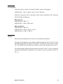
APPLDATA 004 Océ emulation 52
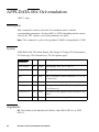
APPLDATA 005 HP emulation 55
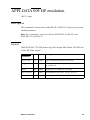
APPLDATA 006 CalComp emulation 58
APPLDATA 007 Erase disk 60
APPLDATA 008 Template and Merge 61
APPLDATA 009 User patterns 65
APPLDATA 010 Reset defaults 67
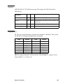
APPLDATA 011 CALS and TIFF 69
APPLDATA 012 Copy configuration 70
APPLDATA 013 Roll selection 72
APPLDATA 014 Print quality 73
APPLDATA 015 Color attributes 74
APPLDATA 020 Stamp 75
APPLDATA 021 Media selection 77
APPLDATA 022 Finishing 82
APPLDATA 023 Delivery 85
APPLDATA 024 Edge correction 88
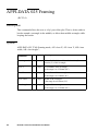
APPLDATA 025 Framing 90
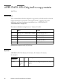
APPLDATA 026 Original to copy matrix 92
APPLDATA 027 Host requests 94
APPLDATA 028 Scan to file 96
APPLDATA 029 Image alignment 102
APPLDATA 050 HP-GL emulation 104
APPLDATA 051 HP-GL/2 emulation 107
APPLDATA 052 CALS emulation 110
APPLDATA 053 BGL emulation 111
APPLDATA 054 VDF emulation 114
APPLDATA 055 TIFF emulation 117
APPLDATA 056 ASCII 118
APPLDATA 057 PostScript emulation 120
APPLDATA 058 CalComp emulation 121
APPLDATA 059 Automatic language sensing 124
APPLDATA 060 C4 emulation 126
APPLDATA 061 NIRS emulation 127
APPLDATA 062 HP-RTL emulation 128
Backchannel messages 129
Backchannel request 129
Returned files 130
Implementation of accounting parameters 130
APPLDATA 100 Machine configuration 131
4
Remote Control Format Reference Manual
APPLDATA 101 Paper information 134
APPLDATA 102 Status information 136
APPLDATA 103 Accounting information 138
APPLDATA 104 Plot status report 143
APPLDATA 105 Controller configuration 144
APPLDATA 106 Scanner info/data 146
APPLDATA 107 Job accounting information 149
APPLDATA 108 Stamping information 152
APPLDATA 199 End of backchannel 154
Appendix A
Glossary
Appendix B
RCF grammar
Conventions 162
Grammar 163
String types 164
Metafile descriptor string 165
Command argument 166
Comments 166
Appendix C
Grouping commands and settings
System-wide commands 168
Session commands 168
Session parameters 168
Plot parameters 169
Status information 170
Appendix D
Scan to file protocol
Basic structure 172
From host to controller 172
From controller to host 172
A typical scan-to-file session 173
Multiple scans in progress 174
The SCSI connection between host and controller 175
5
A sample of interactive scan to file 176
Appendix E
Troubleshooting
Error handling 184
Invalid header 184
Invalid syntax 184
Unknown or unsupported APPLDATAs 184
Unknown or unsupported parameter 184
Out of range values 184
Unbalanced set-starts and set-ends 185
Invalid matrix program reference 185
Error reporting 186
Implementation - as per firmware types 186
Appendix F
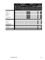
Compatibility table
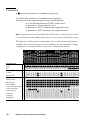
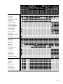
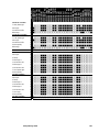
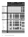
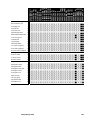
Comments 188
Appendix G
Miscellaneous
Notation conventions 200
Reader’s comment sheet 201
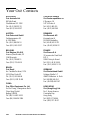
Appendix H
Océ Offices
Your Océ Contacts 204
6
Remote Control Format Reference Manual
Remote Control Format
Reference Manual
Chapter 1
Introduction
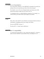
The purpose of this manual is to describe the way remote
control is supported by Océ printers. Remote control is
implemented as a file/job header, which contains
commands and parameters related to the plot itself (for
example: pen definitions, scale factor, etc.) and to the plot
management (for example: number of copies, paper size,
media saver, etc).
7
Structure of the manual
This manual is divided into ten chapters, which are summarized below. New
users are strongly advised to read Chapter 1.
Chapter 1
Introduction Organization and conventions used in this
manual. Description of the features and architecture of the
configuration files.
Chapter 2
Session management Explains the session and context
mechanism of the configuration files and job types.
Chapter 3
Remote commands A description of the application data
commands, used in the files for remote control and
backchannel commands.
Appendix A
Glossary Definitions of words, abbreviations and acronyms
used in the manual.
Appendix B
RCF grammar A description of the syntax of the remote
control format.
Appendix C
Grouping commands and settings defines the available
commands and their parameters according to whether they
apply to the following plot only or to several plots or to all
sessions.
Appendix D
Scan to file defines the communication protocol for scan to
file. (Host to/from controller).
Appendix E
Troubleshooting defines the controller’s reaction, whenever
an error occurs.
Appendix F
Compatibility A summary of the commands and parameters
supported by each printer.
Appendix G
Miscellaneous covers notation conventions and a Reader’s
comment sheet.
8
Appendix H
Océ offices gives the official list of Océ offices, Worldwide.
Index
A general quick reference section.
Remote Control Format Reference Manual
Remote configuration file structure
Your Océ plotter/printer can be configured and operated through remote
control. This is carried out by downloading configuration files which contain
all the plot parameters that must be defined according to your work
environment.
Some parameters (such as replot) may only be set from the control panel while
others may only be set from the configuration file. For detailed information on
the plot parameters that you can define for your plotter model, please refer to
your printer’s specific User's manual.
The Océ remote configuration file is made up of statements using the Clear
Text Encoding specification of the ISO Computer Graphics Metafile (CGM)
standard. Specifically, it appears as Application Data elements defined
according to the CGM standard.
This section describes the conventions for both Computer Graphics Metafile
and CGM Clear Text Application Data formats that you should follow when
making up an Océ remote configuration file.
Introduction
9
CGM metafile structure
The basic structure of the Océ remote configuration file conforms to the
following CGM specification:
BEGMF “title”;
MFVERSION 1;
MFDESC “Oce RCF, Version=2.x, Type=<type>, Unit=<unit>”;
<Oce application data>
ENDMF;
Note: RCF version 1 files use the following metafile description:
BEGMF “title”;
MFVERSION 1;
MFDESC “Oce Graphics Configuration format V1.00”;
<Oce application data>
ENDMF;
The keywords BEGMF, MFVERSION and ENDMF are required in any
CGM, and have the following meaning:
BEGMF
“;”
Begin metafile, flags the start of the configuration file and
allows the creator (the user or the application) to identify the
file with a quoted character string parameter. The length of the
string should be less than 127 characters.
The semi-colon is used as command delimiter.
MFVERSION Metafile version specifies the CGM version (currently 1).
Metafile description, is a string parameter used by Océ to
MFDESC
identify the version number of our remote control format, as
well as the type of remote configuration header (RCH). This
string is case-insensitive.
must be”2.x” for remote control headers conforming to RCF
Version
version 2. An RCH may contain version 2.x in the header, but
use commands that are introduced in RCF2.y, where y>x.
The older version 1 remote control headers use the MFDESC
line described on the previous page.
10
Remote Control Format Reference Manual
Type
Unit
is either “Header”, “MatrixPrg”, “ScanToFile”,
“StatusRequest” or “StatusInfo”.
StatusInfo is used for backchannel messages. StatusRequest is
only allowed for some particular commands, all other
commands using StatusRequest result in an error.
is either “Metric” or “Inches”. This defines how pen widths,
margins, etc. are defined.
Note: The units type inches is available only on the 9800. Océ
service may have configured the machine to work in inches or
with the metric system. The remote control values must be sent
in the units the machine is currently using.
<Oce application data> a number of lines containing the parameters. See next
section.
End metafile specifies the end of the CGM data. It must be
ENDMF
terminated by a semi-colon.
Note: Any following line break is part of the plot data. This is especially
important when the following plot is an ASCII file.
Introduction
11
Application Data structure
The CGM clear text application data format is defined as follows:
APPLDATA <command number> <data record> <terminator>
These fields must be separated by one or more of the following white space
characters:
space, hor tab, vert tab, carriage return, line feed, form feed
APPLDATA requires an integer and a string as its arguments
Command number is an ASCII digit string, representing an integer number
which identifies the command. It is limited to 3 digits, and "003", "03", and "3"
are all equivalent.
Command argument This is a single- or double-quoted string, containing a list
of parameters for the requested command (see below).
Terminator The terminator separates the different appldata elements. It is
either a semi-colon (";") or a slash ("/").
Note: The semi colon is recommended.
12
Remote Control Format Reference Manual
Command arguments
As mentioned above, the command argument (data-record) is a quoted string
which specifies the parameters. It contains a (possibly zero-length) sequence
of "key=value" pairs, separated by a comma. A white space is allowed both
before and after the comma, the string is limited to 3000 bytes.
The key is a case-insensitive string of exactly two characters of which the first
must be alphabetic, and the second alphanumeric.
(That is: [a-zA-Z][a-zA-Z0-9]).
The value may be an integer, a fixed-point number, a string or a list.
Integer (num) This is an non-negative number in the range [0 to 999999999]
(that is nine 9's). This is the maximum range for the decoder. However, every
command has its proper limits. Note that you must specify an integer when so
requested, "1.0" instead of "1" results in an error!
Fixed-point (fxp) This is a non-negative number consisting of maximal 4
significant digits before, and maximum 4 digits after the decimal point (so the
allowed range is [0000.0000 to 9999.9999]). Note that "1", "1.", "1.0", and
"001.00" all indicate the same fixed point number "0001.0000".
String (str) is limited by the following comma or the trailing quote of the data
record. This means that a string cannot contain these characters! When
specifying a string, do not make it longer than specified for the parameter in
question.
List (lst) is a list of non-negative integer numbers, enclosed by a pair of angle
brackets ‘<’and ‘>’. The numbers must be separated from each other by a space
or a comma.
Metafile comments
Comments in the metafile must be embedded between "%" characters.
Everything between a pair of "%"s is skipped.
Note that this comment format belongs to the metafile, it should not be used
outside the BEGMF … ENDMF.
Introduction
13
Decoding an RCF header
Operational behaviour
The decoder starts by reading the first file (the header). It expects the format of
the file to be as described in the previous section, and it verifies the version in
the MFDESC argument string.
After that, the APPLDATA lines will be processed one by one. They are
checked both syntactically and semantically before they will be applied. If the
same parameter (or key) is encountered more than once, its last occurrence will
be used.
The processing will end when the ENDMF keyword and the following
terminator “;” (semicolon) or “/” slash have been encountered.
Note: Multiple remote configuration header (RCH) files (either RCF version 1
or RCF version 2 having the same Type) before a plot will be concatenated.
That is, they will be considered as one file. When parameters have been defined
twice or more, the last definition is valid. You are recommended not to have
multiple RCH files before a plot.
14
Remote Control Format Reference Manual
Incomplete set of parameters
If not all possible parameters of an APPLDATA command are specified, the
attributes that are not explicitly specified will be left unchanged.
For example, a pen color can be changed without specifying a pen width,
which means that the width of the pen will be left as is.
A command may have so-called mandatory parameters. For example, you
cannot define a pen width without specifying the pen number.
Units
Some of the values in RCF version 2 headers are interpreted either in inches or
in millimetres, depending on the units setting in the header.
See note in MFDESC on page 11.
The older RCF v1 format expects millimetres.
RCF v1 and v2 compatibility
A controller that supports RCF v2 may support the older RCF v1 format (or
other revisions of the RCF for that matter), but is not obliged to do so.
Introduction
15
16
Remote Control Format Reference Manual
Remote Control Format
Reference Manual
Chapter 2
Session management
The purpose of this chapter is to explain the session and context
mechanism of the configuration files and job types.
Refer also to appendix C, ‘Grouping commands and settings’ on page 167.
17
The configuration files
Session and context
The plotter uses a number of parameters when plotting the user's files. It has
defaults for all of them, which can be overruled by sending an RCF header
before the plotfile(s).
A plotter has a least two sets of default parameters.
■ The first one consists of the factory defaults (also known as FCF- factory
configuration file), they are always present and cannot be modified.
■ The second set refers to the default context (also known as user defaults or
UCF - user configuration file), which are defined on the plotter's front panel
or with the help of a special remote control header.
The factory defaults and default context files are permanently stored in the
plotter. At plotter delivery time, both files have the same settings.
The default context is stored in the plotter/printer, and is not lost during a
power-off.
Initially (at start-up), a session context (also known as CCF- current
configuration file) is created by copying the plotter's default context. Whenever
a remote control header is received, it is applied to this session context. That
is, the session context is modified due to the merge with the received RCH.
When the plot data is received, the plot is printed with this (modified) session
context. (The session context is an intermediate file that is primarily used to
apply the parameter modifications of the current remote control header to the
next plot only, without affecting either subsequent plots or the existing UCF
parameters.)
At the end of the job, the session context is reset to the user defaults as
defined at that moment, an implicit reload.
Note: All configuration parameters set from the plotter control panel take
effect immediately and are directly written into the UCF.
• However they do not effect a plot that is being processed.
• Some control panel parameters require the plotter to be switched off and on.
18
Remote Control Format Reference Manual
Temp user
As explained above, normally a job is printed using settings from the default
context. However, a user may set up a specific context to be used for a number
of plots, thereby avoiding the use of an remote control format (RCF) header for
every file. This is done with the help of the temp user feature, which means
that the session context created by a remote control header (default context +
RCH settings) is kept for future plots (that is, the final reset of the session
context does not take place).
If the leading RCH activates the temp user mode, the following jobs will all use
this context, and if a job has an RCF header, it will be merged with this
modified session context.
The session context is reloaded with the default context at the end of a job that
has an RCF header that explicitly reloads the default context or factory
context.
For a detailed description of the Reset Defaults command, please refer to
‘APPLDATA 010 Reset defaults’ on page 67.
Session management
19
Implementations - Session management
There is a fundamental difference with respect to the operational behaviour of
the different printers and controllers:
Océ G9000-C and 9500-C It has one context that is shared between the
available interfaces. If temp user is activated by a RCH on the serial interface,
a subsequent job that arrives on the parallel port will use it.
Océ 5100, 5100C, 5200, G9000-S, 9500-S and 9400 Each interface has its own
session context, independent of all the others. The sessions interact only when
one of them redefines the default context, which is subsequently loaded by the
other sessions at the end of a job.
Océ 9600 The default context can be defined with the help of the graphic user
interface (control panel), but not using an RCF header. The temp user feature
does not exist, which means that when you want to use parameters which are
different from the defaults, an RCH must be sent for every file, or a set job
must be used (see ‘Set print job’ on page 21).
Océ 9700 and 9800 The default context can be defined with the help of the
local user interface (control panel), but not using an RCF header. The temp user
feature does not exist, which means that when you want to use parameters
which are different from the defaults, an RCH must be sent for every file, or a
set job or matrix program must be used (see ‘Set print job’ on page 21 and
‘Matrix print job’ on page 24).
20
Remote Control Format Reference Manual
Job types
There are a number of different job types, ranging from a single plotfile to a
pre-programmed documentation set.
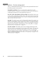
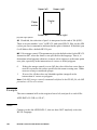
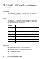
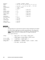
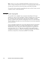
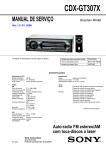
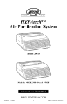
Single print job
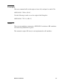
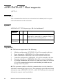
A single job is just a plot without an RCH, or with an RCH that specifies the
job type as ‘single’.
BEGMF "RCH file";
MFVERSION 1;
MFDESC “Oce RCF, Version=2.0,Type=Header, Unit=Metric”;
APPLDATA 2 "JB=0,CO=7";
APPLDATA 22 "FO=0";
ENDMF;
input:
tiff file
output:
7
6
5
4
3
2
1
PLOT file
TIFF DATA
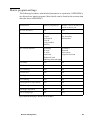
[1] Single plot file job example, 7 copies of a TIFF file unfolded.
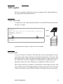
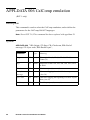
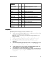
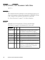
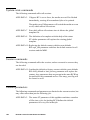
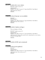
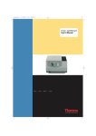
Set print job
A set job consists of a bunch of files that must be processed together because
you want to apply some treatment to all of them and specify it only once. The
most frequent use of this is no doubt making a number of copies of the whole
set of files, but it can also simplify the configuration by sending the proper
parameters only once, after which they are applied to all files in the set.
The first plot must be preceded by a special RCH, which flags the start of the
set job, and contains the default settings for all the jobs in the set. The last plot
in the set must have a special RCH to flag it as being the last plot of the job.
Session management
21
Note: An error occurs when a set-start is encountered inside a set, or when a
set-end is found without a preceding set-start.
BEGMF "RCH file";
MFVERSION 1;
MFDESC “Oce RCF, Version=2.0,Type=Header, Unit=Metric”;
APPLDATA 2 "JB=1,CO=4,CM=1";
APPLDATA 22 "FO=1";
ENDMF;
input:
3 TIFF
2 HP-GL
1 TIFF
PLOT file 1
TIFF DATA
output:
PLOT file 2
HP-GL DATA
3
3
2
2
1
1
PLOT file 3
3
3
TIFF DATA
2
2
1
1
BEGMF "RCH file";
MFVERSION 1;
MFDESC “Oce RCF, Version=2.0,Type=Header, Unit=Metric”;
APPLDATA 2 "JB=2;
ENDMF;
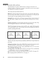
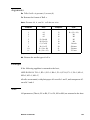
[2] Set job example, 4 sets of three files folded.
This example shows how a series of plot files need two RCHs to be printed as
a set.
The first RCH marks the start of the job (APPLDATA 2 "JB=1") and defines
the job settings. It defines how many copies (APPLDATA 2 "CO=4") are
needed and that the output must be folded (APPLDATA 22 "FO=1").
The last RCH marks the third plot file and defines the end of the job
(APPLDATA 2 "JB=2").
22
Remote Control Format Reference Manual
If required, an RCH can be added to the other files in the set which will be
applied on top of this "set context", and apply to the following plot only.
For example:
BEGMF "RCH file";
MFVERSION 1;
MFDESC “Oce RCF, Version=2.0,Type=Header, Unit=Metric”;
APPLDATA 001 "PN=001,PW=0.025";
ENDMF;
could be placed before the HP-GL file, to set pen 1 width to 0.025 mm.
When multiple copies are requested, they can be made by set (also known as
set-wise) or by page (also known as sort-wise). By set means that the copies
are made set by set (123, 123, 123,… as in the example on the previous page).
By page simply means that the copies are made plot by plot (111, 222, 333,…)
Session management
23
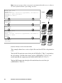
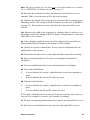
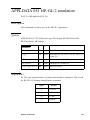
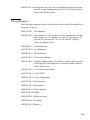
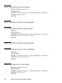
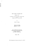
Matrix print job
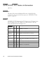
(Applies to Océ 9800) Matrix jobs allow you to create a number of different
print jobs based on the same set of files. The difference between the jobs may
be the combination of plots, the media on which they must be printed, a scale
factor, etc.
Example Imagine the following situation:
The specification of a new product must be distributed. It consists of a
specification, a parts list, and the actual mechanical and electronic design.
The distribution is as follows:
■ Marketing just wants the specification so that the product can be presented
in the catalog.
■ Supplies only needs the parts list and the specification.
■ Production wants 10 copies of the whole set on polyester.
■ Archive: needs everything on A4 sized paper. The job must be punched.
This can be printed in one cycle, by defining a program for each department.
The input looks like this:
File 1: Specification
(input size A4)
File 2: Parts list
(input size A4)
File 3: Design
(input size A2)
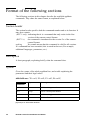
The following matrix job results in the requested output.
Parameter
Program 1
(Marketing)
Program 2
(Supplies)
#copies
Paper size
Media type
File list
Punch
1
1:1
paper
file 1
off
1
1:1
paper
file1, file2
off
[3] Matrix job example
24
Remote Control Format Reference Manual
Program 3
(Production)
Program 4
(Archive)
10
1
1:1
A4->A4, A2->A4
polyester
paper
file1, file2, file3 file1, file2, file3
off
on
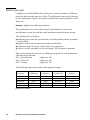
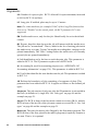
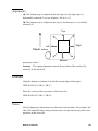
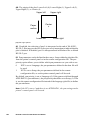
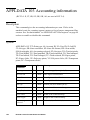
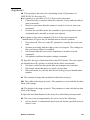
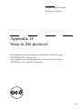
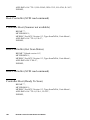
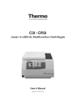
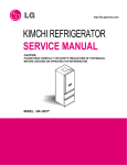
Matrix program settings
The following list shows what kind of parameters or operations (APPLDATA's)
are allowed in a matrix program. More details can be found in the sections that
describe these APPLDATA's.
APPLDATA
Matrix program file
Remote control header file
inside a matrix job
01 Pen attributes
No
Yes
02 Job parameters
(Partially)
Copies
Account Id
User Id
Copy method
Plot list
(Partially)
Job boundary
Plot number
03 Transformations
(Partially)
X scale
Y scale
Autoscale
Enhanced scale
Shift (up, down, left, right)
(Partially)
Rotation
Auto rotate
Legend correction
20 Stamp
Yes
No
21 Media Selection
Yes
No
22 Finishing
Yes
No
23 Delivery
Yes
No
24 Edge correction
Yes
No
25 Framing
Yes
No
26 Original to copy matrix
Yes
No
27 Host requests
No
Yes
29 Image alignment
Yes
No
50-59 Languages
No
Yes
[4] Commands belonging in the MP and in the RCH
Session management
25
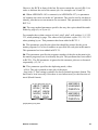
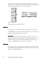
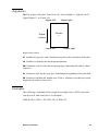
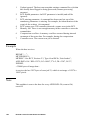
Matrix job construction
As explained on page 24, a matrix job consists of a number of small programs,
and a set of plots.
The Matrix Programs are RCF files with "type=MatrixPrg" in the header, and
they are followed by a set of plots. The RCH of the first plot should contain a
set-start, but it is optional since the first RCH that follows the last matrix
program implicitly announces the first plot. The last plot is indicated by a
set-end in its RCH.
Each matrix program contains a list, specifying which plots of the set should
be printed.
The RCH of the first plot also specifies a ‘set-context’ that will be used for all
files in the job (useful for pen settings for example). The RCH of the other plots
in the set will be applied on top of this, as described for the set-jobs, on
page 21.
Matrix
Matrix
program • • • program
1
n
RCH 1
Set
Start
Plot
1
[5] Matrix job construction
26
Remote Control Format Reference Manual
RCH
2
Plot
• • •
2
RCH m
Set
End
Plot
m
"Matrix program number 1";
MFVERSION 1;
MFDESC “Oce RCF, Version=2.0,
Type=MatrixPrg, Unit=Metric”;
APPLDATA 2 "PL=<1,2,3>,CO=2,CM=0";
APPLDATA 22 "FO=1";
ENDMF;
Input
A1
3
PLOT file 1
A0
2
PLOT file 2
A0
1
PLOT file 3
BEGMF "Matrix program number 2";
MFVERSION 1;
MFDESC “Oce RCF, Version=2.0,
Type=MatrixPrg, Unit=Metric”;
APPLDATA 2 "PL=<1,2,3>,CO=4,CM=1";
ENDMF;
BEGMF "RCH file number 1";
MFVERSION 1;
MFDESC “Oce RCF, Version=2.0,
Type=Header, Unit=Metric”;
APPLDATA 2 "JB=1, PN=1;
ENDMF;
A1
Output
A0
Plot file 1
TIFF DATA
A0
BEGMF "RCH file number 2";
MFVERSION 1;
MFDESC “Oce RCF, Version=2.0,
Type=Header, Unit=Metric”;
APPLDATA 2 "PN=2";
ENDMF;
Plot file 2
HP-GL DATA
BEGMF "RCH file number 3 ";
MFVERSION 1;
MFDESC “Oce RCF, Version=2.0,
Type=Header, Unit=Metric”;
APPLDATA 2 "JB=,PN =3";
ENDMF;
3
3
2
2
1
1
Output
A1
3
A0
2
A0
1
3
2
1
3
2
1
3
2
1
Plot file 3
TIFF DATA
[6] Matrix job example: Two matrix programs and three plot files
Session management
27
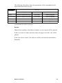
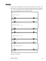
Single print jobs with overlays
The mechanism of overlays enables the user to merge several plots. An
unlimited number of files may be merged, of any kind (vector or raster) and of
any language the controller recognizes.
This feature has been added in RCF2.4.
Basic file In this document, the basic file refers to the first file which will be
put in an empty frame buffer. It determines the maximum size of the plot, the
selected paper, the paper handling functions (folding, etc.).
Overlay file An overlay file is a file that is merged with the current contents of
the frame buffer. It appears on top of the basic file and any previous overlay
files.
Overlay construction Overlay files have the same structure as basic files. They
differ through the definition of APPLDATA 8 Template/Merge.
The RCH of the basic plot must contain an ME=on(1), and all following plots
also containing ME=on(1) will be merged, up to and including the plot that has
an RCH containing ME=off(0).
RCH 1
Basic file
RCH 2
Overlay 1
RCH 3
Overlay 2
APPLDATA 8 "ME=1";
APPLDATA 8 "ME=1";
APPLDATA 8 "ME=1";
•••
RCH n
Last overlay
APPLDATA 8 "ME=0 ";
[7] Overlay construction
The basic file and overlay file are preceded by an RCH with "Type=Header" in
the header.
Settings for overlays Some of the APPLDATAs listed in this document can be
used in the Remote Control Header of the overlay file to specify:
■ the language parameters for the overlay (APPLDATAs 50, 51, 53, 54, 56, 58,
59). See page 104 to page 124.
■ scaling of the overlay and rotation relatively to the basic file (a combination
of APPLDATAs 3 and 21). See page 47 and page 77.
■ position relatively to the basic file (APPLDATAs 3 and 29). See page 102.
■ the merging method (APPLDATA 8). See page 61.
28
Remote Control Format Reference Manual
Only a few parameters among these commands are used in the RCH of overlay
files. The behaviour of these parameters, which generally differs when placed
in the overlay’s header is described within a separate paragraph for each
description.
Clipping behaviour The size of the basic plot defines the size of the final plot.
Even if the basic file’s image is smaller than the paper size, the white margin
around a drawing cannot be used for positioning overlays if it is outside the
basic image’s plot size (Bounding box).
Limitations If the basic plot is too big to fit in the Frame buffer, the merge
option will be bypassed for this plot, and the next plot will be considered as a
new basic plot if the merge option is set to on.
In the particular case where the size of an overlay plot is not known at the
beginning of the rasterization, it will be positioned at the top of the basic plot
because its height is not known (the horizontal alignment will stay the same).
Examples
This section aims to illustrate a few combinations of APPLDATAs which scale
and position an overlay relatively to a basic file.
Scale the overlay file by 141%, rotate 90 degrees relatively to the basic file and
position it in the left center of the basic file:
APPLDATA 3 “XS=1.41, YS=1.41, RO=90, AS=0, AR=0”;
APPLDATA 29 “LR=0, TB=2”;
Scale the overlay to make it fit into an A3 format:
APPLDATA 3 “AS=1”;
APPLDATA 21 “PF=3, AF=0”;
Scale the overlay down and/or rotate if necessary, so that it fits into the basic
file’s bitmap (this prevents the overlay being clipped):
APPLDATA 3 “AS=1”;
These parameters may be combined with those defined in the remote control
header of the basic file, which apply to the merged (basic + overlay) file.
Session management
29
Set print jobs with overlays
Overlays are allowed inside set jobs, but the end of a set job forces the end of
the merge set.
Matrix print jobs with overlays
A matrix job references the plots with an identification number. The use of
overlays has not been yet defined in matrix jobs.
Implementation - jobs
The Océ 9800 is currently the only machine that supports the Set jobs and
Matrix jobs features, the others only implicitly support what is referred to as
single jobs.
The overlay feature is only supported by the Océ 9700 and 9800. It is only
possible in the printing process. Overlay does not apply to copying or
scanning.
The Océ 9600 only supports Set jobs but not Matrix jobs (Release 1 firmware).
30
Remote Control Format Reference Manual
Remote Control Format
Reference Manual
Chapter 3
Remote commands
This chapter describes the commands used in the remote
configuration files:
■ What the command does
■ Which arguments it accepts and the allowed values
■ Whether or not the command is optional
■ The default values
■ Whether or not it can be stored permanently
■ If it is a command which causes an immediate action, or an
attribute to be used later on.
31
Format of the following sections
The following sections in this chapter describe the available appldata
commands. They share the same format, as explained below:
Section header
The section header specifies both the command number and as its function. It
may also contain:
(RCF 1 only) indicating that it is a command that only exists in the first
version of the remote control format.
the command is introduced in the version 2.x of the remote
(RCF 2.x)
control format.
No remark means that the command is valid for all versions.
nothing
If a command has been extended, this is noted in the text. (For example,
additional languages, parameters, etc.).
Description
A short paragraph, explaining briefly what the command does.
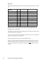
Syntax
Gives the syntax of the whole appldata line, and a table explaining the
parameters and their legal values:
APPLDATA nnn "P1=val1, P2=val2, P3=val3, P4=val4";
Type
Meaning
val1
<num>
val1 is an integer number
val2
<fxp>
val2 is a fixed-point number
val3
<str>
val3 is a string parameter
val4
<lst>
val4 is a list
parameter
[8] Example of APPLDATA attributes
32
Remote Control Format Reference Manual
Arguments
Each parameter is described in detail. If the parameter is mandatory, it is
mentioned here.
Examples
A paragraph which contains one or more examples on how the command can
be used.
Notes
Additional remarks as required.
Remote commands
33
APPLDATA 000 Print plotter config
Description
This command can be used to print the plotter's configuration, both the user's
part of it as well as the service settings. The configuration actually printed will
depend on the machine and the firmware.
Syntax
APPLDATA 000 "TY=Type, PW=Password";
Type
parameter
Meaning
Type
TY
<num> Plot configuration, either the user config (0), the
service config (1), or both (2)
Password
PW
<num> Password for the service configuration
Arguments
TY This mandatory parameter specifies what should be plotted. User
configuration refers to the user-accessible part of all settings in the session
context, which is not necessarily identical to the default context as seen on the
printer’s control panel.
A password is required in order to plot the service settings (calibration, etc.).
PW An optional parameter specifying the password for the service
configuration. Can be omitted when only the user configuration is plotted.
34
Remote Control Format Reference Manual
Examples
To plot the user configuration:
APPLDATA 000 "TY=0";
To plot both the service and the user configuration:
APPLDATA 0 "TY=2, PW=unknown";
Note
Whenever both configurations are requested but the specified password is
wrong, only the user configuration will be printed.
Remote commands
35
APPLDATA 001 Pen attributes
Description
This command is used to define the pens, their width, color, etc. for the
interpretation of vector files (BGL, HP-GL/2, CalComp, etc.). It is always
applied to HP-GL files, but for the other languages, it depends on the value of
the Pen Priority parameter (see the APPLDATA's for those languages).
Syntax
APPLDATA 001 "PN=Pen number, PW=Pen width, PP=Pen pattern, PC=Pen
color, TR=Transparency, LE=Line end, LJ=Line join, ML=Miter limit";
Type
parameter
36
Meaning
Pen number
PN
<num>
A single pen specified by a pen number, 1 to 999
<n1>-<n2> A range of pens: n1-n2, 1 <= n1 <= n2 <= 999
Pen width
PW
<fxp>
Pen width in millimetres or inches
Pen pattern
PP
<num>
Pen pattern: 1-16 are gray scales (1=white,
16=black), 17-32 are Océ patterns, 33-40 are user
defined patterns
Pen color
PC
<num>
<lst>
Pen color, black (0), hidden (2)
Pen color in RGB; <rrr ggg bbb>
Transparency
TR
<num>
Overlapping patterns are transparent (0),
or opaque (1)
Line end
LE
<num>
Butt (0), square (1), round (2), triangle (3), major
(4)
Line join
LJ
<num>
None (0), round (1), triangle (2), miter (3),
miter/bevel (4), or bevel (5)
Miter limit
ML
<fxp>
Defines the limit for the miter length/line width
ratio
Remote Control Format Reference Manual
PN Pen number is a mandatory parameter specifying either a single pen or a
range of pens to be modified.
You cannot modify pen 0, although it is a pen like all others, in HP-GL/2, for
example.
The range is specified using a hyphen ‘-’. For example, 2-45 includes pens two
to forty-five.
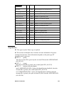
PW Pen width is an optional parameter specifying the width of the pen(s),
which will be rounded to the nearest supported number of pixels.
The supported range is machine-dependent.
The pen width may be set to 0.0 mm, which will result in a line with the
smallest width that is still visible (for example a one pixel line on the G9000
series machine).
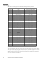
The minimum and maximum value the controllers are able to handle is defined
in the following table:
Resolution
Minimum
Maximum
Default
300
0.08mm
10.75mm
0.25mm
400
0.06mm
8.06mm
0.19mm
FA, FB, FP, FR 300
0
10.75mm
0.25mm
400
0
10.75mm
0.19mm
400
0
16.25mm
(0.639")
0.19mm
(0.007")
controller
ME
FS
[9] Maximum and minimum pen widths
RCF 1 assumes that the given widths are in mm's,
RCF 2.x interprets it according to the unit setting in the header.
Remote commands
37
PP Pen pattern is an optional parameter. 40 patterns are available of which the
+ + + ++ + + + + + + ++ + + +
+ + + ++ + + + + + + ++ + + +
first 16 (1-16) correspond to increasing shades of gray (1=white, 16=black),
the next 16 (i.e. 17-32) are Océ defined patterns and the last 8 (33-40) may be
user defined. See page 65.
17 18 19 20 21 22 23 24 25 26 27 28 29 30 31 32
[10] Océ defined pen patterns
PC Pen color is an optional parameter.
In RCF v1 and v2.0, it can be specified as either black (0) or hidden (2). Color
1 used to be red for bi-color paper, but is not available in any product.
In RCF 2.1 or later, a list is expected, containing 3 values between [0-255],
specifying the Red, Green and Blue components.
TR Transparency, an optional parameter, which can be enabled (0) or
disabled (1).
When enabled, overlapping lines and polygons shine through, the white pixels
are transparent. When disabled, only the last applied fill is visible and
completely hides the ones underneath.
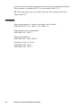
LE Type of line-end. Not all languages support all types of line-ends, as
indicated in the table:
Butt
Square
Round
HP-GL/2
•
•
•
CalComp
•
•
•
•
•
BGL/VDF
[11] Line end types supported
38
Remote Control Format Reference Manual
Triangle
Major
•
•
Regarding CalComp, ‘butt’ is known as ‘flat’ and line end type ‘major’ means
that the line-end will be horizontal if the line more closely aligns to the Y axis,
and vertical if it aligns more closely to the X axis:
Y
Closer to Y
Closer to X
X
[12] CalComp line end type "Major"
This parameter has been added in RCF 2.1.
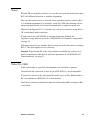
LJ Type of line-join. Not all languages support all types of line-joins, as
indicated in the table:
butt
square
round
HP-GL/2
•
•
•
CalComp
•
•
•
•
•
BGL/VDF
triangle
major
•
•
[13] Line join types supported
This parameter has been added in RCF 2.1.
Remote commands
39
ML The miter limit specifies the ratio between the miter length and the line
width.
Line width
Miter length
Miter limit =
Miter length
Line width
[14] Miter limit
This parameter has been added in RCF 2.1.
Examples
Define pens 1-10 as transparent gray, width 1 mm:
APPLDATA 1 "PN=1-10, PW=1.0, PP=4, PC=0, TR=0";
Make pen 7 invisible, leaving its width, pattern and transparency unchanged:
APPLDATA 1 "PN=7, PC=2";
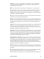
Notes
For a correct setup of pens on the 5100C, the command APPLDATA 015 color
mode must be sent before the pen attributes command APPLDATA 001.
When the same pen is redefined multiple times, the last definition applies.
Only the pen number parameter is mandatory. The others may be omitted,
leaving the corresponding pen attribute unchanged.
One APPLDATA must be sent for each different pen configuration. That is, the
following command does not work:
APPLDATA 1 "PN=1-5, PW=1.0, PC=0, PN=6, PW=1.5, PC=2";.
Instead, use the following two commands:
APPLDATA 1 "PN=1-5, PW=1.0, PC=0";
APPLDATA 1 "PN=6, PW=1.5, PC=2";.
40
Remote Control Format Reference Manual
APPLDATA 002 Job parameters
Description
This command defines the parameters of the plot file or different jobs that may
be used: single jobs, set jobs or matrix jobs.
Note: The parameters of this command may be found in the plot header (RCH)
or in the matrix program (MP).
Syntax
APPLDATA 002 "CO=Copies, LP=Long plot, EM=Efficiency manager,
BY=Bypass, JI=Job identification, AI=Account identification, UI=User
identification, JB=Job boundary, AC=Accounting, CM=Copy method,
PL=Plot list, PN=Plot number, DU=Duplex";
Type
parameter
Meaning
Copies
CO
<num> Number of copies to print, 1…999
Long plot
LP
<num> Allow long plot, up to 15 meters. Either disabled (0),
or enabled (1).
Efficiency
Manager
EM
<num> Usually referred to as media saver, either disabled (0),
or enabled (1).
Bypass
BY
<num> Plot should accumulate (0), be forced (1), or bypass
(2).
Job Id
JI
<num> A nine-digit number identifying the job.
Account Id
AI
<num> A nine-digit account number.
User Id
UI
<num> A nine-digit number user identification.
Job boundary JB
<num> Single file (0), start of set (1), end of set (2).
Accounting
AC
<num> Either enabled (1) or disabled (0).
Copy method
CM
<num> Make the copies by page (0) or by set (1).
Plot list
PL
<list>
Plot number
PN
<num> Number of the plot inside the matrix job.
Duplex
DU
<num> Duplex printing, off (0), long side (1) or short side (2).
Remote commands
List of plots for the specified matrix program.
41
Arguments
CO Number of copies to plot. RCF 1 allowed 99 copies maximum, increased
to 999 for RCF 2.0 and later.
LP Long plot. If enabled, plots may be up to 15 meters.
Note: For some machines (for example 5100C) if the Long Plot function has
been set to "Disable" at the control panel, the RCF parameter LP is not
supported.
EM Enable media saver, only for this job. Should really be set in the default
context.
BY Bypass, describes how the next the job will interact with the media saver.
The job can be "accumulated". That is, added to the list of waiting jobs inside
the media saver, or it may "bypass" the media saver altogether, causing it to be
plotted immediately. The "force" setting flushes the media saver, all currently
queued jobs are printed immediately.
JI Job identification set by the host to track the print jobs. This parameter is
added in RCF 2.4. The JI parameter replaces the old PI Plot Id.
AI Accounting Id, used for accounting purposes (see ‘APPLDATA 103
Accounting information’ on page 138). This parameter is added in RCF 2.0.
UI User Id that identifies the user that has sent the job. This parameter is added
in RCF 2.0.
JB Defines the boundaries of jobs consisting of a sequence of plots. This
parameter has been added in RCF 2.0. It applies as follows to the defined job
types:
Single job The job consists of only one plot, the JB parameter is not needed in
that case (it defaults to 0, single file). See ‘Job types’ on page 44 and the
example on page 21.
Set job The RCH in front of the first must contain a set-start (JB=0), and the
RCH in front of the last file of the job must contain a set-end (JB=1). See ‘Job
types’ on page 44 and the example on page 21.
Matrix job The start of a matrix job is flagged by the first matrix program. The
RCH in front of the first plot after the matrix program(s) implicitly contains a
set-start. That is, it is optional.
42
Remote Control Format Reference Manual
However, the RCH in front of the last file must contain the set-end (JB=1) in
order to indicate the end of the matrix job. See examples on 24 and 24.
AC When APPLDATA 103 is returned (via APPLDATA 027), its parameter
AS contains the value set in this AC parameter. This can be used by the host to
identify jobs that were not meant to be accounted. This parameter is added in
RCF 2.0.
CM The copy method parameter specifies the way the copies should be made.
Either by page (0), or by set (1).
For example the set that consists of plot1, plot2, plot3, will produce 111, 222,
333, when printing by page. The same set will produce copies 123, 123, 123
when printing by set. This parameter has been added in RCF 2.1.
PL This parameter specifies the plots that should be printed for the given
matrix program. It is a list of numbers as specified for each plot in the matrix.
This parameter has been added in RCF 2.1.
PN This parameter specifies the sequence number of the plot in the matrix job,
the matrix program(s) use it to identify the plot. This parameter has been added
in RCF2.1. The PN parameter is ignored at the moment, plots are referenced
sequentially (1,2,3,4...).
DU This parameter specifies the duplexing mode, either
- off (0) The job is printed on one side of the paper
- long side (1) This setting is suitable for sheets printed in portrait format. The
back can be read correctly if the sheet is used transversely to the direction of
travel (Book format).
ABCD
EFGH
IJKLM
NOPQ
STUV
ABCD
EFGH
IJKLM
NOPR
STUV
ABCDEFG
HIJKLMNO
PQRSTUV
ABCDEFG
HIJKLMNO
PQRSTUV
[15] Duplexing long side
Remote commands
43
- short side (2). The back can be read correctly if the sheet is used in the
direction of travel of the paper (Calendar format). This setting is suitable if four
A4 pages are to be printed on one A3 sheet, for instance.
ABCD
EFGH
IJKLM
NOPQ
RSTU
ABCD
EFGH
IJKLM
NOPQ
RSTU
ABCDEF
GHIJKLM
NOPQRS
ABCDEF
GHIJKLM
NOPQRS
[16] Duplexing short side
This parameter has been added in RCF2.5.
Notes
The ‘Bypass=force’ option does not flush the job that follows the RCH.
If the APPLDATA is specified in the MP or RCH where it is not allowed, it is
ignored and a job description error is generated.
Caution: Both the accumulate and the bypass settings are actually job
attributes, while the force plot is more like a command. However, the force
setting is stored in the context and may even be stored in the user
configuration file, so be careful when combining this with the temp user
mode (see ‘APPLDATA 010 Reset defaults’ on page 67).
Job types
This section describes specific job-types, as defined in the metafile description,
(see MFDESC on page 10) and their related limitations. See ‘Job types’ on
page 21 for additional information.
44
Remote Control Format Reference Manual
The following table shows where the parameters of this command must be
used in function of the job type.
Job Type
Parameter
Single
Set
Matrix
Copies
Remote configuration header
Set header
Matrix program
Copy method
Remote configuration header
Set header
Matrix program
Plot list
-
-
Matrix program
Plot number
-
-
Remote configuration header
[17] Parameters as a function of job type
Set jobs
Manual sheet printing is not allowed within a set, the request will be ignored.
If there is a time-out (that is,no more data), the pages received so far will be
printed.
If the user selects 'cancel', the whole set will be read until its end and then
discarded.
Remote commands
45
Matrix jobs
The following table explains where the commands must be placed in a matrix
job:
Appldata
Pen attributes
01
Job parameters
02
Transformations
03
Stamp
20
Media selection
21
Finishing
22
Delivery
23
Edge correction
24
Framing
25
Original to Copy matrix 26
Host requests
27
Image alignment
29
Languages
50-59
Matrix program
Remote control header
No
Yes
Partially
Yes
Yes
Yes
Yes
Yes
Yes
Yes
No
Yes
No
Yes
Yes
Partially
No
No
No
No
No
No
No
Yes
No
Yes
Bypass cannot be used in matrix jobs; if present, it is ignored and a job
description error is generated.
The number of matrix programs is limited to 40, any others are ignored and a
job description error is generated.
There can be up to 40 different reductions (scale factors), one for each matrix
program. (Enlargement is not possible).
One matrix job cannot use more than four different rolls.
If there is a different print orientation (due to (auto)rotation) for one plot in
different matrix programs, the controller reports a job description error and
generates the bitmap according to the settings of the first referenced matrix
program.
46
Remote Control Format Reference Manual
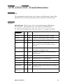
APPLDATA 003 Transformations
Description
This command is used to rotate, scale, mirror, or shift the plot. Some of the
parameters are also used to position overlays relatively to the basic plot.
Syntax
APPLDATA 003 "XS=X scale, YS=Y scale, RO=Rotation, MR=Mirror,
AS=Autoscale, ES=Enhanced scale, SU=Shift up, SD=Shift down,
SL=Shift left, SR=Shift right, AR=Auto rotate, LC=Legend correction"
parameter
Type
Meaning
X Scale
XS
<fxp>
X scale (or zoom) factor, 0.0500 - 20.0000
Y Scale
YS
<fxp>
Y scale (or zoom) factor, 0.0500 - 20.0000
Rotation
RO
<num> Rotation angle, 0, 90, 180, or 270 degrees
Mirror
MI
<num> Either no mirror (0), mirror on the X axis (1), or
mirror on the Y axis (2). Also known as plot
symmetry
Auto scale
AS
<num> Either disabled (0), to-format (1), or best-fit (2).
Also known as automatic zoom.
Enhanced scale ES
<num> Disabled (0) or Enabled (1). Also referred to as
enhanced zoom.
Shift Up
SU
<fxp>
Upward shift, 0 to 1219mm (48")
Shift Down
SD
<fxp>
Downward shift, 0 to 1219mm (48")
Shift Left
SL
<fxp>
Left shift, 0 to 914mm (36")
Shift Right
SR
<fxp>
Right shift, 0 to 914mm (36")
Auto Rotate
AR
<num> Automatic rotation, either disabled (0), folding (1),
or productive (2)
Legend
correction
LC
<num> Title block positioning, disabled (0) or enabled (1)
Remote commands
47
Arguments
XS This is the scale factor along the X axis of the drawing. The allowed range
is from 0.0500 to 20.0000 for RCF 1. For RCF 2, see the printer User’s
documentation for details.
Overlays This is the scale factor along the X axis of the overlay file relative to
the basic fileS.
YS This is the scale factor along the Y axis of the drawing. The allowed range
is from 0.0500 to 20.0000 for RCF 1. For RCF 2, see the printer User’s
documentation for details.
Overlays This is the scale factor along the Y axis of the overlay file relative to
the basic file.
RO The angle over which the drawing is rotated (counter-clockwise), either no
rotation (0 degrees), 90, 180, or 270 degrees. This rotates the whole drawing
(including the axis) around the origin, it does not affect X scale or Y scale.
Overlays
Rotates the overlay (by 0, 90, 180, or 270 degrees) relative to the
basic file.
MR Whether or not the drawing is mirrored, and if so, in the X or the Y axis
of the drawing. Note that mirror function does not shift the drawing, which
may be partially clipped when mirror is selected.
Overlays
The mirror option is ignored for overlay files.
AS Auto scale (also known as automatic zoom):
1
Scale to format selects an automatic scaling factor, as a function of the
paper format and the plot size (Bounding box). The paper format can be
specified using ‘APPLDATA 021 Media selection’ on page 77.
2
Best-fit means that a plot bigger than the available paper (as mounted on
the machine) will be scaled down and/or rotated to make it fit. This
allows plots not to be clipped. (Not supported by Océ 9700 and 9800
printers).
The auto scale parameter is added in RCF 2.0. The best-fit option has been
introduced in RCF 2.2.
Overlays Scale to format selects an automatic scaling factor, as a function of
the overlay’s size (Bounding box) and the paper format that can be specified in
the header of the overlay using ‘APPLDATA 021 Media selection’ on page 77.
48
Remote Control Format Reference Manual
The best-fit scaler option is ignored for overlay files.
ES Enhanced-scale (also known as enhanced-zoom) controls the scaling of the
pen width.
0
1
If disabled, the full image is scaled, including the vector lines.
If enabled, the width of the vector lines doesn't change, whatever the
zoom factor.
This parameter is added in RCF 2.0.
Overlays Same as basic file.
SU Upward shift along the paper feed axis. May be given in mm or in inches,
depending on the selected unit setting in the header. This parameter is added in
RCF 2.0.
SD Downward shift along the feed axis of the paper, in mm or in inches. This
parameter is added in RCF 2.0.
SL Leftward shift along the cross-feed axis. May be given in mm or in inches,
depending on the selected unit system. This parameter is added in RCF 2.0.
SR Rightward shift along the cross-feed axis, in mm or in inches. This
parameter is added in RCF 2.0.
Overlays Shifts the overlay bitmap relatively to the basic file. Done after the
rotation RO and alignment (APPLDATA 29 LR and TB) functions.
Note: If both shift up and shift down are given, the last one is used. The same
applies for shift left and shift right.
Unfolded output tray
up
Paper
motion
right
left
down
[18] Shift directions
Remote commands
49
AR Auto rotation:
1
2
Folding, the drawings will be automatically rotated 90°, if needed, in
order to have the legend (title block) on top after folding (which depends
on the folding method used).
Productive, the drawings will be printed in landscape when possible, in
order to achieve the highest productivity. If the landscape format is not
available, the portrait format is used instead (For example, an A1 will be
printed using the A1-roll instead of the A0-roll that would be needed for
the landscape format). If auto rotation is enabled, the rotate parameter is
ignored. This parameter is added in RCF 2.0.
Ignored for overlay files.
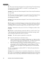
LC If title block position (legend correction) is enabled, it will cause the plot
to be rotated 180 ° on the paper. This is independent of the Rotate parameter.
Paper
motion
[19] Title block position (Legend correction)
When a plot must be folded, the machine is able to print it in portrait, but it
doesn’t know whether the drawing is upside-down or not. Since that depends
on the printer driver (and possibly also on the application), the LC setting
should be set to make sure the title block is located in the correct corner. (This
need be done only once, if the drawings are always generated with the same
application and driver).
The LC setting is added in RCF 2.2, and only active when the Auto Rotate
parameter is set to productive or folding.
Overlays Ignored for overlay files.
50
Remote Control Format Reference Manual
Examples
Scale the plot by a factor 2 in both X and Y, rotate it 90 degrees:
APPLDATA 3 "AS=0, AR=0, XS=2, YS=2, RO=90";
Scale the overlay by 200 % and place in the center of the basic file, rotate the
whole bitmap 180 degrees:
RCF basic file
APPLDATA 8 "ME="1";
APPLDATA 3 "AR=0, RO=180";
RCF overlay file
APPLDATA 8 "ME=0";
APPLDATA 3 "AS=0, XS=2, YS=2";
APPLDATA 29 "LR=2, TB=2";
Notes
Maximum and minimum scale factors are machine dependent.
If autoscale AS and auto rotate AR are enabled, parameters X scale XS, Y scale
YS and Rotation RO are ignored. Therefore, in order to scale or rotate using
XS, YS and RO, the autoscale AS and auto rotate AR must both be set to 0.
To avoid possible conflict between autoscale and X scale/ Y scale, in printers
which use the FRISCO controller, if you want to use X scale and Y scale, set
AS = 0.
Remote commands
51
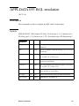
APPLDATA 004 Océ emulation
(RCF 1 only)
Description
This command is used to select the Océ emulation mode, with the
corresponding parameters. It selects BGL or VDF (depending on the current
value of the ‘DF’ option), even if no parameters are given.
Note: This command is replaced by appldata53 (BGL) and appldata54 (VDF).
Syntax
APPLDATA 004 "DF=Data format, OR=Origin, ST=Step, FN=Font number,
FT=Font type, CH=Character set, TY=Océ plotter type";
Type
parameter
Meaning
Data Format
DF
<num> Plot language, BGL (0) or VDF (1)
Origin
OR
<num> Plot origin, LL (0), LR (1), UL (2), UR (3), Center
(4)
Step
ST
<fxp>
Font Number
FN
<num> Font number, either primary (1), or secondary (2)
Font Type
FT
<num> Font type, Isoarc (0), Din17 (1), Leroy (2), Cyrillic
(3), or Isovec (4)
Character Set
CS
<num> Character set, only applies to Isoarc and Isovec (see
below)
Océ plotter type TY
<str>
Unit of coordinate system in microns, 12.5, 25, 50,
or 100 micron
Plotter identification string (10 chars maximum).
Arguments
DF The format of the data that will follow, either BGL (DF=0), or VDF
(DF=1).
52
Remote Control Format Reference Manual
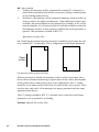
OR The origin of the plot, Lower-Left (0), Lower-Right (1), Upper-Left (2),
Upper-Right (3), or Center (4).
Upper left
Paper
motion
Upper right
Center
Lower left
Lower right
[20] Océ plot origin
ST Step Size, the unit for the coordinate system in microns, either 12.5, 25, 50,
or 100 microns.
FN Font number, either the primary (1), or the secondary (2) font. This
parameter is mandatory in the sense that whenever font type FT and/or
character set CH are present, you must specify the font to modify.
FT Font type for the specified font: DIN17, LEROY, CYRILLIC, ISOARC or
ISOVEC.
CH Character set. Only applies to the ISOARC and ISOVEC fonts, for which
the following character sets are available:
■ ISOARC: 20, 25, 29, 50 to 59, and 80
■ ISOVEC: 0, 5, 9, 30 to 39, and 60
If you specify this parameter, you must specify font number FN and font type
FT as well.
TY Plotter identification string, 10 characters maximum. This string is
returned when BGL's IC-11 (Inquire device identification, 0x2B in VDF) or RI
(Return Identification, 0x28 in VDF) command is received.
Remote commands
53
Examples
The following command states that the input language will be BGL, step size
50 micron, origin in lower-left corner, and primary font set to LEROY:
APPLDATA 4 "DF=0, OR=0, ST=50, FN=1, FT=2";
Notes
This command has to be used twice in order to define both fonts, i.e.
APPLDATA 4 "FN=1, FT=0, CH=20, FN=2, FT=4, CH=5";
does not work.
Instead, use the following two commands:
APPLDATA 4 "FN=1, FT=0, CH=20";
APPLDATA 4 "FN=2, FT=4, CH=5";
There are no mandatory parameters, APPLDATA 4 switches to Océ emulation
even when no parameters are given.
54
Remote Control Format Reference Manual
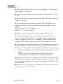
APPLDATA 005 HP emulation
(RCF 1 only)
Description
This command is used to select either HP-GL or HP-GL/2, and to specify some
related parameters.
Note: This command is replaced with the APPLDATA 50 (HP-GL) and
APPLDATA 51 (HP-GL/2).
Syntax
APPLDATA 005 "TY=HP plotter type, OR=Origin, MO=Mode, SP=SP0 end
of file, DF=Data format";
Type
parameter
Meaning
Plotter type
TY
<num> Type of emulated HP plotter, see below.
Origin
OR
<num> Plot origin, LL (0), LR (1), UL (2), UR (3), Center
(4), or Auto (5)
Mode
MO
<num> Emulate (0), or normal (1), see below.
SP0 end of file SP
Data format
DF
Remote commands
<num> Pen 0 indicates end of file, yes (0), or no (1).
<num> Plot language, HP-GL (0) or HP-GL/2 (1).
55
Arguments
TY The type (model number) of plotter that should be emulated. This is used
for HP-GL's OI (Output Identification) command, and for the automatic origin
mode (see below).
Type
Model
Automatic
origin
Type
Model
Automatic
origin
0
1
2
3
4
5
HP-7440
HP-7475A
HP-7550A
HP-7570A
HP-7580A
HP-7580B
Lower right
Lower right
Lower right
Center
Center
Center
6
7
8
9
10
11
HP-7585B
HP-7586B
HP-7595A
HP-7596A
HP-7600
DesignJet
Center
Center
Center
Center
Lower right
Lower left
[21] HP plotter types
OR The origin of the plot, Lower Left (0), Lower Right (1), Upper Left (2),
Upper Right (3), Center (4), or Auto (5). In auto-mode, the origin is derived
from the default origin of the emulated plotter.
MO Emulation mode. If set, the following HP-GL instructions are modified to
be compatible with the HP-9872 plotter:
DF
Set to Defaults
DR
Direction relative
IN
Initialise plotter
IW
Input window
OC
Output commanded pen status
OD
Output Digitised point and pen status
OP
Output P1 and P2 points
SI
absolute character size
SR
Relative character Size
UC
User defined Character
SP If enabled, the selection of pen 0 is interpreted as the end of file EOF. There
is no pen#0 in HP-GL, and some HP-GL files use the SP0 command to indicate
that the plot is finished. If disabled, pen0 is interpreted as a 2 or 3 pixels wide
pen. (Depending on the plotter used).
Note: HP-GL/2 is able to use pen 0 as any other pen.
DF Data format, either HP-GL (0) or HP-GL/2 (1).
56
Remote Control Format Reference Manual
Examples
The next command will set the origin to lower left, and pen 0 as end of file:
APPLDATA 5 "OR=0, SP=0";
Use the following in order to use the origin of the DesignJet:
APPLDATA 5 "TY=11, OR=5";
Notes
There are no mandatory parameters, APPLDATA5 switches to HP emulation
even when no parameters are given.
The automatic origin (OR=auto) is not implemented on all machines.
Remote commands
57
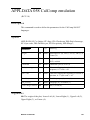
APPLDATA 006 CalComp emulation
(RCF 1 only)
Description
This command is used to select the CalComp emulation, and to define the
parameters for the CalComp 906/907 languages.
Note: Since RCF 2.0, This command has been replaced with appldata 58.
Syntax
APPLDATA 006 "OR=Origin, ST=Step, CK=Checksum, EM=End of
message, SY=Sync code, DB=Double sync";
Type
parameter
58
Meaning
Origin
OR
<num> Plot origin, LL (0), LR (1), UL (2), UR (3), or
Center (4)
Step
ST
<num> Steps/inch. Either 100, 200, 400, 500, 1016, 2032,
or 4064
Checksum
CK
<num> Checksum yes (0), or no (1)
End of
message
EM
<num> Character flagging the end of the data sequence,
(0 to 30)
Sync code
SY
<num> Character flagging the beginning of a block of plot
data, (0 to 63)
Double sync
DB
<num> Double sync yes (0), or no (1)
Remote Control Format Reference Manual
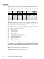
Arguments
OR The origin of the plot, Lower-Left (0), Lower-Right (1), Upper-Left (2),
Upper-Right (3), or Center (4).
Upper left
Paper
motion
Upper right
Center
Lower left
Lower right
[22] Plot origin options
ST Number of steps per inch, should correspond to the resolution of the plot.
CK Enables or disables the checksum mechanism.
EM Character code for the end-of-message byte, indicating the end of a data
sequence.
SY Character code for the sync byte, indicating the beginning of the plot data.
DB Enables or disables the double sync. That is, whether or not the byte which
begins the plot data is sent twice.
Examples
The following command will set origin lower-right, step to 2032 steps/inch,
sync byte to 0, and eom byte to 30 (decimal):
APPLDATA 6 "OR=1, ST=2032, SY=0, EM=30";
Remote commands
59
APPLDATA 007 Erase disk
Description
This command erases all plot data from the plotter's internal hard disk, both
plot file(s) and template(s). The user defaults and factory defaults are
preserved.
This command is also known as "Data Security".
Syntax
APPLDATA 007 "";
Arguments
None.
Examples
The next command will erase all information on the plotter's internal hard disk
APPLDATA 7 "";
60
Remote Control Format Reference Manual
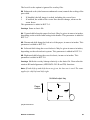
APPLDATA 008 Template and Merge
(RCF 1.0. ME was added in RCF 2.0, MM was added in RCF 2.4)
Description
This command controls the creation and use of template files and the merging
of plots. A template is a file that is stored in the plotter for future reference,
while merging actually overlays consecutive files.
There is currently only support for one template.
Syntax
APPLDATA 008 "ST=Status, ME=Merge, MM=Merge method";
Type
parameter
Meaning
Status
ST
<num> Template disabled (0), enabled (1), or define (3)
Merge
ME
<num> Merge mode off (0) or on (1)
Merge method MM <num> Overlay (0), Or (1), Exclusive Or (2), And (3)
Arguments
ST This single parameter controls both the usage, as well as the definition of
a template.
When the template is enabled (ST=1), the following plot (either vector or
raster) will be merged with the template as stored inside the machine. Nothing
happens if no template has been defined.
When ST is set to 3, the following plot will be stored as a template, the "erase
disk" APPLDATA 07 can be used to remove it.
ME This setting determines if the following plots will be merged. The RCH of
the basic plot to be merged must contain an ME=on (1), and all following plots
will be merged, up to and including the plot that has an RCH containing
ME=off (0). Default value for ME is off (0).
Remote commands
61
MM The way an overlay is merged with the basic plot (or the result of the
preceding mergings). It may take one of the following values:
0
1
2
3
Overlay. Black or white pixels of the second plot replace those of the
previous one. This is also called copy.
Or. Both plots are merged. Any black pixels in either the first plot or the
second plot are printed.
XOR. An exclusive OR is made. Any black pixels in the first plot which
coincide with pixels in the second plot are turned white. This allows
reverse images (negatives) of plots.
And. Logical AND. Only pixels which are black in the first plot and
which coincide with black pixels in the second plot are printed.
The following drawing summarizes the above description for each method.
Plot A represents the basic plot (or the results of the preceding mergings) while
plot B is the overlay (for which parameter MM is defined).
Plot A
Overlay
Merge (OR)
Exclusive OR
AND
[23] Merge and overlay
Default value is OR.
This parameter is added in RCF 2.4.
62
Remote Control Format Reference Manual
Plot B
Result
Examples
(1) Plot 2, plot 3 and plot 4 will be merged with the HP-GL file of plot 1. The
BGL file plot 2 will first be merged using the or method, then the CalComp file
plot 3 will be merged with the xor method and finally the CALS file plot 2 is
copied (overlayed) (MM=0) onto the whole bitmap:
BEGMF "RCH file";
…
% Merge ON %
APPLDATA 8"ME=1";
…
ENDMF;
PLOT file 1
HP-GL DATA
BEGMF "RCH file";
…
% Overlay file%
APPLDATA 8"ME=1, MM=1";
…
ENDMF;
PLOT file 2
BGL DATA
BEGMF "RCH file";
…
% Overlay file%
APPLDATA 8"ME=1, MM=2";
…
ENDMF;
PLOT file 3
CalComp DATA
BEGMF "RCH file";
…
% Last overlay file%
APPLDATA 8"ME=0, MM=0";
…
ENDMF;
PLOT file 4
CALS DATA
[24] Example of merged files
Remote commands
63
(2) Store next plot as template:
APPLDATA 8 "ST=3";
Merge next plot with template:
APPLDATA 8 "ST=1";
Notes
Only vector files can be used as templates. Scaling and rotation are applied
before the template is stored.
Merging can be done with any type of plot. That is, raster and vector plots can
be merged.
The size of a merged plot is determined by the basic plot. If a following plot is
larger, it is clipped.
The merge method MM parameter is ignored for basic files.
The status parameter (ST) is ignored when the merge parameter (ME) is set to
on (1).
64
Remote Control Format Reference Manual
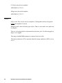
APPLDATA 009 User patterns
(RCF 1 only)
Description
This command is used to define the eight available user patterns.
Syntax
APPLDATA 009 "ID=Index, PA=Pattern";
Type
parameter
Meaning
Index
ID
<num> Number of the user pattern that is about to be
defined (1 to 8)
Pattern
PA
<num> A sequence of 1024 0's and 1's, defining a 32x32
monochrome pattern.
Arguments
ID The number of the user pattern that is going to be defined. Note that user
patterns 1 to 8 are selected as pen pattern 33 to 40.
PA A sequence of exactly 1024 pixel data elements, each with a value of 1 or
0, defining a 32x32 bit pattern, the digits all separated from each other by white
space (That is, one or more occurrences of htab, space, cr, lf, vtab, and/or
formfeed).
Examples
The following command defines user pattern 3:
APPLDATA 9 "ID=3, PA=
11110000111100001111000011110000
11110000111100001111000011110000
11110000111100001111000011110000
11110000111100001111000011110000
Remote commands
65
00001111000011110000111100001111
00001111000011110000111100001111
00001111000011110000111100001111
00001111000011110000111100001111
…< 16lines left out >…
11110000111100001111000011110000
11110000111100001111000011110000
11110000111100001111000011110000
11110000111100001111000011110000
00001111000011110000111100001111
00001111000011110000111100001111
00001111000011110000111100001111
0 0 0 0 1 1 1 1 0 0 0 0 1 1 1 1 0 0 0 0 1 1 1 1 0 0 0 0 1 1 1 1";
Notes
A number of bits less than or greater than 1024, or digits other than 0 and 1 are
considered to be an error, causing the pattern definition to be rejected.
The only machines that support this appldata are the Océ G9000-C and
Océþ9500-C series (ME 2.x).
66
Remote Control Format Reference Manual
APPLDATA 010 Reset defaults
Description
This command manipulates the machine's contexts.
Syntax
APPLDATA 010 "RD=Reset defaults";
parameter
Reset defaults RD
Type
Meaning
<num> Load factory defaults (0), load default context (1),
replace default context (2), or temp user (3)
Arguments
RD The load factory and load user commands can be used to reinitialise the
current context, it will be replaced by the factory defaults (RD=0), or the
default context (RD=1) respectively.
The factory defaults are always present and cannot be modified. However, the
user can create a custom setup by defining a so-called default context. This is
done by sending an RCH and storing the resulting context as the default
context by setting RD=2.
By default, each job starts with a context equal to the user defaults, since this
context has been restored automatically at the end of the previous job. The
temp user setting can be used to disable this mechanism, causing the context
to remain in effect for multiple jobs, until a new RCH is received with an RD
other than 3. The temp user flag is not reset automatically, it is by default off.
Examples
The next command will activate the "temp user" feature. That is, the current set
of attributes/parameters will remain active until another RCH is received:
APPLDATA 10 "RD=3";
Remote commands
67
Notes
The "load default" and "replace default" commands are executed immediately,
so any preceding settings are lost on the "load default context", while following
APPLDATA commands will not be part of the new default context on a
"replace default context" command.
The temp user feature must be disabled explicitly by sending an RCH
containing an RD other than 3.
The temp user should really be a job-attribute, while the others (load factory
defaults, load default context and replace default context) are actions.
68
Remote Control Format Reference Manual
APPLDATA 011 CALS and TIFF
(RCF 1 only)
Description
This command indicates that the following plot data should be treated as a
CALS or TIFF file.
Note: This command has been replaced by the APPLDATA 52 (CALS) and
APPLDATA 55 (TIFF).
Syntax
APPLDATA 011 "SC=Scale";
Type
parameter
Scale
SC
Meaning
<num> Convert (0), autoscale (1), autoscale if clipped (2)
Arguments
SC This parameter controls the scaling of the image. SC=0 means that a
resolution conversion takes place. That is, the image is scaled to its proper size
with respect to the source resolution.
Setting SC=1 will always scale the image to the paper size.
SC=2 will only scale the image to the papersize in case it would be clipped.
Note: The controller may autorotate the rasterfile before it autoscales.
Autorotate is always on, and takes place when the image's width is larger than
its height and its width exceeds the width of the printable area.
Example
This command switches to CALS/TIFF interpretation and enables autoscale:
APPLDATA 11 "SC=1";
Remote commands
69
APPLDATA 012 Copy configuration
(RCF 2.0)
Description
This command specifies how the controller should handle the number of
copies requested in the RCF header and in the plot file.
Syntax
APPLDATA 012 "CC=Copy configuration";
Type
parameter
Copy config
CC
Meaning
<num> Ignore copies in plotfile (0), maximum of context or
plotfile (1), context x plotfile (2), ignore context (3)
Arguments
CC The number of copies as specified in the plotfile:
0
The number of copies as specified in the plotfile is ignored. Only the
number of copies requested in the context ( RCF header) is taken into
account. Refer to See ‘Session and context’ on page 18 for further
explanation.
1
The number of copies is the maximum of the context (RCF header) or the
plotfile.
2
The total number of copies printed is the number of copies specified in
the context (RCF header) multiplied by the number of copies as requested
in the plotfile.
3
Ignore context means that the number of copies to print is taken from the
plotfile only.
The default for this parameter is 3, plotfile only.
70
Remote Control Format Reference Manual
Examples
The following command makes sure that the RCH specifies the copies, the
number of copies in the plotfile is ignored:
APPLDATA 12 "CC=0";
Notes
If there are no copies requested in the RCH, the machine's default value will
be used, as usual.
Remote commands
71
APPLDATA 013 Roll selection
Description
This command has been integrated in ‘APPLDATA 021 Media selection’ on
page 77.
(Appldata 013 was proposed in versions 2.0 and 2.1 of the RCF specification,
but never had an official status.)
72
Remote Control Format Reference Manual
APPLDATA 014 Print quality
(RCF 2.1. The presentation and ink saver modes are added in RCF 2.2.
PM is added in RCF 2.4.)
Description
This command is used to select the print quality.
Syntax
APPLDATA 014 "QU=Quality, PM=Poster mode";
Type
parameter
Meaning
Quality
QU
<num> Draft (0), Normal (1), High (2), Enhanced (3),
Presentation (4), or Ink saver (5).
Poster mode
PM
<num> Disabled (0), or Enabled (1).
Arguments
QU This parameter is specifies the print quality. (Applies to Océ 5120 and 5200
ink jet printers).
PM This parameter enables the poster mode, in order to improve the darkness
of large areas of black. (Applies to Océ 9400 printer).
Examples
(1) Select enhanced quality mode:
APPLDATA 14 "QU=3";
(2) Enable poster mode:
APPLDATA 14 “PM=1”;
Remote commands
73
APPLDATA 015 Color attributes
(RCF 2.1)
Description
This command is used to configure the color rendering mode. This includes the
dithering method and color mixing.
Syntax
APPLDATA 015 "DM=Dither method, MX=Mixture, CM=Color mode";
Type
parameter
Meaning
Dither method
DM
<num> Blue noise mask (0), Bayer's mask (1), Cluster (2)
Mixture
MX
<num> Overlay mode (0), or mixture mode (1)
Color mode
CM
<num> Monochrome (0), or color (1)
Arguments
DM This parameter is used to select the dithering method. It can either be
"Blue noise mask" (0), "Bayer's mask" (1) or "Cluster" (2).
MX This parameter describes how to process the intersection of two objects,
you can either mix the two colors, or overlay the first with the second.
CM This parameter can be used to define the print mode of a color plotter. The
color mode parameter is introduced in RCF 2.2.
Note: For a correct setup of pens on the 5100C, the command APPLDATA015
color mode must be sent before the pen attributes command APPLDATA001.
Example
Use the blue noise mask, and overlay the intersections:
APPLDATA 15 "DM=0, MX=0";
74
Remote Control Format Reference Manual
APPLDATA 020 Stamp
(RCF 2.0)
Description
This command defines if a printer stamp must be placed on the plot, and if so,
which one and where. The stamp is selected from a list of predefined stamps,
which are defined using the printer’s control panel.
Syntax
APPLDATA 020 "SS=Stamp selection, SN=String number, PO=Position,
FS=Font size, GS=Gray scale";
Type
parameter
Stamp selection SS
Meaning
<num> Stamping is enabled (1), or disabled (0)
String number
SN
<num> Number of predefined string, from 1 to 50
Position
PO
<num> Predefined stamp position, either bottom (0),
middle (1), or top (2)
Font size
FS
<num> Predefined font, either small (0) or large (1)
Gray scale
GS
<num> Predefined gray scale choice: 0, 1, 2, or 3
Arguments
SS This parameter indicates if stamping is active (1) or not (0).
SN Selects the string that will be used as stamp. There are 50 stamps available,
which are defined on the printer’s control panel.
PO Selects the position for the stamp on the plot, either at the bottom (0), in
the middle (1), or at the top (2) of the title block of the drawing. See also
‘APPLDATA 022 Finishing’ on page 82.
FS Stamp font size, either small (0) or large (1).
GS Stamp gray scale, either black (0), dark gray (1), gray (2), or light gray (3).
Remote commands
75
Example
Put stamp number 10 in the middle, using a large font in gray.
APPLDATA 020 "SS=1, SN=10, PO=1, FS=1, GS=3";
76
Remote Control Format Reference Manual
APPLDATA 021 Media selection
(RCF 2.0. RN has been added in RCF 2.2. RS has been added in RCF 2.4.
TR has been added in RCF 2.5)
Description
This command selects the size and type of the media on which the plot will be
printed. Some of the parameters of the command are used for the scaling of
overlays.
Syntax
APPLDATA 021 "PF=Paper format, ME=Media, AF=Auto format,
BY=Bypass, RM=Roll overruling method, RN=Roll number, RS=Roll and
tray selection, TR=Tray number";
Type
parameter
Meaning
Paper format
PF
<num> Format of paper to use, A0, B1, A, A+, etc.
Media
ME
<num> Type of media, paper (0), transparent (1), or
polyester (2)
Auto format
AF
<num> Automatic format selection, enabled (1) or
disabled (0)
Bypass
BY
<num> Manual feed enabled (1) or disabled (0)
Roll overruling RM
method
<num> Use exact fit (0), use next larger (1), or use next
larger, then next smaller (2).
Roll number
RN
<num> The number of the roll to use.
Roll and tray
selection
RS
<num> Manual (0) or automatic (1)
Tray number
TR
<num> The number of the paper tray to use.
Remote commands
77
Arguments
PF The size of the paper on which the drawing must be printed:
Number
Size
Width x Height (mm)
0
1
2
3
4
5
6
7
8
9
10
11
12
13
14
15
16
17
18
19
20
21
22
23
24
25
26
27
28
29
30
Metric ISO A0
Metric ISO A1
Metric ISO A2
Metric ISO A3
Metric ISO A4
US Standard small E (34x44”)
US Standard small D (22x34”)
US Standard small C (17x22”)
US Standard small B (11x17”)
US Standard small A (8.5x1”1)
US std large E+ (36 x 48”)
US std large D+ (24 x 36”)
US std large C+ (18 x 24”)
US std large B+ (12 x 18”)
US std large A+ (9 x 12”)
Metric ISO B1 (707 mm)
Metric ISO B2
Metric ISO B3
Metric ISO B4
30 inch
500 mm
700 mm
Japanese B1
Japanese B2
Japanese B3
Japanese B4
Japanese B5
Metric ISO A5
Postcard
Legal
Executive
841 x 1189
594 x 841
420 x 594
297 x 420
210 x 297
863.6 x 1117.6
558.8 x 863.6
431.8 x 558.8
279.4 x 431.8
215.9 x 279.4
914.4 x 1219
606.9 x 914.4
457.2 x 606.9
304.8 x 457.2
228.6 x 304.8
707 x 1000
500 x 707
353 x 500
250 x 353
728 x 1030
515 x 728
364 x 515
257 x 364
182 x 257
148 x 210
100 x 148
215.9 x 355.6
190.5 x 254
[25] Paper formats table
For some machines, PF only specifies the size of the image to be output. Others
may also use this for roll or tray selection. That is, print an A1 plot on A1-sized
paper. For the Océ 9400, PF is used as the format size required for autoscale.
(See AS=Autoscale on page 47).
78
Remote Control Format Reference Manual
Overlays Gives the size of the bitmap to which the overlay is scaled when
AS=Scale to format in APPLDATA 3 is specified (See ‘APPLDATA 003
Transformations’ on page 47).
ME This is the media selection: paper (0), transparent (1), or polyester (2).
AF Autoformat is used to select a paper format automatically. It will select a
standard format on which the drawing will fit without loss of information.
Whether this only takes into account the available paper, or either DIN and/or
ANSI sizes is controller dependent.
BY Bypass means that manual feed will be used. The operator will be asked to
mount the correct format in the manual feed.
RM The roll overruling method describes how the plot will be printed given the
available rolls. This parameter is defined to prevent the printer stopping to ask
for the requested paper format to be loaded. The following possibilities are
available:
Exact fit If the required format and media type matches one of the installed roll
widths, the job is printed immediately without further notice. Otherwise, a
message is displayed on the printer's control panel and the printer waits for the
appropriate media to be loaded by the operator.
Next larger Look for the requested format and media type. If it is not present,
print it on the next larger available paper (the plot scale is not changed). If there
is none, or not of the same media type, a message is displayed on the printer's
control panel and the printer waits for the appropriate media to be loaded by
the operator. (Not applicable to the Océ 9600).
Next larger, then next smaller The printer looks for the requested format and
media type. If it is not present, the printer tries to select a larger roll to print the
job. If a larger roll is unavailable, the job is scaled down and printed on the next
smaller available media. If there is none, or not of the same media type, a
message is displayed on the printer's control panel and the printer waits for the
appropriate media to be loaded by the operator.
RN Selects the roll to be used for this job. Note that a printer may either select
the roll based on the requested paper format and media type, or using this RN
parameter.
RS If RS=manual (0), the media source can be selected manually using either
the roll number defined in RN or the tray number defined in TR.
If RS=automatic (1), the media source is selected automatically. Whether trays
Remote commands
79
or rolls are preferred when automatic selection is chosen, is machine dependent.
This parameter was added in RCF 2.4 and extended in RCF 2.5.
TR Selects the paper tray to be used for this job. This parameter has been
added in RCF2.5.
Examples
Print on transparent A1, choose next larger if not available:
APPLDATA 021 "PF=1, ME=1, AF=0, RM =1";
Select media source automatically:
APPLDATA 021 “RS=1”;
Print on roll number 2:
APPLDATA 021 “RS=0, RN=2”;
Scale the overlay to A3 size:
APPLDATA 003 “AS=1”;
APPLDATA 021 “PF=3”;
80
Remote Control Format Reference Manual
Notes
RN and TR are mutually exclusive: in case the user specifies both in the same
RCF, the fallback behaviour is machine dependent.
The way the media source is selected, when automatic mode is chosen (RS =
1) is machine dependent. For example, on an Océ 9400, the drawing will be
autopositioned and the roll selected automatically, to optimize media use.
Manual feed (Bypass BY=1) overrides any roll or tray selection using RN or
TR or automatic media selection.
If both auto scale (APPLDATA 3) and auto format are defined, the
original-to-copy matrix is used, See ‘APPLDATA 026 Original to copy matrix’
on page 92.
Asking for autoroll on a machine that has only one roll is the same as sending
RN=1. The same applies to tray selection.
Overlays Paper format PF is the only parameter available for overlays. It is
used in conjunction with the AS Autoscale parameter in ‘APPLDATA 003
Transformations’ on page 47.
Notes for 9400
If RN roll number is specified, the automatic roll selection is ignored.
Autoroll and AS=Autoscale to best fit (in APPLDATA 3) are incompatible.
If Autoroll is selected, the jobs inside the media saver will be flushed (that is,
BY=accumulate in APPLDATA 2 is disactivated).
The RS roll selection command is ignored if roll number(RN) or bypass (BY)
is specified.
Remote commands
81
APPLDATA 022 Finishing
(RCF 2.0. The first fold parameter and the fold and reinforce parameter are
added in RCF 2.4.)
Description
This command activates folding, reinforcing and punching, and the fold
method.
Syntax
APPLDATA 022 "FO=Fold options, ME=Fold method, LE=Length,
WI=Width, BE=Binding edge, FR=Fold orientation";
Type
parameter
Meaning
Fold options
FO
<num> Fold off (0), fold on (1), fold and punch (2), first
fold only (3), fold and reinforce (4)
Fold method
ME
<num> Standard (0), Ericsson (1), or AFNOR (2)
Length
LE
<fxp>
Fold packet length, must be between 276mm
(10.9") and 310mm (12.2")
Width
WI
<fxp>
Fold packet width, must be between 186mm (7.3")
and 230mm (9")
Binding edge
BE
<fxp>
None (0), or a value in the range 15mm (0.6") to
30mm (1.2")
Fold orientation FR
<num> Either automatic (0), or portrait (1)
Arguments
FO Selects a combination of the fold and punch or reinforce options, or choose
the first fold only.
Note: The Océ 9600 has no punch option. Pre-punched paper is used, if
required.
82
Remote Control Format Reference Manual
ME Selects the fold method to use, which is related to the position of the title
block. The ‘Standard’ folding method is the same as the DIN, ANSI, and
Architectural methods
Standard
A0 - A3
Ericsson
A0 - A3
Standard
A4
Paper
motion
AFNOR
A1, A3
Ericsson
A4
AFNOR
A0, A2, A4
[26] Possible folding methods
Note: When the folding method is set to Ericson,Punching is not supported.
LE Fold packet length in mm or in inches, must be between 276mm (10.9")
and 310mm (12.2").
WI Fold packet width in mm or in inches, must be between 186mm (7.3") and
230mm (9").
BE The holes are punched in the binding edge. Choose 0 when no binding
edge should be added, or a value in the range 15mm to 30mm.
FR The fold orientation decides of the fold will be in portrait (1), or detected
automatically by the machine (0).
Example
Select folding using the Ericsson method. The packet must be 300 mm long
and 200 mm wide, no binding edge.
APPLDATA 022 "FO=1, ME=1, LE=300, WI=200, BE=0";
Remote commands
83
Notes
If there is a conflict, the fold selection overrides the delivery settings. The
following table indicates the different available deposit options and their
corresponding RCF command, according to the fold option FO parameter.
Fold option FO
in APPLDATA 022
Deposit in
FO=0 (Fold off)
Delivery tray
Long copy escape
Stackwise
Set per bin
Job per bin
Bin selection
FO=1, 2 or 4 (Fold On, Fold Stacker
Belt1
& punch or Fold &
Belt2
reinforce)
Either belt
FO=3
First fold output tray
Deposit DE and
Output OU
in APPLDATA 023
OU=0
OU=1
OU=0, DE=4
OU=0, DE=5
OU=0, DE=6
OU=0, DE=7, BN=1…6
OU=1, DE=0
OU=1, DE=1
OU=1, DE=2
OU=1, DE=3
OU=1
[27] Fold, Deposit and Output options
Conflict cases
If FO=1 and DE=5, for instance, then FO overrides the deposit selection and
plots will be deposited in the stacker, after they are folded.
If FO=0 and DE=0, then unfolded plots will go to the delivery tray or the high
capacity stacker (OU=1).
84
Remote Control Format Reference Manual
APPLDATA 023 Delivery
(RCF 2.0. The OU, BN and JO parameters, and DE=4 to 7, are new in
RCF 2.3)
Description
This command defines how the printer handles the current plot, how it is cut,
and where it should be delivered.
Syntax
APPLDATA 023 "DE=Deposit, CI=Cut information, CL=Cut length,
OU=Output, BN=Bin number, JO=Jogging";
Type
parameter
Deposit
DE
Cut information CI
Meaning
<num> Deposit the folded plot in the stacker (0), on belt 1 (1),
belt 2 (2), or on either belt (3).
Deposit the non-folded plots stackwise (4), a set per
bin (5), a job per bin (6), or in a selected bin (7).
<num> Cut on the size of the plot (0), on the standard size (1),
or use a custom size (2)
Cut length
CL
Output
OU <num> Select output device: horizontal (0), other (1),
or auto (2).
Bin number
BN <num> Bin number in the high capacity stacker (1 to 6).
Jogging
JO
Remote commands
<fxp>
Custom cut length, must be in the range 210 to 15000
mm, or 8.5 to 600.0 inch.
<num> Disable (0) or enable (1) the jogging.
85
Arguments
DE This indicates where the folded plot must be deposited:
0
1
2
3
On the stacker
On belt 1
On belt 2
On either belt, depending on which one is full and which one is not.
Non-folded plots can be deposited either in the high capacity stacker which can
be configured in the following ways:
4 Stackwise: All plots will be delivered in bin 1. If the bin is full, the
machine switches to the next bin.
5 Set per bin: All plots belonging to a set are delivered in the bin. A
new set will be delivered in the next bin.
6 Job per bin: Deliver all plots belonging to the job in the bin. A new
job will be delivered in the next bin. If it is full, the machine stops.
7 Bin selection: All plots will be delivered in the bin indicated by the
bin number parameter. The machine stops when the bin is full.
Note: The DE parameter options 4 to 7 do not apply to the Océ 9600 because
it has no high capacity stacker.
CI Defines how plots are cut:
0
1
2
Exactly the length of the plot. (Also called Synchro cut).
Using the standard format on which the plot is printed.
Custom cut length.
Note: The Océ 9400 accepts only 0 and 1 for the CI parameter.
CL Specifies the custom cut length. It can be specified either in millimeters or
in inches, depending on the Units setting in the RCF header. (See the note in
MFDESC on page 10).
Note: Although the 15000 is technically illegal (as far as the <fxp> definition
is concerned), in this particular case 5 digits are accepted before the point.
OU This parameter is used to specify whether plots are sent to the horizontal
receiving tray or another tray installed on the machine.
Currently, it is used to select the output device when Océ 9700/9800 optional
output devices are installed, as well as to address output trays on the Océ 9600.
86
Remote Control Format Reference Manual
0
1
2
Selects the horizontal output device. That is, for the Océ 9700/9800,
the high capacity stacker or copy delivery tray. For the Océ 9600, it
selects the horizontal receiving tray.
Selects the second output device. That is, for the Océ 9700/9800, the
folder or the long copy escape. For the Océ 9600, the integrated
receiving tray.
Automatic: Selects the correct output device depending on the plot
characteristics. For example, the plot must go to the folder when
folding is requested, while a long plot must be delivered to the long
copy escape.
If no optional output devices are installed, the behaviour of OU = “other” is
undefined.
Note: If there is a conflict, the output parameter OU will be overruled by an
APPLDATA 22 fold option FO (See ‘Fold, Deposit and Output options’ on
page 84).
BN Selects the bin number (1 to 6) in the high capacity stacker.
JO When jogging is enabled, the high capacity stacker will shift the output bin
to separate the different plots or sets. (Also known as bin-shift).
Examples
Cut on the size of the plot, and deposit it in the stacker.
APPLDATA 023 "DE=0, CI=0";
Deliver the plot in bin 3 of the sheet receiving unit.
APPLDATA 023 "OU=0, DE=7, BN=3";
Notes
If there is a conflict between the deposit parameter DE and the fold option
parameter FO of APPLDATA 22, the folding option FO of APPLDATA 22 will
overrule the deposit selection.
The DE (Deposit), CL (Cut length), OU=Output), BN (Bin number) or JO
(Jogging) options do not apply to the Océ 9400.
Remote commands
87
APPLDATA 024 Edge correction
(RCF 2.0)
Description
This command defines the leading and trailing edges which are added to or
deleted from the current plot.
Syntax
APPLDATA 024 "LA=Leading edge add, LR=Leading edge remove,
TA=Trailing edge add, TR=Trailing edge remove";
parameter
Type
Meaning
Leading edge
Add
LA
<fxp>
Amount of space to add to the leading edge, 0 to
100mm (4")
Leading edge
Remove
LR
<fxp>
Amount of space to remove from the leading edge,
0 to 100mm (4")
Trailing edge
Add
TA
<fxp>
Amount of space to add to the trailing edge, 0 to
100mm (4")
Trailing edge
Remove
TR
<fxp>
Amount of space to remove from the trailing edge,
0 to100mm (4")
Arguments
LA This adds a leading edge to the plot, may be specified in inches or mm,
depending on the units setting in the RCF header. (See the note in MFDESC
on page 10). This is done after the scale/zoom transform.
Note: The Océ 9400 accepts leading edge values up to 80 mm or 3 inch.
LR Removes a leading edge from the plot. may be specified in inches or mm,
depending on the units setting in the RCF header. This is done before the
scale/zoom transform.
88
Remote Control Format Reference Manual
TA Adds a trailing edge to the plot. may be specified in inches or mm,
depending on the units setting in the RCF header. This is done after the
scale/zoom transform.
Note: The Océ 9400 accepts trailing edge values up to 3 inch or 80 mm.
TR Removes a trailing edge from the plot. may be specified in inches or mm,
depending on the units setting in the RCF header. This is done before the
scale/zoom transform.
Example
Add 1 mm to the leading edge, and remove 50mm from the trailing edge.
APPLDATA 024 "LA=1, TR=50";
Notes
Please check the machine-specific documentation regarding the allowed
ranges for the edge correction parameters.
Edge removal is done before the scale/zoom transform. Edge addition takes
place after the scale/zoom transform.
Leading edge and Trailing edge are related to the plot as it comes out of the
machine.
The LR (Leading edge remove) and TR (Trailing edge remove) options do not
apply to the Océ 9400.
Remote commands
89
APPLDATA 025 Framing
(RCF 2.0)
Description
This command allows the user to ‘clip’ part of the plot. That is, delete either a
border around a rectangle in the middle, or delete that middle rectangle while
keeping the border.
Syntax
APPLDATA 025 "FM=Framing mode, AX=Area X, AY=Area Y, AW=Area
width, AH=Area height";
Type
parameter
Framing mode FM
90
Meaning
<num> Either disabled (0), or delete the interior (1) or
exterior (2) of the rectangle.
Area X
AX
<fxp>
X coordinate of the rectangle.
In the range 0 to 1219mm (48")
Area Y
AY
<fxp>
Y coordinate of the rectangle.
In the range 0 to 914mm (36")
Area width
AW
<fxp>
Width of the rectangle.
n the range 0 to 914mm (36")
Area height
AH
<fxp>
Height of the rectangle.
In the range 0 to 1219mm (48")
Remote Control Format Reference Manual
Arguments
FM This parameter defines if framing is disabled (0), or whether the interior
(1) or the exterior (2) of the rectangle must be deleted.
AX, AY, AW, AH Define the two corners of the rectangle, (AX,AY) and
(AX+AH, AY+AW). Values are taken to be inches or in mm's depending on the
setting in the RCF header. See the machine-specific documentation regarding
the allowed ranges for these parameters.
Y
X
Height
Paper
motion
(Ax,Ay)
Width
[28] Definition of the corners of the framing rectangle (AX, AY, AW, AH)
Notes
The X axis corresponds to the feed axis, the Y axis corresponds to the
cross-feed axis. There is no relation with the axis as used in the plot.
Example
Keep only a rectangle somewhere near the middle of an A4 drawing:
APPLDATA 025 "FM=2, AX=130, AH=40, AY=90, AW=30";
Remote commands
91
APPLDATA 026 Original to copy matrix
(RCF 2.0)
Description
This command describes the original to copy matrix, which is used to select an
output format that corresponds to the input format. It applies only when
AutoScale and AutoFormat are both defined (see ‘APPLDATA 003
Transformations’ on page 47).
The matrix is defined using classes of formats S0 to S4:
DIN
ANSI
S0
A0, 36" (E+), 700mm, B1 (707mm) 30", 34" (E), 36" (E+)
S1
A1, 500mm
22" (D), 24" (D+)
S2
A2
17" (C), 18" (C+)
S3
A3
11" (B), 12" (B+)
S4
A4
8.5" (A), 9" (A+)
Information required re B1, B2, B3, B4.
Syntax
APPLDATA 026 "S0=format, S1=format, S2=format, S3=format,
S4=format";
Type
parameter
Format
92
S0, S1,
S2, S3,
S4
Meaning
<num> Output format for the given input format, S0 (0) to
S4 (4).
Remote Control Format Reference Manual
Arguments
S0, S1, S2, S3, S4 These parameters are optional, and specify the output
format that should be used for the given input format.
Example
The following appldata defines the matrix as indicated below:
APPLDATA 026 "S0=1, S1=1, S2=3, S3=3, S4=3";
Input format
Output format
S0
S1
S0
•
S1
•
S2
S3
S2
•
S3
•
S4
•
S4
Notes
This matrix is only used when both auto format and auto scale are active.
Remote commands
93
APPLDATA 027 Host requests
(RCF 2.0)
Description
This command allows the host to activate the back-channel, and to request
some information from the controller.
Syntax
APPLDATA 027 "RT=Request type, SB=Set backchannel";
Type
parameter
Meaning
Request type
RT
<num> Type of request, either the machine-config (0),
paper info (1), status info (2), controller config (3),
stamp info (4) or accounting info (5).
Set
backchannel
SB
<num> Enable (1), or disable (0) the back-channel
Arguments
RT The host can request one of the following:
0
1
2
3
4
3
Machine configuration. APPLDATA 100 will be returned to the host.
Paper information. APPLDATA 101 will be returned to the host.
Status information. APPLDATA 102 will be returned to the host.
Controller configuration. APPLDATA 105 will be returned to the host.
Stamping information. APPLDATA 108 will be returned to the host.
Accounting information. APPLDATA 103 and zero or more APPLDATA
107 will be returned to the host for each finished job which was not
already sent to the plotter.
SB This parameter enables or disables communication over the channel on
which this command has been received. This argument controls the unsolicited
information only (APPLDATA 103/107), it does NOT influence the status and
information requests sent from the host.
94
Remote Control Format Reference Manual
Example
This request returns the paper information:
BEGMF “”;
MFVERSION 1;
MFDESC “Oce RCF, Version=2.0, Type=StatusRequest, Unit=Inches”;
APPLDATA 027 "RT=1";
ENDMF;
Notes
The Host request command only works for some controllers, and not
necessarily on all interfaces.
The request must always be in a separate begin/end metafile-pair (BEGMF …
ENDMF) with the description type set to Status Request in the Metafile
description (MFDESC).
See ‘Backchannel messages’ on page 129 for a more detailed description of
the backchannel protocol.
Remote commands
95
APPLDATA 028 Scan to file
(RCF 2.3)
Description
This command is used to control the scan-to-file. It is only allowed in RCF
headers of type "Scan to file".
Syntax
APPLDATA 028 "CM=Command, TS=Transfer size, FF=File format,
FO=File organisation, CP=Compression, OR=Orientation, RS=Resolution,
SD=Size detection, PF=Paper format, CL=Custom length, CW=Custom
width, AL=Auto length, QL=Quality, CK=Check plot, PA=Plot account ID,
PU=Plot user ID, HS= Host scan active ID, HP=Host plot active ID, JI= Job
ID, AI=Account ID, UI= User ID, TX=Text string";
Type
parameter
96
Meaning
Command
CM
<num> Enable scan mode (0), disable scan mode (1),
abort scan job (2), start scan job (3), update
settings (4), get scan status (5).
Transfer size
TS
<num>
Size of data blocks, in bytes.
File format
FF
<num>
Format of the raster image: TIFF (0), or
CALS (1)
File organisation
FO
<num>
Raw (0),tiled (1), or stripped (2).
Compression
CP
<num>
Compression type: None (0), Group 4 (1),
Group 3 1D (2), or Group 3 2D (3).
Orientation
OR
<num>
Portrait (0), or landscape(1)
Resolution
RS
<num>
200, 300, or 400 dpi.
Size detection
SD
<num> Size of the raster image. Format is standard (0)
- see PF, or custom (1) - see CL and CW.
Paper format
PF
<num>
When Size Detection is "standard", the paper
format indicates the image size. See table
below.
Remote Control Format Reference Manual
parameter
Type
Meaning
Custom length
CL
<fxp>
Length of original in cm or inches.
Custom width
CW
<fxp>
Width of original in cm or inches.
Auto length
AL
<num>
Disabled (0), or enabled (1)
Quality
QL
<num>
Superior (0), Normal (1)
Check plot
CK
<num>
Disabled (0), or Enabled (1)
Plot account ID
PA
<num> Host account identification of checkplots.
Plot user ID
PU
<num> Host user identification of checkplots.
Host scan active ID
HS
<num>
Disabled (0), or enabled (1)
Host plot active ID
HP
<num>
Disabled (0), or enabled (1)
Job ID
JI
<num> Host job identification.
Account ID
AI
<num> Host account identification of scans.
User ID
UI
<num> Host user identification of scans.
Text string
TX
<str>
User string sent to scanner.
Arguments
CM This parameter changes the printer controller’s state.
0
1
2
3
4
5
Enable scan mode indicates that the host is ready to receive date, using
the transfer size given by the TS parameter.
Note: The transfer size setting will remain un-changed until the scan
mode is disabled.
Disable scan mode will make the controller switch back to normal
printing operation after all pending scans are uploaded.
Abort scan job will abort the scan job whose ID is given in the JI
parameter.
Start scan job actually starts the scan. It must be accompanied by the JI
parameter and optionally by the other parameters such as File Format,
etc.
Update settings can be used to change the scan parameters of the scan
job (specified by JI) once the scan mode is enabled.
Get scan status is used to ask the controller to send the status information
back to the host computer, using the ‘APPLDATA 106 Scanner info/data’
on page 146.
Remote commands
97
TS The total size in bytes of the transfer data block as sent from the controller
to the host. It must be a multiple of 512 bytes.
RS. The resolution of the image as it will be uploaded to the host.
FF. Defines the format of the image data sent by the controller. Supported
formats are TIFF and CALS type 1.
FO. Indicates how the raster data is organized. Either as one contiguous block
(raw), divided into tiles (tiled) or as several scanned lines in a strip (stripped).
Note: The Océ 9400 only supports raw data.
CP. The compression method to use. Choices are: none, Group 4, Group 3-1D or
Group 3-2D.
Note: The Océ 9400 only supports CP = none or Group 4.
SD This parameter defined how the size of the scan is determined.
0
1
If set to Standard, a paper format and orientation must be specified.
If set to Custom, the custom length and custom width must be specified.
PF The format of the original(s) to be scanned:
Number
Size
Width x Height (mm)
0
1
2
3
4
5
6
7
8
9
10
11
12
13
14
15
16
17
18
Metric ISO A0
Metric ISO A1
Metric ISO A2
Metric ISO A3
Metric ISO A4
US Standard small E (34x44”)
US Standard small D (22x34”)
US Standard small C (17x22”)
US Standard small B (11x17”)
US Standard small A (8.5x1”1)
US std large E+ (36 x 48”)
US std large D+ (24 x 36”)
US std large C+ (18 x 24”)
US std large B+ (12 x 18”)
US std large A+ (9 x 12”)
30 inch
500 mm
700 mm
Metric ISO B1
841 x 1189
594 x 841
420 x 594
297 x 420
210 x 297
863.6 x 1117.6
558.8 x 863.6
431.8 x 558.8
279.4 x 431.8
215.9 x 279.4
914.4 x 1219
609.6 x 914.4
457.2 x 609.6
304.8 x 457.2
228.6 x 304.8
707 x 1000
[29] Scan formats table
98
Remote Control Format Reference Manual
Note: The paper formats size list does not use the same numbers as a similar
list in ‘APPLDATA 021 Media selection’ on page 77.
OT Specifies the orientation of the scan, when the size detection is set to
standard. That is, how the sheet will be put in the scanner.
CL Indicates the length of the original to be scanned, either in inches or cm,
depending on the Units setting in the RCF header. (See the note in MFDESC
on page 10). This parameter is only used when Size detection SD is set to
custom.
CW Indicates the width of the original to be scanned, either in inches or cm,
depending on the Units setting in the RCF header. This parameter is only used
when SD is set to custom.
AL If auto length is disabled, the scan will be clipped at the specified size.
When enabled, the full length of the original will be scanned.
QL Quality level of the scanned data. It is also used to implement file size
optimization in the scannrer.
CK Determines whether or not a check plot should be made after scanning.
PA Plot account identification. The host’s accounting information for
checkplots.
PU Plot user identification. Host’s user identification for checkplots.
HS Host scan identification.
0
1
If set to disabled, the copier’s identification is used for accounting of
scans.
If set to enabled, the AI and UI values are used.
HP Host plot identification.
0
1
If set to disabled, the copier’s identification is used for accounting of
plots.
If set to enabled, the PA and PU values are used.
JI The host’s identification for a scan job. It can be used later on to refer to a
scan job. For example, to cancel a job or modify its settings.
AI The host’s accounting identification for a scan job, used when HS is set to 0.
UI The host’s user identification for a scan job, used when HS is set to 0.
Remote commands
99
TX A user identifiable text string (maximum 26 characters) that is used to
identify the scan. It is displayed on the scanner’s control panel.
Note: Since the string is part of the RCF header, it may not contain commas or
quotes.
Examples
Enable the scan mode and ask for a transfer size of 65024 bytes.
BEGMF "";
MFVERSION 1;
MFDESC "Oce RCF, Version=2.3, Type=ScanToFile, Unit=Inches";
APPLDATA 028 "CM=0, TS=65024";
ENDMF;
When in scan mode, start an A0 scan, tiled, TIFF group-4, 400 dpi, Job ID 345,
Account ID 4213, and User ID 893.
BEGMF "";
MFVERSION 1;
MFDESC "Oce RCF, Version=2.3, Type=ScanToFile, Unit=Inches";
APPLDATA 028 "CM=3, PF=0, FO=0, FF=0, CO=0, RS= 400, JI=345,
AI=4213, UI=893,TX="city_map"";
ENDMF;
Note: There are two double quotes after city_map in this example.
100
Remote Control Format Reference Manual
Note
There are a number of important machine dependencies involved in the scan to
file process. For more details, see ‘Scan to file protocol’ on page 171.
Multiple scans in progress The 9700 and 9800 is capable of making a new
scan when the controller is busy compressing the previous one, provided there
is enough memory available in the controller.
The 9400 can only make a new scan when the previous scan has completely
arrived at the host.
In case of multiple originals the scan-to-file application must be prepared to
handle information sent by the controller about different jobs. Each job is
identified by its job identification. The scan to file host application is
responsible for generating unique job identifications. Those identifications are
passed to the controller when sending the job parameters (START_SCANJOB
and UPDATE_SETTINGS) and when a scan job has to be aborted
(ABORT_SCAN_JOB).
Remote commands
101
APPLDATA 029 Image alignment
(RCF 2.0)
Description
This command controls the position of the bitmap (plot) on the sheet. It is also
used for the positioning of overlays relatively to the basic file.
Syntax
APPLDATA 029 "LR=Left Right alignment, TB=Top Bottom alignment";
Type
parameter
102
Meaning
Left Right
alignment
LR
<num> Left (0), right (1), centered (2).
Top Bottom
alignment
TB
<num> Top (0), bottom (1), centered (2).
Remote Control Format Reference Manual
Arguments
LR The bitmap may be aligned at the left edge (0), the right edge (1),
horizontally centered (2) or not aligned = left as is (3).
TB The bitmap may be aligned at the top (0), the bottom (1) or vertically
centered (2).
.
Top
Paper
Right
Left
motion
Bottom
[30] Alignment options
The image alignment controls the position of the overlay file
relatively to the basic file.
Overlays
Example
Align the bitmap to both the left and the bottom edge of the paper:
APPLDATA 029 "LR=0, TB=1";
Place the overlay at the top center of the basic file:
APPLDATA 029 "LR=2, TB=0";
Notes
Not all alignment combinations are allowed on all machines. For example, the
Océ 9700 and 9800 allow nine positions in the overlay file but only allows five
positions in the basic file.
Remote commands
103
APPLDATA 050 HP-GL emulation
(RCF 2.0. ME added in RCF 2.5)
Description
This command is used to specify the HP-GL parameters.
104
Remote Control Format Reference Manual
Syntax
APPLDATA 050 "TY=HP plotter type, OR=Origin, SP=SP0 End of file,
ME=Merge";
Type
parameter
Meaning
Plotter type
TY
<num> Type of emulated HP plotter, see below.
Origin
OR
<num> Plot origin, LL (0), LR (1), UL (2), UR (3), or
Center (4)
SP0 End of file
SP
<num> Pen 0 indicates End-of-file: yes (0), or no (1).
Color merge control ME
<num> On (1) or off (0)
Arguments
TY The type (model number) of plotter that should be emulated. This is used
for HP-GL's OI (Output Identification) command.
Type
Model
Type
Model
0
HP-7440
6
HP-7585B
1
HP-7475A
7
HP-7586B
2
HP-7550A
8
HP-7595A
3
HP-7570A
9
HP-7596A
4
HP-7580A
10
HP-7600
5
HP-7580B
11
DesignJet
OR The origin of the plot, Lower-Left (0), Lower-Right (1), Upper-Left (2),
Upper-Right (3), or Center (4).
Remote commands
105
Upper left
Paper
motion
Upper right
Center
Lower left
Lower right
[31] Plot origin options
SP If enabled, the selection of pen 0 is interpreted as the end of file (EOF).
There is no pen number “zero” in HP-GL, and some HP-GL files use the SP0
(select pen zero) command to indicate that the plot is finished. If disabled, pen
0 will behave like a default HP-GL pen.
ME Color merge control. This parameter gives the default value for the HP-GL
instruction MC, when the latter is not specified in the language. That is, it
determines what happens when two or more colors intersect at the same point
on a plot, especially at the intersection of vectors or filled polygons.
0
If the color merge control is set to Off, the color of the last vector line or
area fill overwrites the colors specified at the same crossing area. White
areas are always considered opaque.
1
If set to On, all the colors are blended together (merged) at the
intersection of vectors or polygons.
Note: If the MC (merge control) command is defined in the HP-GL file, the ME
parameter will be overwritten.
Example
The next command will set the origin to lower left, and pen 0 as end of file:
APPLDATA 50 "OR=0, SP=0";
Note
Contrary to the old APPLDATA 5, this one does NOT implicitly select the
HP-GL language.
106
Remote Control Format Reference Manual
APPLDATA 051 HP-GL/2 emulation
(RCF 2.0. ME added in RCF 2.4)
Description
This command is used to specify the HP-GL/2 parameters.
Syntax
APPLDATA 051 "TY=HP plotter type, OR=Origin, SP=SP0 End of file,
PP=Pen priority, ME=Merge";
Type
parameter
Meaning
Plotter type
TY
<num> Type of emulated HP plotter, see below.
Origin
OR
<num> Plot origin, LL (0), LR (1), UL (2), UR (3), or
Center (4)
SP0 End of file
SP
<num> Pen 0 indicates end-of-file, yes (0), or no (1).
Pen priority
PP
<num> Language (0), or Setup (1)
Color merge control ME
<num> Off (0) or On (1)
Arguments
TY The type (model number) of plotter that should be emulated. This is used
for HP-GL's OI (Output Identification) command.
Type
Remote commands
Model
8
HP-7595A
9
HP-7596A
10
HP-7600
11
DesignJet
107
OR The origin of the plot, Lower-Left (0), Lower-Right (1), Upper-Left (2),
Upper-Right (3), or Center (4):
Upper left
Paper
motion
Upper right
Center
Lower left
Lower right
[32] Plot origin options
SP If enabled, the selection of pen 0 is interpreted as the end of file (EOF).
HP-GL/2 files may use the SP0 (select pen zero) instruction to indicate that the
plot is finished. If disabled, pen 0 is interpreted and will behave like a default
HP-GL/2 pen.
PP Pen parameters can be defined in three ways: from within the plot data file,
from the printer's control panel or in the remote configuration file. The pen
priority option allows you to define which pen parameter set you wish to use.
0
1
If PP is set to Language, the pen parameters defined in the data file will
be used
If PP is set to Setup, the pen parameters defined in the remote
configuration file, or on the printer control panel will be used.
By default, pen priority is set to Language (0). If the pens are defined through
APPLDATA 1 (pen attributes), the pen priority should be set to Setup (1). That
is, use the remote configuration file instead of the language (plot file) to define
the pen attributes.
Note: If the PP is set to 1 and there is no APPLDATA 1, the pen settings on the
printer's control panel will be used.
108
Remote Control Format Reference Manual
ME Color merge control. This parameter gives the default value of the
HP-GL/2 instruction MC, when the latter is not specified in the language. That
is, it determines what happens when two or more colors intersect at the same
point on a plot, especially at the intersection of vectors or filled polygons.
0
If the color merge control is set to Off, the color of the last vector line or
area fill overwrites the colors specified at the same crossing area. The
behaviour of white areas is determined by the HP-GL/2 instruction TR.
1
If set to On, all the colors are blended together (merged) at the
intersection of vectors or polygons.
Note: If the MC (merge control) command is defined in the HP-GL/2 file, the
ME parameter will be overwritten.
Example
The next command will set the origin to lower right and set the emulated
plotter to DesignJet:
APPLDATA 51 "TY=11, OR=1";
Note
Contrary to the old APPLDATA 5, this one does NOT implicitly select the
HP-GL/2 language.
Remote commands
109
APPLDATA 052 CALS emulation
(RCF 2.0)
Description
Reserved for future extension, no parameters yet.
110
Remote Control Format Reference Manual
APPLDATA 053 BGL emulation
(RCF 2.0)
Description
This command is used to configure the BGL mode of the plotter.
Syntax
APPLDATA 053 "OR=Origin, ST=Step, F1=Font type 1, C1=Character set 1,
F2=Font type 2, C2=Character set 2, TY=Océ plotter type, PP=Pen priority";
Type
parameter
Meaning
Origin
OR
<num> Plot origin, LL (0), LR (1), UL (2), UR (3),
Center (4)
Step
ST
<fxp>
Font type 1
F1
<num> Type of primary font, Isoarc (0), Din 17 (1), Leroy
(2), Cyrillic (3), or Isovec (4)
Char set 1
C1
<num> Character set of primary font, only applies to Isoarc
and Isovec (see below).
Font type 2
F2
<num> Type of secondary font, Isoarc (0), Din 17 (1), Leroy
(2), Cyrillic (3), or Isovec (4)
Char set 2
C2
<num> Character set of secondary font, only applies to
Isoarc and Isovec (see below).
Océ type
TY
<str>
Pen priority
PP
<num> Language (0), or remote (1)
Remote commands
Unit of coordinate system in microns, 12.5, 25, 50, or
100 micron
Plotter identification string (10 chars maximum).
111
Arguments
OR The origin of the plot, Lower-Left (0), Lower-Right (1), Upper-Left (2),
Upper-Right (3), or Center (4).
ST Step size, the unit for the coordinate system in microns, either 12.5, 25, 50,
or 100.
F1, F2 Font type for the primary/secondary font, DIN17, LEROY, CYRILLIC,
ISOARC, or ISOVEC.
C1, C2 Character set for the primary/secondary font. Only applies to the
ISOARC and ISOVEC fonts, for which the following character sets are
available:
ISOARC: 20, 25, 29, 50 to 59, and 80
ISOVEC: 0, 5, 9, 30 to 39, and 60.
Note: If you specify this parameter, you must specify F1/F2 as well.
TY Plotter identification string, 10 characters maximum. This string is
returned when BGL's IC-11 (inquire device identification) or RI (Return
Identification) command is received.
PP Pen parameters can be defined in three ways: from within the plot data file,
from the printer's control panel or in the remote configuration file. The pen
priority option allows you to define which pen parameter set you wish to use.
0
1
If PP is set to Language, the pen parameters defined in the data file will
be used
If PP is set to Setup, the pen parameters defined in the remote
configuration file, or on the printer control panel will be used.
By default, pen priority is set to Language (0). If the pens are defined through
APPLDATA 1 (pen attributes), the pen priority should be set to Setup (1). That
is, use the remote configuration file instead of the language (plot file) to define
the pen attributes.
Note: If the PP is set to 1 and there is no APPLDATA 1, the pen settings on the
printer's control panel will be used.
112
Remote Control Format Reference Manual
Example
The next command states that the step size will be 50 microns, origin in
lower-left corner, and primary font set to LEROY:
APPLDATA 53 "OR=0, ST=50, F1=2";
Notes
Contrary to the old appldata 4, this one does NOT implicitly select the BGL
language.
The changed syntax with respect to appldata 4 allows both fonts to be defined
in a single appldata.
Remote commands
113
APPLDATA 054 VDF emulation
(RCF 2.0)
Description
This command is used to configure the VDF mode of the plotter.
Syntax
APPLDATA 054 "OR=Origin, ST=Step, F1=Font type 1, C1=Character set 1,
F2=Font type 2, C2=Character set 2, TY=Océ plotter type, PP=Pen priority";
Type
parameter
114
Meaning
Origin
OR
<num> Plot origin, LL (0), LR (1), UL (2), UR (3),
Center (4)
Step
ST
<fxp>
Font type 1
F1
<num> Type of primary font, Isoarc (0), Din 17 (1), Leroy
(2), Cyrillic (3), or Isovec (4)
Charset1
C1
<num> Character set of primary font, only applies to Isoarc
and Isovec (see below).
Font type 2
F2
<num> Type of secondary font, Isoarc (0), Din 17 (1), Leroy
(2), Cyrillic (3), or Isovec (4)
Charset2
C2
<num> Character set of secondary font, only applies to
Isoarc and Isovec (see below).
Océ type
TY
<str>
Pen priority
PP
<num> Language (0), or Remote (1)
Unit of coordinate system in microns, 12.5, 25, 50,
or 100 micron
Plotter identification string (10 chars maximum.)
Remote Control Format Reference Manual
Arguments
OR The origin of the plot, Lower-Left (0), Lower-Right (1), Upper-Left (2),
Upper-Right (3), or Center (4).
ST Step Size, the unit for the coordinate system in microns, either 12.5, 25, 50,
or 100.
F1, F2 Font type for the primary/secondary font, DIN17, LEROY, CYRILLIC,
ISOARC, or ISOVEC.
C1, C2 Character set for the primary/secondary font. Only applies to the
ISOARC and ISOVEC fonts, for which the following character sets are
available:
ISOARC: 20, 25, 29, 50 to 59, and 80
ISOVEC: 0, 5, 9, 30 to 39, and 60
Note: If you specify this parameter, you must specify F1/F2 as well.
TY Plotter identification string, 10 characters maximum. This string is
returned when the VDF "inquire device identification" command (0x2B)
(which is equivalent to BGL's IC-11 command) or "Return Identification"
command (0x28) (which is equivalent to BGL's RI command) is received.
PP Pen parameters can be defined in three ways: from within the plot data file,
from the printer's control panel or in the remote configuration file. The pen
priority option allows you to define which pen parameter set you wish to use.
0
1
If PP is set to Language, the pen parameters defined in the data file will
be used
If PP is set to Setup, the pen parameters defined in the remote
configuration file, or on the printer control panel will be used.
By default, pen priority is set to Language (0). If the pens are defined through
APPLDATA 1 (pen attributes), the pen priority should be set to Setup (1). That
is, use the remote configuration file instead of the language (plot file) to define
the pen attributes.
Note: If the PP is set to 1 and there is no APPLDATA 1, the pen settings on the
printer's control panel will be used.
Remote commands
115
Example
The next command states that the step size will be 50 microns, origin in
lower-left corner, and primary font set to LEROY:
APPLDATA 54 "OR=0, ST=50, F1=2";
Notes
Contrary to the old appldata 4, this one does NOT implicitly select the VDF
language.
The changed syntax with respect to appldata 4 allows both fonts to be defined
in a single appldata.
116
Remote Control Format Reference Manual
APPLDATA 055 TIFF emulation
(RCF 2.0)
Description
Reserved for future extension, no parameters yet.
Remote commands
117
APPLDATA 056 ASCII
(RCF 2.0)
Description
This command describes the ASCII ‘language’ parameters.
Syntax
APPLDATA 056 "EL=End of line, LO=Line overflow, FS=Font size, TM=Top
margin, BM=Bottom margin, LM=Left margin, RM=Right margin,
OR=Orientation";
Type
parameter
Meaning
End of line
EL
<num> Type of line break in use, CR only (0), LF only (1),
or CR-LF (2)
Line overflow
LO
<num> Long line handling, either wrap (0) or truncate (1)
Font size
FS
<num> Font size to use, 8, 10, or 12 Points
Top margin
TM
<fxp>
Allowed range is 0 to 25mm (1")
Bottom margin BM
<fxp>
Allowed range is 0 to 25mm (1")
Left margin
LM
<fxp>
Allowed range is 0 to 25mm (1")
Right margin
RM
<fxp>
Allowed range is 0 to 25mm (1")
Orientation
OR
<num> Portrait (0) or Landscape (1)
Arguments
EL Type of line break used in the ASCII file.
-Unix normally uses only a line-feed (LF only (1)),
-DOS uses CR-LF (2),
-Apple Macintosh uses only a carriage return (CR only (0)).
LO How long lines should be handled, either truncated (1), or wrapped to the
following line (0).
118
Remote Control Format Reference Manual
FS The font size to use, in points.
TM, BM, LM, RM The margins to keep around the text, must be in the range 0
to 25.4mm (1"). "Top" and "Bottom" are related to the input, not the orientation
of the paper
OR Specifies how the selected paper format will be used when placing the text.
This parameter has been added in RCF 2.2.
Example
The following APPLDATA will select a 10 point font, wraps long lines, and
uses carriage-return as the end of line character:
APPLDATA 056 "EL=0, LO=0, FS=10";
Note
In order to print ASCII data, the language must explicitly be set to ASCII, it
cannot be recognised automatically (see ‘APPLDATA 059 Automatic language
sensing’ on page 124).
Remote commands
119
APPLDATA 057 PostScript emulation
(RCF 2.0)
Description
Reserved for future extension, no parameters yet.
120
Remote Control Format Reference Manual
APPLDATA 058 CalComp emulation
(RCF 2.0)
Description
This command is used to define the parameters for the CalComp 906/907
languages.
Syntax
APPLDATA 058 "x=Origin, ST=Step, CK=Checksum, EM=End of message,
SY=Sync code, DB=Double sync, PP=Pen priority, ME=Merge";
Type
parameter
Meaning
Origin
OR
<num> Plot origin, LL (0), LR (1), UL (2), UR (3), or
Center (4)
Step
ST
<num> Steps/inch. Either 100, 200, 400, 500, 1016,
2032, or 4064
Checksum
CK
<num> Checksum yes (0), or no (1)
End of message
EM
<num> Character flagging the end of the data
sequence, 0 <= eom <=30
Sync code
SY
<num> Character flagging the beginning of a block of
plot data, 0 <= sync code <= 63
Double sync
DB
<num> Double sync yes (0), or no (1)
Pen priority
PP
<num> Language (0), or Remote (1)
Color merge control ME
<num> On (1) or off (0)
Arguments
OR The origin of the plot, Lower-Left (0), Lower-Right (1), Upper-Left (2),
Upper-Right (3), or Center (4).
Remote commands
121
ST Number of steps per inch.
Note: This should correspond to the resolution of the plot.
CK Enables or disables the checksum mechanism.
EM Character code for the end-of-message byte, indicating the end of a data
sequence.
SY Character code for the sync byte, indicating the beginning of the plot data.
DB Enables or disables the double sync. That is, whether or not the byte which
begins the plot data is sent twice.
PP Pen parameters can be defined in three ways: from within the plot data file,
from the printer's control panel or in the remote configuration file. The pen
priority option allows you to define which pen parameter set you wish to use.
0
1
If PP is set to Language, the pen parameters defined in the data file will
be used
If PP is set to Setup, the pen parameters defined in the remote
configuration file, or on the printer control panel will be used.
By default, pen priority is set to Language (0). If the pens are defined through
APPLDATA 1 (pen attributes), the pen priority should be set to Setup (1). That
is, use the remote configuration file instead of the language (plot file) to define
the pen attributes.
Note: If the PP is set to 1 and there is no APPLDATA 1, the pen settings on the
printer's control panel will be used.
ME Color merge control. This parameter determines what happens when two
or more colors intersect at the same point on a plot, especially at the
intersection of vectors or filled polygons.
0
1
122
If the color merge control is set to Off, the color of the last vector line or
area fill overwrites the colors specified at the same crossing area. White
areas are always considered opaque.
If set to On, all the colors are blended together (merged) at the
intersection of vectors or polygons.
Remote Control Format Reference Manual
Example
The following command will set the step to 2032 steps/inch, origin lower-right,
sync byte to 0, and end of message (EOM) byte to 30 (decimal):
APPLDATA 58 "OR=1, ST=2032, SY=0, EM=30";
Note
Steps are available in inches only.
Remote commands
123
APPLDATA 059 Automatic language
sensing
(RCF 2.0)
Description
This command configures the Automatic Language Sensing (ALS) feature.
Syntax
APPLDATA 059 "LG=Language, WS=ALS working set";
Type
parameter
Language
LG
ALS working set WS
Meaning
<num> The language to process, or auto (0)
<lst>
If in auto-mode, the set of languages the ALS may
choose from.
Arguments
LG The language can be set explicitly with this parameter, using the numbers
in table [33] Language selection. If set to auto, the ALS is used with the set of
languages specified by the WS parameter.
WS The list of languages from which the automatic language sensing may
choose.
The languages are numbered as follows:
Number
Language
Number
Language
0
1
2
3
4
5
6
Auto
HP-GL
HP-GL/2 and HP-RTL
Cals
BGL
VDF
TIFF
7
8
9
10
11
12
13
ASCII
PostScript
HP-RTL
C4/EDMICS
NIRS
CalComp
CGM
[33] Language selection
124
Remote Control Format Reference Manual
Example
The following appldata configures the ALS for HP-GL/2 and TIFF, and
activates it:
APPLDATA 59 "WS=<2,6>, LG=0";
Note
On some controllers, selecting HP-GL/2 implies HP-RTL (use LG=2 or
WS=2). Others only support HP-GL/2 (use LG=2 or WS=2) or HP-RTL (use
LG=9 or WS=9).
Remote commands
125
APPLDATA 060 C4 emulation
(RCF 2.0)
Description
Reserved for future extension, no parameters yet.
126
Remote Control Format Reference Manual
APPLDATA 061 NIRS emulation
(RCF 2.0)
Description
Reserved for future extension, no parameters yet.
Remote commands
127
APPLDATA 062 HP-RTL emulation
(RCF 2.0)
Description
Reserved for future extension, no parameters yet.
128
Remote Control Format Reference Manual
Backchannel messages
The purpose of backchannel communication is to give the customer a status of
the machine configuration and to provide him with accounting information and
scanning information.
More precisely, it allows the user to obtain:
■ the machine configuration (APPLDATA 100)
■ paper information (APPLDATA 101)
■ status information (APPLDATA 102)
■ accounting information (APPLDATA 103 and 107)
■ controller configuration (APPLDATA 105)
■ scan information (APPLDATA 106)
■ stamp information (APPLDATA 108).
Note: Back channel messages are currently specified for the Océ 9700 and
9800 only.
Backchannel request
This can be done via the command APPLDATA 027, Host requests.
Information asked for via the request type RT parameter is sent to the host as
soon as the command is decoded. The request must always be in a separate
metafile-pair (BEGMF … ENDMF) in which the description (MFDESC) type
is set to StatusRequest.
When APPLDATA 028, Scan to file, is received, the printer responds by
sending an APPLDATA 106 to the host.
Note: For all backchannel messages, the size of the transfer block must be
equal to 65024 bytes. However, if only APPLDATA 106 is requested, the size of
the message may be specified via parameter TS in APPLDATA 028.
Remote commands
129
Returned files
The controller always sends backchannel information in a separate
metafile-pair in which the host request description type (MFDESC) is set to
Status info.
The controller sends backchannel information in BEGMF-ENDMF-pairs until
all the available backchannel info has been sent. The last block is signalled by
an APPLDATA 199 (End of backchannel) as very last appldata. All previous
pairs do not contain this appldata.
APPLDATA 106 is the only command which is returned in a BEGMFENDMF pair with Scan to file as type in the description (MFDESC).
Implementation of accounting parameters
Some of the job information that is returned to the host is sent, via APPLDATA
002, to the printer first.
Single jobs Commands APPLDATA 002, Job parameters and 027, Host
requests, may be placed in the RCH of the single job.
Set jobs The AC, AI,UI parameters of command APPLDATA 002, Job
parameters, must be placed in the Set Header of the set job. The parameter PI
must be placed in all RCH files to identify every plot of the set job.
All parameters of the command APPLDATA 027 may be placed in the Set
Header of the Set job.
Matrix jobs For matrix jobs, each program is accounted as a separate job.
The AC, AI, UI parameters of command APPLDATA 002, Job parameters,
should be placed in the MPs of the matrix job.
All parameters of command APPLDATA 027 may be placed in the RCH file
of each plot.
130
Remote Control Format Reference Manual
APPLDATA 100 Machine configuration
(RCF 2.3. FD, ND and LC are new in RCF 2.4)
Description
This command contains the machine configuration, it is sent to the host on
request (see ‘APPLDATA 027 Host requests’ on page 94).
Syntax
APPLDATA 100 "MS=Set memory size, SU=Stamp unit, FU=Fold unit,
PU=Punch and reinforce unit, FD=Fold deposit unit, ND=Not folded deposit
unit, LC=Long copy unit, IU=Input units, LG=Language, SN=Serial number,
CC=Copier configured, PC=Printer configured, SC=Scan to file configured";
Type
parameter
Set memory size MS
Meaning
<num> The memory size can be 36 (0), 72 (1), 108 (2), or
144MB (3)
Stamp unit
SU
<num> Present (1) or not (0)
Folder unit
FU
<num> None (0), folder with first fold output (1), folder
without first fold output (2)
Punch and
reinforce unit
PU
<num> None (0) or punch-only (1), reinforce-only (2) or
punch and reinforce (3)
Deposit unit for FD
folded plots
<num> Stacker (0), one belt (1), or two belts (2)
Deposit unit for ND
unfolded plots
<num> Copy delivery tray (0) or High capacity stacker (1)
Long copy unit
LC
<num> Present (0) or not present (1).
Input units
IU
<num> Millimeters (0), or inches (1)
Language
LG
<num> Dutch (0), English (1), American (2), German (3),
French (4), Norwegian (5), Swedish (6), Danish
(7), Spanish (8), Italian (9). Finnish (10),
Portuguese (11).
Serial number
SN
<num> A 9-digit number. For example, 9800xxxxx
Remote commands
131
Type
parameter
Meaning
Copier
configured
CC
<num> Function configured yes (1), or no (0)
Printer
configured
PC
<num> Function configured yes (1), or no (0)
Scan to file
configured
SC
<num> Function configured yes (1), or no (0)
Arguments
MS This represents the engine's set memory size.
SU Stamp unit is available, yes or no.
FU Indicates which output folder unit is installed on the machine.
PU Type of punch and reinforce unit available.
FD Indicates which unit for folded plots is installed on the machine.
ND Indicates which unit for unfolded plots is installed on the machine.
LC Indicates whether the output unit for long plots is installed on the machine.
IU Tells if the machine is uses metric units or inches. This specifies how all the
parameters will be interpreted.
LG The control panel is configured with one of the 12 supported languages.
SN The 9-digit serial number of the machine. The first 4 digits specify the type
of machine, the remaining 5 are the manufacturing number.
CC Whether or not the machine is configured to handle the copy function.
PC Whether or not the machine is configured to handle the print function.
SC Whether or not the machine is configured to handle the scan-to-file
function.
132
Remote Control Format Reference Manual
Examples
If the following appldata is returned to the host,
APPLDATA 100 "MS=0, SU=0, FU=2, PU=1, FD=1, ND=1, LC=0, IU=0,
LG=1, SN=980000001, CC=1, PC=1, SC=1";
the engine has 36MB of set memory, no stamp unit available, folder without
first fold output, punch is active, folded plots will be deposited on the first belt,
unfolded plots will be deposited on the high capacity stacker, long copy unit is
inactive, the control panel is configured for the metric system, in the English
language, the machine's serial number is 980000001 and the copy, print, and
scan-to-file functions are all activated.
Note
This command is only sent on request, with all the parameters.
Remote commands
133
APPLDATA 101 Paper information
(RCF 2.0)
Description
This command returns a description of the available rolls, their size, and the
type of media on them. It is only sent to the host on request (see ‘APPLDATA
027 Host requests’ on page 94).
Syntax
APPLDATA 101 "R1=Roll 1 status, R2=Roll 2 status, R3=Roll 3 status,
R4=Roll 4 status, F1=Roll 1 format, F2=Roll 2 format, F3=Roll 3 format,
F4=Roll 4 Format, M1=Roll 1 media, M2=Roll 2 media, M3=Roll 3 media,
M4=Roll 4 media";
Type
parameter
R1, R2, R3, R4
Rx
<num> Roll 1,2,3,4 is present (1), or not (0)
F1, F2, F3, F4
Fx
<num> The format of roll 1,2,3,4 - see table [34] Roll
formats table below.
M1, M2, M3, M4 Mx
134
Meaning
<num> The media of roll 1,2,3,4, plain paper (0),
transparent (1), or polyester (2)
Remote Control Format Reference Manual
Arguments
Rx Tells if roll x is present (1) or not (0)
Fx Returns the format of Roll x.
Note: Formats A4, A, and A+ rolls do not exist.
Number
Size
Number
Size
0
1
2
3
5
6
7
8
10
11
A0
A1
A2
A3
E (34x44)
D (22x34)
C (17x22)
B (11x17)
E+ (36 x 48)
D+ (24 x 36)
12
13
15
16
17
18
19
20
21
22
C+ (18 x 24)
B+ (12 x 18)
B1
B2
B3
B4
30 inch
500 mm
700 mm
707 mm
[34] Roll formats table
Mx Returns the media type of roll x.
Example
If the following appldata is returned to the host,
APPLDATA 101 "R1=1, R2=1, R3=1, R4=1, F1=0, F2=0, F3=1, F4=1, M1=0,
M2=0, M3=1, M4=1";
all rolls are mounted, with plain paper A0 on rolls 1 and 2, and transparent A3
on rolls 3 and 4.
Note
All parameters (That is, R1 to R4, F1 to F4, M1 to M4) are returned to the host.
Remote commands
135
APPLDATA 102 Status information
(RCF 2.0)
Description
The status of the system, including possible errors, is described by this
command. It is only sent to the host on request (see ‘APPLDATA 027 Host
requests’ on page 94).
Syntax
APPLDATA 102 "ER=Engine running, EW=Engine warm, EI=Engine in error
state, ES=Engine service, EC=Engine cover, PM=Plot mode, CM=Copy
mode, UM=Upload mode, EE=Engine error";
Type
parameter
136
Meaning
Engine
running
ER
<num> Running (1), or not (0)
Engine warm
EW
<num> Engine is warm (1), or not (0)
Engine in
error state
EI
<num> Engine is in an error state (1), or not (0)
Engine
service
ES
<num> Engine is in service mode (1), or not (0)
Engine cover
EC
<num> One or more of the engine covers are open (1), or
not (0)
Plot mode
PM
<num> Enabled (1), or disabled (0)
Copy mode
CM
<num> Enabled (1), or disabled (0)
Upload mode
UM
<num> Enabled (1), or disabled (0)
Engine error
EE
<num> Engine error number
Remote Control Format Reference Manual
Arguments
ER Whether or not the engine is running.
EW Whether or not the engine is warm.
EI Whether or not the engine is in an error state
ES Whether or not the engine is in service mode
EC Whether or not one (or more) of the engine covers are opened.
PM The plot mode control panel setting
CM The copy mode control panel setting
UM The upload (scan to file) control panel setting.
EE The engine's 5-digit error code, 0 means no error pending.
Example
If the following appldata is returned
APPLDATA 102 "ER=1, EW=1, EI=0, ES=0, EC=0, PM=1, CM=1, UM=1,
EE=0";
the engine is running in normal operation mode, plot, copy, and upload are
enabled, all covers are closed, and no error is pending.
Note
All parameters are returned.
Remote commands
137
APPLDATA 103 Accounting information
(RCF 2.0. JI, JT, SR, SF, SW, SH, AS, are new in RCF 2.4)
Description
This command gives the accounting information per scan. Clicks is the
machine's unit for counting (square) meters or feet of paper, transparent film,
etcetera. See ‘Set backchannel’ in ‘APPLDATA 027 Host requests’ on page 94
on how to enable or disable this command.
Syntax
APPLDATA 103 "PT=Print type, AI=Account ID, UI=User ID, JI=Job ID,
JT=Job type, SR=Scan resolution, SF=Scan file format, SW=Scan width,
SH=Scan height, AS=Accounting selected, ST=Sort type, TO=Total originals,
TF=Total folded, TU=Total punched, TR=Total reinforced, TS=Total stamped,
TE=Total edited, TG=Total enlarged, TC=Total reduced, PP=Paper prints,
PC=Paper clicks, YP=Polyester prints, YC=Polyester clicks, SP=Transparent
prints, SC=Transparent clicks";
Type
parameter
138
Meaning
Print type
PT
<num> Print (0), copy (1) or upload (2).
Account ID
AI
<num> Nine digit account number
User ID
UI
<num> Nine digit user identification
Job ID
JI
<num> Nine digit identification number.
Job type
JT
<num> Normal job (0) or Matrix job (1).
Scan resolution
SR
<num> Resolution of the scanned image.
Scan file format
SF
<num> TIFF (0) or CALS (1).
Scan width
SW
<num> Width of the scanned bitmap.
Scan height
SH
<num> Height of the scanned bitmap.
Accounting
selected
AS
<num> Disabled (0) or Enabled (1)
Remote Control Format Reference Manual
Type
parameter
Meaning
Sort type
ST
<num> Sort by page (0) or sort by set (1).
Total originals
TO
<num> Number of printed originals
Total folded
TF
<num> Number of folded prints
Total punched
TU
<num> Number of punched prints
Total reinforced
TR
<num> Number of reinforced prints
Total stamped
TS
<num> Number of stamped prints
Total edited
TE
<num> Number of edited (framed) prints
Total enlarged
TG
<num> Number of enlarged prints
Total reduced
TC
<num> Number of reduced prints
Paper prints
PP
<num> Number of paper prints
Paper clicks
PC
<num> Paper media clicks used
Polyester prints
YP
<num> Number of polyester prints
Polyester clicks
YC
<num> Polyester media clicks used
Transparent prints SP
Transparent clicks
SC
<num> Number of transparent prints
<num> Transparent media clicks used
Arguments
PT The type of print: Print, copy or upload.
AI The account id identifies the customer account information for prints
coming from the host. This information depends on the print type PT
parameter and is given by:
(print)
■ If PT=0
then the account ID is given by the account ID from the APPLDATA002.
(AI=002 AI)
(copy)
■ If PT=1
then the account ID is given by the control panel ID. (AI=LUI)
(upload with checkplot)
■ If PT=2
and if APPLDATA028 HP=0 (host plot identification disabled), then the
account ID is given by the control panel ID. (AI=LUI)
or if APPLDATA028 HP=1 (host plot identification enabled), then the
account ID is given by the plot account ID (PA) from the APPLDATA028.
(AI=028 PA)
Remote commands
139
If PT=2
(upload without a checkplot)
and if APPLDATA028 HS=0 (host scan identification disabled), then the
account ID is given by the control panel ID. (AI=LUI)
or if APPLDATA028 HS=1 (host scan identification enabled), then the
account ID is given by the host’s accounting ID (AI) from the
APPLDATA028. (AI=028 AI)
The default values are determined by the control panel settings.
■
UI Identifies the user that has sent the plot. This information depends on the
print type PT parameter and is given by:
(print)
■ If PT=0
then the user ID is given by the user identification UI from the
APPLDATA002. (UI=002 UI)
(copy)
■ If PT=1
then the user identification is given by the control panel identification
(UI=LUI).
(upload with checkplot)
■ If PT=2
and if APPLDATA028 HP=0 (host plot identification disabled), then the user
identification is given by the control panel ID. (UI=LUI)
or if APPLDATA028 HP=1 (host plot identification enabled), then the user
identification is given by the plot user identification (PU) from the
APPLDATA028. (UI=028 PU).
(upload without a checkplot)
■ If PT=2
and if APPLDATA028 HS=0 (host scan identification disabled), then the
user identification is given by the control panel ID. (UI=LUI)
or if APPLDATA028 HS=1 (host scan identification enabled), then the user
identification is given by the user identification (UI) from the
APPLDATA028. (UI=028 UI).
The default values are determined by the control panel settings.
JI The job identification depends on the print type parameter PT and is given
by:
(print)
■ If PT=0
then the job ID is given by the job ID from the APPLDATA002 (JI=002 JI).
(copy)
■ If PT=1
then the job ID is given by the control panel ID. (JI=LUI)
(upload)
■ If PT=2
then the job ID equal to the job ID from the APPLDATA028 (JI=028 JI).
JT Indicates normal job or a matrix job. (Refer to ‘Matrix print job’ on
page 24 to 27).
SR Indicates the resolution of the scanned bitmap in dots per inch.
140
Remote Control Format Reference Manual
SF The scan file format can be TIFF (0) or CALS (1).
SW Width of the scanned bitmap in mm or inches (according to the setting of
the printer).
SH Height of the scanned bitmap in mm or inches (according to the setting of
the printer).
AS Accounting selected. By default AS=1 (enabled) is always sent to the host
unless the AC parameter of APPLDATA 2 is disabled, in which case A=0
(disabled) is sent to the host.
Note: The controller will always give the accounting information, regardless of
the setting of the accounting parameter in APPLDATA 002. However, the AS
flag can be used by external applications, for example billing software can
ignore jobs that are marked AS=0.
ST Sort type, multiple copies are either by set (setwise) (123, 123, 123) or by
page (sortwise) (111, 222, 333).
TP Total number of originals printed by the engine, counts both the scanner
and the controller input.
TF Total number of folded prints.
TU Total number of punched prints.
TR Total number of reinforced prints.
TS Total number of stamped prints.
TE Total number of edited/framed prints.
TG Total number of enlarged prints.
TC Total number of reduced prints.
YP, SP, PP The number of prints for the given media.
YC, SC, PC The number of clicks for the given media.
Remote commands
141
Notes
This command must be enabled with the APPLDATA 27.
For a multipage document, only one appldata is returned to the host.
The appldata is sent for each scan.
The SR, SF, SW and SH parameters are only sent by the controller when PT=2
(print type = upload).
APPLEDATA 107 gives additional information on paper and media (also
returned after a call to APPLDATA 27).
142
Remote Control Format Reference Manual
APPLDATA 104 Plot status report
(RCF 2.0)
Description
This command has been removed in RCF 2.4. Error recovery is now
completely handled by the machine.
Remote commands
143
APPLDATA 105 Controller configuration
(RCF 2.0)
Description
This command lists the options of the controller, and is only available on
request (see ‘APPLDATA 027 Host requests’ on page 94).
Syntax
APPLDATA 105 "FP=Firm pack version, OP=Optional firm pack version,
HD=Hard disk, LL=Long line, SC=SCSI, ET=Ethernet, FR=Frame buffer
ram, PR=Primary ram, SR=Secondary ram";
Type
parameter
Firmware version FP
Meaning
<num> 4 digit number describing the firmware version.
Optional
firmware version
OP
<num> 4 digit number describing the version of the
optional firmware.
Hard disk
HD
<num> Present (1), or not (0).
Long line
LL
<num> Present (1), or not (0).
SCSI
SC
<num> Present (1), or not (0).
Ethernet
ET
<num> Present (1), or not (0).
Frame buffer ram
FR
<num> Amount of RAM in MByte.
Primary ram
PR
<num> Amount of RAM in MByte.
Secondary ram
SR
<num> Amount of RAM in MByte.
Arguments
FP The main firmware version: 4 digits in the form xx.yy.
OP The optional firmware version: 4 digits in the form xx.yy.
HD If the hard disk is available
144
Remote Control Format Reference Manual
LL If the long line interface is available
SC If a SCSI interface is available
ET If a Ethernet interface is available
FR Amount of available RAM for the frame buffer
PR Amount of available RAM for the primary CPU
SR Amount of available RAM for the secondary CPU
Notes
This command is only sent on request.
For a system without secondary CPU, the secondary CPU ram parameter (SR)
value is meaningless, or may not be sent at all.
Remote commands
145
APPLDATA 106 Scanner info/data
(RCF 2.3)
Description
This command returns the scanned data or status information to the host. It is
always sent in response to a Scan to file command (See ‘APPLDATA 028 Scan
to file’ on page 96) and, optionally, followed by the scanned data.
See ‘Scan to file protocol’ on page 171 for further information.
Syntax
APPLDATA 106 "US=Upload status, TY=Type, DL=Data length,
WD=Width, LG=Length, JI=Job identification, EC=Error code";
Type
parameter
Upload status US
146
Meaning
<num> Controller is busy (0), ready to scan (1), scanner is
not available (2), error detected (3), scanner
processing (4), job aborted (5) or job updated (6).
Type
TY
<num> No data (0), data block (1) or data end (2).
Data length
DL
<num> Number of bytes of image data in the block.
Width
WD
<num> Width of scanned image in pixels.
Length
LG
<num> Length of scanned image in pixels.
Job
identification
JI
<num> Job identification as defined by the host in the scan
request.
Error code
EC
<num> Job not found (0), update ignored (1), invalid RCF
parameter (2), missing RCF parameter (3), RCF
syntax error (4), memory full (5), compression
overflow (6), controller error (7).
Remote Control Format Reference Manual
Arguments
US This parameter has two roles, depending on the CO parameter of
APPLDATA 28. (See page 96)
■ In response to a get status (CO=5) US gives the scan status.
0
Controller busy is returned when the controller is busy and not ready to
enter scan mode.
1
Ready to scan means that the scanner is ready to receive a start scan
command.
2
Scanner not available means the controller is processing start to scan
commands and is not able to accept new requests.
In response to any other command (CO=0 to 4) the scan request job
identification (JI) gives the job identification to which it pertains.
3
Error detected. The error code (EC parameter) contains the exact error
code.
4
Scanner processing indicates that a scan is in progress. The settings for
this scan can no longer be modified.
5
Job aborted indicates successful completion of an abort scan job
command.
6
Job updated confirms the update settings command.
■
TY Specifies the type of data that follows this RCF header. The scan request
job identification (JI) specifies to which job this block corresponds.
0
No data is used when the packet does not transport any scan data.
1
Data block means that there is a block of raster data.
2
Data end means it is the last data block for the given job identification
number.
DL The amount of image data included in the block (in bytes).
WD The width of the image in pixels. This parameter is sent with the last data
block of the image.
LG The length of the image in pixels. This parameter is sent with the last data
block of the image.
JI Specifies the identification of the scan job to which this packet pertains.
EC The error code (accompanied by JI) can be one of the following:
0
Job not found. A command has been received, but the specified scan job
doesn’t exist.
Remote commands
147
1
2
3
4
5
6
7
Update ignored. The host sent an update settings command for a job that
has already been flagged as being processed (scanner processing
message).
RCF invalid parameter. An RCF parameter is invalid (and will be
ignored).
RCF missing parameter. A command has been sent, but one of the
mandatory parameters is missing. For example, the identification of the
scan-job for an abort_job command.
RCF syntax error. The controller detected a syntax error in the RCF.
Memory full. There is not enough memory in the controller to store the
scanned data.
Compression overflow. A memory overflow occurred during internal
treatment of the raster data. For example, during the compression.
Controller error. The current scan job is aborted.
Example
When the host receives
BEGMF “…”;
MFVERSION 1;
MFDESC “Oce RCF, Version=2.3, Type=ScanToFile, Unit=Inches”;
APPLDATA 106 “WD=12576, LG=18987, TY=2, DL=3207, JI=23”;
ENDMF;
<32000 bytes of image data>
it receives the last 3207 bytes of scan-job 23, which is an image of 12576 x
18987 pixels.
Note
This appldata is sent to the host for every APPLDATA 28 (scan to file)
received.
148
Remote Control Format Reference Manual
APPLDATA 107 Job accounting information
(RCF 2.3)
Description
This command extends APPLDATA 103 (Accounting information) by
returning accounting information on paper and media.
Syntax
APPLDATA 107 "PF=Paper format, ME=Media, CO=Copies, LM=Length in
metres";
Type
parameter
Meaning
Paper format
PF
<num> Format of the media used.
Media
ME
<num> Paper (0), Transparent (1), Polyester (2) or Manual
feed (3)
Copies
CO
<num> Number of copies of the specified paper format
and media type.
Length in metres
LM
<fxp>
Remote commands
Number of metres printed on the roll.
149
Arguments
PF The format of the media used. Values are the same as APPLDATA 21. See
‘Paper formats table’ on page 150.
ME Media types can be paper, transparent, polyester or manual feed.
CO Number of copies of the specified paper format and media type.
LM This is the number of metres (real value) printed on a non standard format
roll (30 inch, 500 mm, 700 mm or 707 mm).
.
Number
Size
Number
Size
0
1
2
3
4
5
6
7
8
9
10
A0
A1
A2
A3
A4
E (34x44)
D (22x34)
C (17x22)
B (11x17)
A (8.5x11)
E+ (36 x 48)
11
12
13
14
15
16
17
18
19
20
21
D+ (24 x 36)
C+ (18 x 24)
B+ (12 x 18)
A+ (9 x 12)
B1 (707 mm)
B2
B3
B4
30 inch
500 mm
700 mm
[35] Paper formats table
Example
All accounting information for a job must be sent in one BEGMF - ENDMF
construction, because APPLDATA 103 and 107 are related. The order is fixed:
first APPLDATA 103 and then zero or more APPLDATA 107:
BEGMF "Release 3.0";
MFVERSION 1;
MFDESC "Oce RCF, Version=2.4, Type=StatusInfo, Unit=Inches";
APPLDATA 103 "JI=545, AI=123, UI=567, PT=0, ST=0, etc...";
APPLDATA 107 "PF=1, ME=1, CO=125";
APPLDATA 107 "PF=5, ME=0, CO=15";
APPLDATA 107 "PF=2, ME=0, LM=40.6";
ENDMF;
150
Remote Control Format Reference Manual
Notes
This command can be of two mutually exclusive types:
■ For standard formats, PF indicates the format, ME the media type and CO
the number of copies.
■ For non standard formats, PF indicates the width of the roll (30 inch, 500
mm, 700 mm or 707 mm), ME the media type and LM the number of metres
used.
Therefore, CO and LM can not be combined in one command.
This APPLDATA can occur multiple times.
Remote commands
151
APPLDATA 108 Stamping information
(RCF 2.3)
Description
This command returns stamping information.
Syntax
APPLDATA 108 "SN=Stamp number, ST=Stamp text";
Type
Meaning
Stamp number
<num>
Number of the stamp.
Stamp text
<num>
Text string of the corresponding stamp.
parameter
Arguments
SN Number of the stamp.
ST Text string of the corresponding stamp.
Note: Comma, double quotes, and single quotes are illegal characters in the
RCF syntax. If they are specified in the text stamp, a special encoding is used.
Aspecial one-character encoding is used for the date and the time. See also
‘String types’ on page 164.
Stamp string
comma
<date>
double quote
single quote
<time>
152
Character name Octal number
dieresis
copyright
ordfeminine
guillemotleft
registered
Remote Control Format Reference Manual
\250
\251
\252
\253
\256
Notes
This command can occur multiple times.
Example
APPLDATA 108 STR="The time is \256"";
Note: There are two double quotes after \256.
Remote commands
153
APPLDATA 199 End of backchannel
(RCF 2.3)
Description
This command signals that the controller has sent all available information to
the host.
It must be the last command in a BEGMF-ENDMF pair.
154
Remote Control Format Reference Manual
Remote Control Format
Reference Manual
Appendix A
Glossary
This chapter will help you understand words, abbreviations
and acronyms used in the manual.
155
ADI
Autodesk device interface, which enables input and outpit
devices to be available to Autodesk users.
ALS
Automatic language sensing.
APPLDATA
The application data.
BEGMF
Begin metafile
BLIS
Block list input stream. A type of input channel.
BNF
Backus-Naur form. The grammar used for coding remote
control format.
CALS
Computer aided acquisition and logistics support. A type of
raster data format.
CCF
The current configuration file. Also called the current
context.
CDT
Copy delivery tray. Rack for unfolded plots. An output
device for the Océ 9800
CGM
Computer graphics metafile. A standard file format from
which part is borrowed for use with the remote control
format. See page 161.
Clicks
The machine's unit for counting (square) meters/feet of
media.
CMYK
Cyan, magenta, yellow and black color system.
CRT
Copy receiving tray. The correct name is copy delivery tray.
Current context The current configuration file.
156
Default context
Also known as UCF. The set of default attributes for all
sessions, configured with the help of the front panel
(KOS/MMI) or with a special RCF commands. The default
context is not reset, even when the potter/printer is switched
off.
Dithering
A method of simulating on digital devices the halftone dots
used in traditional printing. On black and white devices,
dithering produces simulated grayscale. On color devices it
provides varying degrees of color.
EC
Exij color controller. Firmware identifier for the Océ 5100C.
EDMICS
A type of raster data format.
Remote Control Format Reference Manual
EM
Exij monochrome controller. Firmware identifier for the Océ
5100.
ENDMF
End metafile
EPC
Embedded power controller, used in the Océ 9700 and 9800.
FA
The Frisco A controller, as present in the G9020-S series.
This controller supports RCF version 1.
FB
The Frisco B controller, as present in the G9000-S and
9500-S series. This controller supports RCF version 1.
FBBS
Frisco basic B specific. The Frisco B controller, used in the
Océ 9800.
FCF
The factory configuration file. A read-only set of factory
defaults which cannot be modified.
FIS
File input stream. A type of input channel.
FP
The Frisco B controller, as present in the G9000-S and
9500-S series. This controller supports PostScript.
FR
The Frisco B controller, as present in the G9000-S and
9500-S series.
FRISCO
Family of RISC controllers. An interface controller.
FS
The FBBS controller, as present in the Océ 9800. This
controller supports RCF version 2.
fxp
A fixed point number.
GDI
Graphics device interface of Windows.
HCS
High capacity stacker. An output device for the Océ 9800.
HORUS
Host sostware reusable modules.
HRT
Horizontal receiving tray, an output device for the Océ 9600.
HSC
High speed controller. Correct name is embeded power
controller.
HSW
Host software development.
IRT
Integrated receiving tray, an output devive on the Océ 9600.
JD
Job director. Part of the printroom application software.
KOS
Key operator system. Part of the control panel of an Océ
printer.
LCE
Long copy escape. An output device for the Océ 9800.
157
158
LUI
Local user interface. Control panel.
LV
Low volume Frisco B controller, used in the Océ 9400.
lst
A list of parameters.
LZ
Linz controller. Firmware identifier for the Océ 5120.
Matrix job
A number of different print jobs based on the same set of
files. For example: Combination of plots, number of copies,
the media used, scale factor, etc.
ME
The Mercury controller, as present in the G9000-C and
9500-C series. This controller fully implements RCF
version 1.
MFDESC
Metafile description
MFVERSION
Metafile version
MI
Milan controller. Firmware identifier for the Océ 5200.
MMI
Man machine interface. Control panel.
MP
Matrix program.
NGC
New generation controller.
NIRS
A sub-set of CALS. A type of raster data format.
num
An integer number.
OCI
Océ controller interface.
OJT
Océ job ticket.
PAS
Printroom application software.
PDK
Partener development kit.
POKER
Portable kernel.
PS
PostScript, a page description language designed by Adobe,
which describes text, graphics, scale, rotation, etc.
RCF
Remote control format. A job/file header in CGM format,
used to specify plot job attributes with the help of
Océ-defined APPLDATA commands.
RCH
Remote configuration header. A job/file header which
conforms to the remote control format as defined in this
manual.
RGB
Red, green and blue color definition.
Remote Control Format Reference Manual
RS
Repro station. Part of the printroom application software.
SAS
System administrator settings.
SDS
System diagnostic settings.
Session
A logical pipe (data connection) between the user and the
controller. In a session, a user can send plots to the
plotter/printer, ask the controller about its status and start a
scan.
Note: Someone using one interface (for example: serial) is
completely isolated from someone else using another
interface (for example: Centronics). The remote control files
sent to the machine will affect only the interface on which
they arrive, they will not bother users on other interfaces.
Session context A set of attributes related to a session, which are used when
processing the user’s jobs. The user may define or modify
the attributes of the session with the help of remote control
files, which will update the session context for the following
job.
SRU
Sheet receiving unit. The correct name is high capacity
stacker.
SS
Scan station. Part of the printroom application software.
str
A string parameter.
TIFF
Tag information file format. (Tagged image file format). A
type of raster data format.
Temp user
An RCH can be set so that the session context (parameters)
are used for all jobs that follow, until a specific RCH reloads
the default or factory context.
UCF
User configuration file. The user-customised default
configuration.
White space
One or more occurrences of horizontal tab, space, carriage
return, line feed, vertical tab, and/or form feed.
159
160
Remote Control Format Reference Manual
Remote Control Format
Reference Manual
Appendix B
RCF grammar
This chapter describes the syntax of the Remote Control
Format. It is based on the Clear Text Encoding format of
the ANSI X3.122-1986 standard named "Computer
Graphics Metafile for the Storage and Transfer of Picture
Description Information".
161
Conventions
Notes: The RCF grammar does not contain all details of the ANSI format, only
a subset.
The RCF uses the ASCII encoding standard.
Everything in an RCF that is not inside a string or a comment is
case-insensitive.
See ‘Command arguments’ on page 13 for details about the supported variable
types (that is, strings, numbers, lists, etc.) that may be present in an RCF and
their limitations.
The grammar is given in Backus-Naur form (BNF):
162
<symbol>
Non-terminal
<symbol>*
Star closure (0 or more occurrences)
<symbol>+
Plus closure (1 or more occurrences)
…|…
… or …
... ::=…
… is defined as …
/* … */
Comment, not part of the grammar.
ascii n
Character indicated by the number n in the ASCII encoding.
“string”
Literal string that occurs, exactly as is, in the language.
Remote Control Format Reference Manual
Grammar
The RCF header is defined as follows:
<rcf_header>
<begin_metafile>
<end_metafile>
<metafile_identifier>
<metafile_descriptor>
<metafile_contents>
<application_data>
<appl_string>
<term>
<sepchar>
<softsep>
<optsep>
::= <begin_metafile>
<metafile_identifier>
<metafile_descriptor>
<metafile_contents>
<end_metafile>
::= "BEGMF"
<optsep>
<string>
/* user defined comment */
<term>
::= "ENDMF" <term>
::= "MFVERSION"
<softsep>
<version>
<term>
::= "MFDESC"
<optsep>
<mfdesc_string> /* description */
<term>
::= <application_data>*
::= "APPLDATA"
<softsep>
<num>
/* identifier */
< <optsep> | <hardsep> >
<appl_string>
<term>
::= <single_quote> <datarecord> <single_quote>
|<double_quote> <datarecord> <double_quote>
::= <optsep>
<slash> | <semicolon>
<optsep>
::= <space>
| <line_feed>
| <horizontal_tab>
| <carriage_return>
::= <sepchar>+
::= <sepchar>*
163
<hardsep>
<digit>
<letter>
<alphanumeric>
<num>
<space>
<double_quote>
<percent_sign>
<single_quote>
<slash>
<semicolon>
<horizontal_tab>
<line_feed>
<vertical_tab>
<form_feed>
<carriage_return>
::= <optsep> <comma> <optsep>
::= "0" | "1" | "2" | "3" | "4" | "5" | "6" | "7" | "8" | "9"
::= "a" | "b" | … | "y" | "z" | "A" | "B" | … | "Y" | "Z"
::= <digit> | <letter>
::= <digit>+
::= " "
/* ascii 32 */
::= """
/* ascii 34 */
::= "%"
/* ascii 37 */
::= "'"
/* ascii 39 */
::= "/"
/* ascii 47 */
::= ";"
/* ascii 59 */
::= ascii 9
::= ascii 10
::= ascii 11
::= ascii 12
::= ascii 13
String types
String parameters are represented as character strings immediately surrounded
by a pair of either single-quote or double-quote characters. The string itself
cannot contain a single-quote when is surrounded by single-quote characters,
the same holds for the use of a double quote in a string surrounded by
double-quote characters.
<string>
::=
<str_no_single>
<str_no_double>
<string_char>
::=
::=
::=
164
<single_quote> <str_no_single> <single_quote>
| <double_quote> <str_no_double> <double_quote>
< <string_char> | <double_quote> >*
< <string_char> | <single_quote> >*
<alphanumeric> | <sepchar> | <equal> | <comma> | <dash>
| <less_than> | <greater_than>
Remote Control Format Reference Manual
Metafile descriptor string
This string is used to recognise the Océ RCF headers:
<string>
<mfdesc_string>
::=
::=
<single_quote> <str_no_single> <single_quote>
<single_quote> <oce_ident> <single_quote>
| <double_quote> <oce_ident> <double_quote>
For RCF version 1 headers, the <oce_ident> string is:
<oce_ident>
::=
"Oce Graphics Configuration format V1.00"
For RCF version 2 and higher, this becomes:
<oce_ident>
<version>
<type>
<unit>
<fixed_point>
::=
::=
::=
"Oce RCF"<hardsep><version><hardsep><type><hardsep><unit>
"Version=" <fixed_point>
"Type=Header"
| "Type=MatrixPrg"
| "Type=ScanToFile"
| "Type=StatusInfo"
| "Type=StatusRequest"
::= "Unit=Metric"
| "Unit=Inches"
::= <digit>+
| <digit>+ <point> <digit>*
Note: The whole <oce_ident> string is case-insensitive, including the type and
unit settings.
165
Command argument
The contents of the command argument (data record) which occurs as a string
in the grammar above has the following syntax:
<datarecord>
<param_list>
<param>
<key>
<value>
<list>
<numlist>
<listsep>
<comma>
<dash>
<less_than>
<equal>
<greater_than>
::=
<optsep>
/* may be empty */
| <optsep> <param_list> <optsep>
::= <param>
| <param> <hardsep> <param_list>
::= <key> <equal> <value>
::= <letter> <alphanumeric>
::= <num>
| <num> <dash> <num>
| <fixed_point>
| <list>
::= <less_than> <optsep> <numlist> <optsep> <greater_than>
::= <num>
| <num> <listsep> <numlist>
::= <softsep> | <hardsep>
::= ","
/* ascii 44 */
::= "-"
/* ascii 45 */
::= "<"
/* ascii 60 */
::= "="
/* ascii 61 */
::= ">"
/* ascii 62 */
Note: The whole data-record is case-insensitive.
Comments
Comments are encoded as a series of printing characters and <sepchar>'s
surrounded by "%" (percent-sign) characters. The text of the comment must
not include this (percent-sign) comment delimiter character.
Comments may be included in any place that a separator (indicated by
<softsep>, so also as part of a <hardsep>), may be used, and are equivalent to
a <softsep>; they may be replaced by a space-character in parsing, without
affecting the meaning of the metafile.
166
Remote Control Format Reference Manual
Remote Control Format
Reference Manual
Appendix C
Grouping commands and settings
This section categorises the available commands and their parameters
according to the following criteria:
• Some parameters take immediate action.
(Such as: flush media saver, get factory settings or erase disk).
• Others are used later on, when processing the plot that follows.
(Such as: pen settings or plot transformations).
In both cases, the parameter or command:
- may only apply to the following plot (for example, pen settings).
- may be restricted to the following jobs in the local session.
(For example, temp user and set jobs affect a number of plots).
- may affect all sessions (for example, when an ‘erase disk’ clears the
template, it affects the whole machine).
167
System-wide commands
The following commands affect all sessions:
APPLDATA 2 If bypass BY is set to force, the media saver will be flushed
immediately, causing all accumulated jobs to be printed.
The media saver EM parameter will switch the media saver on
or off, which affects all sessions.
APPLDATA 7 Erase disk affects all sessions since it deletes the global
template file.
APPLDATA 8 The definition of a template with the help of the status
ST=define parameter will replace the existing global
template.
APPLDATA 10 Replacing the default context with the reset defaults
RD=repl_dflt parameter redefines the default context for all
sessions and the MMI.
Session commands
The following commands affect the session, and are executed as soon as they
are decoded:
APPLDATA 10 Loading the default or factory context with the reset defaults
RD=load_default or load_factory parameter will replace the
context. Any parameters that are present in the same RCH but
located before this command are lost. The temp_user flag will
be cleared as well.
Session parameters
The following commands and parameters are limited to the current session, but
may affect more than just the following job:
APPLDATA 2 The status ST parameter of this appldata combines a number
of files into a job, the leading RCH defines the default
parameters for every file in that job.
168
Remote Control Format Reference Manual
APPLDATA 10 Setting the temp_user flag (reset defaults parameter) means
that the current settings remain in effect for all the jobs that
follow, until further notice.
Plot parameters
The following commands directly affect the next Plot (or the following Plots if
temp_user is active):
APPLDATA 1 Pen attributes
APPLDATA 2 Job parameters. The parameters of this appldata that fall into
this category are CO (number of copies), LP (long plot), PI
(plot id), AI (account id), UI (user id), and BY (bypass),
except for Bypass=Force.
APPLDATA 3 Transformation.
APPLDATA 4 Océ Emulation.
APPLDATA 5 HP Emulation.
APPLDATA 6 CalComp Emulation.
APPLDATA 8 Template/Merge. Status ST=enable or disable affects just the
following plot (The definition of a template,Status=Define,
affects all sessions).
APPLDATA 9 User defined pen patterns.
APPLDATA 11 CALS/TIFF.
APPLDATA 12 Copy configuration.
APPLDATA 13 Roll selection.
APPLDATA 14 Print quality.
APPLDATA 15 Color attributes.
APPLDATA 20 Stamp.
APPLDATA 21 Media selection.
APPLDATA 22 Finishing.
APPLDATA 23 Delivery.
169
APPLDATA 24 Edge correction.
APPLDATA 25 Framing.
APPLDATA 29 Image alignment.
APPLDATA 50 HP-GL.
APPLDATA 51 HP-GL/2.
APPLDATA 52 CALS.
APPLDATA 53 BGL.
APPLDATA 54 VDF.
APPLDATA 55 TIFF.
APPLDATA 56 ASCII.
APPLDATA 57 PostScript.
APPLDATA 58 CalComp.
APPLDATA 59 ALS configuration.
APPLDATA 60 C4.
APPLDATA 61 NIRS.
APPLDATA 62 HP-RTL.
Status information
The following commands interrogate the controller for its status and
configuration:
APPLDATA 0 This prints the configuration of the current session, and some
machine wide parameters (the actual contents of the report is
controller dependent).
APPLDATA 27 The request type RT parameter of this command can be used
to query the machine. The result is sent back over the
backchannel.
170
Remote Control Format Reference Manual
Remote Control Format
Reference Manual
Appendix D
Scan to file protocol
The communication from host to controller is done by using
APPLDATA 028: Scan to file.
The communication from controller to host is done by using
APPLDATA 106: Scanner info/data.
171
Basic structure
The basic structure of the Océ RCF adheres to the CGM specification:
BEGMF “<title>“;
MFVERSION 1;
MFDESC ‘Oce RCF, Version=<version>, Type=<type>, Unit=<unit>’;
<Oce Application data>
ENDMF;
From host to controller
The example below shows how the host sends APPLDATA 028 (enable scan
mode with transfer size 65024) to the controller:
BEGMF “Upload version 1.0”;
MFVERSION 1;
MFDESC ‘Oce RCF, Version=2.3, Type=ScanToFile, Unit=Inches’;
APPLDATA 028 “CM=0,TS=65024”;
ENDMF;
Note: For scan-to-file <version> must be 2.3 (or a later version) and <type>
must be Scan to file.
From controller to host
There are two kinds of replies from the controller. Both are coded in
APPLDATA 106: one which sends information to the host and another that
sends scanned data.
Information from the controller
BEGMF “”;
MFVERSION 1;
MFDESC ‘Oce RCF, Version=2.3, Type=ScanToFile, Unit=Inches’;
APPLDATA 106 “TY=0, US=1”;
ENDMF;
172
Remote Control Format Reference Manual
Data from the controller After an original has been scanned the data is sent in
blocks to the host. The size of the blocks is send to the controller by the enable
scan mode command.
The appldata below returns a data block of 12506 bytes for job id 2.
BEGMF “”;
MFVERSION 1;
MFDESC ‘Oce RCF, Version=2.3, Type=ScanToFile, Unit=Inches’;
APPLDATA 106 “TY=1, DL=12506, JI=2”;
ENDMF; DATA
Note: The actual data start is contained in the block received from the
controller starting at the first byte following the semicolon after ENDMF.
A typical scan-to-file session
The table below shows the typical sequence of RCF commands from host to
controller and vice versa. The host must first enable the scan mode. The
controller tells the host that the scanner is ready to accept an original. The user
can change settings before an original is fed. The data will be processed inside
the controller (For example, compressed) and sent in blocks to the controller.
More scans can be made after the scanner is ready. After the last scan has been
made, the scan-to-file mode can be terminated by disabling the scan mode.
Step
1
Host To Controller
Controller To Host
Enable scan mode
Ready to scan
2
3
Start scan job
4
Update settings
5
Feed the original
6
Scanner processing
7
Data block plus Data end or Data end
Ready to scan
Make more scans (go to step 3)
8
Disable scan mode
173
Note: The host can send an UPDATE SETTINGS command when the user
wants to change settings that have already been sent to the controller. They will
be taken into account only when the host has sent START SCANJOB.
It is possible that the complete scanned data fits into one block. In that case the
controller returns 1 block DATA END.
Multiple scans in progress
It is possible to have multiple scans in progress depending on the target
machine. E.g. the Océ 9700 and 9800 is capable of making a new scan when
the controller is busy compressing the previous one and there is enough
memory available in the controller (configurable for the Océ 9700 and 9800).
The Océ 9400 can only make a new scan when the previous one has completely
arrived at the host.
In case of multiple originals the scan-to-file application must be prepared to
handle information sent by the controller about different jobs. Each job is
identified by its job id. The scan-to-file host application is responsible for
generating unique job id’s. Those id’s are passed to the controller when
sending the job parameters (START SCANJOB and UPDATE SETTINGS)
and when a scan job has to be aborted (ABORT SCAN JOB).
174
Remote Control Format Reference Manual
The SCSI connection between host and controller
Upload with Océ 9400, 9700 and 9800 controllers is possible only by using a
SCSI connection.
In SCSI terms the host scan application is an initiator and the controller is a
target. The host is responsible for driving the scan-to-file protocol. The
controller (the target) can never send information to the host when the host did
not ask for it. The controller will only send information to the host when the
host issues a READ command on the SCSI bus.
Furthermore the controller behaves as a TANDBERG tape unit. There are 3
logical channels defined: 2 print channels (0 and 2) and one upload channel (1).
When the host wants to upload data from the controller, the host should issue
a SCSI space 1 command. All RCF commands should be sent by means of
SCSI WRITE commands. To get information and/or data the host should use
SCSI READ commands.
An application should be prepared to receive either upload information
(APPLDATA 106) or other backchannel commands as a response to a SCSI
read command.
175
A sample of interactive scan to file
Host-Controller (Enable scan mode)
BEGMF "Upload version 1.0";
MFVERSION 1;
MFDESC 'Oce RCF, Version=2.3, Type=ScanToFile, Unit=Metric';
APPLDATA 028 "CM=0, TS=65024";
ENDMF;
Host-Controller (SCSI read command)
(No RCF content)
Controller-Host (Ready to scan)
BEGMF "";
MFVERSION 1;
MFDESC 'Oce RCF, Version=2.3, Type=ScanToFile, Unit=Metric';
APPLDATA 106 "TY=0, US=1";
ENDMF;
Host-Controller (Start scan job)
BEGMF "Upload version 1.0";
MFVERSION 1;
MFDESC 'Oce RCF, Version=2.3, Type=ScanToFile, Unit=Metric';
APPLDATA 028 "CM=3, FF=0, FO=0, CP=1, RS=400, JI=365, AI=524310,
UI=5815, TX=400-TIFF";
ENDMF;
Host-Controller (SCSI read command)
176
Remote Control Format Reference Manual
Host-Controller (Get scan status)
BEGMF "Upload version 1.0";
MFVERSION 1;
MFDESC 'Oce RCF, Version=2.3, Type=ScanToFile, Unit=Metric';
APPLDATA 028 "CM=5";
ENDMF;
Controller-Host (Scanner not available)
BEGMF "";
MFVERSION 1;
MFDESC 'Oce RCF, Version=2.3, Type=ScanToFile, Unit=Metric';
APPLDATA 106 "TY=0, US=2";
ENDMF;
Host-Controller (Update settings)
The user changes to 200 dpi.
BEGMF "Upload version 1.0";
MFVERSION 1;
MFDESC 'Oce RCF, Version=2.3, Type=ScanToFile, Unit=Metric';
APPLDATA 028 "CM=4, FF=0, FO=0, CP=1, RS=200, JI=1, AI=524310,
UI=5815, TX=200-TIFF";
ENDMF;
Host-Controller (SCSI read command)
Controller-Host (Job updated)
BEGMF "";
MFVERSION 1;
MFDESC 'Oce RCF, Version=2.3, Type=ScanToFile, Unit=Metric';
APPLDATA 106 "TY=0, US=6, JI=1";
ENDMF;
177
Host-Controller (Get Scan Status)
BEGMF "Upload version 1.0";
MFVERSION 1;
MFDESC 'Oce RCF, Version=2.3, Type=ScanToFile, Unit=Metric';
APPLDATA 028 "CM=5";
ENDMF;
Host-Controller (SCSI read command)
Controller-Host (Scanner processing)
BEGMF "";
MFVERSION 1;
MFDESC 'Oce RCF, Version=2.3, Type=ScanToFile, Unit=Metric';
APPLDATA 106 "TY=0, US=4, JI=365";
ENDMF;
Host-Controller (SCSI read command)
Controller-Host (Scanner not available)
BEGMF "";
MFVERSION 1;
MFDESC 'Oce RCF, Version=2.3, Type=ScanToFile, Unit=Metric';
APPLDATA 106 "TY=0, US=2";
ENDMF;
Host-Controller (Get scan status)
BEGMF "Upload version 1.0";
MFVERSION 1;
MFDESC 'Oce RCF, Version=2.3, Type=ScanToFile, Unit=Metric';
APPLDATA 028 "CM=5";
ENDMF;
178
Remote Control Format Reference Manual
Host-Controller (SCSI read command)
Controller-Host (Data block)
Open temporary file (C:\temp\~stf1678.TMP)
BEGMF "";
MFVERSION 1;
MFDESC 'Oce RCF, Version=2.3, Type=ScanToFile, Unit=Metric';
APPLDATA 106 "TY=1, DL=330, JI=365";
ENDMF;
Host-Controller (SCSI read command)
Controller-Host (Data block)
Writing 64864 bytes to temporary file
BEGMF "";
MFVERSION 1;
MFDESC 'Oce RCF, Version=2.3, Type=ScanToFile, Unit=Metric';
APPLDATA 106 "TY=1, DL=64864, JI=365";
ENDMF;
Host-Controller (SCSI read command)
Controller-Host (Data end)
Writing 25062 bytes to temporary file
Rename (C:\temp\~stf1678.TMP), new name was (C:\final\gg157.tif)
BEGMF "";
MFVERSION 1;
MFDESC 'Oce RCF, Version=2.3, Type=ScanToFile, Unit=Metric';
179
APPLDATA 106 "TY=2, DL=25062, WD=3312, LG=4766, JI=365";
ENDMF;
Host-Controller (SCSI read command)
Controller-Host (Scanner not available)
BEGMF "";
MFVERSION 1;
MFDESC 'Oce RCF, Version=2.3, Type=ScanToFile, Unit=Metric';
APPLDATA 106 "TY=0, US=2";
ENDMF;
Host-Controller (Get Scan Status)
BEGMF "Upload version 1.0";
MFVERSION 1;
MFDESC 'Oce RCF, Version=2.3, Type=ScanToFile, Unit=Metric';
APPLDATA 028 "CM=5";
ENDMF;
Host-Controller (SCSI read command)
Controller-Host (Ready To Scan)
BEGMF "";
MFVERSION 1;
MFDESC 'Oce RCF, Version=2.3, Type=ScanToFile, Unit=Metric';
APPLDATA 106 "TY=0, US=1, JI=365";
ENDMF;
180
Remote Control Format Reference Manual
Host-Controller (Disable scan mode)
BEGMF "Upload version 1.0";
MFVERSION 1;
MFDESC 'Oce RCF, Version=2.3, Type=ScanToFile, Unit=Metric';
APPLDATA 028 "CM=1";
ENDMF;
181
182
Remote Control Format Reference Manual
Remote Control Format
Reference Manual
Appendix E
Troubleshooting
183
Error handling
Whenever an error occurs, the controller will generate a error-message, if it is
able (and configured) to do so.
Invalid header
The result of an incorrect header is machine dependent. (The header will be
skipped in most cases, but it may be treated as plot data, for example).
Invalid syntax
Whenever a syntax error occurs (That is, the APPLDATA number is missing,
no parameter list, etc.), the remainder of the remote control header will be
ignored. It may generate a ‘Syntax error’ message.
Unknown or unsupported APPLDATAs
Unknown commands are ignored, processing continues with the next one. It
may generate a ‘Not supported appldata’ error message.
Unknown or unsupported parameter
An unknown parameter is ignored, processing continues with the next
parameter on the same line. It may generate a ‘Not supported command’ error
message.
Out of range values
When the value for a parameter is out of range, it will be ignored, the parameter
is unchanged and the current controller default will be used instead. It may
generate an ‘Out of range’ error message.
184
Remote Control Format Reference Manual
Unbalanced set-starts and set-ends
This occurs whenever a second set-start is found while a set-end is expected.
A ‘Job description error’ may be generated.
Invalid matrix program reference
Occurs when a matrix program refers to a non-existing plot. A ‘Job description
error’ may be generated.
185
Error reporting
An error message may be returned to the host if the controller supports it, and
there is a back-channel available. For example, the Océ 9700 and 9800 will
report error messages to the local user interface (control panel) and to the host,
while an Océ G9000 series plotter doesn't.
Implementation - as per firmware types
ECx
Supports RCF only.
EMx Supports RCF only.
EPCx Supports the latest RCF version 2. Does not support RCF1
FAx Only partially implements RCF1.
F B x Only partially implements RCF1.
FPx
Supports RCF1 and RCF2.
FRx
Supports RCF1 and RCF2.
F S x Partially implements RCF2.0. Does not support RCF1.
LVx
Supports RCF1 and RCF2.
LZx
Supports RCF2.
MIx Supports RCF2.
ME x Only implements RCF1.
186
Remote Control Format Reference Manual
Remote Control Format
Reference Manual
Appendix F
Compatibility table
The matrix on the following pages lists Océ plotters and the
relevant Remote Control Format commands and parameters
supported.
Note: Some of the parameters may be specified in overlay files, which are
not supported by the earlier printers.
187
Comments
A ■ means the parameter or command is supported.
A ❏ means the parameter or command is not supported.
The reason it is not supported may be any of the following:
• it is decoded but treated as a NOP, with no error.
• it generates a "job description" error.
• it generates a "RCF: Command not supported" error.
• it generates a "RCF: Parameter not supported" error.
Note: If a parameter is not specified in the RCF header, it will be left as is. That
is, it will take the value defined previously or as present in the default context.
RCF level
4900 (BR01.01)
5100 (EM 1.X)
5100C (EC 1.X)
5100C (EC 2.X)
5120 (LZ1.X)
5200 (MI 1.X)
5200 (MI 1.X PS)
G9000-C (ME 2.X)
G9000-S (FB 2.X)
G9000-S (FA 3.X)
G9000-S (FP1.X)
G9000-S (FR1.X)
9400 (LV 1.X)
9400 (LV 2.X)
9400 (LV 3.0)
9400 (LV 3.1)
9400 (LV 3.2)
9400 (LV 3.0 PS)
9400 (LV 3.1 PS)
9400 (LV 3.2 PS)
9500 (ME 2.X)
9500-S (FB 2.X)
9500-S (FP1.X)
9500-S (FR1.X)
9600 (R1.X)
9700 (EPC1.X)
9800 (FBBS1.X)
9800 (FBBS2.X)
9800 (FBBS3.X)
9800 (EPC1.X)
The behaviour of the printer is a function of the version of internal firmware
installed. To verify the firmware on your machine, use the front panel “dump
configuration” command. Refer to your User’s Manual for details.
RCF header units
Metric
2
Inch
2
000 Print plotter config
■■■■■■■■■■■■■■■■■■■■■■■■■■■■■■
❏❏❏❏❏❏❏❏❏❏❏❏❏❏❏❏❏❏❏❏❏❏❏❏■■■■■■
2.4
TY=Type
1
PW=Password
1
❏❏❏❏❏❏❏■❏❏❏❏❏❏❏❏❏❏❏❏■❏❏❏❏❏❏❏❏❏
❏❏❏❏❏❏❏■❏❏❏❏❏❏❏❏❏❏❏❏■❏❏❏❏❏❏❏❏❏
001 Pen attributes
❏■■■■■■■■■■■■■■■■■■■■■■■■■■■■■
❏■■■■■■■■■■■■■■■■■■■■■■■■■■■■■
PP=Pen pattern
1 ❏■■■■■■■■■■■■■■■■■■■■■■■■■■■■■
PC=Pen color (Black/Hidden) 1 ❏■■■■■■■■■■■■■■■■■■■■■■■■❏❏❏❏❏
PC=Pen color (RGB)
2.1 ❏❏■■■■■❏❏❏❏❏❏❏❏❏❏❏❏❏❏❏❏❏■❏❏❏❏❏
TR=Transparency
1 ❏❏❏❏❏❏❏■❏❏❏❏❏❏❏❏❏❏❏❏■❏❏❏❏❏❏❏❏❏
LE=Line end
2.1 ❏❏❏❏❏❏❏❏❏❏❏❏❏❏❏❏❏❏❏❏❏❏❏❏❏❏❏❏❏❏
LJ=Line join
2.1 ❏❏❏❏❏❏❏❏❏❏❏❏❏❏❏❏❏❏❏❏❏❏❏❏❏❏❏❏❏❏
ML=Miter limit
2.1 ❏❏❏❏❏❏❏❏❏❏❏❏❏❏❏❏❏❏❏❏❏❏❏❏❏❏❏❏❏❏
PN=Pen number
1
PW=Pen width
1
188
Remote Control Format Reference Manual
RCF level
4900 (BR01.01)
5100 (EM 1.X)
5100C (EC 1.X)
5100C (EC 2.X)
5120 (LZ1.X)
5200 (MI 1.X)
5200 (MI 1.X PS)
G9000-C (ME 2.X)
G9000-S (FB 2.X)
G9000-S (FA 3.X)
G9000-S (FP1.X)
G9000-S (FR1.X)
9400 (LV 1.X)
9400 (LV 2.X)
9400 (LV 3.0)
9400 (LV 3.1)
9400 (LV 3.2)
9400 (LV 3.0 PS)
9400 (LV 3.1 PS)
9400 (LV 3.2 PS)
9500 (ME 2.X)
9500-S (FB 2.X)
9500-S (FP1.X)
9500-S (FR1.X)
9600 (R1.X)
9700 (EPC1.X)
9800 (FBBS1.X)
9800 (FBBS2.X)
9800 (FBBS3.X)
9800 (EPC1.X)
002 Job parameters
CO=Copies
LP=Long plot
EM=Efficiency manager
BY=Bypass
JI=Job identification
PI=PlotID (Obsolete)
AI=Account identification
UI=User identification
JB=Job boundary
AC=Accounting
CM=Copy method
PL=Plot list
PN=Plot number (Ignored)
DU=Duplexing
■■■■■■■■■■■■■■■■■■■■■■■■■■■■■■
1 ❏■❏ ❏■■■■■■■■■■■❏❏❏❏❏■■■■■❏■❏❏❏
1 ❏■■■■■■■■■■■■■■■■■■■■■■■❏❏❏❏❏❏
1 ❏■■■■■■■■■■■■■■■■■■■■■■■❏❏❏❏❏❏
2.4 ❏❏❏❏❏❏❏❏❏❏❏❏❏❏❏❏❏❏❏❏❏❏❏❏■■■■■■
2.0 ❏❏❏❏❏❏❏❏❏❏❏❏❏❏❏❏❏❏❏❏❏❏❏❏❏■■■■■
2.0 ❏❏❏❏❏❏❏❏❏❏❏❏❏❏❏❏❏❏❏❏❏❏❏❏❏■■■■■
2.0 ❏❏❏❏❏❏❏❏❏❏❏❏❏❏❏❏❏❏❏❏❏❏❏❏■■■■■■
2.0 ■❏❏❏❏❏❏❏❏❏❏❏❏❏❏❏❏❏❏❏❏❏❏❏■■■■■■
2.0 ❏❏❏❏❏❏❏❏❏❏❏❏❏❏❏❏❏❏❏❏❏❏❏❏❏■■■■■
2.1 ■❏❏❏❏❏❏❏❏❏❏❏❏❏❏❏❏❏❏❏❏❏❏❏■■❏■■■
2.1 ❏❏❏❏❏❏❏❏❏❏❏❏❏❏❏❏❏❏❏❏❏❏❏❏❏■❏■■■
2.1 ❏❏❏❏❏❏❏❏❏❏❏❏❏❏❏❏❏❏❏❏❏❏❏❏❏❏❏❏❏❏
2.5 ■❏❏❏❏❏❏❏❏❏❏❏❏❏❏❏❏❏❏❏❏❏❏❏❏❏❏❏❏❏
1
003 Transformations
XS=X scale
YS=Y scale
RO=Rotation
MR=Mirror
AS=Autoscale
ES=Enhanced scale
SU=Shift up
SD=Shift down
SL=Shift left
SR=Shift right
AR=Auto rotate
LC=Legend correction
■■■■■■■■■■■■■■■■■■■■■■■■■■■■■■
■■■■■■■■■■■■■■■■■■■■■■■■■■■■■■
1 ■■■■■■■■■■■■■■■■■■■■■■■■■■■■■■
1 ❏❏❏■■■■■■■■■❏■■■■■■■■■■■■■❏■■■
2 ■❏❏❏❏❏❏❏❏❏■■■■■■■■■■❏❏■■■■❏■■■
2.0 ❏❏❏❏❏❏❏❏■■■■■■■■■■■■❏■■■❏❏❏❏❏❏
2.0 ■❏❏❏❏❏❏❏❏❏❏❏❏❏❏❏❏❏❏❏❏❏❏❏■■■■■■
2.0 ■❏❏❏❏❏❏❏❏❏❏❏❏❏❏❏❏❏❏❏❏❏❏❏■■■■■■
2.0 ■❏❏❏❏❏❏❏❏❏❏❏❏❏❏❏❏❏❏❏❏❏❏❏■■■■■■
2.0 ■❏❏❏❏❏❏❏❏❏❏❏❏❏❏❏❏❏❏❏❏❏❏❏■■■■■■
2.0 ■❏❏❏❏❏❏❏❏❏❏❏❏❏❏❏❏❏❏❏❏❏❏❏■■■■■■
2.2 ❏❏❏❏❏❏❏❏❏❏❏❏❏❏❏❏❏❏❏❏❏❏❏❏■■❏■■■
1
1
004 Océ emulation
DF=Data format
1
OR=Origin
1
ST=Step
1
FN=Font number
1
FT=Font type
1
CH=Character set
1
TY=Océ plotter type
1
❏■■■❏❏❏■■■■■■■■■■■■■■■■■❏❏❏❏❏❏
❏■■■❏❏❏■■■■■■■■■■■■■■■■■❏❏❏❏❏❏
❏■■■❏❏❏■■■■■■■■■■■■■■■■■❏❏❏❏❏❏
❏■■■❏❏❏■■■■■■■■■■■■■■■■■❏❏❏❏❏❏
❏■■■❏❏❏■■■■■■■■■■■■■■■■■❏❏❏❏❏❏
❏■■■❏❏❏■■■■■■■■■■■■■■■■■❏❏❏❏❏❏
❏■■■❏❏❏■■■■■■■■■■■■■■■■■❏❏❏❏❏❏
189
RCF level
4900 (BR01.01)
5100 (EM 1.X)
5100C (EC 1.X)
5100C (EC 2.X)
5120 (LZ1.X)
5200 (MI 1.X)
5200 (MI 1.X PS)
G9000-C (ME 2.X)
G9000-S (FB 2.X)
G9000-S (FA 3.X)
G9000-S (FP1.X)
G9000-S (FR1.X)
9400 (LV 1.X)
9400 (LV 2.X)
9400 (LV 3.0)
9400 (LV 3.1)
9400 (LV 3.2)
9400 (LV 3.0 PS)
9400 (LV 3.1 PS)
9400 (LV 3.2 PS)
9500 (ME 2.X)
9500-S (FB 2.X)
9500-S (FP1.X)
9500-S (FR1.X)
9600 (R1.X)
9700 (EPC1.X)
9800 (FBBS1.X)
9800 (FBBS2.X)
9800 (FBBS3.X)
9800 (EPC1.X)
005 HP emulation
TY=HP plotter type
1
OR=Origin
1
MO=Mode
1
SP=SP0 end of file
1
DF=Data format
1
❏■■■❏❏❏■■■■■■■■■■■■■■■■■❏❏❏❏❏❏
❏■■■❏❏❏■■■■■■■■■■■■■■■■■❏❏❏❏❏❏
❏❏❏❏❏❏❏■❏❏❏❏❏❏❏❏❏❏❏❏■❏❏❏❏❏❏❏❏❏
❏■■■❏❏❏■■■■■■■■■■■■■■■■■❏❏❏❏❏❏
❏■■■❏❏❏■■■■■■■■■■■■■■■■■❏❏❏❏❏❏
006 CalComp emulation
OR=Origin
1
ST=Step
1
CK=Checksum
1
EM=End of message
1
SY=Sync code
1
DB=Double sync
1
007 Erase disk
1
❏■■■❏❏❏■■■■■■■■■■■■■■■■■❏❏❏❏❏❏
❏■■■❏❏❏■■■■■■■■■■■■■■■■■❏❏❏❏❏❏
❏■■■❏❏❏■■■■■■■■■■■■■■■■■❏❏❏❏❏❏
❏■■■❏❏❏■■■■■■■■■■■■■■■■■❏❏❏❏❏❏
❏■■■❏❏❏■■■■■■■■■■■■■■■■■❏❏❏❏❏❏
❏■■■❏❏❏■■■■■■■■■■■■■■■■■❏❏❏❏❏❏
❏❏❏❏❏❏❏■❏❏❏❏❏❏❏❏❏❏❏❏■❏❏❏❏❏❏❏❏❏
1
❏❏❏❏❏❏❏■❏❏❏❏❏❏❏❏❏❏❏❏■❏❏❏❏❏❏❏❏❏
008 Template and Merge
ST=Status
ME=Merge
2.0 ■❏❏❏❏❏❏❏❏❏❏❏❏❏❏❏❏❏❏❏❏❏❏❏❏■❏❏❏■
MM=Merge method
2.4 ■❏❏❏❏❏❏❏❏❏❏❏❏❏❏❏❏❏❏❏❏❏❏❏❏■❏❏❏■
009 User patterns
ID=Index
1
PA=Pattern
1
❏❏❏❏❏❏❏■❏❏❏❏❏❏❏❏❏❏❏❏■❏❏❏❏❏❏❏❏❏
❏❏❏❏❏❏❏■❏❏❏❏❏❏❏❏❏❏❏❏■❏❏❏❏❏❏❏❏❏
1
❏■■■■■■■■■■■■■■■■■■■■■■■❏❏❏❏❏❏
1
❏■■■■■■■❏❏■■❏❏❏❏❏❏❏❏■❏■■❏❏❏❏❏❏
010 Reset defaults
RD=Reset defaults
011 CALS and TIFF
SC=Scale
012 Copy configuration
CC=Copy configuration
2.0 ❏❏❏❏❏❏❏❏❏❏❏❏❏❏❏❏❏❏❏❏❏❏❏❏❏❏❏❏❏❏
014 Print quality
QU=Quality
2.1 ❏❏■■■■■❏❏❏❏❏❏❏❏❏❏❏❏❏❏❏❏❏❏❏❏❏❏❏
PM=Poster mode
2.4 ❏❏❏❏❏❏❏❏❏❏❏❏❏❏■■■■■■❏❏❏❏❏❏❏❏❏❏
015 Color attributes
DM=Dither method
2.1 ❏❏■■■■■❏❏❏❏❏❏❏❏❏❏❏❏❏❏❏❏❏■❏❏❏❏❏
MX=Mixture
2.1 ❏❏❏❏❏❏❏❏❏❏❏❏❏❏❏❏❏❏❏❏❏❏❏❏❏❏❏❏❏❏
CM=Color mode
2.2 ❏❏❏■■■■❏❏❏❏❏❏❏❏❏❏❏❏❏❏❏❏❏❏❏❏❏❏❏
190
Remote Control Format Reference Manual
RCF level
4900 (BR01.01)
5100 (EM 1.X)
5100C (EC 1.X)
5100C (EC 2.X)
5120 (LZ1.X)
5200 (MI 1.X)
5200 (MI 1.X PS)
G9000-C (ME 2.X)
G9000-S (FB 2.X)
G9000-S (FA 3.X)
G9000-S (FP1.X)
G9000-S (FR1.X)
9400 (LV 1.X)
9400 (LV 2.X)
9400 (LV 3.0)
9400 (LV 3.1)
9400 (LV 3.2)
9400 (LV 3.0 PS)
9400 (LV 3.1 PS)
9400 (LV 3.1 PS)
9500 (ME 2.X)
9500-S (FB 2.X)
9500-S (FP1.X)
9500-S (FR1.X)
9600 (R1.X)
9700 (EPC1.X)
9800 (FBBS1.X)
9800 (FBBS2.X)
9800 (FBBS3.X)
9800 (EPC1.X)
020 Stamp
SS=Stamp selection
2.0 ❏❏❏❏❏❏❏❏❏❏❏❏❏❏❏❏❏❏❏❏❏❏❏❏❏■■■■■
SN=String number
2.0 ❏❏❏❏❏❏❏❏❏❏❏❏❏❏❏❏❏❏❏❏❏❏❏❏❏■■■■■
PO=Position
2.0 ❏❏❏❏❏❏❏❏❏❏❏❏❏❏❏❏❏❏❏❏❏❏❏❏❏■■■■■
FS=Font size
2.0 ❏❏❏❏❏❏❏❏❏❏❏❏❏❏❏❏❏❏❏❏❏❏❏❏❏■■■■■
GS=Gray scale
2.0 ❏❏❏❏❏❏❏❏❏❏❏❏❏❏❏❏❏❏❏❏❏❏❏❏❏■■■■■
021 Media selection
PF=Paper format
2.0 ■❏❏❏❏❏❏❏❏❏■■■■■■■■■■❏❏■■■■■■■■
ME=Media
2.0 ❏❏❏❏❏❏❏❏❏❏❏❏❏❏❏❏❏❏❏❏❏❏❏❏■■■■■■
AF=Auto format
2.0 ❏❏❏❏❏❏❏❏❏❏❏❏❏❏❏❏❏❏❏❏❏❏❏❏■■❏■■■
BY=Bypass
2.0 ❏❏❏❏❏❏❏❏❏❏❏❏■■■■■■■■❏❏❏❏■■■■■■
RM=Roll overruling method
2.2 ❏❏❏❏❏❏❏❏❏❏❏❏❏❏❏❏❏❏❏❏❏❏❏❏■■■■■■
RN=Roll number
2.2 ❏❏❏❏❏❏❏❏❏❏❏❏■■■■■■■■❏❏❏❏■❏❏❏❏❏
RS=Roll selection
2.4 ❏❏❏❏❏❏❏❏❏❏❏❏❏❏■■■■■■❏❏❏❏■❏❏❏❏❏
TR=Tray selection
2.5 ■❏❏❏❏❏❏❏❏❏❏❏❏❏❏❏❏❏❏❏❏❏❏❏■❏❏❏❏❏
022 Finishing
FO=Fold options
2.0 ❏❏❏❏❏❏❏❏❏❏❏❏❏❏❏❏❏❏❏❏❏❏❏❏■■■■■■
ME=Fold method
2.0 ❏❏❏❏❏❏❏❏❏❏❏❏❏❏❏❏❏❏❏❏❏❏❏❏■■■■■■
LE=Length
2.0 ❏❏❏❏❏❏❏❏❏❏❏❏❏❏❏❏❏❏❏❏❏❏❏❏■■■■■■
WI=Width
2.0 ❏❏❏❏❏❏❏❏❏❏❏❏❏❏❏❏❏❏❏❏❏❏❏❏■■■■■■
BE=Binding edge
2.0 ❏❏❏❏❏❏❏❏❏❏❏❏❏❏❏❏❏❏❏❏❏❏❏❏■■■■■■
FR=Fold orientation
2.0 ❏❏❏❏❏❏❏❏❏❏❏❏❏❏❏❏❏❏❏❏❏❏❏❏■■■■■■
023 Delivery
DE=Deposit
2.0 ❏❏❏❏❏❏❏❏❏❏❏❏❏❏❏❏❏❏❏❏❏❏❏❏■■■■■■
CI=Cut information
2.0 ❏❏❏❏❏❏❏❏❏❏❏❏❏❏❏■■❏■■❏❏❏❏■■■■■■
CL=Cut length
2.0 ❏❏❏❏❏❏❏❏❏❏❏❏❏❏❏❏❏❏❏❏❏❏❏❏■■❏■■■
OU=Output
2.3 ❏❏❏❏❏❏❏❏❏❏❏❏❏❏❏❏❏❏❏❏❏❏❏❏■❏❏■■■
BN=Bin number
2.3 ❏❏❏❏❏❏❏❏❏❏❏❏❏❏❏❏❏❏❏❏❏❏❏❏❏❏❏■■■
JO=Jogging
2.3 ❏❏❏❏❏❏❏❏❏❏❏❏❏❏❏❏❏❏❏❏❏❏❏❏❏❏❏■■■
024 Edge correction
LA=Leading edge add
2.0 ❏❏❏❏❏❏❏❏❏❏❏❏❏❏❏■■❏■■❏❏❏❏■■■■■■
LR=Leading edge remove
2.0 ❏❏❏❏❏❏❏❏❏❏❏❏❏❏❏❏❏❏❏❏❏❏❏❏■■■■■■
TA=Trailing edge add
2.0 ❏❏❏❏❏❏❏❏❏❏❏❏❏❏❏■■❏■■❏❏❏❏■■■■■■
TR=Trailing edge remove
2.0 ❏❏❏❏❏❏❏❏❏❏❏❏❏❏❏❏❏❏❏❏❏❏❏❏■■■■■■
Compatibility table
191
RCF level
4900 (BR01.01)
5100 (EM 1.X)
5100C (EC 1.X)
5100C (EC 2.X)
5120 (LZ1.X)
5200 (MI 1.X)
5200 (MI 1.X PS)
G9000-C (ME 2.X)
G9000-S (FB 2.X)
G9000-S (FA 3.X)
G9000-S (FP1.X)
G9000-S (FR1.X)
9400 (LV 1.X)
9400 (LV 2.X)
9400 (LV 3.0)
9400 (LV 3.1)
9400 (LV 3.2)
9400 (LV 3.0 PS)
9400 (LV 3.1 PS)
9400 (LV 3.1 PS)
9500 (ME 2.X)
9500-S (FB 2.X)
9500-S (FP1.X)
9500-S (FR1.X)
9600 (R1.X)
9700 (EPC1.X)
9800 (FBBS1.X)
9800 (FBBS2.X)
9800 (FBBS3.X)
9800 (EPC1.X)
025 Framing
2.0 ❏❏❏❏❏❏❏❏❏❏❏❏❏❏❏❏❏❏❏❏❏❏❏❏❏■■■■■
FM=Mode
AX=Area X
2.0 ❏❏❏❏❏❏❏❏❏❏❏❏❏❏❏❏❏❏❏❏❏❏❏❏❏■■■■■
AY=Area Y
2.0 ❏❏❏❏❏❏❏❏❏❏❏❏❏❏❏❏❏❏❏❏❏❏❏❏❏■■■■■
AW=Area width
2.0 ❏❏❏❏❏❏❏❏❏❏❏❏❏❏❏❏❏❏❏❏❏❏❏❏❏■■■■■
AH=Area height
2.0 ❏❏❏❏❏❏❏❏❏❏❏❏❏❏❏❏❏❏❏❏❏❏❏❏❏■■■■■
026 Original to copy matrix
S0=Format
2.0 ❏❏❏❏❏❏❏❏❏❏❏❏❏❏❏❏❏❏❏❏❏❏❏❏❏■❏■■■
S1=Format
2.0 ❏❏❏❏❏❏❏❏❏❏❏❏❏❏❏❏❏❏❏❏❏❏❏❏❏■❏■■■
S2=Format
2.0 ❏❏❏❏❏❏❏❏❏❏❏❏❏❏❏❏❏❏❏❏❏❏❏❏❏■❏■■■
S3=Format
2.0 ❏❏❏❏❏❏❏❏❏❏❏❏❏❏❏❏❏❏❏❏❏❏❏❏❏■❏■■■
027 Host requests
RT=Request type
2.0 ❏❏❏❏❏❏❏❏❏❏❏❏❏❏❏❏❏❏❏❏❏❏❏❏❏■❏❏❏■
SB=Set backchannel
2.0 ❏❏❏❏❏❏❏❏❏❏❏❏❏❏❏❏❏❏❏❏❏❏❏❏❏■❏❏❏■
028 Scan to file
CM=Command
2.3 ❏❏❏❏❏❏❏❏❏❏❏❏❏■■■■■■■❏❏❏❏❏■❏■■■
TS=Transfer size
2.3 ❏❏❏❏❏❏❏❏❏❏❏❏❏■■■■■■■❏❏❏❏❏■❏❏■■
FF=File format
2.3 ❏❏❏❏❏❏❏❏❏❏❏❏❏■■■■■■■❏❏❏❏❏■❏❏■■
FO=File organisation
2.3 ❏❏❏❏❏❏❏❏❏❏❏❏❏■■■■■■■❏❏❏❏❏■❏❏■■
OR=Orientation
2.3 ❏❏❏❏❏❏❏❏❏❏❏❏❏■■■■■■■❏❏❏❏❏■❏❏■■
CP=Compression
2.3 ❏❏❏❏❏❏❏❏❏❏❏❏❏■■■■■■■❏❏❏❏❏■❏❏■■
RS=Resolution
2.3 ❏❏❏❏❏❏❏❏❏❏❏❏❏■■■■■■■❏❏❏❏❏■❏❏■■
SD=Size detection
2.3 ❏❏❏❏❏❏❏❏❏❏❏❏❏■■■■■■■❏❏❏❏❏■❏❏■■
PF=Paper format
2.3 ❏❏❏❏❏❏❏❏❏❏❏❏❏■■■■■■■❏❏❏❏❏■❏❏■■
CL=Custom length
2.3 ❏❏❏❏❏❏❏❏❏❏❏❏❏■■■■■■■❏❏❏❏❏■❏❏■■
CW=Custom width
2.3 ❏❏❏❏❏❏❏❏❏❏❏❏❏■■■■■■■❏❏❏❏❏■❏❏■■
AL=Auto length
2.3 ❏❏❏❏❏❏❏❏❏❏❏❏❏■■■■■■■❏❏❏❏❏■❏❏■■
QL=Quality
2.3 ❏❏❏❏❏❏❏❏❏❏❏❏❏❏■■■❏❏❏❏❏❏❏❏❏❏❏❏❏
CK=Check plot
2.3 ❏❏❏❏❏❏❏❏❏❏❏❏❏■■■■■■■❏❏❏❏❏❏❏❏❏❏
PA=Plot account ID
2.3 ❏❏❏❏❏❏❏❏❏❏❏❏❏❏❏❏❏❏❏❏❏❏❏❏❏■❏❏❏■
HS=Host scan ID
2.3 ❏❏❏❏❏❏❏❏❏❏❏❏❏❏❏❏❏❏❏❏❏❏❏❏❏■❏❏❏■
HP=Host plot ID
2.3 ❏❏❏❏❏❏❏❏❏❏❏❏❏❏❏❏❏❏❏❏❏❏❏❏❏■❏❏❏■
JI=Job ID
2.3 ❏❏❏❏❏❏❏❏❏❏❏❏❏❏❏❏❏❏❏❏❏❏❏❏❏■❏❏❏■
AI=Account ID
2.3 ❏❏❏❏❏❏❏❏❏❏❏❏❏❏❏❏❏❏❏❏❏❏❏❏❏■❏❏❏■
UI=User ID
2.3 ❏❏❏❏❏❏❏❏❏❏❏❏❏❏❏❏❏❏❏❏❏❏❏❏❏■❏❏❏■
TX=Text string
2.3 ❏❏❏❏❏❏❏❏❏❏❏❏❏❏❏❏❏❏❏❏❏❏❏❏❏■❏❏■■
029 Image alignment
LR=Left Right alignment
2.0 ■❏❏❏❏❏❏❏❏❏❏❏❏❏❏■■❏■■❏❏❏❏■■❏■■■
TB=Top Bottom alignment
2.0 ■❏❏❏❏❏❏❏❏❏❏❏❏❏❏❏❏❏❏❏❏❏❏❏■■❏■■■
192
Remote Control Format Reference Manual
RCF level
4900 (BR01.01)
5100 (EM 1.X)
5100C (EC 1.X)
5100C (EC 2.X)
5120 (LZ1.X)
5200 (MI 1.X)
5200 (MI 1.X PS)
G9000-C (ME 2.X)
G9000-S (FB 2.X)
G9000-S (FA 3.X)
G9000-S (FP1.X)
G9000-S (FR1.X)
9400 (LV 1.X)
9400 (LV 2.X)
9400 (LV 3.0)
9400 (LV 3.1)
9400 (LV 3.2)
9400 (LV 3.0 PS)
9400 (LV 3.1 PS)
9400 (LV 3.1 PS)
9500 (ME 2.X)
9500-S (FB 2.X)
9500-S (FP1.X)
9500-S (FR1.X)
9600 (R1.X)
9700 (EPC1.X)
9800 (FBBS1.X)
9800 (FBBS2.X)
9800 (FBBS3.X)
9800 (EPC1.X)
050 HP-GL emulation
TY=HP plotter type
2.0 ❏❏❏❏■■■❏❏❏■■❏■■■■■■■❏❏■■❏■■■■■
OR=Origin
2.0 ■❏❏❏■■■❏❏❏■■❏■■■■■■■❏❏■■■■■■■■
SP=SP0 End of file
2.0 ■❏❏❏■■■❏❏❏■■❏■■■■■■■❏❏■■■■■■■■
ME=Merge
2.4 ■❏❏❏❏❏❏❏❏❏❏❏❏❏❏❏❏❏❏❏❏❏❏❏■■❏❏❏■
051 HP-GL/2 emulation
TY= HP plotter type
2.0 ❏❏❏❏■■■❏❏❏■■❏■■■■■■■❏❏■■❏■■■■■
OR=Origin
2.0 ■❏❏❏■■■❏❏❏■■❏■■■■■■■❏❏■■■■■■■■
SP=SP0 End of file
2.0 ❏❏❏❏■■■❏❏❏■■❏■■■■■■■❏❏■■■■■■■■
PP=Pen priority
2.0 ❏❏❏❏■■■❏❏❏■■❏■■■■■■■❏❏■■■■■■■■
ME=Merge
2.4 ■❏❏❏❏❏❏❏❏❏❏❏❏❏❏❏❏❏❏❏❏❏❏❏■■❏❏❏■
052 CALS emulation
2.0 ❏❏❏❏❏❏❏❏❏❏❏❏❏❏❏❏❏❏❏❏❏❏❏❏❏❏❏❏❏❏
053 BGL emulation
OR=Origin
2.0 ❏❏❏❏■■■❏❏❏■■❏■■■■■■■❏❏■■❏❏❏❏❏❏
ST=Step
2.0 ❏❏❏❏■■■❏❏❏■■❏■■■■■■■❏❏■■❏❏❏❏❏❏
F1=Font type 1
2.0 ❏❏❏❏■■■❏❏❏■■❏■■■■■■■❏❏■■❏❏❏❏❏❏
C1=Character set 1
2.0 ❏❏❏❏■■■❏❏❏■■❏■■■■■■■❏❏■■❏❏❏❏❏❏
F2=Font type 2
2.0 ❏❏❏❏■■■❏❏❏■■❏■■■■■■■❏❏■■❏❏❏❏❏❏
C2=Character set 2
2.0 ❏❏❏❏■■■❏❏❏■■❏■■■■■■■❏❏■■❏❏❏❏❏❏
TY=Océ plotter type
2.0 ❏❏❏❏■■■❏❏❏■■❏■■■■■■■❏❏■■❏❏❏❏❏❏
PP=Pen priority
2.0 ❏❏❏❏■■■❏❏❏■■❏■■■■■■■❏❏■■❏❏❏❏❏❏
054 VDF emulation
OR=Origin
2.0 ❏❏❏❏■■■❏❏❏■■❏■■■■■■■❏❏■■❏❏❏❏❏❏
ST=Step
2.0 ❏❏❏❏■■■❏❏❏■■❏■■■■■■■❏❏■■❏❏❏❏❏❏
F1=Font type 1
2.0 ❏❏❏❏■■■❏❏❏■■❏■■■■■■■❏❏■■❏❏❏❏❏❏
C1=Character set 1
2.0 ❏❏❏❏■■■❏❏❏■■❏■■■■■■■❏❏■■❏❏❏❏❏❏
F2=Font type 2
2.0 ❏❏❏❏■■■❏❏❏■■❏■■■■■■■❏❏■■❏❏❏❏❏❏
C2=Character set 2
2.0 ❏❏❏❏■■■❏❏❏■■❏■■■■■■■❏❏■■❏❏❏❏❏❏
TY=Océ type
2.0 ❏❏❏❏■■■❏❏❏■■❏■■■■■■■❏❏■■❏❏❏❏❏❏
PP=Pen priority
2.0 ❏❏❏❏■■■❏❏❏■■❏■■■■■■■❏❏■■❏❏❏❏❏❏
055 TIFF emulation
2.0 ■❏❏❏❏❏❏❏❏❏❏❏❏❏❏❏❏❏❏❏❏❏❏❏❏❏❏❏❏❏
Compatibility table
193
RCF level
4900 (BR01.01)
5100 (EM 1.X)
5100C (EC 1.X)
5100C (EC 2.X)
5120 (LZ1.X)
5200 (MI 1.X)
5200 (MI 1.X PS)
G9000-C (ME 2.X)
G9000-S (FB 2.X)
G9000-S (FA 3.X)
G9000-S (FP1.X)
G9000-S (FR1.X)
9400 (LV 1.X)
9400 (LV 2.X)
9400 (LV 3.0)
9400 (LV 3.1)
9400 (LV 3.2)
9400 (LV 3.0 PS)
9400 (LV 3.1 PS)
9400 (LV 3.1 PS)
9500 (ME 2.X)
9500-S (FB 2.X)
9500-S (FP1.X)
9500-S (FR1.X)
9600 (R1.X)
9700 (EPC1.X)
9800 (FBBS1.X)
9800 (FBBS2.X)
9800 (FBBS3.X)
9800 (EPC1.X)
056 ASCII
EL=End of line
2.0 ❏❏❏❏❏❏❏❏❏❏❏❏❏❏❏❏❏❏❏❏❏❏❏❏■■❏■■■
LO=Line overflow
2.0 ❏❏❏❏❏❏❏❏❏❏❏❏❏❏❏❏❏❏❏❏❏❏❏❏■■❏■■■
FS=Font size
2.0 ❏❏❏❏❏❏❏❏❏❏❏❏❏❏❏❏❏❏❏❏❏❏❏❏■■❏■■■
TM=Top margin
2.0 ❏❏❏❏❏❏❏❏❏❏❏❏❏❏❏❏❏❏❏❏❏❏❏❏■■❏■■■
BM=Bottom margin
2.0 ❏❏❏❏❏❏❏❏❏❏❏❏❏❏❏❏❏❏❏❏❏❏❏❏■■❏■■■
LM=Left margin
2.0 ❏❏❏❏❏❏❏❏❏❏❏❏❏❏❏❏❏❏❏❏❏❏❏❏■■❏■■■
RM=Right margin
2.0 ❏❏❏❏❏❏❏❏❏❏❏❏❏❏❏❏❏❏❏❏❏❏❏❏■■❏■■■
OR=Orientation
2.2 ❏❏❏❏❏❏❏❏❏❏❏❏❏❏❏❏❏❏❏❏❏❏❏❏■■❏■■■
057 PostScript emulation
2.0 ■❏❏❏❏❏❏❏❏❏❏❏❏❏❏❏❏❏❏❏❏❏❏❏❏❏❏❏❏❏
058 CalComp emulation
OR=Origin
2.0 ■❏❏❏■■■❏❏❏■■❏■■■■■■■❏❏■■■■■■■■
ST=Step
2.0 ■❏❏❏■■■❏❏❏■■❏■■■■■■■❏❏■■■■■■■■
CK=Checksum
2.0 ■❏❏❏■■■❏❏❏■■❏■■■■■■■❏❏■■■■■■■■
EM=End of message
2.0 ■❏❏❏■■■❏❏❏■■❏■■■■■■■❏❏■■■■■■■■
SY=Sync code
2.0 ■❏❏❏■■■❏❏❏■■❏■■■■■■■❏❏■■■■■■■■
DB=Double sync
2.0 ■❏❏❏■■■❏❏❏■■❏■■■■■■■❏❏■■■■■■■■
PP=Pen priority
2.0 ❏❏❏❏■■■❏❏❏■■❏■■■■■■■❏❏■■■■■■■■
ME=Merge
2.4 ■❏❏❏❏❏❏❏❏❏❏❏❏❏❏❏❏❏❏❏❏❏❏❏■■❏❏❏■
059 Auto language sensing
2.0 ■❏❏❏■■■❏❏❏■■❏■■■■■■■❏❏■■■■■■■■
LG=Language
WS=ALS working set
Auto
2.0 ■❏❏❏■■■❏❏❏■■❏■■■■■■■❏❏■■❏❏❏❏❏❏
HP-GL
2.0 ■❏❏❏■■■❏❏❏■■❏■■■■■■■❏❏■■❏■■■■■
HP-GL/2 and HP-RTL
2.0 ■❏❏❏■■■❏❏❏■■❏■■■■■■■❏❏■■❏■■■■■
CALS
2.0 ■❏❏❏■■■❏❏❏■■❏■■■■■■■❏❏■■❏■■■■■
BGL
2.0 ❏❏❏❏■■■❏❏❏■■❏■■■■■■■❏❏■■❏❏❏❏❏❏
VDF
2.0 ❏❏❏❏■■■❏❏❏■■❏■■■■■■■❏❏■■❏❏❏❏❏❏
TIFF
2.0 ■❏❏❏■■■❏❏❏■■❏■■■■■■■❏❏■■❏■■■■■
ASCII
2.0 ❏❏❏❏❏❏❏❏❏❏❏❏❏❏❏❏❏❏❏❏❏❏❏❏❏■■■■■
PostScript
2.0 ■❏❏❏❏❏■❏❏❏■❏❏❏❏❏❏■■■❏❏■❏❏❏❏❏❏❏
C4/EDMICS
2.0 ❏❏❏❏❏❏❏❏❏❏■■❏■■■■■■■❏❏■■❏❏❏❏❏❏
NIRS
2.0 ❏❏❏❏■■■❏❏❏■■❏■■■■■■■❏❏■■❏❏❏❏❏❏
CalComp
2.0 ■❏❏❏■■■❏❏❏■■❏■■■■■■■❏❏■■❏■■■■■
CGM
2.0 ❏❏❏❏❏❏❏❏❏❏❏❏❏❏❏❏❏❏❏❏❏❏❏❏❏❏❏❏❏❏
060 C4 emulation
2.0 ❏❏❏❏❏❏❏❏❏❏❏❏❏❏❏❏❏❏❏❏❏❏❏❏❏❏❏❏❏❏
061 NIRS emulation
2.0 ❏❏❏❏❏❏❏❏❏❏❏❏❏❏❏❏❏❏❏❏❏❏❏❏❏❏❏❏❏❏
062 HP-RTL emulation
2.0 ■❏❏❏❏❏❏❏❏❏❏❏❏❏❏❏❏❏❏❏❏❏❏❏❏❏❏❏❏❏
194
Remote Control Format Reference Manual
RCF level
4900 (BR01.01)
5100 (EM 1.X)
5100C (EC 1.X)
5100C (EC 2.X)
5120 (LZ1.X)
5200 (MI 1.X)
5200 (MI 1.X PS)
G9000-C (ME 2.X)
G9000-S (FB 2.X)
G9000-S (FA 3.X)
G9000-S (FP1.X)
G9000-S (FR1.X)
9400 (LV 1.X)
9400 (LV 2.X)
9400 (LV 3.0)
9400 (LV 3.1)
9400 (LV 3.2)
9400 (LV 3.0 PS)
9400 (LV 3.1 PS)
9400 (LV 3.2 PS)
9500 (ME 2.X)
9500-S (FB 2.X)
9500-S (FP1.X)
9500-S (FR1.X)
9600 (R1.X)
9700 (EPC1.X)
9800 (FBBS1.X)
9800 (FBBS2.X)
9800 (FBBS3.X)
9800 (EPC1.X)
100 Machine configuration
MS=Set memory size
2.3 ❏❏❏❏❏❏❏❏❏❏❏❏❏❏❏❏❏❏❏❏❏❏❏❏❏❏❏❏■■
SU=Stamp unit
2.3 ❏❏❏❏❏❏❏❏❏❏❏❏❏❏❏❏❏❏❏❏❏❏❏❏❏❏❏❏■■
FU=Fold unit
2.3 ❏❏❏❏❏❏❏❏❏❏❏❏❏❏❏❏❏❏❏❏❏❏❏❏❏❏❏❏■■
PU=Punch unit
2.3 ❏❏❏❏❏❏❏❏❏❏❏❏❏❏❏❏❏❏❏❏❏❏❏❏❏❏❏❏■■
FD=Fold deposit unit
2.4 ❏❏❏❏❏❏❏❏❏❏❏❏❏❏❏❏❏❏❏❏❏❏❏❏❏❏❏❏■■
ND=Not folded deposit unit
2.4 ❏❏❏❏❏❏❏❏❏❏❏❏❏❏❏❏❏❏❏❏❏❏❏❏❏■❏❏■■
LC=Long copy unit
2.4 ❏❏❏❏❏❏❏❏❏❏❏❏❏❏❏❏❏❏❏❏❏❏❏❏❏■❏❏■■
IU=Input units
2.3 ❏❏❏❏❏❏❏❏❏❏❏❏❏❏❏❏❏❏❏❏❏❏❏❏❏❏❏❏■■
LG=Language
2.3 ❏❏❏❏❏❏❏❏❏❏❏❏❏❏❏❏❏❏❏❏❏❏❏❏❏❏❏❏■■
SN=Serial number
2.3 ❏❏❏❏❏❏❏❏❏❏❏❏❏❏❏❏❏❏❏❏❏❏❏❏❏❏❏❏■■
CC=Copier configured
2.3 ❏❏❏❏❏❏❏❏❏❏❏❏❏❏❏❏❏❏❏❏❏❏❏❏❏❏❏❏■■
PC=Printer configured
2.3 ❏❏❏❏❏❏❏❏❏❏❏❏❏❏❏❏❏❏❏❏❏❏❏❏❏❏❏❏■■
SC=Scan to file configured
2.3 ❏❏❏❏❏❏❏❏❏❏❏❏❏❏❏❏❏❏❏❏❏❏❏❏❏❏❏❏■■
101 Paper information
2.0 ❏❏❏❏❏❏❏❏❏❏❏❏❏❏❏❏❏❏❏❏❏❏❏❏❏■❏❏■■
Rx=Roll x status
Fx=Roll x format
2.0 ❏❏❏❏❏❏❏❏❏❏❏❏❏❏❏❏❏❏❏❏❏❏❏❏❏■❏❏■■
Mx=Roll x media
2.0 ❏❏❏❏❏❏❏❏❏❏❏❏❏❏❏❏❏❏❏❏❏❏❏❏❏■❏❏■■
102 Status information
ER=Engine running
2.0 ❏❏❏❏❏❏❏❏❏❏❏❏❏❏❏❏❏❏❏❏❏❏❏❏❏■❏❏❏■
EW=Engine warm
2.0 ❏❏❏❏❏❏❏❏❏❏❏❏❏❏❏❏❏❏❏❏❏❏❏❏❏■❏❏❏■
EI=Engine in error state
2.0 ❏❏❏❏❏❏❏❏❏❏❏❏❏❏❏❏❏❏❏❏❏❏❏❏❏■❏❏❏■
ES=Engine service
2.0 ❏❏❏❏❏❏❏❏❏❏❏❏❏❏❏❏❏❏❏❏❏❏❏❏❏■❏❏❏■
EC=Engine cover
2.0 ❏❏❏❏❏❏❏❏❏❏❏❏❏❏❏❏❏❏❏❏❏❏❏❏❏■❏❏❏■
PM=Plot mode
2.0 ❏❏❏❏❏❏❏❏❏❏❏❏❏❏❏❏❏❏❏❏❏❏❏❏❏■❏❏❏■
CM=Copy mode
2.0 ❏❏❏❏❏❏❏❏❏❏❏❏❏❏❏❏❏❏❏❏❏❏❏❏❏■❏❏❏■
UM=Upload mode
2.0 ❏❏❏❏❏❏❏❏❏❏❏❏❏❏❏❏❏❏❏❏❏❏❏❏❏■❏❏❏■
EE=Engine error
2.0 ❏❏❏❏❏❏❏❏❏❏❏❏❏❏❏❏❏❏❏❏❏❏❏❏❏■❏❏❏■
Compatibility table
195
RCF level
4900 (BR01.01)
5100 (EM 1.X)
5100C (EC 1.X)
5100C (EC 2.X)
5120 (LZ1.X)
5200 (MI 1.X)
5200 (MI 1.X PS)
G9000-C (ME 2.X)
G9000-S (FB 2.X)
G9000-S (FA 3.X)
G9000-S (FP1.X)
G9000-S (FR1.X)
9400 (LV 1.X)
9400 (LV 2.X)
9400 (LV 3.0)
9400 (LV 3.1)
9400 (LV 3.2)
9400 (LV 3.0 PS)
9400 (LV 3.1 PS)
9400 (LV 3.2 PS)
9500 (ME 2.X)
9500-S (FB 2.X)
9500-S (FP1.X)
9500-S (FR1.X)
9600 (R1.X)
9700 (EPC1.X)
9800 (FBBS1.X)
9800 (FBBS2.X)
9800 (FBBS3.X)
9800 (EPC1.X)
103 Accounting information
2.0 ❏❏❏❏❏❏❏❏❏❏❏❏❏❏❏❏❏❏❏❏❏❏❏❏❏■❏❏■■
AI=Account ID
UI=User ID
2.0 ❏❏❏❏❏❏❏❏❏❏❏❏❏❏❏❏❏❏❏❏❏❏❏❏❏■❏❏■■
PT=Print type
2.0 ❏❏❏❏❏❏❏❏❏❏❏❏❏❏❏❏❏❏❏❏❏❏❏❏❏■❏❏■■
JI=Job ID
2.4 ❏❏❏❏❏❏❏❏❏❏❏❏❏❏❏❏❏❏❏❏❏❏❏❏❏■❏❏■■
JT=Job type
2.4 ❏❏❏❏❏❏❏❏❏❏❏❏❏❏❏❏❏❏❏❏❏❏❏❏❏■❏❏■■
SR=Scan resolution
2.0 ❏❏❏❏❏❏❏❏❏❏❏❏❏❏❏❏❏❏❏❏❏❏❏❏❏■❏❏■■
SF=Scan file format
2.4 ❏❏❏❏❏❏❏❏❏❏❏❏❏❏❏❏❏❏❏❏❏❏❏❏❏■❏❏■■
SW=Scan width
2.4 ❏❏❏❏❏❏❏❏❏❏❏❏❏❏❏❏❏❏❏❏❏❏❏❏❏■❏❏■■
SH=Scan height
2.4 ❏❏❏❏❏❏❏❏❏❏❏❏❏❏❏❏❏❏❏❏❏❏❏❏❏■❏❏■■
AS=Accounting selected
2.4 ❏❏❏❏❏❏❏❏❏❏❏❏❏❏❏❏❏❏❏❏❏❏❏❏❏■❏❏■■
ST=Sort type
2.0 ❏❏❏❏❏❏❏❏❏❏❏❏❏❏❏❏❏❏❏❏❏❏❏❏❏■❏❏■■
TO=Total originals
2.0 ❏❏❏❏❏❏❏❏❏❏❏❏❏❏❏❏❏❏❏❏❏❏❏❏❏■❏❏■■
TF=Total folded
2.0 ❏❏❏❏❏❏❏❏❏❏❏❏❏❏❏❏❏❏❏❏❏❏❏❏❏■❏❏■■
TU=Total punched
2.0 ❏❏❏❏❏❏❏❏❏❏❏❏❏❏❏❏❏❏❏❏❏❏❏❏❏■❏❏■■
TR=Total reinforced
2.0 ❏❏❏❏❏❏❏❏❏❏❏❏❏❏❏❏❏❏❏❏❏❏❏❏❏■❏❏■■
TS=Total stamped
2.0 ❏❏❏❏❏❏❏❏❏❏❏❏❏❏❏❏❏❏❏❏❏❏❏❏❏■❏❏■■
TE=Total edited
2.0 ❏❏❏❏❏❏❏❏❏❏❏❏❏❏❏❏❏❏❏❏❏❏❏❏❏■❏❏■■
TG=Total enlarged
2.0 ❏❏❏❏❏❏❏❏❏❏❏❏❏❏❏❏❏❏❏❏❏❏❏❏❏■❏❏■■
TC=Total reduced
2.0 ❏❏❏❏❏❏❏❏❏❏❏❏❏❏❏❏❏❏❏❏❏❏❏❏❏■❏❏■■
PP=Paper prints
2.0 ❏❏❏❏❏❏❏❏❏❏❏❏❏❏❏❏❏❏❏❏❏❏❏❏❏■❏❏■■
PC=Paper clicks
2.0 ❏❏❏❏❏❏❏❏❏❏❏❏❏❏❏❏❏❏❏❏❏❏❏❏❏■❏❏■■
YP=Polyester prints
2.0 ❏❏❏❏❏❏❏❏❏❏❏❏❏❏❏❏❏❏❏❏❏❏❏❏❏■❏❏■■
YC=Polyester clicks
2.0 ❏❏❏❏❏❏❏❏❏❏❏❏❏❏❏❏❏❏❏❏❏❏❏❏❏■❏❏■■
SP=Transparent prints
2.0 ❏❏❏❏❏❏❏❏❏❏❏❏❏❏❏❏❏❏❏❏❏❏❏❏❏■❏❏■■
SC=Transparent clicks
2.0 ❏❏❏❏❏❏❏❏❏❏❏❏❏❏❏❏❏❏❏❏❏❏❏❏❏■❏❏■■
105 Controller information
FP=Firm pack version
2.0 ❏❏❏❏❏❏❏❏❏❏❏❏❏❏❏❏❏❏❏❏❏❏❏❏❏■❏❏❏■
OP=Optional firm pack
2.0 ❏❏❏❏❏❏❏❏❏❏❏❏❏❏❏❏❏❏❏❏❏❏❏❏❏■❏❏❏■
HD=Hard disk
2.0 ❏❏❏❏❏❏❏❏❏❏❏❏❏❏❏❏❏❏❏❏❏❏❏❏❏■❏❏❏■
LL=Long line
2.0 ❏❏❏❏❏❏❏❏❏❏❏❏❏❏❏❏❏❏❏❏❏❏❏❏❏■❏❏❏■
SC=SCSI
2.0 ❏❏❏❏❏❏❏❏❏❏❏❏❏❏❏❏❏❏❏❏❏❏❏❏❏■❏❏❏■
ET=Ethernet
2.0 ❏❏❏❏❏❏❏❏❏❏❏❏❏❏❏❏❏❏❏❏❏❏❏❏❏■❏❏❏■
FR=Frame buffer ram
2.0 ❏❏❏❏❏❏❏❏❏❏❏❏❏❏❏❏❏❏❏❏❏❏❏❏❏■❏❏❏■
PR=Primary cpu ram
2.0 ❏❏❏❏❏❏❏❏❏❏❏❏❏❏❏❏❏❏❏❏❏❏❏❏❏■❏❏❏■
SR=Secondary cpu ram
2.0 ❏❏❏❏❏❏❏❏❏❏❏❏❏❏❏❏❏❏❏❏❏❏❏❏❏■❏❏❏■
196
Remote Control Format Reference Manual
RCF level
4900 (BR01.01)
5100 (EM 1.X)
5100C (EC 1.X)
5100C (EC 2.X)
5120 (LZ1.X)
5200 (MI 1.X)
5200 (MI 1.X PS)
G9000-C (ME 2.X)
G9000-S (FB 2.X)
G9000-S (FA 3.X)
G9000-S (FP1.X)
G9000-S (FR1.X)
9400 (LV 1.X)
9400 (LV 2.X)
9400 (LV 3.0)
9400 (LV 3.1)
9400 (LV 3.2)
9400 (LV 3.0 PS)
9400 (LV 3.1 PS)
9400 (LV 3.2 PS)
9500 (ME 2.X)
9500-S (FB 2.X)
9500-S (FP1.X)
9500-S (FR1.X)
9600 (R1.X)
9700 (EPC1.X)
9800 (FBBS1.X)
9800 (FBBS2.X)
9800 (FBBS3.X)
9800 (EPC1.X)
106 Scanner info/data
US=Upload status
2.3 ❏❏❏❏❏❏❏❏❏❏❏❏❏■■■■❏❏❏❏❏❏❏❏■❏❏■■
TY=Type
2.3 ❏❏❏❏❏❏❏❏❏❏❏❏❏■■■■❏❏❏❏❏❏❏❏■❏❏■■
DL=Data length
2.3 ❏❏❏❏❏❏❏❏❏❏❏❏❏■■■■❏❏❏❏❏❏❏❏■❏❏■■
WD=Width
2.3 ❏❏❏❏❏❏❏❏❏❏❏❏❏■■■■❏❏❏❏❏❏❏❏■❏❏■■
LG=Length
2.3 ❏❏❏❏❏❏❏❏❏❏❏❏❏■■■■❏❏❏❏❏❏❏❏■❏❏■■
JI=Job identification
2.3 ❏❏❏❏❏❏❏❏❏❏❏❏❏■■■■❏❏❏❏❏❏❏❏■❏❏■■
EC=Error code
2.3 ❏❏❏❏❏❏❏❏❏❏❏❏❏■■■■❏❏❏❏❏❏❏❏■❏❏■■
107 Job accounting info
PF=Paper format
2.3 ❏❏❏❏❏❏❏❏❏❏❏❏❏❏❏❏❏❏❏❏❏❏❏❏❏■❏❏❏■
ME=Media
2.3 ❏❏❏❏❏❏❏❏❏❏❏❏❏❏❏❏❏❏❏❏❏❏❏❏❏■❏❏❏■
CO=Copies
2.3 ❏❏❏❏❏❏❏❏❏❏❏❏❏❏❏❏❏❏❏❏❏❏❏❏❏■❏❏❏■
LM=Length in metres
2.3 ❏❏❏❏❏❏❏❏❏❏❏❏❏❏❏❏❏❏❏❏❏❏❏❏❏■❏❏❏■
108 Stamping info
SN=Stamp number
2.3 ❏❏❏❏❏❏❏❏❏❏❏❏❏❏❏❏❏❏❏❏❏❏❏❏❏■❏❏❏■
ST=Stamp text
2.3 ❏❏❏❏❏❏❏❏❏❏❏❏❏❏❏❏❏❏❏❏❏❏❏❏❏■❏❏❏■
199 End of backchannel
2.3 ❏❏❏❏❏❏❏❏❏❏❏❏❏❏❏❏❏❏❏❏❏❏❏❏❏■❏❏❏■
Compatibility table
197
198
Remote Control Format Reference Manual
Remote Control Format
Reference Manual
Appendix G
Miscellaneous
199
Notation conventions
There are a number of notation conventions used in this manual. This
consistent style enables you to quickly become conversant with the use of this
manual and consequently the Remote Control Format Software.
Description Each section or subsection contains a description of the feature or
operation identified in the title. It might also include possible applications, as
well as any guidelines that you should bear in mind.
Procedures A description is followed by a procedure. A procedure always
begins with a phrase which briefly describes the procedure (for example,
“Select a plot to file”) followed by a series of numbered steps that take you,
step by step, through all phases of performing the operation.
Attention getters There are several types of information to which we draw
your attention. This information is classified as follows:
Note: In a ‘Note’, information is given about matters which ensure the proper
functioning of the software, but useful advice concerning its operation may
also be given.
Attention: The information that follows ‘Attention’ is given to prevent
something (for instance, your original diskettes) being damaged.
200
Remote Control Format Reference Manual
Reader’s comment sheet
Have you found this manual to be accurate?
❏ Yes
❏ No
Could you operate the product after reading this manual?
❏ Yes
❏ No
Does this manual provide enough background information?
❏ Yes
❏ No
Is the format of this manual convenient in size, readability and arrangement
(page layout, chapter order, etc.)?
❏ Yes
❏ No
Could you find the information you were looking for?
❏ Always
❏ Most of the times
❏ Sometimes
❏ Not at all
What did you use to find the required information?
❏ Table of contents
❏ Index
Are you satisfied with this manual?
❏ Yes
❏ No
Thank you for evaluating this manual.
If you have other comments or concerns, please explain or suggest
improvements overleaf or on a separate sheet.
7056161
Edition 7.0
201
Comments:
------------------------------------------------------------------------------------------------------------------------------------------------------------------------------------------------------------------------------------------------------------------------------------------------------------------------------------------------------------------------------------------------------------------------------------------------------------------------------------------------------------------------------------------------------------------Date:
This reader’s comment sheet is completed by:
(Please do fill in your occupation, even if you prefer to remain anonymous)
Name:
Occupation:
Company:
Phone:
Address:
City:
Country:
Please return this sheet to:
Océ-Technologies B.V.
For the attention of ITC user documentation.
P.O. Box 101,
5900 MA Venlo
The Netherlands
7056161
Edition 7.0
202
Remote Control Format Reference Manual
Remote Control Format
Reference Manual
Appendix H
Océ Offices
Please find on the next page the official list of Océ offices, Worldwide.
Our salesforce and technical support engineers will be pleased to
assist you whenever you need help for installing and using your
plotting devices with the Océ software.
203
Your Océ Contacts
AUSTRALIA
Océ Australia Ltd.
89 Tulip Road
Cheltenham VIC 3192
Tel: (61-3) 263 33 33
Fax: (61-3) 584 43 57
CZECHOSLOVAKIA
Océ Ceska republika s.r.o.
K Rysance 16
147 54 Praha 4
Tel: (42-2) 463 451
Fax: (42-2) 461 260
AUSTRIA
Océ-Osterreich GmbH
Carlbergergasse 38
A-1230 Wien
Tel: (43-1) 865 36 10
Fax: (43-1) 865 33 27
DENMARK
Océ Danmark A/S
Kornmarksvej 6
DK 2605 Broendby
Tel: (45-43) 63 00 22
Fax: (45-43) 43 06 22
BELGIUM
Océ Belgium S.A./N.V.
Avenue Jules Bordet, 32
1140 Brussels
Tel: (32-2) 729 48 11
Fax: (32-2) 729 49 10
FRANCE
Océ-France S.A.
32, avenue du Pavé Neuf
B.P. 2
93161 Noisy le Grand
Tel: (33-1) 45 92 50 00
Fax: (33-1) 43 05 12 15
BRAZIL
Océ Brasil
Av. Candido Portinari, 1174
05114 Sao Paulo SP
Tel: (55-11) 261 64 66
Fax: (55-11) 832 25 88
CHINA
Oce Office Equipment Co. Ltd.
Xu Mu Cheng, Guangximen Bei Li
Chao Yang District
Beijing 100028
Tel: (86) 10 6422 1622
Fax: (86) 10 6426 3394
204
GERMANY
Océ-Deutschland GmbH
Solinger Straße 5-7
45481 Mülheim a. d. Ruhr
Tel: (49-208) 48 45 0
Fax: (49-208) 460 167
HONG KONG
Océ (Hong Kong) Ltd.
No 1, Hysan Avenue
Causeway Bay,
Hong Kong
Tel: (852) 577 60 64
Fax: (852) 577 89 57
Remote Control Format Reference Manual
HUNGARY
Océ Hungaria KFT
Karpat Ut 42
1133 Budapest
Tel: (36) 1 269 8836/8837
Fax: (36) 1 269 8835
POLAND
Océ-Poland Ltd.
02-0232 Warszawa
ul. Lopuszanska 53
Tel: (48-22) 467429
Fax: (48-22) 467431
ITALY
Océ Italia S.p.A.
Via Cassanese, 206
20090 Segrate, Milano
Tel: (39-2) 21 63 1
Fax: (39-2) 21 63 398
PORTUGAL
Océ-Lima Mayer S.A.
Av. Infante D. Henrique
Lote 309
1900 Lisboa
Tel: (351-1) 831 65 00
Fax: (351-1) 831 65 55
MALAYSIA
Océ Systems Sdn. Bhd.
15A, Jalan Universiti,
46200 Petaling Jaya,
Selangor Darul Ehsan,
Tel: (603) 7584088
Fax: (603) 7556125
NETHERLANDS
Océ Nederlandse
Verkoopmaatschappij B.V.
Brabantlaan, 2
5216 TV Den Bosch
Tel: (31-73) 68 15 815
Fax: (31-73) 61 20 685
NORWAY
Océ Norge A.S.
Gjerdrums vei 8
0486 Oslo 4
Tel: (47-22) 95 05 20
Fax: (47-22) 95 05 30
SINGAPORE
Océ (Singapore) Pte Ltd
1 Clementi Loop #01-01/02
Margateo Districentre
Clementi West Distripark
Singapore 129808
Tel: (65) 467 38 66
Fax: (65) 466 67 29
Océ (Far East) Pte Ltd
1 Clementi Loop #02-10
Margateo Districentre
Clementi West Distripark
Singapore 129808
Tel: (65) 467 30 22
Fax: (65) 466 74 26
SPAIN
Océ España S.A.
Poligono Mas Blau
c/Osona, 2
08820 Prat de Llobregat
Tel: (34-3) 484 48 00
Fax: (34-3) 484 48 28
205
SWEDEN
Océ Svenska A.S.
Isafjordsgatan 5
Box 1231
164 28 Kista
Tel: (46-8) 703 41 50
Fax: (46-8) 703 99 86
SWITZERLAND
Océ (Schweiz) AG
Sägereistrasse 29
P.O. box 114
8152 Glattbrugg ZH
Tel: (41-1) 829 11 11
Fax: (41-1) 829 13 48
TAIWAN
Océ Graphics (Taiwan) Ltd
No 99-24, Nan-Kang Road,
Sec 2
Taipei, Taiwan, R.O.C.
Tel: (886-2) 651 65 16
Fax: (886-2) 783 32 42
THAILAND
Océ (Thailand) Ltd
B.B. Building, 16th Floor
54 Asoke Road
Sukhumirt 21
Bangkok 10110
Tel: (662) 260 71 33
Fax: (662) 260 71 37
Océ (UK) Ltd
Langston Road
Loughton
Essex, IG 103SL
Tel: (44-181) 508 55 44
Fax: (44-181) 508 66 89
USA
Océ-Bruning Inc.
1800 Bruning Drive West
Itasca, IL 60143
Tel: (1-708) 351-29 00
Fax: (1-708) 351-75 49
AFRICA,
MIDDLE-EAST,
SOUTH AMERICA,
EASTERN EUROPE
Océ-Nederland B.V.
Direct Export
P.O .Box 101
5900 MA
Venlo
The Netherlands
Tel: (31-77) 359 39 00
Fax: (31-77) 359 54 31
UNITED KINGDOM and IRELAND
Océ-Engineering Systems (UK) Ltd
300 Park Avenue
Aztec West, Almondsbury
Bristol, BS12 4RG
Tel: (44-1454) 61 77 77
Fax: (44-1454) 61 84 35
206
Remote Control Format Reference Manual
Index
A
AC=Accounting 41, 189
Account ID 138, 196
Scan to file 96, 192
Account identification 41, 189
Accounting 41, 189
Accounting information 149
Accounting information command 138, 196
Accounting parameters, Backchannel 130
Accounting selected 138, 196
Addresses 203
ADI definition 156
AF=Auto format 77, 191
AH=Area height 90, 192
AI=Account ID 96, 138, 192
AI=Account Id 196
AI=Account identification 41, 189
AL=Auto length 96, 192
Alignment 102
Alignment options 103
ALS definition 156
ALS working set 124, 194
And, merge 62
APPLDATA
Definition 156
Structure 12
Apple Macintosh 118
Application data structure 12
AR=Auto rotate 47, 189
Area height, Framing mode 90, 192
Area width, Framing mode 90, 192
Area X, Framing mode 192
Area Y, Framing mode 90, 192
AS=Accounting selected 138, 196
AS=Autoscale 47, 189
ASCII emulation command 118, 194
ASCII file 11
ASCII selection 124
Auto format 77, 81, 191
Auto language sensing command 194
Auto length, Scan to file 96, 192
Auto rotate 47, 189
Automatic language sensing command 124
Index
Autoroll 77, 81
Autoscale 47, 81, 189
AW=Area width 90, 192
AX=Area X 90, 192
AY=Area Y 90, 192
B
Backchannel
Messages 129
Request 129
Backus-Naur form 156, 162
Basic file 28
BE=Binding edge 82, 191
Begin metafile 10
BEGMF 10, 156
Belt 85
BGL emulation command 111, 193
BGL selection 124
Bin number 85
Binding edge 82, 191
BLIS definition 156
BM=Bottom margin 118, 194
BNF definition 156
Bottom margin 118, 194
Bounding box 29, 48
Buffer ram 144
BY=Bypass 41, 77, 189, 191
Bypass 41, 77, 189, 191
C
C1=Character set 111, 114, 193
C4 emulation command 126, 194
C4 selection 124
CalComp emulation command 58, 121, 190,
194
CalComp selection 124
CALS 156
CALS emulation command 69, 110, 190, 193
Cals selection 124
Carriage return 12
207
CC=Copier configured 131, 195
CC=Copy configuration 70, 190
CCF 18
CCF definition 156
CDT definition 156
CGM
Definition 156
Metafile structure 10
Selection 124
CH=Character set 52, 189
Character set 52, 111, 114, 189, 193
Check plot, Scan to file 96, 192
Checksum 58, 121, 190, 194
CI=Cut information 85, 191
CK=Check plot 96, 192
CK=Checksum 58, 190, 194
CL=Custom length 96, 192
CL=Cut length 85, 191
Clicks 156
Clipping, Overlay files 29
CM=Color mode 74, 190
CM=Command 96, 192
CM=Copy method 41, 189
CM=Copy mode 136, 195
CMYK definition 156
CO=Copies 41, 149, 189, 197
Color attributes command 74, 190
Color definition 158
Color merge control 105, 107, 121, 193, 194
Color mode 74, 190
Command 192
Command argument 12, 13, 166
Command number 12
Command unknown 184
Command, Scan to file 96
Comments 13, 166
Compatibility RCF V1 and V2 15
Compatibility table 187
Compression, Scan to file 96, 192
Context 20
Control panel language 131
Controller configuration command 144
Controller information command 196
Conventions, grammar 162
Copier configured 131, 195
Copies 41, 189, 197
Job accounting 149
208
Copy configuration 70, 190
Copy configuration command 70, 190
Copy method 41, 189
Copy mode 136, 195
CP=Compression 96, 192
CPU RAM 196
CRT definition 156
Current configuration file 18, 156
Current context 156
Custom length, Scan to file 96, 192
Custom size plot 85
Custom width, Scan to file 96, 192
Cut 191
Cut information 85, 191
Cut length 85, 191
CW=Custom width 96, 192
D
Data format 52, 55, 189, 190
Data length 146, 197
Data record 13, 166
Data security 60
DB=Double sync 58, 190, 194
DE=Deposit 85, 191
Decoding RCF header 14
Default context 18, 156
Delivery 85
Delivery command 85, 191
Deposit 85, 191
Deposit unit 131
DF=Data format 52, 55, 189, 190
Dither method, color 74, 190
Dithering definition 156
DL=Data length 146, 197
DM=Dither method 74, 190
DOS 118
Double sync 58, 121, 190, 194
Downloading configuration files 9
DU=Duplexing 189
Duplexing 189
Remote Control Format Reference Manual
E
F
EC=Engine cover 136, 195
EC=Error code 146, 197
Edge correction command 88, 191
EDMICS 156
EDMICS selection 124
EE=Engine error 136, 195
Efficiency manager 41, 189
EI=Engine in error state 136, 195
EL=End of line 118, 194
EM=Efficiency manager 41, 189
EM=End of message 58, 190, 194
End metafile 11
End of backchannel 154
End of backchannel command 197
End of file, SP0 55, 105, 107, 190
End of line 118, 194
End of message 58, 121, 190, 194
End of the job, Reset defaults 18
ENDMF 157
Engine
Cover 136, 195
Error 136, 195
Error state 136, 195
Running 136, 195
Service 136, 195
Warm 136, 195
Enhanced scale 47, 189
EPC controller 157
ER=Engine running 136, 195
Erase disk command 60, 190
Error
Code 146, 197
Handling 184
Job description 46
Set-end 22
Set-start 22
ES=Engine service 136, 195
ES=Enhanced scale 47, 189
ET=Ethernet 144, 196
Ethernet 196
Ethernet interface 144
EW=Engine warm 136, 195
Exact fit 79
Exclusive OR, merge 62
F1=Font type 111, 114, 193
F1=Roll 1 format 134
FA controller 157
FA firmware 20
Factory configuration file 18, 157
Factory defaults 18
FB controller 157
FB firmware 20
FBBS controller 157
FCF 18, 157
FCF definition 157
FD=Fold deposit unit 131, 195
FF=File format 96, 192
File format, Scan to file 96, 192
File organisation, Scan to file 96, 192
Finishing command 82, 191
Firm pack version 144, 196
Firmware version 144, 196
First fold only 82
FIS definition 157
Fixed-point 13
FM=Framing mode 90, 192
FN=Font number 52, 189
FO=File organisation 96, 192
FO=Fold options 82, 191
Fold
Length 82
Method 82, 83, 191
Options 82, 191
Orientation 82, 191
Unit 131, 195
Width 82
Fold deposit unit 195
Folding 82
Font number 52, 189
Font size 191, 194
ASCI files 118
Stamp 75
Font type 52, 111, 114, 189, 193
Form feed 12
Format, media size 77, 78, 150, 191
Format, Original to copy matrix 92, 192
FP controller 157
FP firmware 20
FP=Firm pack version 144, 196
FR controller 157
Index
209
FR firmware 20
FR=Fold orientation 82, 191
FR=Frame buffer ram 144, 196
Frame buffer 29
Frame buffer ram 144, 196
Framing command 90, 192
Framing mode 90, 192
Framing rectangle definition 91
Frisco B controller 157
FRISCO definition 157
FS controller 157
FS=Font size 75, 118, 191, 194
FSx firmware 20
FT=Font type 52, 189
FU=Fold unit 131, 195
Fx=Roll x format 195
fxp 13
Fxp definition 157
G
GDI definition 157
Glossary 155
Grammar
Backus-Naur 156, 162
Conventions 162
RCF 163
Gray scale 191
Gray scale, stamp 75
Grouping commands 167
GS=Gray scale 75, 191
HP plotter type 55, 105, 107, 190, 193
HP=Host plot ID 96, 192
HP-GL emulation command 104, 193
HP-GL selection 124
HP-GL/2 emulation command 107
HP-GL/2 selection 124
HP-RTL emulation command 128, 194
HP-RTL selection 124
HRT definition 157
HS= Host scan ID 192
HS=Host scan ID 96
HSC controller 157
HSW definition 157
I
ID=Index 65, 190
Illegal characters 13, 164
Illegal characters in stamp information 152
Image alignment command 102, 192
Implementation
As per firmware types 186
Session management 20
Set jobs, matrix jobs and overlay 30
Inch units 11, 188
Incomplete set of parameters 15
Index, User pen patterns 65, 190
Input units 131, 195
Integer 13
Invalid header 184
Invalid matrix program error 185
IRT definition 157
IU=Input units 131, 195
H
Hard disk 144, 196
HCS definition 157
HD=Hard disk 144, 196
Header error 184
High capacity stacker 85, 87
Hor tab 12
Horizontal tab 12
Horus definition 157
Host plot ID 96, 192
Host requests command 94, 192
Host scan ID 96, 192
HP emulation command 55, 190
210
J
JB=Job boundary 41, 189
JD definition 157
JI= Job ID 192
JI=Job ID 96, 138, 196
JI=Job identification 41, 146, 189, 197
Job accounting info command 197
Job accounting information 149
Job boundary 41, 189
Job ID 138, 196
Scan to file 96, 192
Remote Control Format Reference Manual
Job identification 41, 146, 189, 197
Job parameters command 41, 189
Job type 138, 196
Job types 21, 44
Jogging 85
JT=Job type 138, 196
K
Key 13
KOS definition 157
LM=Length in metres 149, 197
LO=Line overflow 118, 194
Load default 68
Logical AND, merge 62
Long copy unit 131, 195
Long line 196
Long line interface 144
Long plot 41, 189
LP=Long plot 41, 189
LR=Leading edge remove 88, 191
LR=Left Right alignment 102, 192
Lst definition 13, 158
LUI 158
LV controller 158
L
LA=Leading edge add 88, 191
Language 124, 195
Control panel 131
Data format 124, 194
LC=Legend correction (Title block position) 47,
189
LC=Long copy unit 195
LCE definition 157
LE=Length 82, 191
LE=Line end 36, 188
Leading edge add 88, 191
Leading edge remove 88, 89, 191
Left margin 118, 194
Left Right alignment 102, 192
Legend correction (Title block position) 47, 83,
189
Length 197
Fold 82, 191
Scanned data 146
Length in metres 149, 197
LG=Language 124, 131, 194, 195
LG=Length 146, 197
Line break in plot data 11
Line end 36, 188
Line feed 12
Line join 36, 188
Line overflow 118, 194
List 13
LJ=Line join 36, 188
LL=Long line 144, 196
LM=Left margin 118, 194
Index
M
M1=Roll 1 Media 134
Machine configuration command 131, 195
Macintosh 118
Manual feed 81
Margins 118
Matrix job 24, 130, 158
Matrix job construction 26
Matrix jobs with overlays 30
Matrix program error 185
Matrix program settings 25
MC command 106, 109
ME controller 158
ME=Color merge 105, 107, 193, 194
ME=Fold method 82, 191
ME=Media 77, 149, 191, 197
ME=Merge plots 61, 190
Media 77, 191, 197
Job accounting 149
Media saver 81
Media selection command 77, 191
Memory size 131
Merge
CalComp 121
HP-GL 105
HP-GL/2 107
Overlays 61
Merge command 61
Merge control defined in HP-GL/2 file 106, 109
Merge method 61, 190
Merge plots 190
211
Merged files example 63
Merged plot, size 64
Metafile comments 13
Metafile description 10
Metafile descriptor string 165
Metafile version 10
Metric units 11
MEx firmware 20
MFDESC 10, 15
Metafile description 158
MFVERSION 10
Metafile version 158
Mirror 47, 189
Miter limit 36, 188
Mixture, color 74, 190
ML=Miter limit 36, 188
MM=Merge method 61, 190
MMI definition 158
MO=Mode 55, 190
Mode 55, 190, 192
MP definition 158
MR=Mirror 47, 189
MS=Set memory size 131, 195
Multiple RCH files 14
MX=Mixture 74, 190
Mx=Roll x media 195
N
ND=Not folded deposit unit 195
Negative images, merge 62
Next larger 79
Next larger, then next smaller 79
Next smaller 79
NGC definition 158
NIRS 158
NIRS emulation command 127, 194
NIRS selection 124
Not folded deposit unit 131, 195
Notation conventions 200
num 13
Num definition 158
212
O
Océ emulation command 52, 189
Océ Offices 203
Océ plotter type 52, 111, 114, 189, 193
OCI definition 158
OJT definition 158
OP=Optional firm pack 196
OP=Optional firm pack version 144
Optional firm pack 196
Or, merge 62
OR=Orientation 118, 194
OR=Origin 52, 55, 58, 105, 107, 111, 114,
189, 190, 193, 194
Orientation 118, 194
Scan to file 96
Origin 52, 55, 58, 105, 107, 111, 114,
121, 189, 190, 193, 194
Original to copy matrix command 92, 192
OU=Output 191
Out of range parameter 184
Output 85, 191
Output device 85
Overlay
Clipping 29
Construction 28
Examples 29
File 28
Limitations 29
Matrix jobs 30
Merge 62
Settings 28
Single print jobs 28
P
PA=Pattern 65, 190
PA=Plot accoint ID 96, 192
Paper clicks 138, 196
Paper format 77, 81, 191, 197
Scan to file 96, 192
Paper formats table 78, 135, 150
Paper information command 134, 195
Paper prints 138, 196
Parameters
Remote Control Format Reference Manual
Out of range 184
Relevant 187
Set from the control panel 9
PAS definition 158
Password 34, 188
Pattern
Pens, predefined 38
User pen patterns 65, 190
PC=Paper clicks 138, 196
PC=Pen color 36, 188
PC=Printer configured 131, 195
PDK definition 158
Pen
Attributes 36
Number 37
Pattern 38
Width 37
Pen attributes command 36, 188
Pen color 36, 188
Pen number 36, 188
Pen pattern 36, 188
Pen patterns, User 65
Pen priority 193, 194
CalComp 121
HP 107
Océ 111, 114
Pen width 36, 188
PF=Paper format 77, 96, 149, 191, 192, 197
PI Plot Id 42
PI=Plot identification 189
PL=Plot list 41, 189
Plot account ID 96, 192
Plot identification 189
Plot list 41, 189
Plot merge 61
Plot mode 136, 195
Plot number 41, 189
Plot origin options 59, 106, 108
Plot parameters 169
Plot status report command 143
Plot user ID 96
Plotter type
HP 55, 105
Océ 52, 111
PM=Plot mode 136, 195
PM=Poster mode 73, 190
PN=Pen number 36, 188
PN=Plot number 41, 189
PO=Position 75, 191
Index
Poker definition 158
Polyester clicks 138, 196
Polyester prints 138, 196
Position 191
Position, stamp 75
Poster mode 73, 190
PostScript emulation command 120, 194
PostScript selection 124
PP=Paper prints 138, 196
PP=Pen pattern 36, 188
PP=Pen priority 107, 111, 114, 193, 194
PR=Primary CPU ram 196
PR=Primary ram 144
Predefined 36
Primary CPU ram 196
Print plotter configuration command 34, 188
Print quality command 73, 190
Print type 138, 196
Printer configured 131, 195
PS definition 158
PT=Print type 138, 196
PU=Punch and reinforce unit 131
PU=Punch unit 195
Punch and reinforce unit 131, 195
Punching 82
PW=Password 34, 188
PW=Pen width 36, 188
Q
QL=Quality 96, 192
QU=Quality 73, 190
Quality 190
Print 73
Scan to file 96, 192
R
R1=Roll 1 status 134
RAM, buffer 144
RAM, CPU 196
Raster and vector, merge 64
RCF 158
Definition 158
Grammar 161, 163
Structure 9
213
RCH definition 158
RD=Reset defaults 67, 190
Reader’s comment sheet 201
Reinforce unit 131
Reinforcing 82
Relevant parameters 187
Reload default parameters 19
Replace default 68
Request type 192
Request type, host request 94
Reset defaults 67, 190
Reset defaults command 67, 190
Resolution, Scan to file 96, 192
Reverse images, merge 62
RGB 158
Right margin 118, 194
RM=Right margin 118, 194
RM=Roll overruling method 77, 191
RN=Roll number 77, 191
RO=Rotation 47, 189
Roll format 134
Roll media 134
Roll method 191
Roll number 77, 191
Roll overruling method 77, 191
Roll selection 72, 77, 191
Roll status 134
Roll x format 195
Roll x media 195
Roll x status 195
Rotation 47, 189
Rotation, template 64
RS definition 159
RS=Resolution 96, 192
RS=Roll selection 77, 191
RT=Request type 94, 192
Rx=Roll x status 195
S
S0=Format 92, 192
SAS definition 159
SB=Set backchannel 94, 192
SC=Scale 69, 190
SC=Scan to file configured 131, 195
SC=SCSI 144, 196
SC=Transparent clicks 138, 196
214
Scale 47, 189
Scale, CALS and TIFF 69, 190
Scaling, template 64
Scan file format 138, 196
Scan height 138, 196
Scan resolution 138, 196
Scan to file 96, 146
Scan to file configured 131, 195
Scan width 138, 196
Scanner info/data 146
Scanner info/data command 197
SCSI interface 144, 196
SD=Shift down 47, 189
SD=Size detection 96, 192
SDS definition 159
Secondary CPU ram 196
Section header definition 32
Selected bin 85
Semi-colon 12
Serial number 131, 195
Session commands 168
Session context 18, 159
Session definition 159
Session parameters 168
Set backchannel 192
Set backchannel, host request 94
Set job 21, 42, 130
Set memory size 131, 195
Set per bin 85
Set-end error 185
Set-start error 185
SF=Scan file format 138, 196
SH=Scan height 138, 196
Shift directions 49
Shift down 47, 189
Shift left 47, 189
Shift right 47, 189
Shift up 47, 189
Single job 21, 42, 130
Single print jobs with overlays 28
Size detection, Scan to file 96, 192
Size of merged plot 64
SL=Shift left 47, 189
SN=Serial number 131, 195
SN=Stamp number 152, 197
SN=String number 75, 191
Sort type 138, 196
SP=SP0 End of file 55, 105, 107, 190, 193
Remote Control Format Reference Manual
SP=Transparent prints 138, 196
SP0 End of file 55, 105, 107, 190, 193
Space 12
SR=Scan resolution 138, 196
SR=Secondary cpu ram 196
SR=Secondary ram 144
SR=Shift right 47, 189
SRU definition 159
SS definition 159
SS=Stamp selection 75, 191
ST=Sort type 138, 196
ST=Stamp text 152, 197
ST=Status 61, 190
ST=Step 52, 58, 111, 114, 189, 190, 193,
194
Stacker 85
Stamp command 75, 191
Stamp number 152, 197
Stamp selection 75, 191
Stamp text 152, 197
Stamp unit 131, 195
Stamping info command 197
Stamping information 152
Standard size plot 85
Status 61, 190
Status information 170
Status information command 136, 195
Step 52, 58, 111, 114, 121, 189, 190,
193, 194
Str definition 13, 159
String 13, 152, 164
Scan to file 192
String number, stamp 75, 191
String types 164
Structure of the manual 8
SU=Shift up 47, 189
SU=Stamp unit 131, 195
SW=Scan width 138, 196
SY=Sync code 58, 190, 194
Sync code 58, 121, 190, 194
Syntax
Definition 32
Error 184
System-wide commands 168
Index
T
TA=Trailing edge add 88, 191
TB=Top Bottom alignment 102, 192
TC=Total reduced 138, 196
TE=Total edited 138, 196
Temp user 19, 159
Temp user definition 159
Template 190
Template and Merge command 61, 190
Template, erase 60
Terminator 12
Text string, Scan to file 96, 192
TF=Total folded 138, 196
TG=Total enlarged 138, 196
TIFF emulation command 69, 117, 190, 193
TIFF selection 124
Title block position (Legend correction) 50, 83
TM=Top margin 118, 194
TO=Total originals 138, 196
Top Bottom alignment 102, 192
Top margin 118, 194
Total edited 138, 196
Total enlarged 138, 196
Total folded 138, 196
Total originals 138, 196
Total punched 138, 196
Total reduced 138, 196
Total reinforced 138, 196
Total stamped 138, 196
TR=Total reinforced 138, 196
TR=Trailing edge remove 88, 191
TR=Transparency 36, 188
TR=Tray selection 191
Trailing edge add 88, 191
Trailing edge remove 88, 89, 191
Transfer size, Scan to file 96, 192
Transformations command 47, 189
Transparency 188
CalComp 121
HP-GL 105
HP-GL/2 107
Pens 36
Transparent clicks 138, 196
Transparent prints 138, 196
Tray selection 191
Troubleshooting 183
TS=Total stamped 138, 196
215
TS=Transfer size 96, 192
TU=Total punched 138, 196
TX=Text string 96, 192
TY=HP plotter type 190
TY=Océ plotter type 52, 111, 189, 193
TY=Océ type 114
TY=Plotter type 55, 105, 107, 193
TY=Type 34, 146, 188, 197
Type 11, 34, 188, 197
Type of scanned data 146
W
WD=Width 146, 197
White space 12, 13, 159
WI=Width 82, 191
Width 191, 197
Width of scanned data 146
WS=ALS working set 124, 194
X
U
UCF 18, 159
UI= User ID 192
UI=User ID 96, 138
UI=User Id 196
UI=User identification 41, 189
UM=Upload mode 136, 195
Unbalanced set-starts and set-ends 185
Units of measure 15
Unix 118
Unknown APPLDATA 184
Unknown parameter error 184
Unsupported parameter 184
Upload mode 136, 195
Upload status 146, 197
US=Upload status 146, 197
User configuration file 18
User defaults 18
User ID 96, 138, 192, 196
User identification 41, 189
User patterns command 65, 190
X axis 91
X scale 47, 189
XOR, merge 62
XS=X scale 47, 189
Y
Y axis 91
Y scale 47, 189
YC=Polyester clicks 138, 196
YP=Polyester prints 138, 196
YS=Y scale 47, 189
Z
Zoom 47
V
Value 13
VDF emulation command 114, 193
VDF selection 124
Vert tab 12
Vertical tab 12
216
Remote Control Format Reference Manual