1
Cloud Sensor II User’s Manual
Cloud Sensor II User’s Manual
Tuesday, August 21, 2012
Distributed by:
Diffraction Limited
http://www.cyanogen.com
Phone: (613) 225-2732
Manufactured by:
Diffraction Limited
Copyright 2004, 2005, 2006, 2007, 2008 & 2009 Boltwood Systems Corporation
Copyright 2010 & 2011 Diffraction Limited
Manual V0028 for firmware version 00062 and above, and Clarity II version 3.008 and above.
V0029
1
Cloud Sensor II User’s Manual
TABLE OF CONTENTS
1. Warnings ................................................................................................................................................... 3
2. Parts List ................................................................................................................................................... 4
3. Introduction............................................................................................................................................... 4
4. Operating Principles.................................................................................................................................. 5
4.1 Celsius vs Fahrenheit Temperatures ................................................................................................... 5
4.2 Sky Temperature ................................................................................................................................. 5
4.3 Ambient Temperature and Humidity .................................................................................................. 5
4.4 Wetness Or Rain Sensor ..................................................................................................................... 6
4.5 Anemometer........................................................................................................................................ 7
5. Installation of Software............................................................................................................................. 8
6. Installation of Power Supply, Adaptor box, and Drivers .......................................................................... 8
6.1 Windows XP ..................................................................................................................................... 11
6.2 Windows 2000 .................................................................................................................................. 17
7. Simulation Mode..................................................................................................................................... 24
8. Cloud Sensor II Familiarization.............................................................................................................. 24
9. Sensor Head Installation ......................................................................................................................... 28
9.1 Location ............................................................................................................................................ 28
9.2 Mounting........................................................................................................................................... 29
9.3 Roof Cable ........................................................................................................................................ 30
10. Maintenance.......................................................................................................................................... 32
11. Equipment Protection............................................................................................................................ 33
12. Birds, Bugs, and Leaves........................................................................................................................ 33
12.1 Birds................................................................................................................................................ 33
12.2 Bugs (Insects).................................................................................................................................. 33
12.3 Leaves And Debris.......................................................................................................................... 33
13. Lightning and Electrostatic Discharge (ESD)....................................................................................... 33
14. 12V Operation....................................................................................................................................... 34
15. Clarity II Software ................................................................................................................................ 34
15.1 Clarity II Window ........................................................................................................................... 35
15.2 Setup Window................................................................................................................................. 39
15.2.1 Setup Section ........................................................................................................................... 40
15.2.2 Firmware Downloading Section .............................................................................................. 41
15.3 Log Files ......................................................................................................................................... 42
15.4 Registry ........................................................................................................................................... 43
16. Software and Firmware Updates........................................................................................................... 43
16.1 Updating Clarity II Software........................................................................................................... 43
16.2 Updating Firmware (obsolete for most cases) ................................................................................ 43
17. Remote Operation ................................................................................................................................. 44
17.1 Single Line Data File Facility ......................................................................................................... 44
17.1.1 New Format ............................................................................................................................. 45
17.1.2 Old Format ............................................................................................................................... 46
17.2 Potential Remoting Problems.......................................................................................................... 46
18. Contact Closure For Emergency Observatory Shutdown ..................................................................... 47
19. Error Messages...................................................................................................................................... 48
20. COM Automation Interfacing............................................................................................................... 48
21. Troubleshooting .................................................................................................................................... 52
21.1 Introduction..................................................................................................................................... 52
21.2 Clarity II Problems.......................................................................................................................... 52
21.3 Simple Hardware Checks................................................................................................................ 53
V0029
2
Cloud Sensor II User’s Manual
21.4 Try Another Computer.................................................................................................................... 53
21.5 Cable Multimeter Check At The Sensor Head................................................................................ 54
21.6 Further Cable Checking .................................................................................................................. 54
22. Physical Data ........................................................................................................................................ 55
22.1 Dimensions ..................................................................................................................................... 55
22.2 Power .............................................................................................................................................. 55
23. Warranty ............................................................................................................................................... 55
24. Contacting Us........................................................................................................................................ 56
Appendix A: Log File “D” Record Format................................................................................................. 57
1. Warnings
a) As distributed the Clarity II software will start in simulation mode. See Section 7.
b) THIS DEVICE IS PRIMARILY INTENDED FOR OBSERVATION PLANNING. While it
can be used to trigger the closure of an observatory under adverse weather conditions, it is
NOT intended as the primary or sole protection against wind, rain or snow entering the
observatory. Under certain meteorological conditions it is possible for rain to occur without
clouds being detected by the sensor. Significant rainfall or snowfall may occur before the
wetness detector triggers. Improper installation or adjustment may impair detection of
adverse weather conditions. Operator vigilance and the use of multiple weather
information sources are essential when operating an observatory remotely.
c) THE WHITE RAIN OR WETNESS SENSOR AT THE TOP END OF THE SENSOR
HEAD CAN GET HOT (70C or 158F). Do not touch it carelessly even if you think that it
should not be hot. An unlikely failure of the wetness sensor could cause it to heat unexpectedly
to even higher temperatures.
d) THE GOLD PROBE ANEMOMETER AT THE TOP END OF THE SENSOR HEAD CAN
GET HOT (70C or 158F). An unlikely failure of the anemometer could cause it to heat
unexpectedly to even higher temperatures.
e) The emergency dome closure connector (see section 18) may call for a dome closure at any time.
IF YOU ARE GOING TO WORK ON THE DOME, TURN OFF THE POWER TO THE
DOME FIRST.
f) The sensor head cannot withstand a corrosive environment such as occurs with industrial
pollution, salt water, etc. Do not leave the roof cable powered with the sensor head
unplugged and then let the connector get wet. It will corrode rapidly.
g) When correctly installed, the sensor head is rain-proof. Never immerse the sensor head in water.
The power supply is for indoor climate and room temperature use only. The adaptor box is for
indoor climate only.
h) The DB9 cable connector must not be plugged into other equipment, such as a personal computer
(PC) serial port. They are not compatible and damage may result.
i)
While many of the ideas for Cloud Sensor II came from the earlier Cloud Sensor product, there is
nothing that can be interchanged between these two products.
V0029
3
Cloud Sensor II User’s Manual
j)
We strongly suggest that you try the simulation mode in section 7 and then the Cloud Sensor II
indoors as explained in section 8, before doing the final installation.
2. Parts List
In the shipping box you should find the following:
The sensor head (plastic double tube unit with electronic innards), attached anemometer (gold
finger), and attached bracket
A cap over the sensor head protecting the anti-bird wires (11 sharp wires at the sky end). This
protector should be kept in case if you ever need to ship the sensor [or return it to us]
Adaptor box
Universal 24 VDC power supply with AC plug adaptors for different countries
Cable to the sensor head, length of 15-meter (50-feet), 30-meter (100-feet), or 45-meter (150-feet)
depending upon your order – other lengths are special order.
2-meter (6-foot) USB A/B cable used to go from the adaptor box to the PC
Software and user manual CD.
3. Introduction
The Cloud Sensor II senses how clear the sky is, measures the ambient air temperature, wind speed,
humidity, detects wetness (snow and rain) and detects daylight. It must be mounted out of doors in a
location that provides a clear view of the sky. A cable runs from the sensor head to the indoors, and
connects to the supplied adaptor box. This adaptor box has a wall plug power supply connector, a USB
port for connection to a computer, and another connector that may be used to request an emergency dome
closure.
The supplied “Clarity II” software operates under Windows 2000 and beyond, and provides a visible and
audible alerting interface. It also has a single line file interface and a COM (ActiveX) interface to allow
the Cloud Sensor II to input to observatory automation software.
The design of the Cloud Sensor II emphasizes monitoring weather phenomena that affect your
astronomical observations and the safety of your astronomical equipment. To do this it does overlap
some of the capabilities of a weather station – but with a change in emphasis.
Here are some of the intended uses of the Cloud Sensor II and the Clarity II software:
a.
b.
c.
d.
e.
f.
Identify sky conditions before starting an observing session or opening a remote observatory;
Warn a user who is indoors and/or asleep, when the skies become observable;
Warn the user that conditions have changed from observable, and that further imaging will
not succeed;
Warn the user that conditions have become very cloudy or windy or there is daylight, and that
the observatory should be closed soon;
Warn the user that conditions have become wet or very windy or there is bright daylight, and
the observatory should be closed immediately;
Automatically close an observatory when conditions become very windy, very cloudy or wet,
or very bright even if the user is not at the computer to see the warning, or the computer is not
functioning;
V0029
4
Cloud Sensor II User’s Manual
g.
Provide the Cloud Sensor II’s data via a COM (ActiveX) or a file interface, to other software.
4. Operating Principles
4.1 Celsius vs Fahrenheit Temperatures
One Fahrenheit degree is 5/9’ths of one Celsius degree. If the temperature is a temperature difference
such as when you say today is 5 degrees Celsius colder than yesterday, then the 5/9’ths is all there is to it.
The same temperature difference expressed in Fahrenheit is 9 degrees. This is the situation in the Sky
Temperature section below.
If, however, you are giving the temperature of something, you must also note that the two temperature
scales are offset from each other. 0 degrees Celsius is where water freezes and the equivalent temperature
is 32 degrees Fahrenheit. This is the situation for Ambient Temperature below.
4.2 Sky Temperature
The Cloud Sensor II detects the presence of clouds in an indirect manner. What it really does is measure
the sky temperature by sensing the infrared radiation from the sky in the 8 to 14 micron wavelength
range. It uses a thermopile to do this. It then compares this reading to the ambient temperature at the
bottom of the sensor head. A clear sky is at least 20C (36F) colder than the ambient temperature near
the ground. A fully overcast sky with low clouds (the kind that rain usually comes from) usually will be
close to the same temperature as the ambient temperature.
Very high thin clouds composed of ice crystals (cirrus) are by their nature quite cold and therefore may
not be detected by the Cloud Sensor II. Unfortunately, this might fool you into thinking that you can
observe when you cannot. This might waste a bit of your time but on the positive side these clouds do not
produce rain.
There are some unusual meteorological situations where rain clouds can be high above ground and
therefore cold. If so there will be a warning only after the rain begins to fall.
While these limitations due to the physics of the atmosphere are unfortunate, you should find the Cloud
Sensor II a very useful adjunct to your astronomical observing, just as we do.
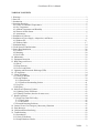
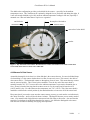
The thermopile for measuring sky temperature is inside the little round can on the sky end of the sensor
head. You can see the filter aperture that lets the infrared radiation enter the device. This device also
contains a thermistor, which is used to measure the temperature of the case around the thermopile. This is
used in the calculations for the sky temperature measured by the thermopile.
4.3 Ambient Temperature and Humidity
At the other end of the sensor head, near the cable connector, is a device that measures the humidity and
the ambient temperature. The dew point temperature is calculated from those two values. This device is
covered with a somewhat delicate white insect and dirt-proof cover. Please do not puncture this. The
sensor head should be positioned so that this ambient-measuring device will actually be at a temperature
near that of the ambient ground temperature.
V0029
5
Cloud Sensor II User’s Manual
The double tube configuration provides a solar shield for the sensors – especially for the ambient
temperature sensor. The Cloud Sensor II is primarily designed for use just before and during the night. It
is not well enough shielded to give fully accurate ambient temperature readings in full sun, especially if
mounted over a hot roof rather than on a pole over vegetation.
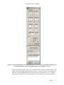
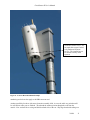
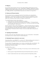
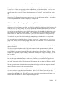
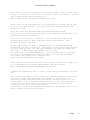
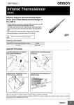
anti-bird wire
anemometer
thermopile with window
wetness sensor
outer tube of solar shield
bracket
Figure 1 - Sky End of the Sensor Head. Recent units have rubber and stainless steel washers under the 4
screw heads on the rain or wetness sensor white disk
4.4 Wetness Or Rain Sensor
Around the thermopile device there is a white disk that is the wetness detector. It senses individual drops
of rain striking it. It also senses whether there is a film of water on it or not. This sensor is also able to
detect snow and ice. The thermopile cannot see through any form of water. This means that any wetness
must be removed quickly. This is done by three methods. First, the sky end of the sensor head is
normally heated to 8C (15F) or more above the ambient temperature to prevent the formation dew or
frost. Second, when the rain stops but the wetness sensor is wet, the sensor head is heated to 60C
(140F) until it is dry. For older firmware the temperature was 70C (158F). Third, the sensor head is
installed at a tilt from the vertical position by the attached bracket so water runs off of the sensor head.
Please note that if you touch or come near the wetness sensor you may get a rain and/or wet indication in
the Clarity II window. And it will last for about 1 minute. This happens because you are mostly made of
water. Any material with a high dielectric constant can look like water to this sensor. Also note that the
sensitivity to rain drops is much higher than that for wetness. It is difficult to distinguish real wetness
from the slow drift due to humidity, dirt, aging, and temperature.
V0029
6
Cloud Sensor II User’s Manual
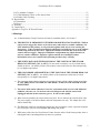
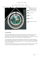
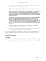
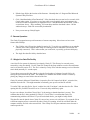
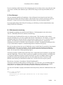
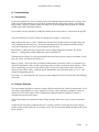
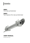
white dot to match to white dot on connector
anemometer connector
humidistat & ambient temperature sensor
daylight sensor (missing
in this photo). For the
newer V014+ board sets
this sensor is on the left
cable connector
serial #
power LED
inner tube of solar shield
Figure 2 - Ground End of the Sensor Head
4.5 Anemometer
The gold finger sticking up from the sensor head is the anemometer. It has adequate accuracy for our
purposes but is less accurate than other designs. It also is omni directional – it does not sense the
direction of the wind. This one has no moving parts, no holes to get blocked, no transducers to fail, and is
reliable under winter conditions. These were the reasons for choosing this design.
The gold finger has a fixed power heater at the bottom and a temperature sensor at the tip of the finger.
By measuring the amount the finger is cooled by the wind, the wind speed is estimated. The gold plating
helps it work in full sunlight by reducing heating by the sun. It is most accurate at the low wind speeds
where observing is possible.
This type of anemometer responds slowly and therefore does not respond to brief gusts of wind. Bear this
in mind when setting the wind speed alarm limit or comparing the results to a weather station.
V0029
7
Cloud Sensor II User’s Manual
5. Installation of Software
The CDROM supplied contains the Clarity II software, the USB drivers, this manual, and the program
TestClarityII. TestClarityII is discussed in section 20. Clarity II requires Windows 2000 or XP.
Vista should work but has not been tested by us. There are customers using Linux but they had to write
their own software. We provide no support of Linux.
By today’s standards, its RAM requirements are modest – under 10 MB. It requires about 50 MB on hard
disk for its log files. In a dual monitor system, the Clarity II windows must be placed on the first monitor
due to Microsoft Visual Basic limitations. Note that only one Cloud Sensor II can be installed on a
computer. It is possible for one Cloud Sensor I and one Cloud Sensor II to be on the same computer.
Install the Clarity II software from the supplied CDROM (check for updates that are posted on
www.cyanogen.com). When you insert the CDROM into your computer, the install program should start
automatically. Just follow its on-screen instructions. If it does not start automatically, please browse the
contents of the CDROM and run the program called “SetupClarityII.exe”.
You might wish to add a Clarity II program shortcut to the Start menu/All Programs/Startup so the Clarity
II program will start when your computer boots.
6. Installation of Power Supply, Adaptor box, and Drivers
Two drivers must be installed for the USB interface. As a part of the software installation, the code for the
drivers was placed into C:\Program Files\BoltwoodSystems\ClarityII\drivers (replace the C: with the
drive your Program Files is on). You must be using Windows 2000 or later.
The information in this section has been derived from the documents provided by FTDI Chip for their
FT232RL USB interface chip that we use in the adaptor box.
If you previously have installed other versions of these drivers you must first remove them. Unplug any
Cloud Sensor II adaptor box, and then use Start/Settings/Control Panel/Add or Remove Programs to find
“FTDI USB Serial Converter Drivers” and do the remove.
Windows removes the references to the USB port drivers whenever the port becomes inaccessible (no
power at the adaptor box, USB cable unplugged, or reboot of the operating system). After installation of
the drivers, Windows will find the driver provided that the adaptor box cable is plugged into the same
USB port, and it is the same adaptor box. If you ever see the procedure below starting after you have
successfully installed, it means that you have plugged into a different USB port or you are using a
different adaptor box.
The power supply works on 90-230 VAC 50-60 Hz. It has been provided with 4 different plug inserts.
There might be a protective piece of plastic where the AC plug insert goes. Remove this open square
protector, if it is there. Install the correct AC plug insert for your area into the power supply. The power
supply automatically adapts to the local voltage and frequency no matter which insert is used. Then plug
in the power supply to the adaptor box and to the building power. Do not at this time plug in anything
else into the adaptor box. The green power LED should come on in a few seconds.
Note that the power supply provided is a 24VDC regulated unit and that is a higher voltage than most
similar units. Do not mix it up with other similar supplies that have the same plug. Do not substitute an
unregulated power supply for the one that comes with the Cloud Sensor II. Do not substitute a noisy
V0029
8
Cloud Sensor II User’s Manual
power supply either. Noise will stop the wetness or rain detector from working properly. The center
contact of the 24V plug is positive.
The driver installation instructions below are those supplied by the maker of the USB interface chip used
(FTDICHIP). Unfortunately Microsoft keeps making changes to Windows and those may cause some
variation from these instructions.
At this point we have to diverge depending upon your operating system:
V0029
9
Cloud Sensor II User’s Manual
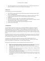
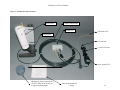
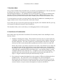
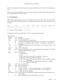
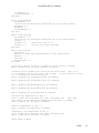
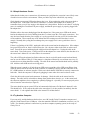
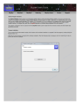
Figure 3 - Cloud Sensor II System Parts
sensor head
cable to sensor head
adaptor box
USB cable to PC
not included
P.S. protector
3 extra P.S. inserts
power supply (P.S.)
shipping cap for the sensor head
sky end. (May not be exactly as
it appears in photograph.)
software & manual CD
V0029
10
Cloud Sensor II User’s Manual
6.1 Windows XP
Temporarily disconnect your computer from the Internet. The simplest and surest way is to remove the
cable to your Internet connection. This is needed because some versions of XP will go to Microsoft
without your permission and download the wrong version of the USB drivers manufactured by FTDI
Chip.
Connect the adaptor box to one of the computer’s USB ports using the supplied A/B USB cable. Choose
the USB port with care because it cannot be changed except by redoing some of the installation procedure
as is explained later.
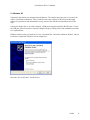
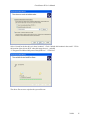
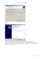
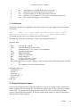
Windows should see the new hardware in a few seconds and the “Found New Hardware Wizard” will run.
It will start to install the USB driver for the adaptor box:
Select the “No, not this time” and click Next.
V0029
11
Cloud Sensor II User’s Manual
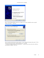
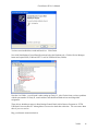
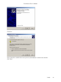
Ignore “EVAL232Board USB” and do not use a floppy or CD. Select “Install from a list or specific
location (Advanced)”. Click Next.
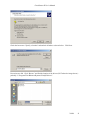
Select “Search for the best driver in these locations”. Check “Include this location in the search”. Fill in
the location of the drivers (NOT where this image shows) – probably
“C:\Program Files\BoltwoodSystems\ClarityII\drivers”. Alternatively you can use the drivers folder on
the distribution CDROM. Click Next.
V0029
12
Cloud Sensor II User’s Manual
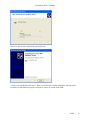
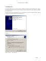
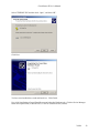
The driver files are now copied to the system file area.
You have now installed the first driver. When you click Finish a similar installation will start for the
second driver that handles the pseudo-serial port so Clarity II can talk to the USB.
V0029
13
Cloud Sensor II User’s Manual
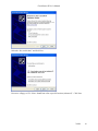
Select the “No, not this time” and click Next.
Do not use a floppy or CD. Select “Install from a list or specific location (Advanced)”. Click Next.
V0029
14
Cloud Sensor II User’s Manual
Select “Search for the best driver in these locations”. Check “Include this location in the search”. Fill in
the location of the drivers (NOT where this image shows) – probably
“C:\Program Files\BoltwoodSystems\ClarityII\drivers”. Click Next.
The driver files are now copied to the system file area.
V0029
15
Cloud Sensor II User’s Manual
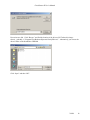
You have now installed the second and last driver. Click Finish.
Now click Start/Settings/Control Panel/System and select the Hardware tab. Click the Device Manager
button and expand Ports (COM and LPT). Look for USB Serial Port (COMx).
Note the x in COMx – you will need it when setting up Clarity II. Also if in the future you have problems
with the port number in Clarity II, come back here and check that Windows has not changed this
assignment.
These drivers should now appear in Start/Settings/Control Panel/Add or Remove Programs as “FTDI
USB Serial Converter Drivers” although there is no need to check that at this time. You can remove them
there if you ever need to.
Plug your Internet connection back in.
V0029
16
Cloud Sensor II User’s Manual
6.2 Windows 2000
Connect the adaptor box to one of the computer’s USB ports using the supplied A/B USB cable. Choose
the USB port with care because it cannot be changed except by redoing some of the installation procedure
as is explained later.
Windows should see the new hardware in a few seconds and the “Found New Hardware Wizard” will run.
It will start to install the USB driver for the adaptor box:
Click Next.
Choose “Search ...” and click Next.
V0029
17
Cloud Sensor II User’s Manual
Do not insert a disk. Click “Browse” and find the location of the drivers (NOT where this image
shows) – probably “C:\Program Files\BoltwoodSystems\ClarityII\drivers”. Alternatively you can use the
drivers folder on the distribution CDROM.
Click “Open” and then “OK”.
V0029
18
Cloud Sensor II User’s Manual
Click Next.
Windows should then display a message indicating that the installation was successful. Click
"Finish" to complete the installation for the serial converter driver for this port of the device. When you
click Finish a similar installation will start for the second driver that handles the pseudo-serial port so
Clarity II can talk to the USB.
V0029
19
Cloud Sensor II User’s Manual
Click Next.
Select "Search for a suitable driver for my device (recommended)" as shown below and then
click "Next".
V0029
20
Cloud Sensor II User’s Manual
Check the box next to "Specify a location" and uncheck all others as shown below. Click Next.
Do not insert a disk. Click “Browse” and find the location of the drivers (NOT where the image shows) –
probably “C:\Program Files\BoltwoodSystems\ClarityII\drivers”.
V0029
21
Cloud Sensor II User’s Manual
Select FTDIPORT.INF and then click “Open”, and then “OK”.
Click Next.
You have now installed the second and last driver. Click Finish.
Now click Start/Settings/Control Panel/System and select the Hardware tab. Click the Device Manager
button and expand Ports (COM and LPT). Look for USB Serial Port (COMx).
V0029
22
Cloud Sensor II User’s Manual
Note the x in COMx – you will need it when setting up Clarity II. Also if in the future you have problems
with the port number in Clarity II, come back here and check that Windows has not changed this
assignment.
These drivers should now appear in Start/Settings/Control Panel/Add or Remove Programs as “FTDI
USB Serial Converter Drivers”. You can remove them there if you ever need to.
V0029
23
Cloud Sensor II User’s Manual
7. Simulation Mode
Once you have installed Clarity II and then run it, it will start up in simulation mode. This uses data from
an old log file (see section 15.3) which was installed in Program Files\Boltwood
Systems\ClarityII\simdata.txt. The simulation runs in real time and there is 22 hours of simulation data
provided. When in simulation mode the Clarity II window will show “SIMULATING” in red. This
mode allows you to try out all of the software features whether you have installed the hardware or not.
To use the hardware you need to exit from ClarityII, rename the file simdata.txt to something else (we
suggest simdatax.txt) so Clarity II cannot find it, and restart ClarityII.
If you wish to use one of your own log files (not a long term log file) as the simulation data file, just copy
it to Program Files\Boltwood Systems\ClarityII\simdata.txt.
This simulation facility can be useful when you are debugging interfaces to other programs.
8. Cloud Sensor II Familiarization
Please follow these steps and test the Cloud Sensor II conveniently indoors before installing the sensor
head out of doors:
a. Unplug the wall plug power supply. This precaution is necessary in case you mis-register the
rectangular connector at the rear of the sensor head. Connect the cable to both the sensor head
and to the adaptor box. The cable is supplied in a coil held together with cable ties. Enough
slack has been left at each end such that you probably do not need to cut the ties at this time.
Remove the protective cap from the sensor head. Be careful. The anti-bird wires are sharp and
are easily bent. Store the cap or block where it can be found in future years. Check that the
anemometer cable is correctly plugged in on the sensor head. This cable runs from the bottom
of the gold finger straight down between the plastic tubes. At the bottom end there is a black
rectangular connector with a white dot on it. It might have come loose during shipping. If so,
match the white dot with the white dot on the circular circuit board at the bottom end. See
Figure 2. Plug the connector onto the pins of the black strip of 4 pins.
b. If not connected, reconnect the adaptor box to the computer’s USB port used during the driver
installation above. The “Roof Close” jack on the adaptor box is not used during this
familiarization but will function in your proper installation. If the sensor head is not yet near
room temperature, leave it until it is. It does not matter in what order you plug things together
or run the software, except as concerns the alignment of connectors noted above.
V0029
24
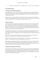
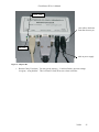
Cloud Sensor II User’s Manual
power LED
your cable to the dome
controller (but not yet)
data LED
cable to power supply
Figure 4 - Adaptor Box
c. Run the Clarity II software. You may get the message, “Could not find any previous settings
in registry - using defaults”. This is normal if Clarity II has never been run before.
V0029
25
Cloud Sensor II User’s Manual
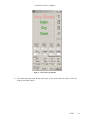
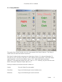
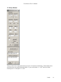
Figure 5 - Clarity II Large Window
d. Click the Setup button at the bottom of the large version of the Clarity II window. This will
bring up the Setup window.
V0029
26
Cloud Sensor II User’s Manual
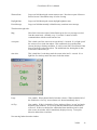
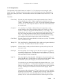
Figure 6 - Clarity II Setup Window. The threshold values shown down are the normal default thresholds. If
your serial number is >= 00577 then the Dark/Light is 121 and Light/V.L. is 220.
e. Enter the COM port number from the driver installation into the “Port” field and click OK. The
yellow LED on the adaptor box should start to flicker. If all is well, after less than 60 seconds
the circle just to the right of Msg in the Clarity II window will flash green every 2.1 seconds
meaning that the computer is receiving signals from the sensor head. If the circle remains red
V0029
27
Cloud Sensor II User’s Manual
or you get “No Msg’s” continuously, check all of the Cloud Sensor II hardware connections
and make sure that you have the COM port number correct.
e. Familiarize yourself with the adaptor box LED behaviour, software, and the various readings
and alerts. After a few seconds, the seven fields near the top of the window should contain
numbers. Aim the sensor head at something that is at room temperature and the top left hand
number should be near zero. If it reads 999.9, wait a couple of minutes for the sensor to heat up
a bit and try again. Aim it at your skin and the number should read either a few degrees
positive or 999.9 (it won’t show your true temperature because it quickly saturates for positive
temperatures, indicating 999.9). Aim it at something taken from your freezer and the number
should be quite negative.
During all of this, the next number field should be showing the air temperature in the room and
after many minutes of warm up, the Wind field should be indicating near 0. After a few
minutes the next field should indicate a temperature that is about 10C (18F) above the
Ambient Temp. If this is true, simulate some “rain” with a sprinkle of water on the white disk
at the sky end of the sensor head. After a while the sensor head should heat until the water
evaporates. The heater will then shut off. NOTE that the sensor head could heat up to a HOT
70C (158F).
Take a look at section 15.1 of this manual and try out the Alert For and Alert Type check
boxes. Become familiar with the various alerts.
When you next power up you might get a long delay (~1 minute) before messages are received
from the sensor head. This is due to Windows and the USB driver.
Please note that Windows 2000’s USB handling is not very robust. If something goes wrong you may
have to power down the adaptor box and restart Clarity II. Windows XP does not have this problem.
9. Sensor Head Installation
9.1 Location
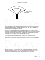
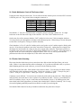
The sensor head must be installed out of doors in a location where it has an unobstructed view of the sky.
It will not work through a glass window. Its field of view is in the shape of a cone with an included angle
of approximately 80°. There is some sensitivity out to 120. Any substantial obstruction in that field of
view will reduce the sensitivity and accuracy of the sensor head.
V0029
28
Cloud Sensor II User’s Manual
Some sensitivity
Main sensitivity
Figure 7 - Cloud Sensor II sky angular coverage
The sensor head is installed with a tilt of 10 (due to its bracket) from the vertical. This tilt allows water
to run off of the surface of the wetness sensor. Otherwise it would take a lot of heating to evaporate that
water. It would be better to lean 10 into the direction from which the prevailing winds blow. This will
allow, in most situations, the sensor head to detect a change in the weather slightly earlier than otherwise.
There is a daylight sensor at the bottom end of the head. It is quite sensitive but it does need to see some
daylight reflected off of the objects and surfaces below for it to work. This would be a problem only if
you deliberately block it or mount it over a black pit.
The sensor head is quite robust but it must not be installed in a polluted, dirty, salt water, or corrosive
environment. Do not place the sensor head anywhere that you would not leave your telescope mirrors and
lenses open at. Your telescope’s expensive mirror, lens coatings and mechanics are only occasionally
exposed - the sensor head is always exposed and therefore more vulnerable.
You should consider the need for maintenance (see section 10) when you chose your position.
Because the rain or wetness sensor and the wind probe can get very hot (70C or 158F), locate the sensor
head such that no one can casually touch it.
9.2 Mounting
The sensor head bracket is designed to be mounted onto a vertical pipe or metal or wood post. One way
to mount it would be to fasten a piece of aluminum channel or angle to the edge of your roof. An even
better location would be on a pole or post positioned over vegetation. In this way the ambient
temperature sensor will not be affected by the heat from your roof or driveway during and after a hot,
sunny day.
There are two mounting holes on the bracket that will take cable ties or #10 screws. If necessary, drill
more holes in the bracket. If you use cable ties, make sure that they are sunlight or UV proof (black
ones), and that the bracket will not slip down your pole as the temperature changes. A few layers of
weatherproof tape just under the bracket on the pole can be used to do this. See Figure 8.
V0029
29
Cloud Sensor II User’s Manual
Make the pole long enough to keep the sensor head well above any snowdrifts – if you get any. The
connector at the end of the cable will corrode if it is left in a puddle of water, especially if it has power on
it. If the snow drifts as high as the bottom of the sensor head, this can happen.
Before leaving the sensor head, please press down gently on the white rain sensor (NOT on the
thermopile window and avoid the anti-bird wires), and make sure that the electronics assembly is fully
seated in the double tube unit. The white disk surface should be about 1/8” or 3 mm. below the edge of
the large white tube. If the electronics assembly moved during shipping, the silicone grease water seal
just under the rain or wetness sensor could have opened up and cause problems during violent rain storms.
9.3 Roof Cable
The cable has been sent to you in a coil without twists in it. To keep it that way you need to cut the two
white cable ties, and then unroll the cable - instead of just holding the bundle and pulling at one end. If
you should ever need to move the cable elsewhere, make sure that you roll it up properly. At one end
make a circle 12” (30 cm) in diameter out of one turn of the cable and tape it. Now “roll” this circle of
cable down the length of the cable gathering it up.
For those who do not already have a convenient hole through an exterior wall for the cable, drill a 15 or
16 mm (5/8”) diameter hole through the wall, making very sure not to drill through any electrical wires or
plumbing pipes. To thread the cable, start with the cable inside. Push a straightened-out metal coat
hanger with the hook at the outside end, from outside to inside. Tape the rectangular connector and 10
cm (4”) of cable to the coat hanger. Pull on the coat hanger. You might need a second person inside to
unroll the cable and to make sure that the cable does not snarl. If you are alone, unroll the cable inside
first before pulling it through the wall. Note that the end of the cable with the small rectangular connector
goes to the sensor head.
If you must use a smaller hole (large enough for the cable itself but without the connector), you can
disassemble the rectangular connector using a very small screwdriver and a lot of care. First push the 5
wires into the connector slightly. This disengages the retaining tabs on the clips. Then you depress the
retaining tab of the clip for each pin. They are visible in each of the rectangular small holes on the longer
side. With the retaining tab depressed you gently pull on the wire and the clip will come out.
Before reassembling the connector you might need to use a small knife to bend each retaining tab upward
slightly. The pinout for the rectangular connector is:
Pin Number
1
2
3
4
5
Twisted Pair
1
1
2
2
Wire
Red
Green
Yellow
Black
Bare
Signal
DataData+
+24V Power
Power Return
Shield
Note that the “1” (for pin 1) molded into the rectangular connector housing is hard to see. It is right
beside one of the side slots at the edge of the connector. Pin 5 has “2695” molded in over it. The same
V0029
30
Cloud Sensor II User’s Manual
electronics release screw – do
not touch this except if asked
to by Boltwood Systems
service. The innards have to
be rotated correctly when
replaced
Figure 8 - A Sensor Head Installation Example
numbering and colours also apply to the DB9 connector end.
Another possibility for those with some electronic assembly skills, is to cut the cable at a point that will
be well indoors when you are finished. Then thread the outdoor portion through the wall from the
outside. Now cut back the covering and shield on both sides of the cut. Slip large heat shrink tubing over
V0029
31
Cloud Sensor II User’s Manual
one end of the cable. Strip the wires and slip small heat shrink over each wire on one side. Solder the 5
wires together matching the colors. Insulate the joints with the heat shrink and shrink it. Slip the large
heat shrink over the entire joint and shrink it.
Make sure that the power supply is unplugged before the next step. This precaution is necessary in case
you accidentally misregister the rectangular connector at the rear of the sensor head, which could damage
the sensor head if power is present. Plug the rectangular connector on the cable into the white connector
on the bottom end of the sensor head. Strain-relieve the cable below and close to the head. Tie the cable
against a flat or convex surface - not the inside of an angle or U channel. See Figure 8 - A Sensor Head
Installation Example.
Fasten the cable to the building or post. If you need cable ties, you should be able to find them in the
electrical section of a hardware store. Use the black version (which should be labeled UV or sunlight
resistant).
Support the cable well enough so that it will not flex in the wind. While the cable is rated to -40C or
-40F, it will be stiffer at low temperatures; you do not want to risk cracking the insulation if it is flexed
or handled. Put a drip loop into the cable before it enters the building so that water running down the
cable cannot run into the hole in the wall.
Bring the cable indoors to near your computer. Plug the sensor head cable into the adaptor box, plug in
the power supply, connect the USB cable to the computer, and you are done. Normally the Cloud Sensor
II is left powered on at all times; this is important for keeping the sensor clear of water and ice.
The adaptor box and power supply are intended to be used at room temperature near your computer. The
power supply is rated for 0C to 40C. The adaptor box is rated for 0C to 70C. This means that you
should avoid operating the power supply in an unheated observatory in very cold winter conditions or in
very hot summer conditions. A -40C rated adaptor box may be available. Check with Cyanogen if you
need it.
10. Maintenance
Cloud Sensor II is designed to be low maintenance. We especially avoided having any moving parts
(such as in a conventional anemometer). We built in a bird deterrent, and powerful heater to remove rain,
ice, and snow.
In extreme winter conditions, the sensor head could develop a cap of snow beyond the reach of the heater.
You would have to brush that off by hand if it happens.
If you get cloudy or very cloudy readings when you know it is clear, inspect the sensor head top end for
an obstruction such as a hollowed out snow cap, leaf, or bird droppings.
Over a long period of time the window to the thermopile in the sensor head can accumulate dirt although
the rain usually washes it clean. The window is a silicon wafer with coatings on it. Gently clean it as you
would clean an optical surface. Blow off any grit with compressed air or a blower bulb first. Unlike an
optical lens, the thermopile is hermetically sealed so you do not have to worry about an excess of fluid.
Just don’t immerse the sensor head.
V0029
32
Cloud Sensor II User’s Manual
Allowable cleaning agents are Kodak lens cleaning fluid (distilled water with a little alcohol and mild
detergent) and 70% to 100% isopropyl alcohol.
11. Equipment Protection
Although the Cloud Sensor II is in part intended to help protect your equipment, you should not use it as
your only means of protection. Proper monitoring of the conditions and the safety of the equipment is the
responsibility of the operator.
Cloud Sensor II is not intended to be the only protection for expensive equipment. It is intended as
a “last resort” to protect your equipment in case of unexpected weather conditions, not as the
primary or sole protection. Significant rain may fall before the observatory is closed. It is extremely
important to monitor local weather conditions, weather forecasts, satellite, and weather radar
before and during observatory operations.
12. Birds, Bugs, and Leaves
12.1 Birds
A couple of customers have had problems with birds perching on the earlier version of the Cloud Sensor
thus intermittently blocking the sensor. The birds also used it as a toilet thus permanently blocking the
sensor! We have added a barrier to the top of the sensor head (11 sharp wires) to discourage the birds. It
still may be possible for a very large owl or other creature to sit on the sensor.
12.2 Bugs (Insects)
The rain and wetness sensor responds to any water that impinges upon it whether the water is liquid or is
incorporated in living matter (actually anything with a high dielectric constant). So large insects can
cause a rain or wetness alarm. This is especially a problem in the spring. If you have this happening
when you are sure that it is dry out, raise your rain and/or wetness thresholds. See section 15.2.
12.3 Leaves And Debris
Similarly organic matter can look like rain or wetness. Leaves will also block the sky sensor. Clean off
the sensor, and if necessary, raise the rain and/or wetness thresholds.
13. Lightning and Electrostatic Discharge (ESD)
Unfortunately many good mounting locations will also attract lightning. The Cloud Sensor II has
lightning protection in the sensor head and in the adaptor box. These should protect against the surge
from nearby lightning hits. They will not protect against a very close or direct hit (nothing simple or
inexpensive will). We do not warranty the sensor head against lightning damage, nor damage to your
building or other equipment due to lightning that the cable might conduct inside, because it is beyond our
control. In high frequency lightning areas an optical isolation device on the USB interface between the
adaptor box and the computer is strongly recommended.
V0029
33
Cloud Sensor II User’s Manual
If the sensor head is vulnerable, place a properly grounded lightning rod nearby and higher than the
sensor head. Also provide a heavy grounding wire from either the sensor head aluminum bracket, or the
metal pole you mount the sensor head on, directly down to a ground rod. A few loops in the cable near to
the cable entrance to the building will also help keep a direct stroke of lightning out of the building.
The same devices that help protect against lightning damage also protect against ESD damage. These
devices route any lightning or ESD energy to the shield of the USB cable and thence to your computer’s
chassis. Your computer needs to be grounded to the power ground (or better) for this to work properly.
If you add your own lightning protection devices to the cable, be sure that the 4800 BPS data on pins 1
and 2 of both connectors (red/green pair in the cable) is not significantly distorted by the protection
devices. If you ever need to update firmware you must pass 38,400 BPS if you use the facility available
in the Setup window. If you have made changes to the supplied roof cable setup, this data rate might be
too high. In that case see section 16.2 and use “Start Bootloader & Download”.
14. 12V Operation
For a customer that had an unusual requirement and was using a very short roof cable, we were able to
adapt units to 12V operation starting at serial #00782. If you want to consider this (and really, really need
it) the maximum cable is 50’ (15 meters), and you would have to provide a low noise well regulated 12V
1A power supply as good as the ones we provide for 24V. The minimum output voltage required is
11.75V. Also, the adaptor box should work at 12V but it has not been tested. Contact Cyanogen.
15. Clarity II Software
This software package runs on your Windows PC and interprets the measurements from the sensor head.
It also allows you to control which events will cause alerts and what those alerts will be. It is named
“Clarity” because it indirectly displays the clarity of the sky above the sensor head.
V0029
34
Cloud Sensor II User’s Manual
15.1 Clarity II Window
The caption of the Clarity II window gives the version number of the Clarity II software. The Clarity II
window shows the latest data from the sensor head.
The Clarity II window displays temperatures in either degrees Celsius (C) or degrees Fahrenheit (F).
The choice is yours, and you set it using the C and F buttons in the setup window. Some fields display
actual temperature. Above left the Ambient Temp. is 3.8C. Other fields contain temperature
differences. In the right hand example, Sky-Amb. Temp. is –3.6C. Similarly you get to choose the units
that the wind speed is displayed in (kph, mph, or m/s).
From top to bottom on the left the items in the window are:
Caption
Gives the Clarity II version number.
Cloud State
Large text field showing the current cloudiness state.
Wind State
Large text field showing the current wind state.
V0029
35
Cloud Sensor II User’s Manual
Wetness State
Large text field showing the current wetness state. Note that a report of Snow or
Snowed occurs if the ambient temp. is below freezing.
Daylight State
Large text field showing the current daylight brightness state.
Error Message
Large text field that normally is blank but may contain an error message.
Then down the right side:
Msg
Has a little circle to the right of it that flashes green for every message received
from the sensor head – normally every 2.1 seconds. It turns red when
communications with the sensor head are lost.
wet square
This is dark cyan if the sensor was wet in the last 2.1 seconds. It is a light cyan if
the sensor was wet in the last minute. This condition is also possible under
extreme dewing or frosting conditions. It easily occurs if the Cloud Sensor II has
been off and has just been turned on. The normal anti-dew heating that is done
will not have taken effect yet.
rain circle
This is dark blue if a rain drop struck the sensor in the last 2.1 seconds. It is a
light blue if a rain drop struck the sensor in the last minute.
Large
User settable. When checked the full window is shown. When unchecked all of
the fields below “On Top” are not shown as is shown immediately above.
On Top
User settable. If this is checked the Clarity window will stay “on top” and not be
hidden by other windows. If it is on top and then minimized, the minimization
will occur. If this was checked, the window had been minimized, and a visual
alert occurs, the window will be immediately displayed on top. To stop this
behavior uncheck the visual alert.
Now moving further down the window:
V0029
36
Cloud Sensor II User’s Manual
Sky-Amb. Temp.
Sky temperature minus ambient temperature. This is near zero for a fully
overcast sky and, say, –25C (-45F) or more negative for a clear sky. When the
sensor is wet, this field shows “wet” because it is impossible to make a sensible
measurement.
This field might saturate to 999. if the sensor head is pointed at something that is
warmer than ambient. It might saturate in the other direction to –999. when it is
pointed at something that is very cold relative to the thermopile case. Some
thermopiles will saturate at –60C. If this happens, be thankful that you have
such skies!
Ambient Temp.
Ambient temperature (from the sensor located at the bottom end of the sensor
head). This serves as an approximation for the near ground temperature.
Sensor Temp.
Temperature of the case of the thermopile.
Rain Heater
This shows how much of the available heater power is being applied to the sensor
head in the last 2.1 seconds.
Wind
Wind speed. Absolute calm can register as a low speed. The accuracy is highest
at moderate speeds. For this application we do not need accuracy at gale speeds
– either you already have locked down the roof or it is already gone! When the
sensor is wet, this field shows “wet” because it is impossible to make a sensible
measurement with this type of anemometer. And you have already closed the
roof anyway (we hope!).
Humidity
Relative humidity.
Dew Pt.
Dew point. This is the temperature at which dew (or frost) will form on surfaces.
Daylight
Brightness of the area under the sensor head in arbitrary units. This will tell you
that the sun is rising at dawn. It can show low values during night-time bad
weather because the ground is bright, or due to moonlight. Don’t forget that the
daylight sensor is pointing towards the ground – you might have some small
pathway illumination lights in view of the sensor.
Requesting...
“Requesting Roof Close” will appear beside “Alert For” when the hardware
signal is given to close the observatory roof (see section 18). This will show for
at least 20 seconds. Note that this does NOT show the state (open or closed) of
your roof because we have no signal to tell us when the roof is open, and we only
know when the Cloud Sensor II tries to close the roof. You probably have other
signals that also will close the roof.
Alert For (user settable):
Clear
Alerts if the Sky-Amb. Temp. is more negative than the Clear/Cloudy Temp.
Cloudy
Alerts if the Sky-Amb. Temp. is more positive than the Clear/Cloudy Temp.
V.Cloudy
Alerts if the Sky-Amb. Temp. is more positive than the Cloudy/V.C. Temp.
Calm
Alerts if the Wind speed is less than the Calm/Windy threshold.
Windy
Alerts if the Wind speed greater than the Calm/Windy threshold and less than the
Very Windy threshold.
V0029
37
Cloud Sensor II User’s Manual
V.Windy
Dry
Wet
Rain
Dark
Light
V. Light
Alerts if the Wind speed greater than the Very Windy threshold.
Alerts if the wetness sensor is dry.
Alerts if the wetness sensor is wet or snow has fallen on the sensor recently.
Alerts if rain drops are falling, or snow is sensed.
Alerts when it is dark out.
Alerts when it is light out (relative to astronomically dark!).
Alerts when it is very light out (relative to astronomically dark!).
The alerts are independent of each other. Some apparently silly combinations are useful – such as
Clear and V.Cloudy. You would use that when light clouds have stopped your observing but you
have left the observatory open because you expect the clouds to blow through quickly.
If you check all boxes in a column, you will get a continuous alert. We have not put in any
protection to avoid this.
Alert Type (user settable):
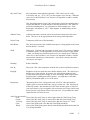
Visual
The top three fields in the window show the current weather status, and are
normally colored green. If this box is checked and there is an alert, the
appropriate text will be shown as light green, pink or red depending upon its
importance.
Beeper
Your computer’s built in speaker is used for alerts. Two different sounds are
used. The first is for a normal alert and consists of 250 msec. 2000 Hz beeps
every 1.4 seconds. A stronger sound is used for wetness and it consists of 700
msec. 500 Hz beeps every 1.4 seconds.
Sound
Your computer’s sound card is used to generate the alerts. A wetness alert is
emphatic.
You may use any or all of the alert types at the same time.
Setup Button
The setup information is entered into a separate window which is reached with
this button.
V0029
38
Cloud Sensor II User’s Manual
15.2 Setup Window
The top section is for setups and the bottom section is for firmware downloading. The threshold values
shown down are the normal default thresholds. If your serial number is >= 00577 then the default
Dark/Light is 121 and Light/V.L. is 220.
V0029
39
Cloud Sensor II User’s Manual
15.2.1 Setup Section
The temperature values in this window are in either C or F as chosen by the user using the “radio
buttons” provided. Similarly the wind speed values are in km/h (kilometers per hour), mph (miles per
hour) or m/s (meters per second). All items in this section are user settable except “Ser # WC SC” and
Firmw.V.
Thresholds:
Clear/Cloudy
When the Sky-Amb. temperature is more negative than this value, Clarity II
declares the sky to be "clear". When it is more positive than this, the sky is
"cloudy". The default value is -25C (-45F). As you gain experience with using
Clarity II you may wish to adjust this number to better suit local conditions and
the current season.
Cloudy/V.C.
V.C. stands for “Very Cloudy”. When the Sky-Amb. temperature is more
negative than this value, Clarity II declares the sky to be "cloudy" (or “clear” –
see above). When it is more positive than this, the sky is "very cloudy". The
default value is -10C (-18F). As you gain experience with using Clarity II you
may wish to adjust this number to better suit local conditions and the current
season. Very cloudy skies are the kind which can quickly degrade into raining
skies, and there is no point in trying to observe when it is that cloudy.
Calm/Windy
When the Wind speed is greater than this, it is windy or very windy. The default
value is 15 km/h or 9.3 mph.
Windy/V.W.
This is the Windy/Very Windy threshold. If the wind speed is greater than this, it
is very windy. The default value is 30 km/h or 18.6 mph.
kph mph m/s
Select the units for wind speeds from kilometers per hour, miles per hour, and
meters per second.
Dark/Light
When the daylight sensor reading is greater than this it is light to very light and
you probably cannot observe. Note that units with serial numbers <577 had 11
times lower gain and therefore lower thresholds. The default value is 12 for the
earlier units and 121 for the current units.
Light/V.L.
This is the Light/Very Light threshold. If the light level is greater than this, it is
possible that the sun is up, and perhaps it is frying your telescope innards. When
this threshold is passed, the emergency roof closure will be activated.
If you wish to use your observatory during the day (planets, birds, tests, ...) you
can raise this threshold to >= 1024 thus deactivating this as a roof closure cause.
Failure to note this section causes calls for service when the roof closes when the
sun is up. Normally the Cloud Sensor II closes the roof in daylight. Please
remember.
Note that units with serial numbers <577 had 11 times lower gain for “Daylight”
and therefore lower thresholds. The default value is 20 for the earlier units and
220 for the current units. If you do twilight flats for your CCD camera, you
probably will have to raise the default threshold to avoid having the roof close.
V0029
40
Cloud Sensor II User’s Manual
Rain
This is the threshold for separating the impulse in the rain detector for a rain drop
from noise. The units are arbitrary. Raise this value if you get too many rain
alerts when there is no rain. Note that rain detection is heavily filtered to avoid
alerts from bugs and particles of dirt. Your bugs might be bigger and more
frequent than ours. Usually spring time is bad for bugs. The default value is 12.
Wet
This is the threshold for deciding whether the wetness sensor is wet. The units
are the same as for “rain”. The default value is 100.
Port
This allows you to inform Clarity II as to which pseudo-serial port the Cloud
Sensor II is connected to. You should have recorded this number when you
installed the USB driver.
Ser# WC SC
This field provides information about the sensor head. Ser# is the serial number.
WC=1 if the wetness and rain sensor has been calibrated (and should always =1
for a customer sensor head). SC=1 if the thermopile sensor has been calibrated
(and should always =1 for a customer sensor head). When Clarity II is first
started it can take up to 105 seconds for these values to appear.
Firmw. V.
Firmware version number for the software in the CPU in the sensor head. When
Clarity II is first started it can take up to 105 seconds for this value to appear.
Data File Button
A command button that calls up a Windows Open File dialog box to allow you to
set a data file path and name. Make sure that this file is not being written by any
other program. Make sure that it is always accessible to ClarityII.exe. See
Section 17.1.
New/Old
Sets the data file format. See Section 17.1.
OK
To implement any changes.
Cancel
To ignore and discard any changes.
15.2.2 Firmware Downloading Section
The sensor head’s CPU program memory is in two sections: a boot loader and the current firmware. The
boot loader is protected from accidental erasure or corruption so if something goes wrong in the
procedure below, just start it over again.
Get Firmware File
A command button that calls up a Windows Open File dialog box to allow you to
set the location of the firmware. Normally that is C:\Program Files\Boltwood
Systems\ClarityII\cs2.hex. You must do this before going any further here.
Load Firmware
Prepares to overwrite the firmware in your sensor head.
Yes
If you are sure you want to proceed.
No
If you do not want to proceed.
V0029
41
Cloud Sensor II User’s Manual
After pressing Yes the download will start and the Boot Loader version will appear in one field and a
progress report with a decreasing line count will appear in the other field. “Successfully Downloaded”
will appear when done and the sensor head will go back to normal operation. Click OK to get rid of the
Setup window.
This firmware download is done at 38,400 BPS. If you have made changes to the supplied roof cable
setup, this data rate might be too high. In that case see section 16.2 and use “Start Bootloader &
Download”.
There is a possible communications conflict when pressing Yes to start the download. If it does not start
just press Load Firmware and Yes again.
15.3 Log Files
These are Boltwood Systems main means for providing service for you. A great deal of information that
is useful to us is in these files. Our experience has shown us that there usually isn’t any point in our
attempting to solve most technical problems without these log files.
Log files are written in an automatically generated directory similar to:
C:\Documents and Settings\username\My Documents\ClarityII\. This directory must be used exclusively
for these log files. Old log files are automatically deleted from this directory without warning.
One text file is created for each day of running with a name similar to: “2006-06-07.txt”
which is formatted as yyyy-mm-dd.txt. One line is written in this file for every message sent to/from the
sensor head. 5 days worth of these log files are kept.
There is also a “longtermlog.txt” file using the same format with one line every 30 minutes. That file
grows indefinitely. You are permitted to edit it to a smaller size with a text editor (not a word processor),
but please only if you have too. This long term view is often useful when servicing.
The daily files are somewhat large (approximately 8 MB) but they compress by about 10 times when
zipped - which is what should be done when sending them to the factory as email attachments if support
is needed. With today’s hard disk capacities, the space taken by the 5 log files is not a large burden.
These 5 files allow the examination of problems that occurred up to 5 days ago PROVIDING THAT
YOU COPY THE FILE TO SOMEWHERE ELSE BEFORE IT IS AUTOMATICALLY DELETED.
The log files are in ASCII and you probably can figure out what many of the fields mean if you are
curious. See Appendix A for a partial description of the “D” records in the current log files. These files
are generated solely for Boltwood Systems use when doing servicing. The format is not guaranteed to
remain unchanged and it is only partially documented. See sections 17.1 and 20 for user ways to properly
access the data rather than by using the log files.
If you are reporting a problem, be sure to include the relevant log file(s) and the longtermlog.txt file all
zipped together. Attach the zip file to your report. If you don’t, and don’t provide a valid reason, NO
LOG FILES – NO SERVICE. Sample valid reasons from past customers:
I dropped the sensor head off a 3 storey building onto the pavement
My lawnmower ate the cable
I lost the adaptor box.
Please do not simply copy the log file into your email. It must be as an attachment or we cannot read it.
V0029
42
Cloud Sensor II User’s Manual
15.4 Registry
Every time the Clarity II program is closed or a Setup field is changed, Clarity II preserves the user
changeable information in the registry at “My Computer/HKEY_CURRENT_USER/Software/VB and
VBA Program Settings/BoltwoodSystems/ClarityII”. These values are reinstated next time Clarity II is
run. Fiddling with these, except under Boltwood Systems service direction, is not a good idea.
16. Software and Firmware Updates
The Cloud Sensor II can be reprogrammed in the field. This will allow you to download future
enhancements. We advise you to check the www.cyanogen.com web site occasionally to see what
improvements are there. This is especially necessary if you are having any problems. Please do an
update before contacting us about a problem; we might have already fixed it.
You can check what your current version numbers are:
Clarity II shows its version in the caption line of its window.
the firmware version shows in the setup window in the field Firmw. V. This comes from the
sensor head and is only reported every 105 seconds or so. If you have just started up, you might
have to wait a bit for it. See section 15.2
The file on the Internet will be called “SetupClarityII.exe”. This file will contain Clarity II, TestClarity
II, the latest firmware, a firmware loader, USB drivers, and the latest version of this manual. When you
execute SetupClarityII.exe all of this software will be installed in C:\Program Files\Boltwood
Systems\ClarityII. The firmware will be in CS2.hex. Be sure to read any readme.txt file present (use
Notepad).
16.1 Updating Clarity II Software
Note the Com Port value in the ClarityII Setup window just in case it is needed below. Then install the
new ClarityII version as is shown in section 5. Read the readme file.
16.2 Updating Firmware (obsolete for most cases)
The procedure below is now OBSOLETE – see section 15.2.2. It has been left here just in case there is a
problem with the new method or your roof cable setup cannot operate at 38,400 BPS.
The sensor head’s CPU program memory is in two sections: a boot loader and the current firmware. The
boot loader is protected from accidental erasure or corruption so if something goes wrong in the
procedure below, just start over again.
The OBSOLETE procedure is:
1. Make sure that ClarityII.exe is not running. This is necessary to avoid a conflict in the use of the
COM port.
2. Run the program C:\Program Files\Boltwood Systems\ClarityII\CSII_Firmware_Loader.exe.
3. Set the Com Port Selection to the same value that you had in the ClarityII Setup window.
V0029
43
Cloud Sensor II User’s Manual
4. Edit the large field to the location of the firmware. Normally that is C:\Program Files\Boltwood
Systems\ClarityII\cs2.hex.
5. Click “Start Bootloader & Fast Download”. If the download does not start in a few seconds, click
Cancel and try again. If you have a very long cable or an electrically noisy environment or an
unusual roof cable configuration you might need to use “Start Bootloader & Download” which is
several times slower. “lines remaining” will count down until the download is done. OK the
window that says “Flash File successfully downloaded”.
6. Now you can start up ClarityII again.
17. Remote Operation
The Clarity II program has no special awareness of remote computing. It does however have some
features that will help:
The COM or ActiveX interface detailed in section 20. To use this you would have to run suitable
software in the same computer that Clarity II is running in (and to which the Cloud Sensor II is
physically connected). This is software that you would write, or possibly get from a third party.
The single line data file facility described next.
17.1 Single Line Data File Facility
A one line file for current sky data may be written by Clarity II. This file may be accessed across
networks by using file sharing. Use the "Data File" button in the Setup window to set the file and format
used, as is shown in section 15.2. The file is written by Clarity II for each data message received from the
sensor head (normally 2.1 seconds apart).
Your software may parse this line either by using the fixed number of columns for each field, or by
sensing the spaces between the fields. The intention is to maintain this format in future revisions by
placing any changes as extra fields at the end of the line.
Clarity II (written in Microsoft Visual Basic 6) opens the file with "Output Lock Write", writes the line,
and then closes the file. This might mean that occasionally your open to read the file will fail.
To read in VB6, open this file for “Input", read the line with "Line Input", and then close the file. When
opening this file you MUST check for errors. If errored, delay and then try again.
In your own software, check that "Now() Day's" is advancing (or that the date/time is recent). This
confirms that the file is being updated by Clarity II. Check "Since" to confirm that Clarity II is
communicating with the sensor head. If you do not do both checks, you might be badly misled.
This data file must be placed where Clarity II is sure to have access to it at all times. If you put the file on
a different computer across a network from where Clarity II is running, all will be well until either the
computer with the file fails or the network fails. Then Clarity II will report continuous errors because it
cannot open the file.
V0029
44
Cloud Sensor II User’s Manual
When run, TestClarityII (section 20) shows the contents of this one line file each time TestClarityII does a
poll.
There are two formats available for the line in the file, selected by the radio buttons underneath the “Data
File” command button in the Setup window:
17.1.1 New Format
This recommended format gives access to all of the data Cloud Sensor II can provide. The data is similar
to the display fields in the Clarity II window. The format has been split across two lines to make it fit on
this page:
Date
Time
T V
2005-06-03 02:07:23.34 C K
SkyT
-28.5
AmbT
18.7
SenT
22.5
Wind Hum
45.3 75
DewPt Hea
10.3
3
R W Since Now() Day's c w r d C A
0 0 00004 038506.08846 1 2 1 0 0 0
The header line is here just for illustration. It does not actually appear anywhere.
The fields mean:
Heading
Col’s
Date
1-10
Time
12-22
T
24
V
26
SkyT
28-33
AmbT
SenT
35-40
41-47
Wind
49-54
Hum
DewPt
Hea
R
W
Since
Now() Day's
56-58
60-65
67-69
71
73
75-79
81-92
c
94
Meaning
local date yyyy-mm-dd
local time hh:mm:ss.ss (24 hour clock)
temperature units displayed and in this data, 'C' for Celsius or 'F' for Fahrenheit
wind velocity units displayed and in this data, ‘K’ for km/hr or ‘M’ for mph or
'm' for m/s
sky-ambient temperature, 999. for saturated hot, -999. for saturated cold, or –998.
for wet
ambient temperature
sensor case temperature, 999. for saturated hot, -999. for saturated cold. Neither
saturated condition should ever occur.
wind speed or:
-1. if still heating up,
-2. if wet,
-3. if the A/D from the wind probe is bad (firmware <V56 only) ,
-4. if the probe is not heating (a failure condition),
-5. if the A/D from the wind probe is low (shorted, a failure condition) (firmware
>=V56 only),
-6. if the A/D from the wind probe is high (no probe plugged in or a failure)
(firmware >=V56 only).
relative humidity in %
dew point temperature
heater setting in %
rain flag, =0 for dry, =1 for rain in the last minute, =2 for rain right now
wet flag, =0 for dry, =1 for wet in the last minute, =2 for wet right now
seconds since the last valid data
date/time given as the VB6 Now() function result (in days) when Clarity II last
wrote this file
cloud condition (see the Cloudcond enum in section 20)
V0029
45
Cloud Sensor II User’s Manual
w
r
d
C
A
96
98
100
102
104
wind condition (see the Windcond enum in section 20)
rain condition (see the Raincond enum in section 20)
daylight condition (see the Daycond enum in section 20)
roof close, =0 not requested, =1 if roof close was requested on this cycle
alert, =0 when not alerting, =1 when alerting
17.1.2 Old Format
This format is provided for compatibility with software written to use the original Cloud Sensor product.
The format is:
Date
Time
U
SkyT AmbT SenT Hea W Since Now() Day's S
2005-06-03 02:07:23 C -28.5 18.7 22.5
3 0 00004 038506.08846 1
The immediately above line is an example of the only line in the file.
The header line is here just for illustration. It does not actually appear anywhere.
The fields mean:
Date
Time
U
SkyT
AmbT
SenT
Hea
W
Since
Now() Day's
S
local date yyyy-mm-dd
local time hh:mm:ss (24 hour clock)
temperature units, 'C' for Celsius or 'F' for Fahrenheit
sky-ambient temperature
ambient temperature
sensor case temperature
heater setting in %
wet flag, =0 for dry, =1 for wet
seconds since last valid data
date/time given as the VB6 Now() function result (in days) when Clarity II last wrote this
file
sky condition (see the SkyCond enum below).
Public Enum SkyCond
skyUnknown = 0
skyClear = 1
skyCloudy = 2
skyVeryCloudy = 3
skyWet = 4
End Enum
17.2 Potential Remoting Problems
If you operate the computer that Clarity II is running on via some form of remote console software from
another computer, there can be problems. The Clarity II executable has to be run in order to give alarms
when needed. The operating system might not allow Clarity II any CPU cycles when the operating
system or a privileged program crashes, or when the remote console software is waiting for the Internet
link to update the remote computer.
V0029
46
Cloud Sensor II User’s Manual
To see if you have the latter problem, examine a log file (section 15.3). There should be a log line every
2 seconds or so. If there are large gaps and then sudden bursts, you have the problem. Be sure to check
this if you have a radio link. Clarity II attempts to alleviate this problem by reading the sensor head
messages much faster (every .25 seconds) than the messages are produced. Thus Clarity II can “catch
up”.
This is a safety problem for your observatory but I am afraid that it is beyond the scope of the Cloud
Sensor II to fix it. The emergency contact closure (section 18) will still function properly – this problem
is part of why that function was made completely PC independent.
18. Contact Closure For Emergency Observatory Shutdown
The 3.5mm mono audio jack on the adaptor box provides a way of performing an emergency observatory
shutdown even if your computer has failed. On each 2.09 second cycle, if the sensor head is seeing a very
cloudy sky, it is very windy, raining, wet, or very light outside, the inner conductor of the jack is shorted
to the outer shell. Clarity II stretches the display and ActiveX versions of this to 20 seconds to ensure that
it is seen but the stretching does not occur for the contact closure. The thresholds for this decision are the
same as the ones in the Clarity II setup window. This contact closure can be used indirectly to activate
shutter motors, etc. At all other times when there is power, the inner conductor is floating electrically.
You can defeat any part of this decision making by manipulating the thresholds in the setup window.
Care was taken in the design of this facility to handle “power is off”, “power is going up”, and “power is
going down” sensibly. Power off and going up do not cause a roof close order. Power going down does
order a roof close for several seconds after the power is lost.
To use this facility you need to have some knowledge of electronics in order to connect it properly to your
dome/roof hardware.
The sleeve (or ring in telephone-speak) of the jack is connected to the ground connection (shell and
shield) of the USB connector – and that will be connected to your computer’s ground, and then normally
to the building’s power ground when the USB cable is plugged into your computer’s USB port. If your
computer is not grounded (a laptop running on batteries or separate power supply for example), you may
have a problem.
Your dome/roof hardware must ground the sleeve of the plug that you will be plugging into the adaptor
box, and the dome/roof hardware must go to the same ground as the computer that the adaptor box is
connected to. If there is any doubt, please use a voltmeter and check that there is no significant voltage
(AC or DC) between the shell of the adaptor box USB connector and your dome/roof hardware chassis.
If your dome/roof hardware’s circuit does not ground one side of the roof close contact connection (all or
most do), you must add an electromechanical relay and power supply between the adaptor box and the
dome/roof hardware to provide the necessary isolation.
Your circuit must put between 0V and +27V on the inner (or tip in telephone-speak) conductor of the jack
via a series resistor or some other form of impedance. There is a 30V transorb across the jack for
electrostatic discharge (ESD) and lightning protection. Your circuit must not allow more than 150 mA of
current to flow through the jack. Note that if you grossly exceed this current limit, you will burn out a
transistor inside the adaptor box – there is no protection against this.
V0029
47
Cloud Sensor II User’s Manual
If you are checking out this function with an ohmmeter please be sure that you have your probes the right
way around. Note that some ohmmeters put a NEGATIVE voltage on the red probe and that will not
work.
19. Error Messages
The error messages should be self-explanatory. Some will appear in a message box and some in the
bottom large text field in the Clarity II window. Some that are only of concern to the factory appear in
the log file. Clarity II will recover from almost all errors that are not due to hardware failures.
If you plug/unplug things while Clarity II is running, you will often get various communications errors.
Clarity II will recover from those.
20. COM Automation Interfacing
Note that this has nothing to do with the serial COM port. COM Automation is also referred to as
ActiveX. Thank Microsoft for the confusion in terminology.
This describes the CloudSensorII class (class is a software term). This class allows other software
programs (including ones you write) to gather data from the Cloud Sensor II. For instance, you may want
a program to park your telescope and close your observatory’s dome/roof if it is very cloudy or rain is
detected. The following are the properties available in the CloudSensorII class. Note that all
temperatures are always in Celsius here and wind speeds are in km/hr. SecondsSinceGoodData provides
a way to check that the computer is communicating with the Cloud Sensor II properly.
Please be sure that you know how to use COM before you try it with Clarity II, especially if your program
is multithreaded or exits processes illegally. Obscure problems arise that look like Cloud Sensor II
failures but aren’t, if you break the rule that an object must be created, used, and deleted on the same
thread. We do not provide COM programming support.
TestClarity II (which is installed along with Clarity II) is a simple Microsoft Visual Basic 6 program that
uses this COM facility. The source code as well as an executable is provided, and these are installed into
C:\Program Files\Boltwood Systems\ClarityII\TestClarityII. We have run multiple instances of this
program with various repeat poll periods for days at a time without any errors. If you have COM
problems with ClarityII, you should look elsewhere first. You have the code to try this yourself.
Please do use: Set cloud = CreateObject("ClarityII.CloudSensorII")
as shown in TestClarity II and not New to create the object. If you use New, your executable might not
work with the next version of Clarity II because VB6 might change the class ID when we recompile
Clarity II here. At Cloud Sensor II’s low data rates, there is no efficiency need to use New.
The ActiveX Visual Basic 6 property declarations taken nearly directly from the CloudSensorII class code
are:
Public Enum CloudCond
cloudUnknown = 0
'Those below are based upon thresholds set in the setup window.
cloudClear = 1
V0029
48
Cloud Sensor II User’s Manual
cloudCloudy = 2
cloudVeryCloudy = 3
End Enum
Public Enum WindCond
windUnknown = 0
'Those below are based upon thresholds set in the setup window.
windCalm = 1
windWindy = 2
windVeryWindy = 3
End Enum
Public Enum RainCond
rainUnknown = 0
'Those below are based upon thresholds set in the setup window.
rainDry = 1
rainWet = 2
'sensor has water on it
rainRain = 3
'falling rain drops detected
End Enum
Public Enum DayCond
dayUnknown = 0
'Below are based upon thresholds set in the setup window.
dayDark = 1
dayLight = 2
dayVeryLight = 3
End Enum
'Clarity II version string as it appears in the Clarity II window.
Public Property Get ClarityIIVersion() As String
'Firmware version number last read from the sensor head. This is in
'a "T" message that is sent every ~100 seconds. If this function is zero,
'no "T" message has been received yet.
Public Property Get FirmwareVersion() As Integer
Public Property Get CloudCondition() As CloudCond
Public Property Get WindCondition() As WindCond
Public Property Get RainCondition() As RainCond
Public Property Get DayCondition() As DayCond
'Relative sky temperature in deg. C.
'This is 999. when saturated hot, -999. saturated cold. -998. when
'the sensor is wet and the sky temperature therefore is unknown.
Public Property Get RelSkyT() As Double
'Ambient temperature in deg. C.
Public Property Get AmbientT() As Double
'Thermopile case temperature in deg. C.
'This is 999. when saturated hot, -999. saturated cold.
Public Property Get SensorT() As Double
'Wind speed in km/hr.
V0029
49
Cloud Sensor II User’s Manual
'-1. if still heating up,
'-2. if wet,
'-3. if the A/D from the wind probe is bad (firmware <V56 only) ,
'-4. if the probe is not heating (a failure condition),
'-5. if the A/D from the wind probe is low (shorted) (firmware >=V56 only),
'-6. if the A/D from the wind probe is high (no probe) (firmware >=V56 only).
Public Property Get Wind() As Double
'Relative humidity in percent.
Public Property Get HumidityPercent() As Double
'Dew point in deg. C.
Public Property Get DewPointT() As Double
'Daylight level in arbitrary units.
Public Property Get DayLightV() As Integer
'Did a rain drop fall in the last 2.1 second cycle?
Public Property Get RainF() As Boolean
'Was the sensor head wet in the last 2.1 second cycle?
Public Property Get WetF() As Boolean
Public Property Get HeaterPercent() As Double
'Clear/cloudy threshold from the setup window in deg. C.
Public Property Get CloudyThreshT() As Double
'Cloudy/very cloudy threshold from the setup window in deg. C.
Public Property Get VCloudyThreshT() As Double
'Calm/windy threshold from the setup window in km/hr.
Public Property Get WindyThreshSpeed() As Double
'Windy/very windy threshold from the setup window in km/hr.
Public Property Get VWindyThreshSpeed() As Double
'Dark/light threshold from the setup window.
Public Property Get DayThreshV() As Double
'Light/very light threshold from the setup window.
Public Property Get VDayThreshV() As Double
'No rain/rain drops threshold from the setup window in arbitrary units.
Public Property Get RainThreshV() As Integer
'Not wet/wet threshold from the setup window in arbitrary units.
Public Property Get WetThreshV() As Integer
'Are the displayed temperatures in Fahrenheit or Celsius?
'Note: all ActiveX and logged temperatures are always in Celsius.
Public Property Get Fahrenheit() As Boolean
'Are the displayed wind speeds in km/hr, mph, or m/s?
'=0 for km/hr, =1 for mph, =2 for m/s.
'ActiveX and logged speeds are always in km/hr.
Public Property Get WindUnits() As Integer
V0029
50
Cloud Sensor II User’s Manual
'See if data is arriving properly from the sensor head. There is data about
'every 2.1 seconds so allow, say, 10 seconds in order to not report a failure
'due to bad messages from lightning, etc.
Public Property Get SecondsSinceGoodData() As Long
'Return true if the data behind all of the properties is ready and the data
'file has just been written. Clear this flag until the next sensor head
'message is ready.
'
'Once this goes true the data must acquired before they change.
'The poll cycle time plus the accessing of the properties and the data file
'should not exceed 1.5 seconds.
'
'The use of this function is optional. If it is not used, some of the
'property data might be from a different sensor head message. That
'should not matter very much.
'
'A day long attempt was made to implement this in the modern Microsoft
'decreed VB way using collections. Then dynamic arrays were tried. Neither
'could be made to work. The VB6 lousy debugging for COM plus crashes did
'not help. A 1960's-style 100 element array of flags
'was then used. It worked immediately. This does mean that no more than
'a total of 100 CloudSensorII.Class_Initialize's can be done throughout
'the life of one instance of a ClarityII.exe.
Public Function DataReady() As Boolean
'This property is true when the roof close signal is sent by the adaptor box.
'It is stretched to 20 seconds approximately and then cleared.
Public Property Get RoofCloseRequested() As Boolean
'Command the observatory roof to close via the facility described in section
'18.
'
'Note however this might not be a good way to get an emergency roof closure.
'For this to work, many things must work properly. PC power, PC, PC
'operating system, software running the script, ClarityII, and all of the
'Cloud Sensor II up to the sensor head and back. If you have some sensor
'(other than the Cloud Sensor II) giving the warning, a direct contact
'closure to close the roof would be safer.
'The function result shows whether the message was successfully sent or not.
Public Function RoofClose() As Boolean
V0029
51
Cloud Sensor II User’s Manual
21. Troubleshooting
21.1 Introduction
If your Cloud Sensor II is “sick”, not dead (Clarity II is displaying data and messages are arriving), then
please first check this manual to be sure that the Cloud Sensor II is being used properly, especially the
setup window. Reports of wetness and/or rain when it is dry and daylight when you think it is dark are
usually setup window threshold problems.
If you cannot solve the problem by reading the manual, please read section 15.3 and send us the log files.
If the Cloud Sensor II is “dead” (Clarity II is displaying “No Msg’s”) read on here.
Many problems that cause a “dead” Cloud Sensor II can be fixed by the user thus saving the delay and
costs of shipping the unit back to us. Even more important, some of the problems checked for below
would not be apparent to us even if you did send the unit back to us.
Beyond the AC input to the power supply, there are no voltages dangerous to humans. Be careful
however – creating shorts could be dangerous to the Cloud Sensor II.
If during these procedures you feel uncomfortable about carrying on, please contact us and either we will
help you or have you ship the unit back to us.
Before you start – did it work when you did the familiarization in section 8? Did it ever work after you
did the full installation? Did you make some change between when it worked and when it didn’t? These
answers might help you figure out the problem, and if you fail to fix the problem, please tell us these
answers in your failure report. Attach the log file that includes where the failure starts (see 15.3). Also
include the longtermlog.txt file.
If you don’t , we will simply have to send you an email asking for the answers and log files thus delaying
your repair.
21.2 Clarity II Problems
The most common problem is to have the wrong COM Port number in the Clarity II setup window. Even
if you had it right originally, it can get forgotten if you have registry problems or Windows screws up.
Clarity II resets all of its registry values including the COM port number to defaults if it detects a
corruption in our part of the registry.
If this is the problem, just update the Clarity II Setup window fields to the correct values and it should
work.
At this time the only known condition that causes a registry problem is an attempt to put the Clarity II
window on the second monitor in a two monitor set up. We do not support that because Microsoft Visual
Basic 6 doesn’t.
V0029
52
Cloud Sensor II User’s Manual
21.3 Simple Hardware Checks
Other than the indoor power connections, all connectors are gold plated so corrosion is not a likely cause
of trouble in non-corrosive environments. When you find a step below which fails, stop testing.
Check that the green power LED on the adaptor box is on. If not, unplug the cable to the sensor head at
the adaptor box. If the LED is still not on, either there is a failure in the adaptor box (unlikely), or
somewhere from your AC line supply to the adaptor box is the problem. Please be sure that AC wall plug
power is reaching the Cloud Sensor II power supply, and that the power supply is properly plugged into
the adaptor box.
With the cable to the sensor head plugged into the adaptor box, if the green power LED on the sensor
head or the adaptor box is slowly flashing, then there is a short across the +24V supply somewhere. You
may also hear sounds from the power supply as it cycles on and off as it tries to recover from the short
circuit condition. These sounds may occur without the LED coming on at all if the short is severe
enough. Normally this cycling does not damage the power supply but it is not a good idea to leave it
happening.
If there is no flashing of the LED’s, unplug the cable to the sensor head at the adaptor box. If the adaptor
box green LED is now on, there is a short across the +24 volt power either in the cable or at the sensor
head. Turn off the power and then plug the cable back into the adaptor box. Unplug the cable at the
sensor head. Turn on the power. If the green LED on the adaptor box comes back on, then the short is in
the sensor head. Otherwise it is in the cable or its connectors.
The yellow LED on the adaptor box flashes whenever data is received from the sensor head and then is
sent on over the USB to Clarity II. If the pattern is a long burst followed by several short ones every 2.1
seconds, then everything should be working. The cable to the sensor head and the head itself is probably
OK. And the sensor head must be receiving power.
When the power is turned on, if only the green LED comes on and the yellow LED never flickers, then
either the sensor head or the cable to it has a problem, or something is wrong with the USB cable or the
PC’s USB hardware or software interface. In this case check that the USB cable is correctly connected at
both ends. Check the computer’s USB port by plugging in some other device and see that it works.
Check the cable to the sensor head connectors for damage. Check the cable to the sensor head for
damage. The cable itself is vulnerable to damage from garden shears, shovels, etc. At the sensor head,
the connector might have been completely or partially unplugged – especially if it was not properly stress
relieved near the sensor head (see Figure 8).
The sensor head has a green power LED at its bottom end which runs off of the head’s internal 5 volts.
This should be lit. If not, suspect the cable to the sensor head. It is also possible, but unlikely, that the
sensor head’s +5 volt regulator has failed or the internal 5V rail has shorted.
21.4 Try Another Computer
If you can easily, and the hardware checks above were OK, install Clarity II on another computer and
plug the Cloud Sensor II into a USB port. After the automatic USB driver installation (section 6), see if it
works. If so then the problem is somewhere in your other computer, operating system, or the setup of
Clarity II on it.
V0029
53
Cloud Sensor II User’s Manual
21.5 Cable Multimeter Check At The Sensor Head
Unplug the cable from the sensor head. You are allowed do this with the power on but do NOT reconnect
it with the power on. The pin out for the rectangular connector is:
Pin Number
1
2
3
4
5
Wire
red
green
yellow
black
bare
Signal
DataData+
+24V Power
Power Return
Shield
Note that the “1” (for pin 1) molded into the rectangular connector housing is hard to see. It is right
beside one of the side slots at the edge of the connector. Pin 5 has “2695” molded in over it.
On the same face of the connector that has “2695” molded on it, there are 5 little rectangular windows.
You can probe the pins through these windows with multimeter probes. When doing so, do not short pins
to each other via the probes. Doing so could be disastrous.
Check that there is 22 to 25 volts DC with the positive (red) probe on pin 3 and the negative (black) probe
on pin 4. If not, then the problem is not in the sensor head. In that case, unplug the power supply from
the adaptor box and measure the voltage on the power supply cable connector. From center (positive or
red probe) to the outer sleeve (negative or black probe) should be 22 to 25 volts DC. If not, either there is
no power at the AC socket or the power supply has failed. If the 22 to 25 volts is present then the
problem must either be in the adaptor box, or the cable to the sensor head.
21.6 Further Cable Checking
Please note that the checks that you have carried out above did not check the Data-/Data+ pair in the
cable. If there is any chance that the cable was damaged, or if you have modified the cable, or you have
added lightning protection to the cable run, you need to do the following checks.
Unplug both ends of the cable. Start with the easier check for shorts. You can check for shorts at either
end of the cable with a multimeter set for ohms. Check pin 1 to pins 2, 3, 4,and 5. Then pin 2 to pins 3,
4, and 5. Then pin 3 to pins 4 and 5. Finally pin 4 to pin 5. All should be open.
Continuity is more difficult. You need access to both ends of the cable at the same time. Either bring the
ends physically near each other or run a separate wire parallel to the cable. Then use your multimeter to
check for continuity for pin 1 to pin 1 at the other end, and similarly for pin 2. By finding power at the
sensor head in the earlier subsections you already have checked pins 3 and 4 for continuity. Pin 5 is only
relevant for lightning and EMI protection but check it too while you are doing this.
Note that the DB9 connector has the pin numbers molded into the plastic near each pin.
V0029
54
Cloud Sensor II User’s Manual
22. Physical Data
22.1 Dimensions
The outer tube of the sensor head (see Figure 8 - A Sensor Head Installation Example) is a 2 3/8” outside
diameter white plastic tube 7.15” long. Recent manufacturing runs extend the ground end of this tube by
3/8” without changing the metal bracket so the tube will project 3/8” further below the bracket than in
Figure 8 - A Sensor Head Installation Example.
There are eleven 1/16” diameter anti-bird wires sticking out of the sky end of the tube for 5/8”. The
anemometer clamp on the side of the outer tube is 5/8” thick and ¾” high. The gold plated anemometer
probe projects skyward 1 ¾” above the end of the outer white plastic tube.
The metal bracket is 6 ½” in the sky/ground direction. Horizontally at the top it is Z shaped 1 1/8”, 5”,
and 1 ¼” on the respective legs of the “Z”. The middle dimension is 4” at the bottom because the bracket
tilts the sensor head. The white plastic tube is fastened into the corner with the 1 ¼” dimension.
The adaptor box is 3.9” wide, 2” front to back, and 1” thick.
The cable to the sensor head is ~0.27” diameter.
22.2 Power
The switching wall plug power supply provided has:
Rated input voltage 100V to 240V AC at 50 to 60 Hz.
Output 24VDC at .75A, well regulated and low noise.
Allowed operating temperature 0ºC to 40ºC and humidity 20 to 80%.
If you are considering supplying your own 24V power the maximum current needed according to the
Cloud Sensor design is .63A when the wetness or rain sensor heater is on and everything at worst case.
Measurements on an actual unit (not worst case) were .39A with the heater on and .12A at other times
with a zero length cable. The pulse currents are higher. Longer cables require more current.
People that have tried to supply their own power have had trouble from noise their power supply
generated, especially at lower frequencies. In that case the wetness sensor did not work properly. Your
supply needs to be as clean as the supply we include with the unit.
23. Warranty
Boltwood Systems Corporation warranties the Cloud Sensor II against manufacturing defects for one year
from the date of purchase. This warranty does not cover damage due to improper installation, exposure to
heavily polluted, dirty, or corrosive atmospheres, salt water or salt water spray, intentional damage or
tampering, lightning, or extreme weather conditions. If you have a problem, please contact us before you
ship the unit to us.
THIS WARRANTY IS EXCLUSIVE AND IN LIEU OF ALL OTHER WARRANTIES, WHETHER
EXPRESS OR IMPLIED, INCLUDING THE IMPLIED WARRANTIES OF MERCHANTABILITY,
FITNESS FOR A PARTICULAR USE, AND NON-INFRINGEMENT. This warranty gives you specific
rights. You may have other rights that vary from jurisdiction to jurisdiction.
V0029
55
Cloud Sensor II User’s Manual
DISCLAIMER
IN NO EVENT SHALL BOLTWOOD SYSTEMS CORPORATION OR DIFFRACTION LIMITED BE
LIABLE TO YOU FOR ANY SPECIAL, CONSEQUENTIAL, INDIRECT, OR SIMILAR DAMAGES,
INCLUDING ANY LOST PROFITS, LOST DATA, OR EQUIPMENT DAMAGE ARISING OUT OF
THE USE OR INABILITY TO USE THIS PRODUCT EVEN IF BOLTWOOD SYSTEMS
CORPORATION AND/OR DIFFRACTION LIMITED HAS BEEN ADVISED OF THE POSSIBILITY
OF SUCH DAMAGES. SOME JURISDICTIONS DO NOT ALLOW THE LIMITATION OR
EXCLUSION OF LIABILITY FOR INCIDENTAL OR CONSEQUENTIAL DAMAGES SO THE
ABOVE LIMITATION MAY NOT APPLY TO YOU. IN NO CASE SHALL BOLTWOOD SYSTEMS
CORPORATION’S AND DIFFRACTION LIMITED'S LIABILITY EXCEED THE PURCHASE PRICE
FOR THE PRODUCT.
24. Contacting Us
For assistance with the Cloud Sensor II, please contact us through our exclusive distributor, Diffraction
Limited. Go to http://www.cyanogen.com/techsupport.php or call (613) 225-2732. If you are reporting a
problem, be sure to attach the zipped relevant log file(s) (see section 15.3) to your report. If you don’t,
and don’t provide a valid reason, NO LOG FILES – NO SERVICE.
If you needed to use the trouble shooting section 21, be sure to include the answers to the questions that
were asked in section 21.1.
For further information on the Cloud Sensor II, demo software, upgrades, or a copy of this manual, please
go to http://www.cyanogen.com/products/cloud_main.htm.
V0029
56
Cloud Sensor II User’s Manual
Appendix A: Log File “D” Record Format
This information is supplied only to satisfy the curiosity of some customers. The log files are produced
solely as service aids for Boltwood Systems Corporation use. Some of the information is internal and is
not documented either fully or at all here. See section 15.3.
All temperatures are Celsius and speeds are km/hr.
A heading line and then a sample line (both split to fit on this page):
D E C W R 1 c
SKY
AMB WIND w r HUM
DEW CASE HEA BLKT H PWR WNDTD WDROP
WAVG WDRY RHT AHT ASKY ACSE APSV ABLK AWND AVNE DKMPH VNE RWOSC D ADAY
D 0 1 1 1 1 0 -39.1
0.8
2.5 N N 79 -2.4
8.7
0 -99.9 0 24.3 20.0
2
4
0 000 170 0200 0705 0955 1023 0385 0916
0.0 322 13649 1 0056
Some of the fields:
D
record type
E
SHT15 humidistat and ambient temperature sensor error code:
For firmware versions < 54:
0 = OK,
1 = write failure for humidity,
2 = measurement never finished for humidity.
3 = write failure for ambient,
4 = measurement never finished for ambient.
For firmware versions >= 54:
0 = OK,
1 = write failure for humidity,
2 = measurement never finished for humidity,
3 = write failure for ambient,
4 = measurement never finished for ambient,
5 = data line was not high for humidity,
6 = data line was not high for ambient.
C
CloudCond value
W
WindCond value
R
RainCond value
1
SkyCond value for Cloud Sensor I programs
c
=0 normally, =1 if roof close was requested on this cycle
SKY
sky-ambient temperature, 999.9 saturated hot, -999.9 saturated cold, or -998.0
for wet
AMB
ambient temperature
WIND wind speed or:
For firmware versions < 56:
-1. if still heating up,
-2. if wet,
-3. if the A/D from the wind probe is bad,
-4. if the probe is not heating.
w
r
HUM
DEW
CASE
HEA
PWR
For firmware versions >= 56:
-1. if still heating up,
-2. if wet,
-3. no longer used,
-4. if the probe is not heating,
-5. if the A/D from the wind probe is low (shorted),
-6. if the A/D from the wind probe is high (no probe)
'N' when dry, 'W' when wet now, 'w' when wet in last minute
'N' when no rain, 'R' when rain drops hit on this cycle, 'r' for drops in last
minute
relative humidity in %
dew point temperature
thermopile case temperature, 999.9 saturated hot, -99.9 saturated cold
rain heater percentage
voltage actually on the +24V line at the sensor head
V0029
57
Cloud Sensor II User’s Manual
WNDTD anemometer tip temperature difference from ambient, limited by reducing
anemometer heater power when 25C is reached
WDROP maximum drop in wetness oscillator counts this cycle due to rain drops
WAVG wetness oscillator count difference from base dry value
WDRY wetness oscillator count difference for current dry from base dry value
RWOSC raw counts from the wetness oscillator
D
DayCond value
ADAY daylight photodiode raw A/D output
V0029
58