1
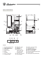
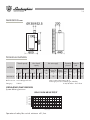
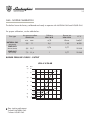
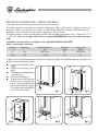
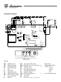
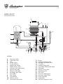
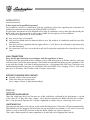
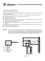
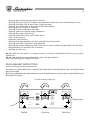
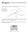
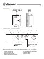
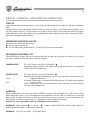
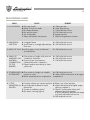
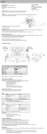
"
RE 'USO
A
N D
EG ALE
S
ON NU
I C "MA
S
T
A
EG TO TE
HA
T
PR SER TEN
R
RE
U
N
SU L” IS USE
L'I SIG.
E
AK NUA THE
AL
M
SE E MA R TO AD IO
A
E
E
ID R ”
PL “US OV
BIL SUA USO
A
E
D
M LU E
TH NDE
A ALE A AL D
A
L
H
U
AN GAR AN
G
E
M
TENENTR TO “
RO
A
E
E
L
D OL
EG ”
F
TR USO
L
N
E
E E
OR AL D TE
V
FA ANU TEN
U
“M SR.
AO
CALDAIA MURALE A GAS CON BOLLITORE AD ACCUMULO - ALTO RENDIMENTO - MODULANT
EWALL-HUNG GAS BOILER WITH HOT WATER STORAGE TANK - HIGH EFFICIENCY - MODULATING UNIT
CALDERA MURAL A GAS CON ACUMULADOR - ALTO RENDIMIENTO - MODULANTE
CALDEIRA DE PAREDE A GÁS COM TERMOACUMULADOR - ALTO RENDIMENTO - MODULANTE
MANUALE DI
INSTALLAZIONE E
MANUTENZIONE
INSTALLATION
AND MAINTENANCE
MANUAL
N 24 MB/IT
MANUAL PARA
LA INSTALACIÓN Y EL
MANTENIMIENTO
MANUAL DE
INSTALAÇÃO E
MANUTENÇÃO
ENGLISH
GB
Read carefully all warnings and instructions contained in this manual as they give
important instructions regarding safety, installation and maintenance. Keep this manual
for future reference. Installation must be carried out by qualified personnel who will
be responsible for respecting existing safety regulations.
24
INDEX
PAGE
GENERAL INSTRUCTIONS _____________________________________________
DESCRIPTION _______________________________________________________
MAIN COMPONENTS ________________________________________________
DIMENSIONS _______________________________________________________
TECHNICAL FEATURES ________________________________________________
GAS - NOZZLE CALIBRATION __________________________________________
ELECTRICAL CONNECTIONS - WIRING DIAGRAMS _______________________
MALFUNCTIONS AND ADJUSTMENTS __________________________________
WATER CONNECTION _______________________________________________
WATER CIRCUIT ______________________________________________________
INSTALLATION _______________________________________________________
START-UP ___________________________________________________________
FLUE EXHAUST CONNECTION _________________________________________
ADJUSTMENTS ______________________________________________________
SWITCHING OFF ____________________________________________________
MAINTENANCE _____________________________________________________
KNOB ASSEMBLY INSTRUCTIONS ______________________________________
OPERATION WITH DIFFERENT TYPES OF GAS ____________________________
FAULT-FINDING CHART _______________________________________________
25
26
27
28
28
29
30
32
33
34
35
35
36
37
38
38
39
41
42
Congratulations....
......on an excellent choice. We thank you for the preference accorded to our products.
LAMBORGHINI CALORECLIMA has been actively present in Italy and throughout the world
since 1959 with a widespread network of agents and concessionary agents to constantly
guarantee the presence of our product on the market.
Alongside this is the support of a technical service, “LAMBORGHINI SERVICE”, which is
entrusted with the qualified servicing of the product.
For the installation and positioning of the boiler:
CAREFULLY OBSERVE THE LOCAL REGULATIONS IN FORCE
25
GENERAL INSTRUCTIONS
●
This booklet constitutes an integral and essential part of the product.
Read carefully the instructions contained in this booklet as they provide important directions
regarding the safety of installation, use and maintenance. Preserve this booklet with care for any
further consultation. The installation of the boiler must be carried out in compliance with current
regulations, according to the instructions of the manufacturer and by qualified personnel. An
incorrect installation can cause injury or damage to persons, animals and objects, for which the
manufacturer cannot be held responsible.
●
After removing the packaging materials, check the content integrity. In case of doubt, do not use
the unit and contact the supplier. The packaging material (wooden crates, nails, clips, plastic
bags, foam, etc.) must not be left within reach of children as they are potential sources of danger.
●
This boiler is designed to heat water to a temperature below boiling (atmospheric pressure). It
must be connected to a heating system compatible with its performances and output.
●
This appliance should be destined only for the use for which it has been expressly envisaged. Any
other use is to be considered improper and therefore dangerous. The manufacturer cannot be
considered responsible for any damages caused from improper, erroneous or unreasonable use.
ALL INSTALLATION, MAINTENANCE AND GAS CONVERSION OPERATIONS MUST BE CARRIED OUT
BY AUTHORISED SKILLED TECHNICIANS.
TO ENSURE THAT BOILER IS INSTALLED CORRECTLY AND THAT IT FUNCTIONS PROPERLY, WE
RECOMMEND THAT ONLY LAMBORGHINI ACCESSORIES AND SPARE PARTS BE USED.
ON NOTICING THE SMELL OF GAS DO NOT TOUCH ANY ELECTRIC SWITCH. OPEN DOORS AND
WINDOWS. SHUT OFF THE GAS TAPS.
INSTALL THE BOILER ON WALLS WHICH ARE AS WIDE AS OR WIDER THAN THE BOILER ITSELF.
26
DESCRIPTION
These boilers are fully automatic and gas control is effected by an electronic control unit having the
following characteristics:
-
continuous modulation mode on both circuits;
possibility to adjust the heating output;
possibility to adjust the slow ignition;
“anti-Legionnaire’s” function
They are equipped with:
-
Safety flow-switch;
Total safety thermostat;
High efficiency flue gas exchanger;
60-liter tank in stainless steel for plenty of hot water
Electric 3-way valve
VELA X N 24 MB W TOP
Electronic ignition with ionisation flame control.
Combustion and fume discharge are of the atmospheric type. Fitted with FLUE CONTROL fume evacuation device.
FLUE CONTROL THERMOSTAT
VELA X N MB boilers are fitted with the FLUE CONTROL device to control evacuation of fumes. An
increase in fume temperature in the down-draught diverter indicates an anomaly in fume evacuation.
The FLUE CONTROL probe in the down-draught diverter detects variations in temperature and shuts
down the boiler. Efficient operation of this safety system depends on observance of the following:
- Do not deactivate the FLUE CONTROL thermostat.
- Inspect the boiler and the flue immediately if the FLUE CONTROL device trips frequently.
- If the FLUE CONTROL device is changed make sure you observe assembly and probe positioning
instructions carefully and use only original LAMBORGHINI spare parts.
If there is a fume evacuation anomaly act quickly to prevent the formation of Carbon Monoxide, a
poisonous gas that causes intoxication and potentially fatal harm to both humans and animals.
27
MAIN COMPONENTS
4
14
15
3
5
2
6
7
1STEP
16
8
1
13
12
21 22
11 10
23
9
17
20 19 18
LEGEND
1
2
3
4
5
6
7
8
9
Hot water expansion tank
Water-heater sensor
Heating expansion tank
Flue control
Delivery sensor
Burner
Circulator
Electric 3-way valve
Automatic by-pass
Safety flow-switch
Modulating coil
Gas valve
Hot water circuit:
- 8-bar safety valve
- Non-return valve
- Inspection filter
14 Total safety thermostat
15 Fume exchanger
10
11
12
13
16
17
18
19
20
21
22
23
Stainless steel water-heater
Thermohydrometer
Malfunction warning light
ON/OFF warning light
Lock-out warning light
Hot water adjustment potentiometer
Function selector
Heating adjustment potentiometer
28
DIMENSIONS mm
TECHNICAL FEATURES
Thermal capacity
Min. thermal
capacity
MODELL
Input
Input
Output
Output
kW kcal/h kW kcal/h kW kcal/h kW kcal/h
VELA X N 24
26 22360 23,4 20124 12,1 10406 10,43 8970
10
150
60
3
8
8
2
kg
63
Max. water temperature 90°C
Rated gas pressure: Natural gas 20 mbar
B 28/30 mbar - P 37 mbar
II 2H3+
CIRCULATING PUMP FEATURES
System delivery/pressure
VELA X N 24 MB W TOP/IT
Residual pressure mbarr
Expansion Weight
tank
Supply Peak output Water Heating Hot
Hot
first 10 heater circuit water Heating
∆ 30 °C inminutes
water
circuit
capacity max.
l
l
bar
l/min
l
l
bar
Boiler version: mod. MB type B11 BS
Category:
Operating
pressure
Hot water supply
600
500
400
300
200
100
300 400 500 600 700 800 900 1000 1100 1200 1300 1400 1500
Delivery (l/h)
Operation of safety flow switch: minimum ∆P 1,2 mt.
29
GAS - NOZZLE CALIBRATION
The boilers leave the factory calibrated and ready to operate with NATURAL GAS and LIQUID GAS.
For proper calibration, see the table below:
Gas type
NATURAL GAS
(G20-20mbar)
LIQUID GAS B
(G30-28/30mbar)
LIQUID GAS P
(G31-37mbar)
Jets pressure mbar
VELA X N 24
Delivery
Burner jets
VELA X N 24
VELA X N 24
L.C.V.
min.
max.
m3/h
Ø mm.
kcal/m3
2,5
11
2,6
1,25
8.550
5,5
23,7
0,76
0,77
29.330
7,2
31,4
1
0,77
22.360
BURNER PRESSURE CURVES - OUTPUT
VELA X N 24 MB
mbar
3,5
35
3
30
2,5
25
2
20
1,5
15
1
10
0,5
5
0,1
0
1
0
31,4
P 31,4
23,7
B 23,7
11
GN 11
7,2
5,5
1009DIS1385
kPa
2,5
0
Slow ignition adjustment
3 mbars NATURAL GAS
7 mbars LIQUID GAS
10
15
20
25
30
35
kW
30
ELECTRICAL CONNECTIONS - WIRING DIAGRAMS
The boiler must be connected to an earthed, single-phase 230V - 50 Hz mains supply by means of a
three-wire cable, ensuring that connections to the LINE and NEUTRAL terminals are made correctly.
A bipolar switch must be used with contacts opening to at least 3 mm.
The power lead must only be replaced by another with the following characteristics: “HAR H05 vv-F” 3
x 1.00 mm2. (You are strongly advised to use original LAMBORGHINI accessories and spare parts
only).
Installation must be made in compliance with safety REGULATIONS IN FORCE.
Make a good earth connection.
Voltage
V
Hz
230
50
Protection
index
Absorbed power
kW
VELA X N 24
Frequency
Noise level
dB (A)
VELA X N 24
IP
44
0,120
51
To gain access to the electrical panel which houses the power supply terminal block and any connection to a
room thermostat, proceed as follows:
●
●
●
●
●
Disconnect the boiler power
supply
Undo the two grating screws
(fig.1)
Undo the four shell attachment
screws A (fig.2)
Remove the shell (fig.3)
To gain access to the electrical
and electronic components
loosen screws B and pull the
entire panel outwards (fig.4).
Tilt it downwards and undo the
screws C on the cover D
A
fig.1
A
fig.2
D
B
C
B
fig.3
fig.4
fig.5
31
ASSEMBLY DIAGRAM
EA
VD
TST
Resist.
1 kohm
VG
Sanit.
Risc.
CiR
EC
L
F
N
RLA
TA
Timer
FC
FL
TL
JP2
Rmax
JP1
BM
X
Jumper to be cut
if limit thermostat
is required
Panel
connection
SS
SM
3
2
1
ON/OFF
warning light
Lock-out warning light
Malfunction
warning light
CONTROL PANEL
LEGEND
BM
CiR
EA
EC
F
FC
FL
JP1
JP2
L
N
Modulating coil
Heating circulator
Ignition electrode
Control electrode
Fuse
Flue control
Safety flow-switch
Methane/LPG selector
Post-circulation selector
Line 230 V 50 Hz
Neutral
RLA
Rmax.
SM
SS
TA
TL
TST
Timer
VD
VG
X
Slow ignition adjustment
Heating max. power adjustment
Delivery sensor
Hot water sensor
Room thermostat (if any)
Limit thermostat (if any)
Safety thermostat
Boiler timer adjustment
3-way valve
Gas valve
Resistor to be cut for low
1
2
3
temperatures
Heating potentiometer
Selector: Off
Summer
Winter
Reset
Test
Hot water potentiometer
32
MULFUNCTIONS AND ADJUSTMENTS
A
Constant light: Ignition
shutdown
Fast flashing light: TST
shutdown
Constant light: No water
circulation or modulating
coil
Fast flashing light:
Sensor fault
Slowly flashing light:
Flue control
Should the boiler shut down it must be reset by rotating function selector to the reset position A.
Legend:
On
Off
GPL -
JP1 On
Off
On
JP2 (post-circ. off)
heating
METHANE
Off
post-circ.
on 2.5 minutes
Resistor R150 cut, floor heating temp. set to 30/40°C.
Resistor R150 uncut, heating temperature 35/80°C
RLA
Aumento
Slow ignition adjustment
R máx
Increase
Heating power adjustment
Timer
Increase
Boiler timer adjustment
RLA Timer
Rmax
JP2
JP1
X
33
WATER CONNECTION
Fit the supporting hooks and attach the assembly template, moving it up to the wall; fit all the pipes,
starting with the end pipe fittings already mounted on the template: system supply, system return, cold
water, hot water, any gas pipes and electric mains leads with room thermostat.
Once the pipes have been fitted, the end pipe fittings can be removed and ordinary caps fitted, ready
for hydraulic tests to be carried out. The template can be removed or, if left in place, will be embedded
in the wall once finishing operations have been completed (plaster and tiles); only the two supporting
hooks will protrude from the wall, as well as an opening for the connections. Attach the boiler to the
hooks through the holes at the back of the frame and push it up against the finished wall. Make the
necessary hydraulic connections.
ADVICE AND SUGGESTIONS ON PREVENTING SYSTEM VIBRATION AND NOISE
-
Do not use pipes of reduced diameter.
Do not use low-radius elbows or fittings that significantly reduce crosssection.
Hot-flushing of the system is recommended in order to eliminate any
impurities from the piping and radiators (especially oil and grease) which
might damage the circulator.
600
476
62
62
21,5
-
GS
F
AE
M
R
GS
Hot water Ø 1/2”
Gas Ø 1/2” - Ø 3/4” (see tap
supplied with the boiler)
Boiler water supply Ø 1/2" (cold)
Electrical supply
System delivery Ø 3/4"
System return Ø 3/4"
Holding hooks Ø10 mm.
854
C
G
C
F
AE
G
R
M
24,5
NOTE: Provide female water connections.
126
226
304
382
452
522
900
LEGEND
34
WATER CIRCUIT
7
8
9
10
11
6
14
3
5
4
13
15
2
1
16
23
30
22
17
29
18
19
24
A
B
28
21 20
C
D
E
LEGEND
A
B
C
D
E
1
2
3
4
5
6
7
8
9
10
11
Hot water outlet
Cold water inlet
Gas
System return
System delivery
Magnesium anode
Water-heater sensor
Stainless steel water-heater
Ignition electrode
Detection electrode
Exchanger gas/water
Flue hood
Flue control
Thermometer
Delivery sensor
Total safety thermostat
13
14
15
16
17
18
19
20
21
22
23
24
28
29
30
Burner
Heating expansion tank
Automatic air bleed valve
Circulator
Heating safety valve
Pressostato differenziale aqua
Filling tap
Electric 3-way valve
Modulating coil
Gas valve
Pressure reading point
Hot water safety valve
Drain tap boiler
Hydrometer
Hot water expansion tank
35
INSTALLATION
To be carried out by qualified personnel.
The installation must be in compliance with the stipulations of the law regarding the evacuation of
combustion materials according to the REGULATIONS IN FORCE.
The gas fume evacuation must be effected with a pipe of a diameter not less than that required by the
boiler and it must be connected to a flue pipe suitable for the capacity of the installation.
For connection of appliances to smoke conduits:
a) they must be easy to dismantle;
b) they must be sealed and of a material able to resist the products of combustion and their possible
condensation;
c) they must not have regulation devices (gate valves). If such devices are already in operation they
must be eliminated;
d) the connection itself must not protrude inside the flue pipe but stop before the internal face of the
same.
GAS CONNECTION
Carry out the gas connection in accordance with the regulations in force.
The boiler must be connected to the installation with a rigid metal pipe or a flexible stainless steel pipe
with continuous wall of the approved type. The flexible corrugated metal pipes must be installed in such
a way that their length, in a state of maximum extension, is not greater than 2000 mm. The boilers are
calibrated and tested to function with NATURAL GAS and LIQUID GAS, category II 2H3+, with rated
pressures of 20 mbars, 28/30 mbars and 37 mbars respectively.
PUTTING THE BOILER INTO SERVICE
● Proceed with the clearing out of air.
● Check that there are no gas leaks
(use a soapy solution or equivalent product).
START-UP
REFILLING INSTALLATION
Open the supply tap slowly until the pressure of the installation, indicated by the hydrometer, is raised
to the value of 1.5 bar, then close it again. Verify that the automatic air bleed valve on the circulator
has its cap loosened. Operate the circulator repeatedly to release any air remaining in the circuit.
SWITCHING ON
Open the gas tap and turn the selector switch to the desired position. The burner will ignite automatically.
Should the burner fail to ignite check the lock-out warning light to see whether it is on, and if so turn the
selector switch to the RESET position so that the boiler repeats the ignition sequence.
Then, adjust heating and hot water temperatures as desired via the appropriate controls.
36
FLUE EXHAUST CONNECTION
The boiler is envisaged being connected to a chimney and/or a flue pipe; the combustion fumes can also be
discharged directly outside.
The joining to the chimney or flue pipe must be made with a smoke conduit having the following features:
●
●
●
●
●
●
●
●
●
of being sealed airtight, as with the connection to the chimney itself;
of being of suitable material;
of being connected within sight;
of having changes in direction, not more than 3 no., which must be carried out with internal angles
greater than 90° and with the use of curved elements;
of not having any intercepting devices;
of having the axis at the entrance of the terminal section perpendicular to the opposite internal wall of the
chimney;
of being firmly fixed and sealed at the entrance, without protruding beyond the inner walls of the chimney;
of receiving preferably one boiler only;
of observing the local regulations in force.
WARNING:
This unit is fitted with a Flue Control device to control flue draught. This is tripped when there is
a risk of combustion fume backflow. This device must never be deactivated. If combustion fumes
re-enter the room they may cause chronic or acute intoxication and can be fatal. If the Flue
Control device is changed use only original spare parts. If the device trips repeatedly check for
proper fume outflow via the chimney flue and contact a Lamborghini Service Centre.
min. 260 mm*
Flue pipe or
chimney
1000 mm
Ø 130 mm *
1009DIS55
NO
YES
* = VELA X N 24
3%
H max. 2500 mm
4
37
ADJUSTMENTS
The boilers have a fast opening gas valve. The necessary calibration for gas flow-rate may be obtained
from a double modulator coil. Calibration of the slow ignition (pre-calibrated in the factory) is
electronically done and is adjustable (for optimising and for gas type conversion) by the trimmer RLA
on the electronic board. The necessary thermal output for the heating system can be regulated by
manipulating the trimmer R MAX. All the boilers are calibrated in the factory to release 70% of their
maximum heating capacity. By manipulating the trimmer timer the waiting time for re-starting the
boiler may be varied. All adjustments must be made on the basis of the specific characteristics of the
apparatus in use. It is necessary to check the inlet and outlet pressures at the pressure plugs. After
checking, tighten the bolts properly.
ADJUSTMENT OF OUTLET PRESSURE
Maximum pressure:
● Turn the function selector to the TEST position. TEST function remains on for max. 15 minutes.
● Feed the modulating device with correct power supply.
● By turning nut B clockwise (use a 10 mm wrench), the outlet pressure increases.
Minimum pressure screw A (adjust only after the calibration of the maximum outlet pressure has been
completed):
● Disconnect modulator power supply.
● While blocking the nut B with a wrench, turn the screw A clockwise to increase the outlet pressure.
After calibration:
● Check the maximum and the minimum pressures and adjust them if necessary.
● Fit the plastic cap C.
● Rotate the function selector to the desired position.
Adjustment trimmer Timer
Adjustment trimmer RLA
C
RLA Timer
B
A
Rmax
JP2
JP1
X
Adjustment trimmer R. MAX
Note: For this calibration it is necessary to use a water column pressure gauge connected to the
pressure plug.
38
SWITCHING OFF
PROLONGED SWITCHING OFF
If the boiler should remain inactive at length close the gas tap and disconnect power supply of the
appliance.
TEMPORARY SWITCHING ON/OFF
Proceed in one of the following ways:
● use the room thermostat;
● use the adjustment potentiometers (on the instrument panel).
NOTE: with a new boiler or after a long period
of inactivity, one can check for the
locking of the circulating pump. In this
case it is necessary to unscrew the front
stopper and make the motor shaft rotate with a screwdriver.
MAINTENANCE
To ensure long-lasting product functionality and efficiency within the limits prescribed by the laws and
standards in force, the unit must undergo regular maintenance.
Frequency of inspection depends on the specific conditions of installation and use but it is advisable to
have the unit checked once a year by authorised Lamborghini Service personnel. Only properly qualified personnel with specific knowledge in the field of safety, efficiency, environmental hygiene and
combustion may carry out work on the unit. To ensure proper maintenance it is also required that such
personnel be fully updated on the constructive and functional characteristics of the boiler.
Should work or maintenance be carried out on any structures situated near fume ducts and/or fume
discharge devices and their accessories always switch off the boiler and, when work is over, have its
efficiency checked by qualified personnel
IMPORTANT: before doing any cleaning or maintenance work on the unit switch off the electrical power
supply via the switch on the boiler itself. Shut off the gas supply by closing the tap on the boiler. The
above stated work generally involves the following:
-
removal of any oxidation from burners
removal of any encrustation from heat exchangers
checking connections between the various air/fume pipes
general pipe cleaning
39
-
checking general external appearance of boiler
checking for proper ignition, shutdown and operation of both hot water and heating functions
checking for proper seal on gas/water fittings and pipes.
checking gas consumption at minimum and maximum power
checking position of ignition electrode
checking position of detection electrode
checking combustion and efficiency parameters
checking the no-gas safety device
checking combustion fumes outlet safety device
water system pressure
expansion tank efficiency
checking for proper operation of safety and adjustment thermostats
checking for proper circulation pump operation
checking that no gas whatsoever leaks from the unit and no combustion gas leaks from the downdraught diverter or the boiler-flue connection.
checking gas flow rate.
Do not clean the unit and/or its component parts with easily inflammable substances (e.g. petrol,
alcohol etc.)
Do not clean panelling, painted and plastic parts with paint diluents.
Clean the panelling with soapy water only.
KNOB ASSEMBLY INSTRUCTIONS
If the electronic display board (A) is replaced, the knobs and the control board must be correctly positioned
during reassembly.
Before reassembling the new display board, zero set the potentiometers (trimmers) by turning anticlockwise as
illustrated in the figure:
Turn the trimmers to zero set.
P1
P3
P2
J1
R1
U1
R01
R2
R3
R02
R03
Potentiometers
R4
R04
R05
(A)
LD1
Red Led
R6
R5
LD3
Green Led
LD2
Yellow Led
40
Then remove the knobs from the front panel. Screw the display board onto the back of the panel and insert the
knobs so that the arrows on the knobs are set at the minimum value (zero).
Trimmer
Enlarged detail of the correct
knob
pin
potentiometer housing
coupling as described in
the instructions above.
Knob pin
Pin housing on the
trimmer
Arrow
Knob
If a room thermostat is installed we recommend our chronothermostat CLASS PIU’ which, in addition to
guaranteeing the comfort of a precise regulation of temperature, offers a notable range of heating
programmes; alternatively use a programming digital timer.
ATTENTION. The room thermostat with 230 V mains supply must be connected to the earth terminal,
or use a class II room thermostat.
Chronothermostat CLASS PIU’ (accessory)
41
OPERATION WITH DIFFERENT TYPES OF GAS
CONVERSION FROM NATURAL GAS TO LIQUID GAS
Replace the burner jets, insert the diaphragm as illustrated in the diagram included with the relevant kit.
Shift the jumper JP1 on the modulating board from the NATURAL GAS position to the B-P position.
Then adjust properly as described in the “ADJUSTMENT” chapter on page 37.
For information on jets diameter and working gas pressure see the table below.
Gas type
Jets pressure mbar
Delivery
Burner jets
VELA X N 24
VELA X N 24
VELA X N 24
min. max.
m3/h
Ø mm.
kcal/m3
NATURAL GAS
(G20-20mbar)
LIQUID GAS B
(G30-28/30mbar)
LIQUID GAS P
(G31-37mbar)
NOx
class
L.C.V.
Gas diaphragm H
VELA X N 24
Ø
2,5
11
2,6
1,25
8.550
2
-
5,5
23,7
0,76
0,77
29.330
2
5,2
7,2
31,4
1
0,77
22.360
2
5,2
COMPONENTS FOR OPERATION ON LIQUID GAS
Gas valve
Gasket
Gas diaphragm
Gasket
H
-VI
0444 352000
BRUCIATORI
CALDAIE MURALI E TERRA A GAS
GRUPPI TERMICI IN GHISA E IN ACCIAIO
GENERATORI DI ARIA CALDA
TRATTAMENTO ACQUA
CONDIZIONAMENTO
Le illustrazioni e i dati riportati sono indicativi e non impegnano. La LAMBORGHINI si riserva il diritto di apportare senza
obbligo di preavviso tutte le modifiche che ritiene più opportuno per l'evoluzione del prodotto.
The illustrations and details reported are indicative only and are not binding. LAMBORGHINI reserves the right to introduce alterations
and/or amendmentsas it deems fit and proper for the development of the product without the obligation of providing prior notice.
Las ilustraciones y los datos son indicativos y no comprometen. LAMBORGHINI se reserva el derecho de realizar
sin preaviso todas las modificaciones que estime oportuno para la evolución del producto.
As ilustrações e os dados existentes são indicativos e não vinculatórios. A LAMBORGHINI reserva-se o direito de efectuar, sem a
obrigação de pré-aviso, todas as modificações que considerar necessárias para a melhoria do produto.
LAMBORGHINI CALOR S.p.A.
VIA STATALE, 342
44040 DOSSO (FERRARA)
ITALIA
TEL. ITALIA 0532/359811 - EXPORT 0532/359913
FAX ITALIA 0532/359952 - EXPORT 0532/359947
Cod. 97.50612.0/2 09/2004
IT
CALDAIA MURALE A GAS CON BOLLITORE AD ACCUMULO
ALTO RENDIMENTO - MODULANTE
MANUALE PER L'UTENTE
GB
WALL-HUNG GAS BOILER WITH HOT WATER STORAGE
TANK - HIGH EFFICIENCY - MODULATING UNIT
USER MANUAL
ES
CALDERA MURAL A GAS CON ACUMULADOR
ALTO RENDIMIENTO - MODULANTE
MANUAL PARA EL USUARIO
PT
CALDEIRA DE PAREDE A GÁS COM TERMOACUMULADOR ALTO RENDIMENTO - MODULANTE
MANUAL DO UTENTE
2
Alla cortese attenzione del sig. INSTALLATORE:
Consegnare il presente manuale d'uso all'UTENTE
9
For the attention of the INSTALLATION TECHNICIAN:
Make sure that this manual is handed over to the USER
16
A la atención del Sr. INSTALADOR:
Entregar el presente manual para el uso al USUARIO
23
À atenção do Sr. INSTALADOR:
Entregue este manual de uso ao UTENTE
N 24 MB/IT
9
INDEX
PAGE
GENERAL INSTRUCTIONS ____________________________________________
INSTRUCTIONS FOR THE USE _________________________________________
CHECKS AND MAINTENANCE _______________________________________
DIMENSIONS _______________________________________________________
START UP - OPERATION - SWITCHING OFF INSTRUCTIONS ______________
FAULT-FINDING CHART ______________________________________________
10
11
12
13
14
15
Dear User...
.......you have entered into possession of a product that is the result of a careful design and
advanced production systems ensuring high-top operational reliability and saving. Read carefully
this guide in order to know any detail concerning the product’s operation system.
The “LAMBORGHINI SERVICE” after-sales centres are at your disposal to ensure QUALIFIED
MAINTENANCE and PROMPT SERVICE.
LAMBORGHINI CALORECLIMA
For the installation and positioning of the boiler
CAREFULLY OBSERVE THE LOCAL REGULATIONS IN FORCE
10
GENERAL INSTRUCTIONS
● This booklet constitutes an integral and essential part of the product and should be preserved for any
further consultation.
Read carefully the instructions contained in this booklet as they provide important directions regarding the
operation of the appliance, allowing a great saving in its use and maintenance.
● If the appliance is sold or transferred to other people or if you move house and leave your apartment,
ensure that the manual remains with the appliance so that it can be used by the new owner.
● This appliance should be destined only for the use for which it has been expressly envisaged. Any other
use is to be considered improper and therefore dangerous. The manufacturer cannot be considered
responsible for any damages caused from improper or unreasonable use.
● Do not touch the parts of the boiler which during the operation become overheated. These parts can be
dangerous for children or inexperienced persons.
● Do not obstruct the inlet or dissipation screens.
● Do not make the boiler wet with splashes of water or other liquids.
● Do not rest any object upon the boiler.
● Use of the boiler is prohibited for children or the inexperienced.
● Do not carry out any cleaning of the boiler with inflammable substances.
● Do not deposit containers of inflammable substances in the location where the boiler is situated.
● In the presence of the risk of freezing suitable provisions must be taken which are not however the concern
of the boiler manufacturer.
ALL INSTALLATION, MAINTENANCE AND GAS CONVERSION OPERATIONS MUST BE CARRIED OUT BY
AUTHORISED SKILLED TECHNICIANS.
TO ENSURE THAT BOILER IS INSTALLED CORRECTLY AND THAT IT FUNCTIONS PROPERLY, WE RECOMMEND
THAT ONLY LAMBORGHINI ACCESSORIES AND SPARE PARTS BE USED.
ON NOTICING THE SMELL OF GAS DO NOT TOUCH ANY ELECTRIC SWITCH. OPEN DOORS AND WINDOWS.
SHUT OFF THE GAS TAPS.
11
INSTRUCTIONS FOR THE USE
● In case of breakdown and/or malfunctioning of the appliance, disconnect it avoiding any attempt of
repair or direct intervention.
Call exclusively professionally qualified personnel.
Any repair must be carried out by an after-sale service centre “LAMBORGHINI SERVICE” authorised by
the manufacturing firm, and using original replacements exclusively.
Non-observance of the above could compromise the safety of the appliance.
In order to guarantee the efficiency of the appliance and its proper operation it is indispensible to keep to
the manufacturer’s directions, by ensuring the periodical servicing of the appliance is carried out by
professionally qualified personnel.
● Check the system hydraulic pressure during the first ignition and then periodically by using the hydrometer.
Check that readings for the system when cold are within manufacturer-specified limits. Should any falls-off
in pressure be noticed contact a qualified technician.
● After each reopening of the gas tap wait a few minutes before restarting the boiler.
● Do not leave the boiler switched on if it is not used for long time: in this case switch gas main supply,
electricity and water supply off by their own taps and switches.
● As soon as one decides not to use the appliance further, one should take care to render innocuous those
parts liable to be potential sources of danger.
● As soon as one decides to disconnect the boiler definitively, one should ask qualified personnel to effect
the related works, then ensure that the main supplies have been disconnected.
● For the power supply to the boiler the use of adaptors, multiple sockets or extensions is not permitted.The
use of a switch as indicated by the safety regulations in force must be provided.
● The use of appliances which utilise electrical energy involve the observation of fundamental rules which
are:
a)
b)
c)
d)
not to touch the appliance with parts of the body which are wet or when in bare feet;
not to pull electrical wires;
not to expose the appliance to the atmospheric agents;
not to allow use of the appliance to children or the inexperienced.
● In the case of structural work positioned near the flue pipe, turn off the boiler and at the end of the work
ensure that the efficiency of the flue exhaust is verified by qualified personnel.
● On noticing the smell of gas do not touch any electric switch.Open all doors and windows. Shut off the gas
taps and call qualified personnel.
12
CHECKS AND MAINTENANCE
● Before starting up the boiler ask qualified personnel “LAMBORGHINI SERVICE” to check:
a) that the data on the information plate corresponds to that required by the gas, electrical and water
supply networks;
b) that the pipes which branch off from the boiler are lined with suitable thermally-insulated sheathing;
c) the proper functioning of the flue pipe;
d) that the comburent air flow and the fumes evacuation take place properly in accordance with the
regulations in force;
e) that correct aeration and maintenance are possible in case of installation in the furniture.
● The conversion from a gas (methane or B/P) to a gas of another family, which can also be made with the
boiler installed, must be made exclusively by qualified personnel.
● Ensure that the installer has connected the boiler and water-heater safety discharge to a waste. In the case
of the contrary the intervention of the safety valves could flood the premises. The manufacturer would not
be held responsible for this.
● Ensure that the piping of the installation is not used as an earth outlet for other installations; beyond not
being ideal for such a use it could in short bring serious damage to the other appliances connected to it.
● Ask qualified personnel “LAMBORGHINI SERVICE” to check:
a)
b)
c)
d)
e)
the internal and external tightness of the gas system;
that the gas delivery is that required by the boiler output;
that the type of gas is suitable for the boiler;
that the pressure of gas supply is within the values stated on the boiler plate;
that the gas installation is the correct size and equipped with all the safety and checking devices
prescribed by the current regulations.
● Ask periodically to check the proper functioning and the good state of the flue exhaust.
● Ensure that the electrical system has been confirmed by qualified personnel to be adequate for the power
required by the appliance itself.
● The electricity supply cable must not be replaced by the user, but by qualified personnel only.
● The electrical safety of the appliance is attained only if the same has been connected to an effective system
earthed in accordance with the current regulations. The verification of this fundamental prerequisite should
be made by qualified persons as the manufacturer will not be responsible for damage caused by the lack
of adequate earthing of the installation.
13
DIMENSIONS mm.
CONTROL PANEL AND MULFUNCTIONS
1
5
2
6
4
3
7
A
Constant light: Ignition
shutdown
Constant light: No water
circulation or modulating coil
Fast flashing light: TST
shutdown
Fast flashing light: Sensor
fault
Slowly flashing light: Flue
control
Should the boiler shut down it must be reset by rotating function selector 6 to the reset position A.
1
2
3
4
Lock-out warning light
ON/OFF warning light
Malfunction warning light
Heating adjustment potentiometer
5
6
7
Hot water adjustment potentiometer
Operation selector
Thermohydrometer
14
START UP - OPERATION - SWITCHING OFF INSTRUCTIONS
START UP
Open the gas tap and tun the selector switch (6) to the desired position. the burner will ignite automatically.
Should ignition fail to take place check the lock-out warning lights (1) and fault warning lights (3) to
see if they have come on. Turn the selector (6) to the reset position A. Then rotate the selector (6) again
to the desired position. Then adjust heating temperature (4) and domestic hot water temperature (5) as
desired via the appropriate controls.
TEMPORARY SWITCHING ON/OFF
Proceed in one of the following ways:
● use the room thermostat;
● use the adjustment potentiometers, (4) and (5) on the instrument panel.
PROLONGED SWITCHING OFF
Should the boiler remain idle for a long period close the gas tap, position the selector switch (6) at
position 0 and disconnect the electrical power supply.
SUMMER MODE:
Turn the selector switch (6) to SUMMER.
Regulate the domestic hot water potentiometer (5) to a position corresponding
to desired water temperature.
WINTER MODE:
Turn the selector switch (6) to WINTER.
Regulate the Heating Potentiometer (4) to a position that corresponds to deheating temperature.
If a Room Thermostat is installed then the thermostat will keep room temperaat the set level.
Adjust the domestic hot water potentiometer (5) to a position corresponding to
desired water temperature.
sired
ture
IMPORTANT:
VELA X MB boilers are fitted with FLUE CONTROL to monitor flue draught. This safety device shuts
down the boiler if there is a risk of combustion fume backflow into the room. This device must never be
deactivated. If combustion fumes re-enter the room they may cause chronic or acute intoxication that
can be fatal. If the Flue Control device is changed use only original spare parts.
If the device trips repeatedly contact a Lamborghini Service Centre.
WARNING: When Summer
or Winter
mode is selected the ON indicator light comes on
indicating that the boiler is electrically powered.
WARNING: Use only 2A/250V - 5x20 rapid fuses.
15
FAULT-FINDING CHART
FAULT
CAUSE
REMEDY
1 NO IGNITION
A.Gas tap closed
B. Boiler in lock-out mode
C. No flame detection
D.No ignition spark
E. Air inside pipes
F. Safety thermostat intervention
A. Open gas tap
B. Reset by pressing
C. Call technical service
D. Call technical service
E. Repeat ignition
F. Wait for temperature to lower
2 CRACKLING
IGNITION
A. Irregular flame
B. Insufficient or wrongly adjusted gas
flow-rate
A. Call technical service
B. Call technical service
3 SMELL OF GAS A.Leak in pipes circuit (inside and
outside boiler)
A. Call technical service
A.Flue section or height with joint not
4 SMELL OF
suitable for the boiler
UNBURNT GAS
B. Excessive gas consumption AND BAD
COMBUSTION
Combustion state is imperfect
C. Flames tend to move away or have
OF THE
yellow tips
BURNER
A. Call technical service
B. Call technical service
C. Call technical service
5 CONDENSATION A.Flue section or height not suitable
(excessive size)
IN THE BOILER
B. Boiler operating at low temperature
A. Call technical service
B. Adjust boiler thermostat at a higher
temperature.
A.Function selector on summer position A.Place it on winter position
6 COLD
B. Adjust thermostat at a higher tempe
RADIATORS IN B. Low adjusted or defective room
thermostat
rature or replace it.
WINTER
C. System or radiators closed
C. Check if system gate valves and
D.No water warning light on
radiators taps are opened.
If item C has been checked with nega
tive result call technical service
D.Call technical service
Le illustrazioni e i dati riportati sono indicativi e non impegnano. La LAMBORGHINI si riserva il diritto di apportare senza
obbligo di preavviso tutte le modifiche che ritiene più opportuno per l'evoluzione del prodotto.
The illustrations and details reported are indicative only and are not binding. LAMBORGHINI reserves the right to introduce alterations
and/or amendments as it deems fit and proper for the development of the product without the obligation of providing prior notice.
Las ilustraciones y los datos son indicativos y no comprometen. LAMBORGHINI se reserva el derecho de realizar sin preaviso
todas las modificaciones que estime oportuno para la evolución del producto.
As ilustrações e os dados existentes são indicativos e não vinculatórios. A LAMBORGHINI reserva-se o direito de efectuar, sem
a obrigação de pré-aviso, todas as modificações que considerar necessárias para a melhoria do produto.
LAMBORGHINI CALOR S.p.A.
VIA STATALE, 342
44040 DOSSO (FERRARA)
ITALIA
TEL. ITALIA 0532/359811 - EXPORT 0532/359913
FAX ITALIA 0532/359952 - EXPORT 0532/359947
Cod. 97.50612.0/2 09/2004
-VI
0444 352000
BRUCIATORI
CALDAIE MURALI E TERRA A GAS
GRUPPI TERMICI IN GHISA E IN ACCIAIO
GENERATORI DI ARIA CALDA
TRATTAMENTO ACQUA
CONDIZIONAMENTO