1
SAG586505000
SAG586505500
System Application Guide
Spec. No. 586505000 (Model LMS1000)
Spec. No. 586505500 (Model LMS1000)
Issue AU, May 10, 2010
Home
SYSTEM OVERVIEW
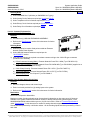
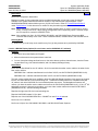
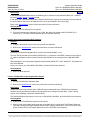
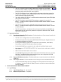
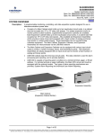
Description:
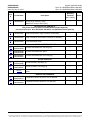
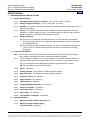
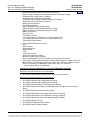
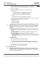
A programmable monitoring, controlling, and data acquisition system designed for use in
telecommunications power sites.
•
Consists of a Main Cabinet which holds up to ten input/output circuit cards, in a cabinet
size that occupies two 19" or 23" relay rack spaces. For system expansion and/or to
monitor points at other locations, Supplemental (Expansion) Cabinets are available.
Each Expansion Cabinet holds up to ten input/output circuit cards, in a cabinet size that
occupies two 19" or 23" relay rack spaces. Also available are Expansion Assemblies
which provide an input circuit card equipped with a fixed number of analog and binary
input points in a sheet metal housing. These assemblies can be mounted inside
customer equipment. The Main Cabinet, Expansion Cabinets, and Expansion
Assemblies are interconnected via the LMS1000 network.
•
The Main Cabinet and Expansion Cabinets can be equipped with various input circuit
cards to monitor a variety of analog, binary, and temperature points. The Expansion
Assemblies are always equipped with an input circuit card to monitor a fixed number of
analog and binary points.
•
LMS1000 collects data from the input circuit cards. The data collected is used for alarm
processing and reporting, and to provide statistics.
•
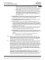
LMS1000 is capable of reporting alarm conditions to a remote terminal, pager, or Email
address. For remote terminal or pager notification, the Main CPU circuit card must be
equipped with the optional modem. Two types of alarm reporting mechanisms are
provided, System Alarm Reporting and Individual User Alarm Reporting.
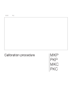
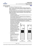
Expansion Assembly
Main Cabinet
(Expansion Cabinet Similar)
Page 1 of 69
This document is property of Emerson Network Power, Energy Systems, North America, Inc. and contains confidential and proprietary information owned by Emerson Network Power, Energy
Systems, North America, Inc. Any copying, use, or disclosure of it without the written permission of Emerson Network Power, Energy Systems, North America, Inc. is strictly prohibited.
SAG586505000
SAG586505500
Issue AU, May 10, 2010
System Application Guide
Spec. No. 586505000 (Model LMS1000)
Spec. No. 586505500 (Model LMS1000)
Home
•
LMS1000 is capable of reporting alarm conditions via SNMP traps over
Ethernet, or via TL1 (over Ethernet) when the 'TL1 over Ethernet' option is
ordered. TL1 is also available via a serial connection in 'direct mode'.
•
The Main CPU circuit card provides programmable LEDs to allow local indication of alarm
conditions or occurrences. For remote indication, the Main and/or Expansion Cabinets
can be equipped with output circuit cards which provide programmable relays. These
relays may also be used to control other equipment.
•
LMS1000 easily interfaces with the MCA of Vortex® Power Systems (VPS) and
NETSURE™ Power Systems (NPS). This interface allows an LMS1000 user to remotely
monitor, adjust, and control the Power System via LMS1000; plus easily use the features
of LMS1000 with the Power System. Separate analog, binary, and relay circuit cards do
not have to be supplied for this interface. Analog, binary, relay, and temperature circuit
cards (I/O cards) can be provided to monitor equipment external to the Power System. In
a VPS/NPS, one simple cable connection between the Main Cabinet and the VPS/NPS
completes the interconnections required. Note that the LMS1000 is factory integrated
into Spec. Nos. 582140000, 582140001, and 582126100 NETSURE Power Systems.
Note that Spec. Nos. 582140000, 582140001, and 582126100 NETSURE Power
Systems do not use the LMS1000 Cabinets. The LMS1000 is factory integrated into
the Power Systems. Note that LMS1000 I/O circuit card mounting positions are
provided inside a 582140000, 582140001, and 582126100 NETSURE Power System.
•
LMS1000 can be accessed via a local port, a modem port (when optional modem is
ordered), an optional TL1 port, and an Ethernet port (for Telnet access, Web access,
SNMP access, optional TL1 access, and Email alarm reporting). A local front panel
display option is also available.
•
Available software options include…
Power Metering
Energy Management*
Rectifier/PCU Sequencing*
TL1/X.25
TL1 (over Ethernet)
Gateway Port
LMS Dual MCA Interface
* Note: LMS1000 Energy Management and Sequencing features are not for use in the
Spec. Nos. 582140000, 582140001, and 582126100 Power Systems.
•
Available specialty interfaces include…
Door Access Controller Interface
External GPS Modem Interface
AC Analyzer Interface
Page 2 of 69
This document is property of Emerson Network Power, Energy Systems, North America, Inc. and contains confidential and proprietary information owned by Emerson Network Power, Energy
Systems, North America, Inc. Any copying, use, or disclosure of it without the written permission of Emerson Network Power, Energy Systems, North America, Inc. is strictly prohibited.
System Application Guide
Spec. No. 586505000 (Model LMS1000)
Spec. No. 586505500 (Model LMS1000)
SAG586505000
SAG586505500
Issue AU, May 10, 2010
Home
Family:
LMS Series
Spec. No.:
586505000 and 586505500
Model:
LMS1000
Agency Approval:
UL Recognized to UL 1950
CSA 22.2, No. 950
Framework Type:
Main and Expansion Cabinets: Mounted in a Customer Provided 19
or 23 Inch Wide Rack
Mounting Width:
Main and Expansion Cabinets: 19 or 23 Inch (Relay Rack Mounting)
Mounting Depth:
Main and Expansion Cabinets: 13.250 Inches
Mounting Height:
Main and Expansion Cabinets: 3.470 Inches
Access:
Front and Rear for Installation and Maintenance, Front for Operation
Color:
586505000: Off-White (Lorain Spec. M500-117)
586505500: Textured Gray (Lorain Spec. M500-147)
Options:
Main Cabinet - 19"/23", Main Cabinet - 23" only, Expansion Cabinets
- 19"/23", Expansion Cabinets - 23" only, Expansion Assemblies, (4)
Input Analog Card, (8) Input Temperature Card, (8) Input Analog
Card, (12) Input Analog Card for Measuring Individual Battery Cell
Voltages, (4) Input Binary Card, (8) Input Binary Card, (4) Output
Form-C Relay Card, Front Panel Display Option for 19" Cabinets
(later version cabinets), Front Panel Display Option for 19" Cabinets
(earlier version cabinets), Front Panel Display Option for 23"
Cabinets (requires 10th I/O slot), Front Panel Display Option for 23"
Cabinets (DOES NOT require 10th I/O slot), Modem, LMS Dual MCA
Interface Software Option, Gateway Port Software Option, Door
Access Controller Interface, PCU/Rectifier Sequencing Software
Option, Energy Management Software Option, External GPS Modem
Interface, AC Analyzer Interface, TL1/X.25 Software Option, Power
Metering Software Option, Local Port Redirection Option, TL1 (over
Ethernet) Software Option, MCA Interface Cable Options, Current
Limit Resistor Kits, In-Line Fuse Kits, Temperature Sensors
Accessories:
In-Line Fuse Kit, Replacement CPU Memory Backup Battery,
LMS1000 Network Cable Options, 130VDC Monitoring Wire Harness
Environment:
-40°C to +60°C (-40°F to +140°F)
Page 3 of 69
This document is property of Emerson Network Power, Energy Systems, North America, Inc. and contains confidential and proprietary information owned by Emerson Network Power, Energy
Systems, North America, Inc. Any copying, use, or disclosure of it without the written permission of Emerson Network Power, Energy Systems, North America, Inc. is strictly prohibited.
SAG586505000
SAG586505500
Issue AU, May 10, 2010
System Application Guide
Spec. No. 586505000 (Model LMS1000)
Spec. No. 586505500 (Model LMS1000)
Home
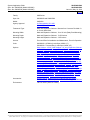
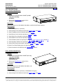
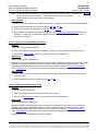
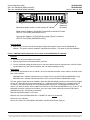
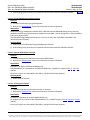
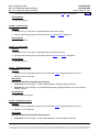
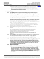
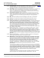
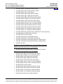
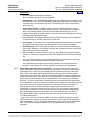
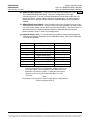
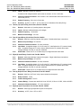
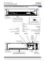
586505000 and 586505500
Main Cabinet
(Expansion
Cabinets
Similar)
(19" Cabinet
Shown)
List 1: LMS1000 Monitoring System
(MAIN CABINET - 19"/23")
List 2: LMS1000 Monitoring System
(MAIN CABINET - 23" only)
List 6: LMS1000 Monitoring System
(EXPANSION CABINETS - 19"/23")
List 7: LMS1000 Monitoring System
(EXPANSION CABINETS - 23" only)
List 10: LMS1000 Monitoring System
(EXPANSION ASSEMBLIES) (not shown)
P/O List 1 and 6: CPU Circuit Card
List 70: Modem Circuit Card
(MAIN CABINET ONLY)
List 92: VPS MCA Interface Cable,
Customer Specified Length
List 93: VPS MCA Interface Cable
Termination Kit
List 94: VPS MCA Interface Cable,
Pre-Assembled, 6'
Standard Software Features
Available Specialty Interfaces
WEB Interface Software Feature
List 80: Door Access Controller
Interface
SNMP Software Feature
Available Software Options
List 78: LMS Dual MCA Interface
Software Option
List 79: Gateway Port Software Option
List 82: PCU/Rectifier Sequencing
Software Option
List 83: Energy Management Software Option
List 86: TL1/X.25 Software Option
List 87: Power Metering Software Option
List 88: Local Port Redirection
List 90: TL1 (over Ethernet) Software Option
List 84: External GPS Modem
Interface
Front Door
Opened in
Illustration
Determines
Earlier vs. Later
Version 19" Cabinets
List 85: AC Analyzer Interface
Front Panel Display Option
List 60: (for use in later
version 19" cabinets)
List 61: (for use in earlier
version 19" cabinets)
List 62: (for use in 23" cabinets)
(requires 10th I/O slot)
I/O Slot #10 has a
Larger (30 pos.)
Connector
I/O Slot #10 is the
Same as the Other I/O
Slots
List 63: (for use in 23" cabinets)
(DOES NOT require 10th
I/O slot)
Page 4 of 69
This document is property of Emerson Network Power, Energy Systems, North America, Inc. and contains confidential and proprietary information owned by Emerson Network Power, Energy
Systems, North America, Inc. Any copying, use, or disclosure of it without the written permission of Emerson Network Power, Energy Systems, North America, Inc. is strictly prohibited.
System Application Guide
Spec. No. 586505000 (Model LMS1000)
Spec. No. 586505500 (Model LMS1000)
SAG586505000
SAG586505500
Issue AU, May 10, 2010
Home
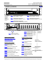
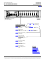
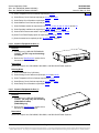
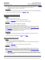
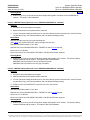
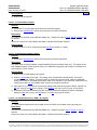
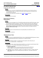
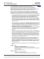
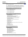
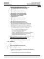
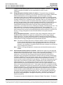
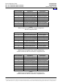
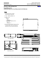
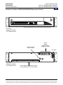
Main Cabinet
(Expansion Cabinets Similar)
(19" Cabinet Shown)
Front Door
Opened in
Illustration
Available Input/Output (I/O)
Circuit Cards
List BA, BB, and BC: Current Limit
Resistor Kits
List 20: Four (4) Input Analog
Circuit Card
List BE, BF,
and P/N 535135:
List 21: Eight (8) Input
Temperature Circuit
Card
List ST and SU: Temperature
Sensors
In-Line Fuse
Kits
List 22: Eight (8) Input Analog
Circuit Card
List 23: Twelve (12) Input
Analog Circuit Card
for Measuring
Individual Battery Cell
Voltages
List 30: Four (4) Input Binary
Circuit Card
List 31: Eight (8) Input Binary
Circuit Card
List 40: Four (4) Output
Form-C Relay Circuit
Card
SEE ALSO
System Overview
Table of Contents
List Structure Table
Accessories
Specifications
Dimensional Drawings
Related Documentation
Page 5 of 69
This document is property of Emerson Network Power, Energy Systems, North America, Inc. and contains confidential and proprietary information owned by Emerson Network Power, Energy
Systems, North America, Inc. Any copying, use, or disclosure of it without the written permission of Emerson Network Power, Energy Systems, North America, Inc. is strictly prohibited.
System Application Guide
Spec. No. 586505000 (Model LMS1000)
Spec. No. 586505500 (Model LMS1000)
SAG586505000
SAG586505500
Issue AU, May 10, 2010
TABLE OF CONTENTS
Ordering Information
System
Overview
Picture
List
Descriptions
Accessory
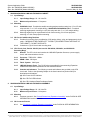
Descriptions
Specifications
Physical Size
Information
Related
Documentation
SYSTEM OVERVIEW.................................................................................................................................................1
TABLE OF CONTENTS.............................................................................................................................................6
ORDERING INFORMATION......................................................................................................................................8
List Options..........................................................................................................................................................8
Accessory Options............................................................................................................................................11
LIST DESCRIPTIONS ..............................................................................................................................................12
List 1: Common Equipment for the LMS1000 Main Cabinet.........................................................................12
List 2: Common Equipment for the LMS1000 Main Cabinet.........................................................................12
List 6: Common Equipment for One (1) LMS1000 Expansion Cabinet ........................................................13
List 7: Common Equipment for One (1) LMS1000 Expansion Cabinet ........................................................13
List 10: Common Equipment for One (1) LMS1000 Expansion Assembly ...................................................14
List 20: Four (4) Input Analog Circuit Card ...................................................................................................14
List 21: Eight (8) Input Temperature Circuit Card .........................................................................................15
List 22: Eight (8) Input Analog Circuit Card...................................................................................................15
List 23: Twelve (12) Input Analog Circuit Card for Measuring Individual Battery Cell Voltages ....................16
List 30: Four (4) Input Binary Circuit Card ....................................................................................................16
List 31: Eight (8) Input Binary Circuit Card....................................................................................................17
List 40: Four (4) Output Form-C Relay Circuit Card .....................................................................................17
List 60: LMS1000 Display Option (for use in later version 586505000 19" cabinets)...................................18
List 61: LMS1000 Display Option (for use in earlier version 586505000 19" cabinets)................................19
List 62: LMS1000 Display Option (for use in 586505000/586505500 23" cabinets) ....................................20
List 63: LMS1000 Display Option (for use in 586505000/586505500 23" cabinets) ....................................20
List 70: Modem Circuit Card..........................................................................................................................21
List 78: LMS Dual MCA Interface Software Option.......................................................................................21
List 79: Gateway Port Software Option.........................................................................................................21
List 80: Door Access Controller (DAC) Interface ..........................................................................................22
List 82: PCU/Rectifier Sequencing Software Option.....................................................................................22
List 83: Energy Management Software Option .............................................................................................23
List 84: External GPS Modem Interface........................................................................................................23
List 85: AC Analyzer Interface.......................................................................................................................23
List 86: TL1/X.25 Software Option ................................................................................................................24
List 87: Power Metering Software Option .....................................................................................................24
List 88: Local Port Redirection to OEM 1 Port Option...................................................................................24
List 90: TL1 (over Ethernet) Software Option ...............................................................................................25
List 92: MCA Interface Cable, Customer Specified Length ..........................................................................25
List 93: MCA Interface Cable Termination Kit...............................................................................................25
List 94: MCA Interface Cable, Pre-assembled..............................................................................................26
List BA: Current Limit Resistor Kit.................................................................................................................26
List BB: Current Limit Resistor Kit.................................................................................................................26
List BC: Current Limit Resistor Kit.................................................................................................................26
List BE: In-Line Fuse Kit................................................................................................................................27
List BF: In-Line Fuse Kit................................................................................................................................27
List ST: Temperature Sensor ........................................................................................................................27
List SU: Temperature Sensor........................................................................................................................27
Page 6 of 69
This document is property of Emerson Network Power, Energy Systems, North America, Inc. and contains confidential and proprietary information owned by Emerson Network Power, Energy
Systems, North America, Inc. Any copying, use, or disclosure of it without the written permission of Emerson Network Power, Energy Systems, North America, Inc. is strictly prohibited.
System Application Guide
Spec. No. 586505000 (Model LMS1000)
Spec. No. 586505500 (Model LMS1000)
SAG586505000
SAG586505500
Issue AU, May 10, 2010
ACCESSORY DESCRIPTIONS...............................................................................................................................29
In-Line Fuse Kit, P/N 535135 ............................................................................................................................29
Replacement CPU Memory Backup Battery ...................................................................................................29
LMS1000 Network Cables.................................................................................................................................29
130VDC Monitoring Wire Harness ...................................................................................................................30
SPECIFICATIONS....................................................................................................................................................31
1. 586505000/586505500 LMS1000 System ....................................................................................................31
1.1 Environmental Ratings .............................................................................................................................31
1.2 Firmware Specifications ...........................................................................................................................31
1.3 Node Specifications..................................................................................................................................31
1.4 Software Features ....................................................................................................................................32
1.5 Standard Software Features ....................................................................................................................42
1.6 Available Software Options ......................................................................................................................43
1.7 Specialty Interfaces ..................................................................................................................................48
2. 586505000/586505500 LMS1000 Main Cabinet...........................................................................................48
2.1 Input Ratings ............................................................................................................................................48
2.2 Mounting...................................................................................................................................................49
2.3 I/O Circuit Card Mounting Positions .........................................................................................................49
2.4 CPU Circuit Card, Part No. 545476 (used in 586505000/586505500) and 545558 (used in
582140000, 582140001, and 582126100).....................................................................................................49
2.5 LMS1000 Front Panel Display Option......................................................................................................52
2.6 Optional Modem Circuit Card, Part No. 508951.......................................................................................53
3. 586505000/586505500 LMS1000 Expansion Cabinet.................................................................................57
3.1 Input Ratings ............................................................................................................................................57
3.2 Mounting...................................................................................................................................................57
3.3 I/O Circuit Card Mounting Positions .........................................................................................................57
3.4 CPU Circuit Card, Part No. 506153 (also used in 582140000, 582140001, and 582126100
Secondary Bays) ............................................................................................................................................57
4. 586505000/586505500 LMS1000 Expansion Assembly.............................................................................57
4.1 Input Ratings ............................................................................................................................................57
4.2 Mounting...................................................................................................................................................57
4.3 I/O Connector Pinouts ..............................................................................................................................57
4.4 CPU Circuit, P/O Part No. 507606 ...........................................................................................................58
5. Input/Output (I/O) Circuit Cards ..................................................................................................................58
5.1 Four (4) Input Analog Circuit Card, Part No. 506336...............................................................................58
5.2 Eight (8) Input Analog Circuit Card, Part No. 514528 ..............................................................................58
5.3 Twelve (12) Input Analog Circuit Card, Part No. 520838.........................................................................59
5.4 Four (4) Input Binary Circuit Card, Part No. 506332................................................................................59
5.5 Eight (8) Input Binary Circuit Card, Part No. 506334 ...............................................................................59
5.6 Four (4) Output Form-C Relay Circuit Card, Part No. 506335.................................................................59
5.7 Eight (8) Input Temperature Circuit Card, Part No. 506333.....................................................................59
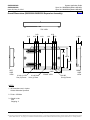
PHYSICAL SIZE INFORMATION ............................................................................................................................60
Overall Dimensions (586505000 Main [List 1] and Expansion [List 6] Cabinets) .......................................60
Overall Dimensions (586505000/586505500 Main [List 2] and Expansion [List 7] Cabinets) ....................61
Overall Dimensions (586505000/586505500 Expansion Assembly).............................................................62
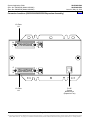
Connector Locations (586505000/586505500 Main Cabinet) ........................................................................63
Connector Locations (586505000/586505500 Expansion Cabinet) ..............................................................64
Connector Locations (586505000/586505500 Expansion Assembly) ..........................................................65
RELATED DOCUMENTATION................................................................................................................................68
REVISION RECORD ................................................................................................................................................69
Page 7 of 69
This document is property of Emerson Network Power, Energy Systems, North America, Inc. and contains confidential and proprietary information owned by Emerson Network Power, Energy
Systems, North America, Inc. Any copying, use, or disclosure of it without the written permission of Emerson Network Power, Energy Systems, North America, Inc. is strictly prohibited.
System Application Guide
Spec. No. 586505000 (Model LMS1000)
Spec. No. 586505500 (Model LMS1000)
SAG586505000
SAG586505500
Issue AU, May 10, 2010
Home
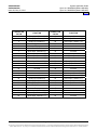
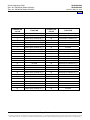
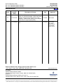
ORDERING INFORMATION
List Options
Order the following by the items Part Number as specified in the following table.
When viewing electronically, click on the link to jump to the detailed description page.
List
#
Part Number
Description
Mounting
Positions
Notes
(1U = 1-3/4")
COMMON EQUIPMENT
1
58650500001
2
58650500002
58650550002
6
58650500006
7
58650500007
58650550007
10
58650500010
58650550010
Common Equipment for the LMS1000 MAIN CABINET,
includes …
Main Cabinet - 19"/23" (off-white)
Main Cabinet CPU Circuit Card
Common Equipment for the LMS1000 MAIN CABINET,
includes …
Main Cabinet - 23" only (586505000 off-white)
23" only (586505500 gray)
Main Cabinet CPU Circuit Card
Common Equipment for One (1) LMS1000 EXPANSION
CABINET, includes …
Expansion Cabinet - 19"/23" (off-white)
Expansion Cabinet CPU Circuit Card
Common Equipment for One (1) LMS1000 EXPANSION
CABINET, includes …
Expansion Cabinet - 23" only (586505000 off-white)
23" only (586505500 gray)
Expansion Cabinet CPU Circuit Card
Common Equipment for One (1) LMS1000 EXPANSION
ASSEMBLY, includes …
CPU/Input Circuit Card
Sheet Metal Covering
2U
--
2U
--
2U
--
2U
--
--
--
Four (4) Input Analog Circuit Card
--
--
Eight (8) Input Temperature Circuit Card
--
--
Eight (8) Input Analog Circuit Card
--
--
INPUT/OUTPUT (I/O) CIRCUIT CARDS
(for use in List 1, 2, 6, and 7 cabinets, and the Spec. Nos.
582140000, 582140001, and 582126100 Power Systems)
20
21
22
58650500020
58650550020
58650500021
58650550021
58650500022
58650550022
23
58650500023
58650550023
Twelve (12) Input Analog Circuit Card for Measuring
Individual Battery Cell Voltages (not for use in a List 6 and
7 cabinets)
--
--
30
58650500030
58650550030
Four (4) Input Binary Circuit Card
--
--
Page 8 of 69
This document is property of Emerson Network Power, Energy Systems, North America, Inc. and contains confidential and proprietary information owned by Emerson Network Power, Energy
Systems, North America, Inc. Any copying, use, or disclosure of it without the written permission of Emerson Network Power, Energy Systems, North America, Inc. is strictly prohibited.
System Application Guide
Spec. No. 586505000 (Model LMS1000)
Spec. No. 586505500 (Model LMS1000)
SAG586505000
SAG586505500
Issue AU, May 10, 2010
Home
List
#
31
40
70
Part Number
Description
Mounting
Positions
Notes
(1U = 1-3/4")
58650500031
58650550031
58650500040
58650550040
58650500070
58650550070
Eight (8) Input Binary Circuit Card
--
--
Four (4) Output Form-C Relay Circuit Card
--
--
Modem Circuit Card
(for use in 586505000/586505500 Lists 1 and 2,
or 582140000/582140001/582126100 Primary Bay only)
--
--
---
---
LMS Dual MCA Interface Software Option
--
--
Gateway Port Software Option
--
--
PCU/Rectifier Sequencing Software Option
--
--
Energy Management Software Option
--
--
TL1/X.25 Software Option
--
--
Power Metering Software Option
--
--
Local Port Redirection to OEM 1 Port Option
--
--
TL1 (over Ethernet) Software Option
--
--
Door Access Controller Interface
--
--
External GPS Modem Interface
--
--
AC Analyzer Interface
--
--
---
---
--
--
STANDARD SOFTWARE FEATURES
---
---
WEB Interface Software Feature
SNMP Software Feature
AVAILABLE SOFTWARE OPTIONS
78
79
82
83
86
87
88
90
58650500078
58650550078
58650500079
58650550079
58650500082
58650550082
58650500083
58650550083
58650500086
58650550086
58650500087
58650550087
58650500088
58650550088
58650500090
58650550090
AVAILABLE SPECIALTY INTERFACES
80
84
85
58650500080
58650550080
58650500084
58650550084
58650500085
58650550085
FRONT PANEL DISPLAY OPTION
60
61
62
58650500060
58650500061
58650500062
58650550062
(for use in later version 19" cabinets)
(for use in earlier version 19" cabinets)
(for use in 23" cabinets - off-white)
(for use in 23" cabinets - gray)
(requires 10th I/O slot)
Page 9 of 69
This document is property of Emerson Network Power, Energy Systems, North America, Inc. and contains confidential and proprietary information owned by Emerson Network Power, Energy
Systems, North America, Inc. Any copying, use, or disclosure of it without the written permission of Emerson Network Power, Energy Systems, North America, Inc. is strictly prohibited.
System Application Guide
Spec. No. 586505000 (Model LMS1000)
Spec. No. 586505500 (Model LMS1000)
SAG586505000
SAG586505500
Issue AU, May 10, 2010
List
#
63
Part Number
Description
Mounting
Positions
Notes
(1U = 1-3/4")
58650500063
58650550063
(for use in 23" cabinets - off-white)
(for use in 23" cabinets - gray)
(DOES NOT require 10th I/O slot)
--
--
MCA INTERFACE CABLES for
VPS (Vortex Power Systems) and NPS (NETSURE Power Systems)
(not required for Spec. Nos. 582140000, 582140001, and 582126100 Power Systems)
92
93
94
58650500092
58650550092
58650500093
58650550093
58650500094
58650550094
Customer Specified Length (customer to assemble)
--
--
Cable Termination Kit for Above (customer to assemble)
--
--
6' Pre-Assembled Cable
--
--
Current Limit Resistor Kit, 3/8" Ring Lug
--
--
Current Limit Resistor Kit, Splice
--
--
Current Limit Resistor Kit, 5/16" Ring Lug
--
--
In-Line Fuse Kits, 3/8" Ring Lug
--
--
In-Line Fuse Kits, 5/16" Ring Lug
--
--
In-Line Fuse Kit, 1/4” Ring Lug, 3/8" Ring Lug, or Butt
Splice
--
--
Temperature Sensor, Mounts to 5/16 or M8 Stud
--
--
Temperature Sensor, Mounts to ¼ or M6 Stud
--
--
CURRENT LIMIT RESISTOR KITS
BA
BB
BC
586505000BA
586505500BA
586505000BB
586505500BB
586505000BC
586505500BC
IN-LINE FUSE KITS
BE
BF
--
586505000BE
586505500BE
586505000BF
586505500BF
535135
TEMPERATURE SENSORS
ST
SU
586505000ST
586505500ST
586505000SU
586505500SU
Page 10 of 69
This document is property of Emerson Network Power, Energy Systems, North America, Inc. and contains confidential and proprietary information owned by Emerson Network Power, Energy
Systems, North America, Inc. Any copying, use, or disclosure of it without the written permission of Emerson Network Power, Energy Systems, North America, Inc. is strictly prohibited.
System Application Guide
Spec. No. 586505000 (Model LMS1000)
Spec. No. 586505500 (Model LMS1000)
SAG586505000
SAG586505500
Issue AU, May 10, 2010
Home
Accessory Options
Order the following by the items Part Number as specified in the following table.
When viewing electronically, click on the link to jump to the detailed description page.
ACCESSORIES
Order by
Part Number
Replacement CPU Memory Backup Battery
--
--
--
Order by
Part Number
LMS1000 Network Cables
(when LMS1000 is used in a Spec. No. 582140000,
582140001, or 582126100 Power System; refer to
SAG582140000, SAG582140001, or SAG582126100 for
cable options)
--
--
--
Order by
Part Number
130VDC Monitoring Wire Harness
--
--
--
Page 11 of 69
This document is property of Emerson Network Power, Energy Systems, North America, Inc. and contains confidential and proprietary information owned by Emerson Network Power, Energy
Systems, North America, Inc. Any copying, use, or disclosure of it without the written permission of Emerson Network Power, Energy Systems, North America, Inc. is strictly prohibited.
System Application Guide
Spec. No. 586505000 (Model LMS1000)
Spec. No. 586505500 (Model LMS1000)
SAG586505000
SAG586505500
Issue AU, May 10, 2010
Home
LIST DESCRIPTIONS
List 1: Common Equipment for
the LMS1000 Main Cabinet
Features
♦
Provides the LMS1000 MAIN CABINET (19"/23"
relay rack mounting)
(off-white).
♦
Refer to the "Specifications" section of this
document for further information.
Restrictions
Not for use in Spec. Nos. 582140000, 582140001, and 582126100 Power Systems.
Ordering Notes
1) Order 586505000 List 1 (off-white).
2) Order Analog Circuit Cards as required per List 20, List 22, and List 23.
3) Order Temperature Circuit Cards as required per List 21.
4) Order Binary Circuit Cards as required per List 30 and List 31.
5) Order Relay Circuit Cards as required per List 40.
6) Order Modem Circuit Card as required per List 70.
7) Order Software Options as required per List 78, 79, 81, 82, 83, 86, 87, 88, 89, and/or 90.
8) Order Specialty Interfaces as required per List 80, List 84, and/or List 85.
9) Order a MCA interconnect cable if required per List 92 and List 93, or List 94.
10) Order Front Panel Display option as required per List 60.
11) Order Accessories as required per the "ACCESSORY" section.
List 2: Common Equipment for
the LMS1000 Main Cabinet
Features
♦
Provides the LMS1000 MAIN CABINET (23" only
relay rack mounting)
(586505000 off-white)
(586505500 gray).
♦
Refer to the "Specifications" section of this
document for further information.
Restrictions
Not for use in Spec. Nos. 582140000, 582140001, and
582126100 Power Systems.
Ordering Notes
1) Order 586505000 List 2 (off-white) or 586505500 List 2 (gray).
2) Order Analog Circuit Cards as required per List 20, List 22, and List 23.
Page 12 of 69
This document is property of Emerson Network Power, Energy Systems, North America, Inc. and contains confidential and proprietary information owned by Emerson Network Power, Energy
Systems, North America, Inc. Any copying, use, or disclosure of it without the written permission of Emerson Network Power, Energy Systems, North America, Inc. is strictly prohibited.
System Application Guide
Spec. No. 586505000 (Model LMS1000)
Spec. No. 586505500 (Model LMS1000)
SAG586505000
SAG586505500
Issue AU, May 10, 2010
3) Order Temperature Circuit Cards as required per List 21.
Home
4) Order Binary Circuit Cards as required per List 30 and List 31.
5) Order Relay Circuit Cards as required per List 40.
6) Order Modem Circuit Card as required per List 70.
7) Order Software Options as required per List 78, 79, 81, 82, 83, 86, 87, 88, 89, and/or 90.
8) Order Specialty Interfaces as required per List 80, List 84, and/or List 85.
9) Order a MCA interconnect cable if required per List 92 and List 93, or List 94.
10) Order Front Panel Display option as required per List 62 or List 63.
11) Order Accessories as required per the "ACCESSORY" section.
List 6: Common Equipment for One (1)
LMS1000 Expansion Cabinet
Features
♦
Provides one (1) LMS1000 EXPANSION
CABINET (19"/23" relay rack mounting)
(off-white).
♦
Refer to the "Specifications" section of this
document for further information.
Restrictions
Not for use in Spec. Nos. 582140000, 582140001, and 582126100 Power Systems.
Ordering Notes
1) Order 586505000 List 6 (off-white).
2) Order Analog Circuit Cards as required per List 20 and List 22.
3) Order Temperature Circuit Cards as required per List 21.
4) Order Binary Circuit Cards as required per List 30 and List 31.
5) Order Relay Circuit Cards as required per List 40.
List 7: Common Equipment for One (1)
LMS1000 Expansion Cabinet
Features
♦
Provides one (1) LMS1000 EXPANSION
CABINET (23" only relay rack mounting)
(586505000 off-white)
(586505500 gray).
♦
Refer to the "Specifications" section of this
document for further information.
Restrictions
Not for use in Spec. Nos. 582140000, 582140001, and 582126100 Power Systems.
Page 13 of 69
This document is property of Emerson Network Power, Energy Systems, North America, Inc. and contains confidential and proprietary information owned by Emerson Network Power, Energy
Systems, North America, Inc. Any copying, use, or disclosure of it without the written permission of Emerson Network Power, Energy Systems, North America, Inc. is strictly prohibited.
System Application Guide
Spec. No. 586505000 (Model LMS1000)
Spec. No. 586505500 (Model LMS1000)
SAG586505000
SAG586505500
Issue AU, May 10, 2010
Home
Ordering Notes
1) Order 586505000 List 7 (off-white) or 586505500 List 7 (gray).
2) Order Analog Circuit Cards as required per List 20 and List 22.
3) Order Temperature Circuit Cards as required per List 21.
4) Order Binary Circuit Cards as required per List 30 and List 31.
5) Order Relay Circuit Cards as required per List 40.
List 10: Common Equipment for
One (1) LMS1000 Expansion Assembly
Features
♦
Provides one (1) LMS1000 EXPANSION ASSEMBLY.
♦
Refer to the "Specifications" section of this document for further
information.
Ordering Notes
1) Order as required to monitor fixed points outside an Emerson
Network Power Power System.
2) Order LMS1000 network cables as required per the
"ACCESSORY" section.
3) Also order the following as required to terminate customer wiring to the J18/J19 D-type connectors
provided on the assembly.
a) D-Sub Connector Housing (Male): Emerson Network Power P/N 116694 (Tyco P/N 205212-3).
b) Crimp-Type Pins (Male): Emerson Network Power P/N 245381800 (Tyco P/N 66506-3 [supplied on a
strip] or P/N 66506-9 [supplied loose]).
c) Cable Clamp Housing: Emerson Network Power P/N 116731 (Tyco P/N 748677-5).
d) Jack Screw Male Kit: Emerson Network Power P/N 116737 (Tyco P/N 747784).
e) Hand Crimping Tool: Pro Crimper II Tyco P/N 58448-2.
List 20: Four (4) Input Analog Circuit Card
Features
♦
Monitors voltages, shunts, and current loops.
♦
Each circuit card provides four (4) analog inputs to the system.
♦
Refer to the "Specifications" section of this document for further information.
Restrictions
Not for use in Expansion Assemblies.
Maximum number of analog points that can be monitored is dependent on how many open I/O slots are
available in the system network and maximum number of analog channels the system supports. Each
586505000/586505500 cabinet holds up to ten (10) I/O circuit cards. Refer to "Firmware Specifications"
under "Specifications" in this document for number of analog channels supported.
Shunts should be protected by a 49.9 ohm resistor. All other analog inputs should be protected by a fuse in
each lead.
Page 14 of 69
This document is property of Emerson Network Power, Energy Systems, North America, Inc. and contains confidential and proprietary information owned by Emerson Network Power, Energy
Systems, North America, Inc. Any copying, use, or disclosure of it without the written permission of Emerson Network Power, Energy Systems, North America, Inc. is strictly prohibited.
System Application Guide
Spec. No. 586505000 (Model LMS1000)
Spec. No. 586505500 (Model LMS1000)
SAG586505000
SAG586505500
Issue AU, May 10, 2010
Note: When LMS1000 is connected to an MCA, the MCA Interface does not require connections to
analog, binary, or relay circuit cards. The MCA Interface provides analog inputs
independently from the analog circuit cards installed.
Home
Ordering Notes
1) Order one (1) List 20 analog circuit card for every four (4) analog points to be monitored using LMS1000.
2) Order current limit resistor kits as required per List BA, BB, and BC.
3) Order in-line fuse kits as required per List BE, BF, or P/N 535135.
4) Also available is a 130VDC Monitoring Wire Harness. See ACCESSORY INFORMATION section for
description. Order one (1) P/N 520839 130VDC Monitoring Wire Harness per 130VDC input to be
monitored, as required.
List 21: Eight (8) Input Temperature Circuit Card
Features
♦
Monitors temperature probe inputs.
♦
Each circuit card provides eight (8) temperature inputs to the system (mapped as analog channels).
♦
Refer to the "Specifications" section of this document for further information.
Restrictions
Not for use in Expansion Assemblies.
Maximum number of temperature points that can be monitored is dependent on how many open I/O slots are
available in the system network and maximum number of analog channels the system supports. Each
586505000/586505500 cabinet holds up to ten (10) I/O circuit cards. Refer to "Firmware Specifications"
under "Specifications" in this document for number of analog channels supported.
Ordering Notes
1) Order one (1) List 21 temperature circuit card for every eight (8) temperature probes to be monitored
using LMS1000.
2) Order temperature probes as required per List ST and SU.
List 22: Eight (8) Input Analog Circuit Card
Features
♦
Monitors 50 mv shunt inputs.
♦
Each circuit card provides eight (8) analog inputs to the system.
♦
Refer to the "Specifications" section of this document for further information.
Restrictions
Not for use in Expansion Assemblies.
Maximum number of analog points that can be monitored is dependent on how many open I/O slots are
available in the system network and maximum number of analog channels the system supports. Each
586505000/586505500 cabinet holds up to ten (10) I/O circuit cards. Refer to "Firmware Specifications"
under "Specifications" in this document for number of analog channels supported.
Shunt inputs should be protected by a 49.9 ohm resistor.
Page 15 of 69
This document is property of Emerson Network Power, Energy Systems, North America, Inc. and contains confidential and proprietary information owned by Emerson Network Power, Energy
Systems, North America, Inc. Any copying, use, or disclosure of it without the written permission of Emerson Network Power, Energy Systems, North America, Inc. is strictly prohibited.
System Application Guide
Spec. No. 586505000 (Model LMS1000)
Spec. No. 586505500 (Model LMS1000)
SAG586505000
SAG586505500
Issue AU, May 10, 2010
Note: When LMS1000 is connected to an MCA, the MCA Interface does not require connections to
analog, binary, or relay circuit cards. The MCA Interface provides analog inputs
independently from the analog circuit cards installed.
Home
Ordering Notes
1) Order one (1) List 22 analog circuit card for every eight (8) analog points to be monitored using LMS1000.
2) Order current limit resistor kits as required per List BA, BB, and BC.
List 23: Twelve (12) Input Analog Circuit Card
for Measuring Individual Battery Cell Voltages
Features
♦
Monitors individual battery cell voltages.
♦
Each circuit card provides twelve (12) analog inputs to the system.
♦
Refer to the "Specifications" section of this document for further information.
Restrictions
Not for use in Expansion Cabinets and Expansion Assemblies.
A maximum of six (6) cards may be installed in the Main Cabinet
Maximum number of analog points that can be monitored is dependent on how many open I/O slots are
available in the system network and maximum number of analog channels the system supports. Each
586505000/586505500 cabinet holds up to ten (10) I/O circuit cards. Refer to "Firmware Specifications"
under "Specifications" in this document for number of analog channels supported.
Analog inputs should be protected by a fuse in each lead.
Ordering Notes
1) Order one (1) List 23 analog circuit card for every twelve (12) battery cells to be monitored using
LMS1000.
2) Order in-line fuse kits as required per List BE, BF, or P/N 535135.
List 30: Four (4) Input Binary Circuit Card
Features
♦
Monitors 0-60 volts AC/DC double ended binary inputs.
♦
Each circuit card provides four (4) binary inputs to the system. Each input requires two connections
(source and return).
♦
Refer to the "Specifications" section of this document for further information.
Restrictions
Not for use in Expansion Assemblies.
Maximum number of binary points that can be monitored is dependent on how many open I/O slots are
available in the system network and maximum number of binary channels the system supports. Each
586505000/586505500 cabinet holds up to ten (10) I/O circuit cards. Refer to "Firmware Specifications"
under "Specifications" in this document for number of binary channels supported.
Note: When LMS1000 is connected to an MCA, the MCA Interface does not require connections to analog,
binary, or relay circuit cards. The MCA Interface provides binary inputs independently from the binary
circuit cards installed.
Page 16 of 69
This document is property of Emerson Network Power, Energy Systems, North America, Inc. and contains confidential and proprietary information owned by Emerson Network Power, Energy
Systems, North America, Inc. Any copying, use, or disclosure of it without the written permission of Emerson Network Power, Energy Systems, North America, Inc. is strictly prohibited.
System Application Guide
Spec. No. 586505000 (Model LMS1000)
Spec. No. 586505500 (Model LMS1000)
SAG586505000
SAG586505500
Issue AU, May 10, 2010
Home
Ordering Notes
1) Order one (1) List 30 binary circuit card for every four (4) binary points to be monitored using LMS1000.
2) For recommended protection on input wiring, order current limit resistor kits as required per List BA, BB,
and BC.
List 31: Eight (8) Input Binary Circuit Card
Features
♦
Monitors 0-60 volts AC/DC single ended inputs.
♦
Each circuit card provides eight (8) binary inputs to the system. Each input requires only one connection
(source), plus a single +BAT and/or -BAT connection for all inputs as required.
♦
The other connection point for each binary input is made via the placement of the appropriate jumper on
the circuit card. This jumper either applies +BAT or -BAT to this connection point. This simplifies wiring
to the binary inputs since +BAT and/or -BAT, as required, only has to be connected to the circuit card at
one point.
♦
Refer to the "Specifications" section of this document for further information.
Restrictions
Not for use in Expansion Assemblies.
Maximum number of binary points that can be monitored is dependent on how many open I/O slots are
available in the system network and maximum number of binary channels the system supports. Each
586505000/586505500 cabinet holds up to ten (10) I/O circuit cards. Refer to "Firmware Specifications"
under "Specifications" in this document for number of binary channels supported.
Note: When LMS1000 is connected to an MCA, the MCA Interface does not require connections to analog,
binary, or relay circuit cards. The MCA Interface provides binary inputs independently from the binary
circuit cards installed.
Ordering Notes
1) Order one (1) List 31 binary circuit card for every eight (8) binary points to be monitored using LMS1000.
2) For recommended protection on input wiring, order current limit resistor kits as required per List BA, BB,
and BC.
List 40: Four (4) Output Form-C Relay Circuit Card
Features
♦
Provides four relays each with one set of Form-C relay contacts.
♦
These relays are used for control or alarm applications and can be programmed by the user.
♦
Relays may also be manually forced "on" (energized) (SET RLY). Any relay forced on can also be
manually turned off (CLR RLY). (A jumper is provided on the relay circuit card to enable/disable the SET
RLY and CLR RLY commands.)
♦
The relay circuit cards can also be programmed to work with the energy management and/or sequential
start option, if ordered (relays are not required to provide energy management and/or sequential start to a
VPS/NPS Power System).
♦
Refer to the "Specifications" section of this document for further information.
Page 17 of 69
This document is property of Emerson Network Power, Energy Systems, North America, Inc. and contains confidential and proprietary information owned by Emerson Network Power, Energy
Systems, North America, Inc. Any copying, use, or disclosure of it without the written permission of Emerson Network Power, Energy Systems, North America, Inc. is strictly prohibited.
System Application Guide
Spec. No. 586505000 (Model LMS1000)
Spec. No. 586505500 (Model LMS1000)
SAG586505000
SAG586505500
Issue AU, May 10, 2010
Home
Restrictions
Not for use in Expansion Assemblies.
Maximum number of relay outputs that can be provided is dependent on how many open I/O slots are
available in the system network and maximum number of rely channels the system supports. Each
586505000/586505500 cabinet holds up to ten (10) I/O circuit cards. Refer to "Firmware Specifications"
under "Specifications" in this document for number of relay channels supported.
Note: When LMS1000 is connected to an MCA, the MCA Interface does not require connections to analog,
binary, or relay circuit cards. When energy management and/or sequencing option is ordered, relays
are not required to control the VPS/NPS PCUs.
Note: Also available in a Spec. No. 582140000, 582140001, and 582126100 Power System are MCA
Customer Alarm Relay circuit cards. Refer to SAG582140000, SAG582140001, and SAG582126100.
Ordering Notes
1) Order one (1) List 40 relay circuit card for every four (4) relay contacts to be provided by LMS1000.
List 60: LMS1000 Display Option (for use in later version 586505000 19" cabinets)
Features
♦
Provides a front panel display and keypad.
♦
Allows local access to the system without a terminal.
♦
You can view plant voltage and load current, view active alarms, perform channel scans, view the Events
Log and Alarm Log, view channel statistics, and view battery discharge history.
Restrictions
There are two kits offered for the 19" cabinet. One kit is used with the earlier version cabinet, the other for the
later version cabinet.
586505000 List 1 cabinets manufactured on or before 3/21/03, use kit P/N 524354 (586505000 List 61).
586505000 List 1 cabinets manufactured after 3/21/03, use kit P/N 524353 (586505000 List 60).
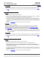
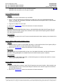
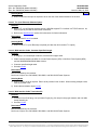
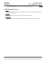
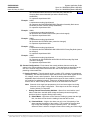
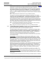
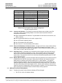
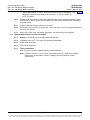
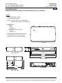
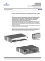
The later version cabinet has been modified to allow the LMS1000 Display Interface circuit card to be plugged
into the 10th LMS1000 I/O circuit card mounting slot. To determine exactly which kit is compatible with your
19" cabinet, look at the LMS1000 I/O circuit card backplane connectors. If all backplane connectors are
uniform, you have the earlier version cabinet and must use kit P/N 524354 (586505000 List 61). If the 10th I/O
backplane connector is longer then the others, you have a later version cabinet that uses Kit P/N 524353
(586505000 List 60). See the following illustration.
Requires the right-most I/O circuit card mounting slot.
Requires LMS1000 firmware 5.0.0 or later.
Requires use of the LMS1000 OEM2 Port. CANNOT be used if List 84 ordered.
Not for use in 23" cabinets.
Not for use in Spec. Nos. 582140000, 582140001, and 582126100 Power Systems.
Page 18 of 69
This document is property of Emerson Network Power, Energy Systems, North America, Inc. and contains confidential and proprietary information owned by Emerson Network Power, Energy
Systems, North America, Inc. Any copying, use, or disclosure of it without the written permission of Emerson Network Power, Energy Systems, North America, Inc. is strictly prohibited.
System Application Guide
Spec. No. 586505000 (Model LMS1000)
Spec. No. 586505500 (Model LMS1000)
SAG586505000
SAG586505500
Issue AU, May 10, 2010
Home
Determines earlier version vs. later version 19" cabinet.
Front Door
Opened in
Illustration
Earlier Version Cabinet: I/O slot #10 is the same as the other I/O slots.
USE KIT P/N 524354 (586505000 List 61)
Later Version Cabinet: I/O Slot #10 has a larger (30 pos.) connector.
USE KIT P/N 524353 (586505000 List 60)
Ordering Notes
1) Order one (1) List 60 to provide a front panel display and keypad in a later version 586505000 19"
cabinets. This option is factory installed if ordered with the system. This option is also field installable.
List 61: LMS1000 Display Option (for use in earlier version 586505000 19" cabinets)
Features
♦
Provides a front panel display and keypad.
♦
Allows local access to the system without a terminal.
♦
You can view plant voltage and load current, view active alarms, perform channel scans, view the Events
Log and Alarm Log, view channel statistics, and view battery discharge history.
Restrictions
There are two kits offered for the 19" cabinet. One kit is used with the earlier version cabinet, the other for the
later version cabinet.
586505000 List 1 cabinets manufactured on or before 3/21/03, use kit P/N 524354 (586505000 List 61).
586505000 List 1 cabinets manufactured after 3/21/03, use kit P/N 524353 (586505000 List 60).
The later version cabinet has been modified to allow the LMS1000 Display Interface circuit card to be plugged
into the 10th LMS1000 I/O circuit card mounting slot. To determine exactly which kit is compatible with your
19" cabinet, look at the LMS1000 I/O circuit card backplane connectors. If all backplane connectors are
uniform, you have the earlier version cabinet and must use kit P/N 524354 (586505000 List 61). If the 10th I/O
backplane connector is longer then the others, you have a later version cabinet that uses Kit P/N 524353
(586505000 List 60). See the above illustration.
Requires LMS1000 firmware 5.0.0 or later.
Requires use of the LMS1000 OEM2 Port. CANNOT be used if List 84 ordered.
Not for use in 23" cabinets.
Not for use in Spec. Nos. 582140000, 582140001, and 582126100 Power Systems.
Page 19 of 69
This document is property of Emerson Network Power, Energy Systems, North America, Inc. and contains confidential and proprietary information owned by Emerson Network Power, Energy
Systems, North America, Inc. Any copying, use, or disclosure of it without the written permission of Emerson Network Power, Energy Systems, North America, Inc. is strictly prohibited.
System Application Guide
Spec. No. 586505000 (Model LMS1000)
Spec. No. 586505500 (Model LMS1000)
SAG586505000
SAG586505500
Issue AU, May 10, 2010
Home
Ordering Notes
1) Order one (1) List 61 to provide a front panel display and keypad in an earlier version 586505000 19"
cabinets. This option is field installable.
List 62: LMS1000 Display Option (for use in 586505000/586505500 23" cabinets)
Features
♦
Provides a front panel display and keypad.
♦
Allows local access to the system without a terminal.
♦
You can view plant voltage and load current, view active alarms, perform channel scans, view the Events
Log and Alarm Log, view channel statistics, and view battery discharge history.
Restrictions
Requires the right-most I/O circuit card mounting slot
(see List 63 for a kit that DOES NOT require the right-most I/O slot).
Requires LMS1000 firmware 5.0.0 or later.
Requires use of the LMS1000 OEM2 Port. CANNOT be used if List 84 ordered.
Not for use in 19" cabinets.
Not for use in Spec. Nos. 582140000, 582140001, and 582126100 Power Systems.
Ordering Notes
1) Order one (1) List 62 to provide a front panel display and keypad in a 23" cabinet. This option is factory
installed if ordered with the system. This option is also field installable.
586505000 List 62 provides a new 23" off-white front panel.
586505500 List 62 provides a new 23" gray front panel.
List 63: LMS1000 Display Option (for use in 586505000/586505500 23" cabinets)
Features
♦
Provides a front panel display and keypad.
♦
Allows local access to the system without a terminal.
♦
You can view plant voltage and load current, view active alarms, perform channel scans, view the Events
Log and Alarm Log, view channel statistics, and view battery discharge history.
♦
Similar to List 61 that DOES NOT require the use of the 10th I/O slot.
Restrictions
Requires LMS1000 firmware 5.0.0 or later.
Requires use of the LMS1000 OEM2 Port. CANNOT be used if List 84 ordered.
Not for use in 19" cabinets.
Not for use in Spec. Nos. 582140000, 582140001, and 582126100 Power Systems.
Ordering Notes
1) Order one (1) List 63 to provide a front panel display and keypad in a 23" cabinet. This option is factory
installed if ordered with the system. This option is also field installable.
Page 20 of 69
This document is property of Emerson Network Power, Energy Systems, North America, Inc. and contains confidential and proprietary information owned by Emerson Network Power, Energy
Systems, North America, Inc. Any copying, use, or disclosure of it without the written permission of Emerson Network Power, Energy Systems, North America, Inc. is strictly prohibited.
System Application Guide
Spec. No. 586505000 (Model LMS1000)
Spec. No. 586505500 (Model LMS1000)
SAG586505000
SAG586505500
Issue AU, May 10, 2010
586505000 List 63 provides a new 23" off-white front panel.
586505500 List 63 provides a new 23" gray front panel.
Home
List 70: Modem Circuit Card
Features
♦
Provides for remote communications up to 56K BPS.
♦
An RJ-11 jack (for telephone line connection) is provided on the rear of the 586505000/586505500
cabinet. In a Spec. No. 582140000, 582140001, and 582126100 Power System; the RJ-11 jack located
on the circuit card is used.
♦
Plugs onto the Main CPU circuit card.
♦
Refer to the "Specifications" section of this document for further information.
Restrictions
For use in a 586505000/586505500 Main Cabinet or 582140000/582140001/582126100 Primary Bay only.
Required for remote terminal or pager alarm notification via the System Alarm Reporting and/or Individual
User Alarm Reporting mechanisms.
Ordering Notes
1) Order a List 70 modem circuit card if remote communications and/or alarm reporting over a telephone line
is required.
List 78: LMS Dual MCA Interface Software Option
Features
♦
Allows the MCA in a Spec. No. 582140000, 582140001, or 582126100 NETSURE Power System (NPS) to
interface with the MCA in a Vortex Power System (VPS) via the LMS.
♦
Refer to the "Specifications" section of this document for further information.
Restrictions
Can only be used in the integrated LMS of a Spec. Nos. 582140000, 582140001, and 582126100 systems.
Operation of Energy Management is disabled when the Dual MCA Interface option is installed.
Ordering Notes
1) Order List 78 if a 582140000, 582140001, or 582126100 system is to interface with an MCA in a Vortex
Power System (VPS) via the LMS.
List 79: Gateway Port Software Option
Features
♦
Allows the LMS1000 to emulate a “dumb” RS-232 asynchronous terminal interface. When installed, user
input through either a local or remote LMS1000 port is directed to the customer equipment connected to
the LMS1000 Gateway port.
♦
Refer to the "Specifications" section of this document for further information.
Page 21 of 69
This document is property of Emerson Network Power, Energy Systems, North America, Inc. and contains confidential and proprietary information owned by Emerson Network Power, Energy
Systems, North America, Inc. Any copying, use, or disclosure of it without the written permission of Emerson Network Power, Energy Systems, North America, Inc. is strictly prohibited.
System Application Guide
Spec. No. 586505000 (Model LMS1000)
Spec. No. 586505500 (Model LMS1000)
SAG586505000
SAG586505500
Issue AU, May 10, 2010
Home
Restrictions
In the 586505000/586505500 system, the Gateway port is provided via the LMS1000 OEM1 port. CANNOT
be used if List 85, List 86, or List 88 ordered.
In the Spec. Nos. 582140000, 582140001, and 582126100 Power Systems; the Gateway port is provided via
the port located on the front of the LMS1000 CPU circuit card installed in the Primary Bay.
Refer to the "Specifications" section of this document for further restrictions.
Ordering Notes
1) Order List 79 if a Gateway Port is required.
2) If you are connecting the Gateway Port to a DGU, also order null modem cable P/N 545562 (5’) or
545783 (50’). This cable connects between the DGU and the LMS1000.
List 80: Door Access Controller (DAC) Interface
Features
♦
Configure and monitor the Door Access Controller via LMS1000.
♦
Refer to the "Specifications" section of this document for further information.
Restrictions
Interfaces to a Desarrollos Digitales Door Access Controller Model MKC-1 only.
The DAC Port is provided via the OEM3 (VPS/NPS) Port. If used with a VPS/NPS, customer must provide a
"Y" cable to allow both the Door Access Controller and VPS/NPS to be connected to the LMS1000 OEM3
Port.
Recommended to use a Desarrollos Digitales Isolation Board (Model DTP-1-485 / 96-DC24-T, E) between the
DAC and LMS1000.
Not for use in Spec. Nos. 582140000, 582140001, and 582126100 Power Systems.
Ordering Notes
1) Order List 80 as required.
List 82: PCU/Rectifier Sequencing Software Option
Features
♦
Provides PCU/Rectifier Sequential Start.
♦
Refer to the "Specifications" section of this document for further information.
Restrictions
Besides the sequencing software option, LMS1000 requires dedicated binary (VPS/NPS and traditional
rectifiers) and relay (traditional rectifiers only) inputs/outputs to manage the power plant. See the Wiring
section of the Installation Instructions (Section 5879).
The LMS1000 Sequencing feature is not for use in 582140000, 582140001, and 582126100 Power Systems.
Ordering Notes
1) Order List 82 if PCU/Rectifier Sequencing is required.
2) Order a binary circuit card if spare inputs are not available for a Commercial AC Fail/Transfer Detection
input and a Standby On/Proper Operate Detection input. (Binary channel 9011 'All AC Off' may be used
as the Commercial AC Fail/Transfer Detection input in a VPS/NPS Power System).
Page 22 of 69
This document is property of Emerson Network Power, Energy Systems, North America, Inc. and contains confidential and proprietary information owned by Emerson Network Power, Energy
Systems, North America, Inc. Any copying, use, or disclosure of it without the written permission of Emerson Network Power, Energy Systems, North America, Inc. is strictly prohibited.
System Application Guide
Spec. No. 586505000 (Model LMS1000)
Spec. No. 586505500 (Model LMS1000)
SAG586505000
SAG586505500
Issue AU, May 10, 2010
3) Order analog, binary, and relay circuit cards as required when used with 'traditional rectifiers'.
Home
List 83: Energy Management Software Option
Features
♦
Provides PCU/Rectifier Energy Management
♦
Refer to the "Specifications" section of this document for further information.
Restrictions
Besides the energy management software option, LMS1000 requires dedicated analog, binary, and relay
(traditional rectifiers only) inputs/outputs to manage the power plant. See the Wiring section of the Installation
Instructions (Section 5879).
The LMS1000 Energy Management feature is not for use in Spec. Nos. 582140000, 582140001, and
582126100 Power Systems.
Ordering Notes
1) Order List 83 if PCU/Rectifier Energy Management is required.
2) Order analog, binary, and relay circuit cards as required when used with 'traditional rectifiers'.
List 84: External GPS Modem Interface
Features
♦
Provides access to the LMS1000 via an external GPS Modem.
♦
Refer to the "Specifications" section of this document for further information.
Restrictions
Interfaces to an Enfora GPS External Modem only.
External Modem Port is provided via the LMS1000 OEM2 Port. CANNOT be used if List 60, 61, 62, or 63
ordered.
Not for use in Spec. Nos. 582140000, 582140001, and 582126100 Power Systems.
Ordering Notes
1) Order List 84 as required.
List 85: AC Analyzer Interface
Features
♦
LMS1000 reads and records values from the AC Analyzer.
♦
Refer to the "Specifications" section of this document for further information.
Restrictions
Interfaces to a Dossena AC Analyzer Model MV3DL only.
AC Analyzer Port is provided via the LMS1000 OEM1 Port. CANNOT be used if List 79, List 86, or List 88
ordered.
Not for use in Spec. Nos. 582140000, 582140001, and 582126100 Power Systems.
Page 23 of 69
This document is property of Emerson Network Power, Energy Systems, North America, Inc. and contains confidential and proprietary information owned by Emerson Network Power, Energy
Systems, North America, Inc. Any copying, use, or disclosure of it without the written permission of Emerson Network Power, Energy Systems, North America, Inc. is strictly prohibited.
System Application Guide
Spec. No. 586505000 (Model LMS1000)
Spec. No. 586505500 (Model LMS1000)
SAG586505000
SAG586505500
Issue AU, May 10, 2010
Home
Ordering Notes
1) Order List 85 as required.
List 86: TL1/X.25 Software Option
Features
♦
Provides a TL1/X.25 Interface and RS-232 Port with PAD support.
♦
Refer to the "Specifications" section of this document for further information.
Restrictions
TL1/X.25 Port is provided via the LMS1000 OEM1 Port. CANNOT be used if List 79, List 85, List 88, or List
90 ordered.
Not for use in Spec. Nos. 582140000, 582140001, and 582126100 Power Systems.
Ordering Notes
1) Order List 86 if TL1/X.25 is required (see also List 90 for another TL1 option).
List 87: Power Metering Software Option
Features
♦
Refer to the "Specifications" section of this document for further information.
Restrictions
This option must be factory installed, or field installed by Emerson Network Power only. This option can be
field installed remotely via dial-up phone lines if your LMS1000 is equipped with a modem or via Ethernet if
connected to a TCP/IP network.
Ordering Notes
1) Order List 87 if Power Metering is required.
2) Order a List 20 analog circuit card. This analog circuit card provides 4 analog inputs. One will be
connected to system voltage. This leaves three for measuring customer loads. Order one additional
analog circuit card per four additional customer loads to be monitored. Note that there is also an 8-input
analog circuit card (List 22) available which monitors up to eight 50 mv shunts.
3) Also order one (1) in-line fuse kit to protect the analog leads connected to system voltage. Specify List
BE (3/8” ring lug), List BF (5/16” ring lug), or P/N 535135 (1/4” ring lug, 3/8” ring lug, or butt splice).
4) And order a current limit resistor kit for each customer load to be monitored for power consumption.
Specify List BA (3/8” ring lug), List BB (splice), or List BC (ring lug for #10 stud)
List 88: Local Port Redirection to OEM 1 Port Option
Features
♦
Local communications access is provided via the rear OEM 1 port instead of the front panel port.
Restrictions
The local port is redirected to the LMS1000 OEM1 Port. CANNOT be used if List 79, List 85, or List 86
ordered.
Not for use in Spec. Nos. 582140000, 582140001, and 582126100 Power Systems.
Page 24 of 69
This document is property of Emerson Network Power, Energy Systems, North America, Inc. and contains confidential and proprietary information owned by Emerson Network Power, Energy
Systems, North America, Inc. Any copying, use, or disclosure of it without the written permission of Emerson Network Power, Energy Systems, North America, Inc. is strictly prohibited.
System Application Guide
Spec. No. 586505000 (Model LMS1000)
Spec. No. 586505500 (Model LMS1000)
SAG586505000
SAG586505500
Issue AU, May 10, 2010
Home
Ordering Notes
1) Order List 88 if the local port is required to be on the rear of the cabinet instead of on the front.
List 90: TL1 (over Ethernet) Software Option
Features
♦
With the TL1 (over Ethernet) software option, LMS1000 supports TL1 interface in a TCP/IP network. An
Ethernet port is provided for this network connection.
♦
Refer to the "Specifications" section of this document for further information.
Restrictions
CANNOT be used if List 86 is ordered.
Ordering Notes
1) Order List 90 if TL1 (over Ethernet) is required (see also List 86 for another TL1 option).
List 92: MCA Interface Cable, Customer Specified Length
Features
♦
A category 5, four twisted pair conductor, 24 AWG solid copper cable.
♦
Cable connects between the MCA of a Vortex Power System (VPS) or NETSURE Power System (NPS)
and the 586505000/586505500 Main Cabinet.
♦
Customer specified length cable.
♦
See also List 94.
Restrictions
Must be assemble by the customer.
Not for use in Spec. Nos. 582140000, 582140001, and 582126100 Power Systems.
Ordering Notes
1) Order multiple List 92 as required. Each List 92 provides 5 feet of cable. When ordering multiple List 92,
cable is provided uncut.
2) Order cable termination kit per List 93.
List 93: MCA Interface Cable Termination Kit
Features
♦
Consists of one RJ-45 plug, one 9-pin male D-type plug, four snap-in crimp type contacts, and one cable
clamp assembly kit.
♦
See also List 94.
Restrictions
Must be assembled by the customer.
Not for use in Spec. Nos. 582140000, 582140001, and 582126100 Power Systems.
Page 25 of 69
This document is property of Emerson Network Power, Energy Systems, North America, Inc. and contains confidential and proprietary information owned by Emerson Network Power, Energy
Systems, North America, Inc. Any copying, use, or disclosure of it without the written permission of Emerson Network Power, Energy Systems, North America, Inc. is strictly prohibited.
System Application Guide
Spec. No. 586505000 (Model LMS1000)
Spec. No. 586505500 (Model LMS1000)
SAG586505000
SAG586505500
Issue AU, May 10, 2010
Home
Ordering Notes
1) Order one (1) List 93 if cable ordered per List 92.
2) Order cable per List 92.
List 94: MCA Interface Cable, Pre-assembled
Features
♦
Cable connects between the MCA of a Vortex Power System (VPS) or NETSURE Power System (NPS)
and the 586505000/586505500 Main Cabinet.
♦
6' long pre-assembled cable.
♦
See also Lists 92 and 93.
Restrictions
Not for use in Spec. Nos. 582140000, 582140001, and 582126100 Power Systems.
Ordering Notes
1) Order one (1) List 94 (a six-foot cable terminated at one end with an RJ-45 plug, and at the other end with
a 9-pin male D-type plug). Note: Another cable option would be P/N 500819 which is a 1.75' cable
terminated at one end with an RJ-45 plug, and at the other end with a 9-pin male D-type plug.
List BA: Current Limit Resistor Kit
Features
♦
Provides one (1) 49.9 Ohm resistor pigtail assembly with a 3/8" ring Iug.
♦
Used to protect analog inputs as described under List 20 and List 22 description.
♦
Can also be used to protect binary inputs as described under List 30 and 31 description.
Ordering Notes
1) Order as required.
List BB: Current Limit Resistor Kit
Features
♦
Provides one (1) 49.9 Ohm resistor pigtail assembly with a splice connection.
♦
Used to protect analog inputs as described under List 20 and List 22 description.
♦
Can also be used to protect binary inputs as described under List 30 and 31 description.
Ordering Notes
1) Order as required.
List BC: Current Limit Resistor Kit
Features
♦
Provides one (1) 49.9 Ohm resistor pigtail assembly with 5/16" ring lug.
♦
Used to protect analog inputs as described under List 20 and List 22 description.
Page 26 of 69
This document is property of Emerson Network Power, Energy Systems, North America, Inc. and contains confidential and proprietary information owned by Emerson Network Power, Energy
Systems, North America, Inc. Any copying, use, or disclosure of it without the written permission of Emerson Network Power, Energy Systems, North America, Inc. is strictly prohibited.
System Application Guide
Spec. No. 586505000 (Model LMS1000)
Spec. No. 586505500 (Model LMS1000)
♦
SAG586505000
SAG586505500
Issue AU, May 10, 2010
Can also be used to protect binary inputs as described under List 30 and 31 description.
Home
Ordering Notes
1) Order as required.
List BE: In-Line Fuse Kit
Features
♦
Provides one (1) in-line fuse (1A) pigtail assembly with a 3/8" ring lug.
♦
Used to protect analog inputs as described under List 20 and List 23 description.
Ordering Notes
1) Order as required.
List BF: In-Line Fuse Kit
Features
♦
Provides one (1) in-line fuse (1A) pigtail assembly with a 5/16" ring lug.
♦
Used to protect analog inputs as described under the List 20 and List 23 descriptions.
Ordering Notes
1) Order as required.
List ST: Temperature Sensor
Features
♦
Provides one (1) temperature probe to be used with the List 21 temperature input circuit card.
♦
Mounts to a 5/16 or M8 stud.
Restrictions
LMS1000 Temperature Probe Wire Specifications:
•
Preferred wire is P/N 1562077, 18 Ga. solid twisted pair, maximum length is 200 feet.
•
Optional wire is P/N 1562001, 20 Ga. shielded twisted pair (shield grounded at one end), maximum
length is 100 feet.
Ordering Notes
1) Order List ST as required.
List SU: Temperature Sensor
Features
♦
Provides one (1) temperature probe to be used with the List 21 temperature input circuit card.
♦
Mounts to a 1/4 or M6 stud.
Restrictions
LMS1000 Temperature Probe Wire Specifications:
•
Preferred wire is P/N 1562077, 18 Ga. solid twisted pair, maximum length is 200 feet.
Page 27 of 69
This document is property of Emerson Network Power, Energy Systems, North America, Inc. and contains confidential and proprietary information owned by Emerson Network Power, Energy
Systems, North America, Inc. Any copying, use, or disclosure of it without the written permission of Emerson Network Power, Energy Systems, North America, Inc. is strictly prohibited.
System Application Guide
Spec. No. 586505000 (Model LMS1000)
Spec. No. 586505500 (Model LMS1000)
SAG586505000
SAG586505500
Issue AU, May 10, 2010
•
Optional wire is P/N 1562001, 20 Ga. shielded twisted pair (shield grounded at one end),
maximum length is 100 feet.
Home
Ordering Notes
1) Order List SU as required.
Page 28 of 69
This document is property of Emerson Network Power, Energy Systems, North America, Inc. and contains confidential and proprietary information owned by Emerson Network Power, Energy
Systems, North America, Inc. Any copying, use, or disclosure of it without the written permission of Emerson Network Power, Energy Systems, North America, Inc. is strictly prohibited.
System Application Guide
Spec. No. 586505000 (Model LMS1000)
Spec. No. 586505500 (Model LMS1000)
SAG586505000
SAG586505500
Issue AU, May 10, 2010
Home
ACCESSORY DESCRIPTIONS
In-Line Fuse Kit, P/N 535135
Features
♦
Provides one (1) in-line fuse (1A) pigtail assembly with a butt splice on one end and the other end
unterminated (a butt splice, 1/4” ring lug, and 3/8" ring lug are provided loose to be crimped on the
unterminated end as required).
♦
Used to protect analog inputs as described under List 20 and List 23 description.
Ordering Notes
1) Order P/N 535135 as required.
Replacement CPU Memory
Backup Battery
Features
♦
The CPU circuit card employs a 3 volt 170 mAH lithium battery which has a shelf life of ten years. Under
typical discharge conditions (25 degrees C), the battery can power the memory for about 5000 hours.
♦
When the lithium battery reaches approximately 2.5 volts; a local indicator illuminates, the Hardware
Failure contacts on the Main CPU card change state, and the firmware generates a Self Diagnostic Error.
When this happens it means the lithium battery, under typical conditions, will be able to power the
memory for about another ten days.
Restrictions
Emerson Network Power recommends that the memory backup battery be replaced once a year.
Ordering Notes
1) Order Part No. 241163100.
LMS1000 Network Cables
Features
♦
Cables to connect the 586505000/586505500 Main Cabinet, 586505000/586505500 Expansion Cabinets,
and 586505000/586505500 Expansion Assemblies into the LMS1000 Network.
Restrictions
In Spec. Nos. 582140000, 582140001, and 582126100 Power Systems; order cable options per
SAG582140000, or SAG582140001, or SAG582126100.
Ordering Notes
1) Cable options include a standard length cable as specified in a), or a customer specified length of cable
as specified in b). The customer must assemble the cable specified in b).
a) Standard Length Cable:
Part No. 421842700, a 6 foot long cable terminated at both ends with an RJ-45 plug.
Part No. 509900, a 4 foot long cable terminated at both ends with an RJ-45 plug.
b) Cable Only: Part No. 156202100, a category 5, four twisted pair conductor, 24 AWG solid copper
cable. Specify length in 5 feet increments (cable is provided uncut). Also order termination kit
specified in c).
Page 29 of 69
This document is property of Emerson Network Power, Energy Systems, North America, Inc. and contains confidential and proprietary information owned by Emerson Network Power, Energy
Systems, North America, Inc. Any copying, use, or disclosure of it without the written permission of Emerson Network Power, Energy Systems, North America, Inc. is strictly prohibited.
System Application Guide
Spec. No. 586505000 (Model LMS1000)
Spec. No. 586505500 (Model LMS1000)
SAG586505000
SAG586505500
Issue AU, May 10, 2010
c) Cable Termination Kit: Part No. 483589500, consists of two RJ-45 plugs.
Home
130VDC Monitoring Wire Harness
Features
♦
Cable harness to monitor 130VDC inputs via the LMS1000 List 20 Four (4) Input analog card providing a
SELV input of 0-50mVDC.
Restrictions
Requires available input on a List 20 Four (4) Input analog card per measurement.
Ordering Notes
1) Order one (1) P/N 520839 130VDC Monitoring Wire Harness per 130VDC input to be monitored, as
required.
Page 30 of 69
This document is property of Emerson Network Power, Energy Systems, North America, Inc. and contains confidential and proprietary information owned by Emerson Network Power, Energy
Systems, North America, Inc. Any copying, use, or disclosure of it without the written permission of Emerson Network Power, Energy Systems, North America, Inc. is strictly prohibited.
System Application Guide
Spec. No. 586505000 (Model LMS1000)
Spec. No. 586505500 (Model LMS1000)
SAG586505000
SAG586505500
Issue AU, May 10, 2010
Home
SPECIFICATIONS
1. 586505000/586505500 LMS1000 SYSTEM
1.1
Environmental Ratings
1.1.1
Operating Ambient Temperature Range: -40°C to +60°C (-40°F to +140°F).
1.1.2
Storage Temperature Range: -40°C to +85°C (-40°F to +185°F).
1.1.3
Humidity: This system is capable of operating in an ambient relative humidity range of 0% to
95%, noncondensing.
1.1.4
Altitude: The maximum operating ambient temperature should be derated by 10°C at an
elevation of 10,000 feet above sea level. For elevations between 3,000 feet and 10,000 feet,
derate the maximum operating ambient temperature linearly.
1.1.5
Safety Compliance:
(A) This unit is UL Recognized to the requirements of UL 1950, Standard for Information
Technology Equipment, for use in Telephone, Electronic Data Processing or Information
Processing Equipment.
(B) This unit meets the requirements of CSA 22.2, No. 950 and is tested and Certified by UL
("c UR") for use in Telephone, Electronic Data Processing or Information Processing
Equipment.
1.2
Firmware Specifications
Note: If connected to an MCA, the MCA Interface provides additional analog and binary channels.
These channels are dedicated to monitor predetermined MCA parameters.
1.2.1
The unit supports a maximum of one (1) user logged in at a time per method of access (i.e.
local port, modem port, Ethernet port, SNMP port, TL1/X.25 port, TL1 [over Ethernet] port).
(A) The unit supports fixed IP addresses and does not support the DHCP protocol.
(B) The unit supports a single TELNET session.
1.3
1.2.2
Users: 8, maximum.
1.2.3
Analog Channels: 700, maximum, and MCA interface channels.
1.2.4
Binary Channels: 700, maximum, and MCA interface channels.
1.2.5
Function Channels: 64, maximum.
1.2.6
Relay Channels: 100, maximum.
1.2.7
LED Channels: 8, maximum.
1.2.8
Energy Management Channels: 80, maximum.
1.2.9
Groups of Channels: 8, maximum.
1.2.10
Information Pages: 3, maximum.
1.2.11
Status Pages: 16, maximum.
1.2.12
Programmable Commands: 8, maximum.
Node Specifications
1.3.1
Maximum Number of Nodes Supported: 25.
1.3.2
Maximum Length of Node Cabling:
(A) Node-to-Node: 250 Meters.
Page 31 of 69
This document is property of Emerson Network Power, Energy Systems, North America, Inc. and contains confidential and proprietary information owned by Emerson Network Power, Energy
Systems, North America, Inc. Any copying, use, or disclosure of it without the written permission of Emerson Network Power, Energy Systems, North America, Inc. is strictly prohibited.
System Application Guide
Spec. No. 586505000 (Model LMS1000)
Spec. No. 586505500 (Model LMS1000)
SAG586505000
SAG586505500
Issue AU, May 10, 2010
Home
(B) Total Wire Length of All Node-to-Node Segments: 450 Meters (1476 Feet).
This is the maximum length of the entire LMS100 Network, and is calculated by
adding up the length of every network cable used to interconnect the Main Cabinet,
Expansion Cabinets, and Expansion Assemblies. Refer to the Installation Instructions
(Section 5879) for cable assembly instructions.
1.4
Software Features
1.4.1
User Interface: Users can interface with LMS1000 through the local port using a local
terminal, through a modem (if optional modem installed), through the Ethernet port via a
TELNET session, through the Ethernet port using a MIB browser, or through the Ethernet port
over the Internet via a WEB Browser.
The local port default parameters are 8 data bits, 1 stop bit, and no parity. These defaults
cannot be changed. The data rate of the local port is software selectable from 110 to 19200
bits/s. The data rate is factory set to 19200 bits/s.
The modem port default parameters are 8 data bits, 1 stop bit, and no parity. These defaults
cannot be changed. When answering, the data rate of the internal modem switches to match
the incoming call. When reporting, the modem data rate will be set to the speed that is
programmed in the user configuration of the user being called. When the modem performs a
callback, it will call at the speed it answered at.
A user can also interface with LMS1000 via a Telnet session. The LMS1000 presently
supports only one Telnet session at a time. To support a Telnet session or MIB browser
access, the unit’s IP address must be set using the IP command.
1.4.2
Security: When a user logs onto the system, the user is prompted to enter a "User
Password".
User configurations provide a "User Access Level" which can be used to limit the
commands available to a particular user through the local and remote ports.
The SNMP feature does not support multiple access levels.
Added security for Ethernet connections is provided via the user configurable Host
address list.
1.4.3
Unit Identification: Each LMS1000 can be uniquely identified through a programmable unit
name, unit number, system identifier (TL1 option), unit header, and unit pager code.
Each LMS1000 is uniquely identified through a programmable unit TCP/IP address.
1.4.4
Alarm Classes: The alarm class feature allows easier relay and LED programming, and helps
classify and identify alarms in system reports and scans. There are eight alarm classes
(numbered 1 through 8) available. Individual channel alarms (Analog, Binary, etc.) can be
assigned to a particular Alarm Class. This Alarm Class then appears as part of the SCAN,
ALARMS, and LOG reports to help identify the type of alarm. Relay control programs can be
as simple as R0001 = K2, which means relay channel one will energize when there is an
alarm for any channel whose Alarm Class is two.
1.4.5
Introduction to Channels:
(A) Channel Identification (I/O Numbering Scheme): The LMS1000 provides analog and
binary input monitoring points, and extended relay contact output points. In addition, local
front panel programmable LEDs are provided. Each input and output point is directly
associated with a channel. Thus there are LMS1000 analog, binary, relay, and LED
channels. In the LMS100, you can combine two or more analog inputs into one function
channel, and advance software options provide energy management channels. This
adds function channels and energy management channels to the list of channel types in
the LMS1000.
Page 32 of 69
This document is property of Emerson Network Power, Energy Systems, North America, Inc. and contains confidential and proprietary information owned by Emerson Network Power, Energy
Systems, North America, Inc. Any copying, use, or disclosure of it without the written permission of Emerson Network Power, Energy Systems, North America, Inc. is strictly prohibited.
System Application Guide
Spec. No. 586505000 (Model LMS1000)
Spec. No. 586505500 (Model LMS1000)
SAG586505000
SAG586505500
Issue AU, May 10, 2010
Home
In the LMS1000 system; the 586505000/586505500 Main Cabinet or
582140000/582140001/582126100 Primary Bay, the 586505000/586505500
Expansion Cabinets or 582140000/582140001/582126100 Secondary Bays, the
586505000/586505500 Expansion Assemblies, and the MCA Interface are referred to as
nodes. A node is a grouping of I/O's in a common assembly, cabinet, or bay.
LMS1000 channels are identified through a type designation (A = analog, B = binary,
R = relay, L = LED, F = function, and E = energy management), a Node Number (I/O
grouping) prefix, and an input/output number. Remember, a particular channel’s type
designation and input/output number is identical to that of the input or output associated to it.
•
Installed optional LMS1000 I/O circuit cards in the 586505000/586505500 Main Cabinet
or 582140000/582140001/582126100 Primary Bay and each 586505000/586505500
Expansion Cabinet or 582140000/582140001/582126100 Secondary Bay are
automatically detected by LMS1000 firmware. Inputs and outputs are automatically
assigned consecutive numbers (per cabinet or bay) for each type detected, starting with
the circuit card of that type installed in the left most position (as viewed from the front).
Types are A for analog, B for Binary, and R for relay. Temperature inputs are mapped
to analog channels.
The Node Number is a fixed number for the 586505000/586505500 Main Cabinet (Node
00), and includes all I/O's associated to the 586505000/586505500 Main Cabinet. For
the 582140000/582140001/582126100, Node 00 is the grouping of LMS1000 I/O cards
installed in the Primary Bay. Node 00 also includes the LED, Function, and Energy
Management channels. For both 586505000/586505500 and
582140000/582140001/582126100, you assign Node Numbers (21-89) to the groupings
of LMS1000 I/O cards installed in 586505000/586505500 Expansion Cabinets and
582140000/582140001/582126100 Secondary Bays during the Initial Start-Up
procedure.
•
Input numbers for the LMS1000 MCA Interface are pre-assigned (The LMS1000 MCA
Interface provides additional analog channels and binary channels. These channels are
dedicated to the LMS1000 MCA Interface, and are automatically mapped to monitor
predetermined MCA parameters.). The Node Number for the LMS1000 MCA Interface
is 90 for all Vortex or NETSURE Power Systems except the Spec. Nos. listed next. The
Node Number for the LMS1000 MCA Interface to Spec. Nos. 582140000, 582140001,
and 582126100 NETSURE Power Systems is 99.
•
Input numbers for the LMS1000 Interface to Spec. Nos. 582140000, 582140001, and
582126100 NETSURE Power System Bays are pre-assigned (The LMS1000 Bay
Interface provides additional analog channels and binary channels. These channels are
dedicated to the LMS1000 Bay Interface, and are automatically mapped to monitor
predetermined parameters.). The Node Number for each Bay is 1 through 20, starting
with the Primary Bay.
•
The LMS1000 also provides self diagnostic alarms on binary channels B0081 through
B0099.
Example: A0001,
A represents an analog input/channel
00 represents the 586505000/586505500 Main Cabinet Node or
582140000/582140001/582126100 Primary Bay LMS1000 I/O Grouping Node
(cannot be changed)
01 represents input/channel #01
Example: A3001,
A represents an analog input/channel
30 represents the 586505000/586505500 Expansion Cabinet Node or
Page 33 of 69
This document is property of Emerson Network Power, Energy Systems, North America, Inc. and contains confidential and proprietary information owned by Emerson Network Power, Energy
Systems, North America, Inc. Any copying, use, or disclosure of it without the written permission of Emerson Network Power, Energy Systems, North America, Inc. is strictly prohibited.
System Application Guide
Spec. No. 586505000 (Model LMS1000)
Spec. No. 586505500 (Model LMS1000)
SAG586505000
SAG586505500
Issue AU, May 10, 2010
582140000/582140001/582126100 Secondary Bay LMS1000 I/O
Grouping Node set as Node #30 (set when network initially
established)
01 represents input/channel #01
Home
Example: A4001,
A represents an analog input/channel
40 represents the 586505000/586505500 Expansion Assembly Node set as
Node #40 (set when network initially established)
01 represents input/channel #01
Example: A9001,
A represents an analog input/channel
90 represents the VPS/NPS MCA Node (cannot be changed)
01 represents input/channel #01
Example: A9901,
A represents an analog input/channel
99 represents the NPS MCA Node (cannot be changed)
01 represents input/channel #01
Example: A0101,
A represents an analog input/channel
01 represents the 582140000/582140001/582126100 Primary Bay Node (cannot
be changed)
01 represents input/channel #01
Example: A0201,
A represents an analog input/channel
02 represents an 582140000/582140001/582126100 Secondary Bay Node
(cannot be changed)
01 represents input/channel #01
(B) Channel Configurations: Each channel has certain attributes that are used by the
system in the various software features it provides. These attributes are presented to the
user in the channel configurations which allow the user to enter specific information
pertaining to these attributes.
(1) Analog Channels: These channels monitor a variety of DC voltages or temperatures.
Additionally, with external interfaces, these channels can monitor other signals such as
AC voltages, current, and oil pressure. Each of the analog channels has four
adjustable alarm limits that can be programmed to report an alarm condition, or record
this condition for statistical purposes. Alarms can be distinguished as low or high
alarms, and an "Alarm Polarity" attribute can be set to further define the alarm.
Note: Channels of the eight input temperature circuit card are assigned as Analog
Channels in the system configuration. These inputs can be set to display in
Celsius (default) or Fahrenheit.
•
Analog Channel Alarm Polarity Attribute: Allows for a more intuitive use of
Alarm Limits when used with plant voltage and battery shunts that typically
provide a bipolar or negative analog input reading.
a) Default Mode: High alarm occurs when the reading is greater than the high
limit; low alarm occurs when the reading is less than the low limit.
b) Polarized Mode: A high or low alarm can only occur if the polarity of the
alarm matches the polarity of the reading. This is useful for detecting both
high charge and discharge currents on a battery shunt. For example,
assume a shunt is wired for a negative float current reading, and it has a high
Page 34 of 69
This document is property of Emerson Network Power, Energy Systems, North America, Inc. and contains confidential and proprietary information owned by Emerson Network Power, Energy
Systems, North America, Inc. Any copying, use, or disclosure of it without the written permission of Emerson Network Power, Energy Systems, North America, Inc. is strictly prohibited.
System Application Guide
Spec. No. 586505000 (Model LMS1000)
Spec. No. 586505500 (Model LMS1000)
SAG586505000
SAG586505500
Issue AU, May 10, 2010
Home
alarm limit of –6.0 amps to detect a high float current. It can then
also have a high limit of +100.0 amps to detect a high discharge
current. So, in this example there are two high alarms, with opposite polarity.
c) Negative Mode: In the negative mode, the alarm processing is reversed
from the default behavior. In other words, a high alarm occurs when the
reading is less than the high limit, and a low alarm occurs when the reading
is the greater than low limit. This is intended for inputs when the reading is
always negative, such as plant voltage, making it possible to have
conventional alarm limits. For example, –56.0V can be a high limit (given a
float voltage of –54.0V).
(2) Binary Channels: Typical binary inputs include alarm and status indications, and any
input with an on and off state. Each of the binary channels can be programmed to
report an alarm condition, or record this condition for statistical purposes.
(3) Energy Management Channels: See description of Energy Management channels
under "Software Options" found later in this document.
(4) Function Channels: Two or more constants, analog channels, and/or function
channels can be programmed into a single function channel. Examples are using the
data from various analog channels to obtain load sums and averages, or multiplying
two channels together to obtain a power value. Each of the function channels has four
adjustable alarm limits that can be programmed to report an alarm condition, or record
this condition for statistical purposes.
(5) LED Channels: Eight programmable status LED indicators are provided on the front
of the Main CPU card. These LEDs can be programmed to illuminate red, green, or
amber (via the LED channels) at specific events or occurrences.
(6) Relay Channels: Each relay channel can be programmed to activate or deactivate
the associated relay at a specific event or occurrence, or to be associated to an energy
management channel when the energy management and/or sequencing option is
ordered.
Note: Relay channels are not required when the energy management and/or
sequencing option is used to control VPS/NPS PCUs.
1.4.6
Groups: The group feature permits organizing analog, binary, function, LED, relay, and
energy management channels together under one common name as a group. Each group is
programmed with a unique name, and may contain any or all channels. This feature enables
the user to extract information concerning the group, such as alarm reports and statistics, by
using the group name or number instead of each individual channel name.
1.4.7
Alarm Reporting: The system can be programmed to activate an alarm when the monitored
activity connected to any input (or the value of a mathematical expression between various
inputs) increases or decreases past a predetermined level, or when any relay or status LED
indicator associated with the system energizes or illuminates. When an alarm condition occurs
on an input (analog, binary, or function channel), the system can be programmed to notify the
user through local visual indicators, extended alarm relay contacts, remote terminal, pager,
Email, and/or TL1 network (when TL1 option is ordered). Remote terminal, pager, Email,
and/or TL1 network (when TL1 option is ordered) notification of an alarm condition is also
available if an alarm condition occurs on an output (relay or LED channel). All system alarms
are reported via the SNMP interface.
There are two types of alarm reporting mechanisms available for remote terminal, pager, or
Email notification; SYSTEM ALARM REPORTING and INDIVIDUAL USER ALARM
REPORTING. System Alarm Reporting has priority over Individual User Alarm Reporting. The
system has an automatic log-off feature. This feature will automatically log off a user who is
communicating remotely with the system via modem, if the system needs to issue an alarm
Page 35 of 69
This document is property of Emerson Network Power, Energy Systems, North America, Inc. and contains confidential and proprietary information owned by Emerson Network Power, Energy
Systems, North America, Inc. Any copying, use, or disclosure of it without the written permission of Emerson Network Power, Energy Systems, North America, Inc. is strictly prohibited.
System Application Guide
Spec. No. 586505000 (Model LMS1000)
Spec. No. 586505500 (Model LMS1000)
SAG586505000
SAG586505500
Issue AU, May 10, 2010
report to that or another remote terminal via the modem.
Home
In addition to System Alarm Reporting and Individual User Alarm Reporting, TL1 Report
Messages are issued via the LMS1000 TL1 port when the TL1 software option is installed.
The automatic log-off feature mentioned above is automatically disabled for the TL1 port. See
the description of the TL1 software option.
See also the description of the SNMP software feature for its alarm reporting mechanisms.
1.4.8
System Alarm Reporting: This method is designed to satisfy the requirements of
maintenance personnel. In this method, the system as a whole is programmed to report alarm
conditions to a specific user (or a sequence of users if the primary user cannot be reached) if
an alarm occurs on any channel programmed for System Alarm Reporting. When an alarm
condition occurs on a channel configured for System Alarm Reporting, the system attempts
alarm notification by either dialing the first user in the predetermined calling sequence or by
Emailing the first user. If this user is reached, the alarm report is given in the mode (pager,
modem, or Email) configured for the specified user. System Alarm Reporting is considered
successful when:
a) the system connects with a modem or an Email notification is sent to a valid Email
address,
or
b) the user issues an ACKnowledgement after receiving the alarm notification.
One of the above options is selected during initial system programming. If alarm reporting is
not successful, the system continues, calling or Emailing the next specified user. If each user
is called or Emailed and an alarm report is not successfully issued, the system waits the
specified retry time interval and then repeats the process.
1.4.9
Individual User Alarm Reports: This method provides each user with the capability of
receiving four different reports, with the first three listed pertaining only to channels that the
user has selected. These reports can be delivered by the system to the user through a pager
(via modem), remote terminal (via modem), or Email (via Ethernet). These reports are:
(A) Occurred Alarm Reports: a report of any new alarms that have occurred on the user’s
channels.
(B) Retired Alarm Reports: a report of any alarms that have cleared on the user’s channels.
(C) Persistent Alarm Reports: a periodic report of any alarms that still exist on the user’s
channels.
(D) Daily Report: The user specifies a standard system command or one of the
programmable commands which is issued as this report. The daily report is given at a
specific time each day.
1.4.10
Alarm Cut-Off (ACO): The alarm cut-off feature enables silencing an external alarm by deenergizing the system alarm relay connected to it. All relays configured for alarm cut-off are
de-energized by issuing a command. Another command can be issued to cancel alarm cut-off.
This feature operates by masking (preventing) existing analog and binary alarm conditions
from affecting a relay's control program. These alarms are considered cancelled and no longer
figure into the evaluation of the relay's control program. Any cancelled alarm that clears and
then turns in again DOES have the ability to affect a relay's operation.
A relay channel attribute termed the "Cycle Frequency" is designed for use with external alarm
circuitry that has its own alarm cut-off. More specifically, this is for applications where an
external ACO has silenced an audible alarm but it is desired to have it turn in again after a
preset amount of time. The cycle frequency allows energized system relays to temporarily turn
off for 15 seconds, thus providing another "open to close" transition to turn in the audible alarm
again.
Page 36 of 69
This document is property of Emerson Network Power, Energy Systems, North America, Inc. and contains confidential and proprietary information owned by Emerson Network Power, Energy
Systems, North America, Inc. Any copying, use, or disclosure of it without the written permission of Emerson Network Power, Energy Systems, North America, Inc. is strictly prohibited.
System Application Guide
Spec. No. 586505000 (Model LMS1000)
Spec. No. 586505500 (Model LMS1000)
SAG586505000
SAG586505500
Issue AU, May 10, 2010
Home
1.4.11
Information Pages: Three user programmable information pages (or screens) can
be entered in the system. These information pages can be viewed by any user.
These pages can serve as a note pad or location of instructions for users.
1.4.12
Status Pages: Sixteen user programmable status pages (or screens) can be formatted in the
system. These pages permit the displaying of scan information derived from separate
channels on a single page format. SCAN information includes the present value and alarm
status of a channel, plus other pertinent information.
1.4.13
Programmable Commands: Eight user programmable commands can be entered in the
system. A programmable command combines up to eight standard commands into a single
command which then can be executed by typing the name given to the programmable
command.
1.4.14
Mail: Users have the ability to send mail (messages) to other users, or to themselves.
1.4.15
Alarm Log: The system stores a listing of the 500 latest alarms that have occurred.
1.4.16
Event Log: The system stores a listing of the 500 latest events that have occurred.
1.4.17
Analog Channel Maximum Load Percentages (Rate Report): This feature determines how
plant (battery and rectifier) capacities and other sizing limits (fuses, circuit breakers, and wire
sizes) are faring under actual load conditions. This feature allows the customer to easily
determine the maximum load percentage (that has occurred) versus an analog channel alarm
limit. This feature divides the maximum peak value of an analog input and the highest hourly
average into a designated alarm limit and presents the results as percentages. These
percentages inform the customer how close a channel's peak and high hourly average values
are in relation to its alarm limit(s).
1.4.18
Battery Discharge Timer: The LMS1000 can record Battery Discharge History. A Binary,
LED, or Relay channel must be identified to monitor the "On Battery" condition. Analog or
Function channels must be identified to monitor the Plant Voltage and Plant Load. The Battery
Discharge Timer feature displays the last 50 recorded discharges in a tabular format. The
information displayed includes the duration of the battery discharge, the time and date at which
the discharge began, the lowest recorded plant voltage during the discharge, and the average
plant load.
1.4.19
Battery Thermal Runaway: In a VPS/NPS, the LMS1000 is capable of overriding system
output voltage (controlled by the MCA) to avoid thermal runaway.
1.4.20
MCA Interface: The MCA Interface allows an LMS1000 User to communicate with the MCA
located in a Vortex Power System (VPS) or a NETSURE Power System (NPS). This allows a
User to monitor, adjust, and control the VPS/NPS via LMS1000. This interface also enables
LMS1000 to control the PCUs in the Power System via the features available in LMS1000.
One simple cable connection between the LMS1000 and the MCA completes the
interconnections required in a VPS/NPS Power System (except Spec. Nos. 582140000,
582140001, and 582126100). The LMS1000 is factory integrated in a Spec. No. 582140000,
582140001, and 582126100 NETSURE Power System and requires no customer
interconnection.
The same tasks accomplished via the MCA local interface pad can be done via the LMS1000.
This includes alarm monitoring, system voltage/current monitoring, adjustment of system/alarm
circuits, setting system configuration, and setting system calibration. In addition, the LMS1000
automatically maps dedicated analog and binary channels to the Power System. This enables
existing LMS1000 features (e.g. alarm log, alarm reporting, analog statistics) to be easily used
with the Power System. Also, LMS1000 maintains a history of MCA/Power System
configuration and events.
The MCA Interface requires an RS-485 circuit card to be installed on the MCA in the Power
System (except Spec. Nos. 582140000, 582140001, and 582126100). Spec. Nos.
Page 37 of 69
This document is property of Emerson Network Power, Energy Systems, North America, Inc. and contains confidential and proprietary information owned by Emerson Network Power, Energy
Systems, North America, Inc. Any copying, use, or disclosure of it without the written permission of Emerson Network Power, Energy Systems, North America, Inc. is strictly prohibited.
System Application Guide
Spec. No. 586505000 (Model LMS1000)
Spec. No. 586505500 (Model LMS1000)
SAG586505000
SAG586505500
Issue AU, May 10, 2010
582140000, 582140001, and 582126100 MCA Interface is factory integrated and
does not require additional hardware.
Home
Note: The MCA interface in a Spec. No. 582140000, 582140001, or 582126100 Power
system only supports one (1) MCA "CAN Input/Output" circuit card per bay.
Each task supported by the MCA Interface is listed below (for VPS and NPS Power
Systems other than Spec. Nos. 582140000, 582140001, and 582126100).
Available to all LMS1000 Users via the ALARMS NETSURE Commands
•
View Active VPS/NPS System Alarms
•
View Active VPS/NPS Subsystem Alarms
•
View Active VPS/NPS MCA Alarms
•
View Active VPS/NPS Shunt Alarms
•
View Active VPS/NPS LVD Alarms
Available to all LMS1000 Users via the SCAN NETSURE Commands
•
View VPS/NPS System Status and Alarms…
System Output Voltage
Total System Output Current
Individual System Output Currents (individual shunts)
Temperature Probe Values and Alarm Status
System Alarms (includes PCU and Temperature Probe alarms)
•
View VPS/NPS Subsystem Status and Alarms (if installed)…
Subsystem Output Voltage
Total Subsystem Output Current
Individual Subsystem Output Currents (individual shunts)
Subsystem Alarms
•
View VPS/NPS PCU Status…
Total PCU Current
Individual PCU Currents
•
View VPS/NPS Battery Status and Alarms (if battery Shunt PODs installed)…
Total Battery Current
Individual Battery Currents
Battery Alarms
•
View VPS/NPS MCA Alarms
•
View VPS/NPS LVD Alarms
Available to LMS1000 Users with Access to Level 2
Commands via the PRCONFIG NETSURE Commands
•
View VPS/NPS Settings…
System Float Voltage
System Test/Equalize Voltage
System High Voltage Alarm #1
System High Voltage Alarm #2
System Battery On Discharge Alarm
System 50% Battery On Discharge Alarm
System High Voltage Shutdown
System Overcurrent Alarm
System Current Limit
System Output Voltage Calibration Reading
Page 38 of 69
This document is property of Emerson Network Power, Energy Systems, North America, Inc. and contains confidential and proprietary information owned by Emerson Network Power, Energy
Systems, North America, Inc. Any copying, use, or disclosure of it without the written permission of Emerson Network Power, Energy Systems, North America, Inc. is strictly prohibited.
System Application Guide
Spec. No. 586505000 (Model LMS1000)
Spec. No. 586505500 (Model LMS1000)
SAG586505000
SAG586505500
Issue AU, May 10, 2010
NAG Minutes (Audible Alarm Cutoff Reset Time Period)
Battery Charge Temperature Compensation Module's Calibration Voltage
Subsystem High Voltage Alarm (if installed)
Subsystem Low Voltage Alarm (if installed)
Subsystem Output Voltage Calibration Reading (if installed)
Subsystem Overcurrent Alarm (if installed)
Battery Overcurrent Alarm
Auto Equalize Multiplier
Digital Temperature Compensation Slope
Digital Temperature Compensation Maximum Voltage
Digital Temperature Compensation Minimum Voltage
Battery Current Limit
Relay Test Time
Test/Equalize Timeout
Low Voltage Disconnect "Disconnect" (for each installed LVD)
Low Voltage Disconnect "Reconnect" (for all installed LVDs)
Temperature Probes Alarms
•
Home
View VPS/NPS Equipment Inventory...
PCUs
System Shunts
Subsystem Shunts
Battery Shunts
LVDs
Temperature Probes
Vacant PCU Mounting Positions
Maximum System Current Capacity
System Operating Mode (Float or Equalize [forced, manual, timed, auto])
Temperature Compensation Mode (None, Analog, Digital [Highest, Averaged, Probe #1])
MCA Customer Text Message (custom name), Spec. No., Serial No., Software Version
Each PCU Customer Text Message (custom name), Spec. No., Serial No.,
Output Voltage Rating, Current Rating
Available to Indicated LMS1000 Users via the SET NETSURE Commands
LMS1000 Users with Access to Level 4 Commands
•
Set VPS/NPS NAG Minutes (Audible Alarm Cutoff Reset Time Period)
LMS1000 Users with Access to Level 5 Commands
•
Set VPS/NPS System High Voltage Alarm #1 Setting
•
Set VPS/NPS System High Voltage Alarm #2 Setting
•
Set VPS/NPS System Battery On Discharge Alarm Setting
•
Set VPS/NPS System 50% Battery On Discharge Alarm (Voltage is Very Low Alarm)
Setting
•
Set VPS/NPS System Overcurrent Alarm Setting
•
Set VPS/NPS Subsystem High Voltage Alarm Setting (if installed)
•
Set VPS/NPS Subsystem Low Voltage Alarm Setting (if installed)
•
Set VPS/NPS Subsystem Overcurrent Alarm Setting (if installed)
•
Set VPS/NPS Relay Test Time
•
Set VPS/NPS Temperature Probe Alarms
•
Set VPS/NPS Auto Equalize Multiplier
Page 39 of 69
This document is property of Emerson Network Power, Energy Systems, North America, Inc. and contains confidential and proprietary information owned by Emerson Network Power, Energy
Systems, North America, Inc. Any copying, use, or disclosure of it without the written permission of Emerson Network Power, Energy Systems, North America, Inc. is strictly prohibited.
System Application Guide
Spec. No. 586505000 (Model LMS1000)
Spec. No. 586505500 (Model LMS1000)
SAG586505000
SAG586505500
Issue AU, May 10, 2010
LMS1000 Users with Access to Level 6 Commands
Home
•
Set VPS/NPS MCA Remote Access Password
•
Set VPS/NPS System Operating Mode (Float or Test/Equalize)
•
Set VPS/NPS System Output Voltage Calibration Reading
•
Set VPS/NPS Subsystem Output Voltage Calibration Reading (if installed)
•
Reset VPS/NPS System Output Voltage Calibration Reading to Factory Default
•
Reset VPS/NPS Subsystem Output Voltage Calibration Reading to Factory Default (if
installed))
•
Set VPS/NPS Analog Battery Charge Temperature Compensation Module's Calibration
Voltage
•
Set VPS/NPS Number of 25A, 50A, 100A, and 200A PCU Mounting Positions Available in
the System (also custom PCU sizes can be set)
•
Reset VPS/NPS Inventory to Reflect Current System Configuration
•
Set VPS/NPS System Float Voltage Setting
•
Set VPS/NPS System Test/Equalize Voltage Setting
•
Set VPS/NPS System High Voltage Shutdown Setting
•
Set VPS/NPS System Current Limit Setting
•
Set VPS/NPS Low Voltage Disconnect "Disconnect" Settings for all Installed LVDs
•
Set VPS/NPS Low Voltage Disconnect "Reconnect" Setting
•
Manually Reconnect a Specified LVD.
•
Set VPS/NPS PCU Fan Speed (fast, slow)
•
Set VPS/NPS PCU Load Share Alarm (on, off)
•
Set VPS/NPS PCU State (on, off)
•
Set VPS/NPS Digital Battery Charge Temperature Compensation Source (Highest,
Averaged, Probe #1)
•
Set VPS/NPS Battery Overcurrent Alarm Setting
•
Set VPS/NPS Digital Battery Charge Temperature Compensation (Slope, Min. Voltage,
Max. Voltage)
•
Set VPS/NPS Battery Current Limit
•
Set VPS/NPS Test/Eq Timeout
•
Set VPS/NPS Individual PCU Custom Text Messages
•
Set VPS/NPS Custom Text Message for MCA
•
Set VPS/NPS Interface (on, off)
Available to LMS1000 Users with Access to Level 6 Commands via the
DOWNLOAD NETSURE , DOWNLOAD TFTP NETSURE , UPLOAD NETSURE ,
and UPLOAD TFTP NETSURE Commands, respectively
•
Download the Configuration of the VPS/NPS to an ASCII File
•
Upload a Previously Downloaded Configuration to the VPS/NPS
Each task supported by the MCA Interface is listed below for NPS Power Systems Spec.
Nos. 582140000, 582140001, and 582126100.
Available to LMS1000 Users with Access to Level 2
Commands via the PRCONFIG NPS Commands
•
View NPS System Float Voltage Setting
Page 40 of 69
This document is property of Emerson Network Power, Energy Systems, North America, Inc. and contains confidential and proprietary information owned by Emerson Network Power, Energy
Systems, North America, Inc. Any copying, use, or disclosure of it without the written permission of Emerson Network Power, Energy Systems, North America, Inc. is strictly prohibited.
System Application Guide
Spec. No. 586505000 (Model LMS1000)
Spec. No. 586505500 (Model LMS1000)
SAG586505000
SAG586505500
Issue AU, May 10, 2010
•
View NPS System Test/Equalize Voltage Setting
•
View NPS System High Voltage Shutdown Setting
•
View NPS System Current Limit Setting
•
View NPS System High Voltage Alarm #1 Setting
•
View NPS System High Voltage Alarm #2 Setting
•
View NPS System Battery On Discharge Alarm Setting
•
View NPS System Voltage is Very Low Alarm Setting
•
View NPS System Total Load Current Alarm Setting
•
View NPS System Group A Load Current Alarm Setting
•
View NPS System Group B Load Current Alarm Setting
•
View NPS System High Temperature Alarm #1 Setting
•
View NPS System High Temperature Alarm #2 Setting
•
View NPS System Low Temperature Alarm #1 Setting
•
View NPS System Low Temperature Alarm #2 Setting
•
View NPS NAG Minutes (Audible Alarm Cutoff Reset Time Period) Setting
•
View NPS Manual Test/Equalize Time Setting
•
View NPS Relay Test Time Setting
•
View NPS Auto Equalize Time Multiplier Setting
•
View NPS Temperature Compensation Slope Setting
•
View NPS Temperature Compensation Maximum Voltage Setting
•
View NPS Temperature Compensation Minimum Voltage Setting
•
View NPS Inventory
Home
Available to Indicated LMS1000 Users via the SET NPS Commands
LMS1000 Users with Access to Level 4 Commands
•
Set NPS NAG Minutes (Audible Alarm Cutoff Reset Time Period)
LMS1000 Users with Access to Level 5 Commands
•
Set NPS System Battery On Discharge Alarm Setting
•
Set NPS System Voltage is Very Low Alarm Setting
•
Set NPS System High Voltage Alarm #1 Setting
•
Set NPS System High Voltage Alarm #2 Setting
•
Set NPS System Total Load Current Alarm Setting
•
Set NPS System Group A Load Current Alarm Setting
•
Set NPS System Group B Load Current Alarm Setting
•
Set NPS Relay Test Time Setting
•
Set NPS System High Temperature Alarm #1 Setting
•
Set NPS System High Temperature Alarm #2 Setting
•
Set NPS System Low Temperature Alarm #1 Setting
•
Set NPS System Low Temperature Alarm #2 Setting
•
Set NPS System Power Share Capacity Setting
Page 41 of 69
This document is property of Emerson Network Power, Energy Systems, North America, Inc. and contains confidential and proprietary information owned by Emerson Network Power, Energy
Systems, North America, Inc. Any copying, use, or disclosure of it without the written permission of Emerson Network Power, Energy Systems, North America, Inc. is strictly prohibited.
System Application Guide
Spec. No. 586505000 (Model LMS1000)
Spec. No. 586505500 (Model LMS1000)
SAG586505000
SAG586505500
Issue AU, May 10, 2010
LMS1000 Users with Access to Level 6 Commands
•
Set NPS System Operating Mode (Float or Test/Equalize)
•
Turn any Installed NPS PCU On or Off (TR Feature)
•
Set NPS MCA Remote Access Password
•
Set Custom Text Messages for NPS Elements
•
Set NPS System Float Voltage Setting
•
Set NPS System Test/Equalize Voltage Setting
•
Set NPS System High Voltage Shutdown Setting
•
Set NPS System Current Limit Setting
•
Perform a Relay Test
•
Set NPS Manual Test/Equalize Time Setting
•
Set NPS Auto Equalize Time Multiplier Setting
•
Set NPS Temperature Readings to Celsius
•
Set NPS Temperature Readings to Fahrenheit
•
Set NPS Temperature Compensation Slope Setting
•
Set NPS Temperature Compensation Maximum Voltage Setting
•
Set NPS Temperature Compensation Minimum Voltage Setting
•
Reset NPS Inventory to Reflect Current System Configuration
•
Set the following parameters for NPS MCA CAN I/O circuit cards
•
Designate Analog Input as "Auxiliary" or "Distribution"
•
Set the Scale Factor for Analog Input and Output
•
Designate the Alarm State for Binary Inputs
•
Set Custom Text Messages (Names)
•
Enable or disable NPS System Alternate Current Limit operation
•
Set NPS System Alternate Current Limit Capacity setting
•
Set NPS System Sequencing Delay setting
Home
Available to LMS1000 Users with Access to Level 6 Commands via the
DOWNLOAD NPS, DOWNLOAD TFTP NPS, UPLOAD NPS,
and UPLOAD TFTP NPS Commands, respectively
1.4.21
•
Download the Configuration of the NPS to an ASCII File
•
Upload a Previously Downloaded Configuration to the NPS
IP Parameters
(A) The system "IP" address can be set.
(B) The "Gateway Address" can be set and listed.
(C) The "Netmask Address" can be set and listed.
1.5
Standard Software Features
1.5.1
WEB Interface Software Feature
•
Allows you to access the LMS1000 over the Internet via a WEB Browser.
•
Read access only for security.
•
Displays LMS1000 status in a simple three-pane WEB Interface.
Page 42 of 69
This document is property of Emerson Network Power, Energy Systems, North America, Inc. and contains confidential and proprietary information owned by Emerson Network Power, Energy
Systems, North America, Inc. Any copying, use, or disclosure of it without the written permission of Emerson Network Power, Energy Systems, North America, Inc. is strictly prohibited.
System Application Guide
Spec. No. 586505000 (Model LMS1000)
Spec. No. 586505500 (Model LMS1000)
SAG586505000
SAG586505500
Issue AU, May 10, 2010
•
Top pane for LMS1000 identification, alarm notification, and display of system
voltage and system current that updates approximately every 15 seconds.
•
Left pane for navigation.
•
Right pane for display of status information, which includes display of…
Home
Alarms and Logs
Alarm Status (equivalent of the LMS1000 ALARMS command)
Alarm Log (equivalent of the LMS1000 LOG command)
Event Log (equivalent of the LMS1000 EVENTS command)
Equipment
Hardware (equivalent of the LMS1000 BOARDS command)
•
You can configure your own LMS1000 WEB Pages to display. The following User defined
LMS1000 features can be displayed in the WEB Browser…
LMS1000 Status Pages
LMS1000 Channel Groups
LMS1000 User Channels
•
1.5.2
Requires Netscape Navigator (v4.0 or later) or Microsoft Internet Explorer (v4.0 or later).
SNMP Software Feature: LMS1000 supports SNMP (Simple Network Management Protocol)
interface in a TCP/IP network. Communications to and from LMS1000 is accomplished via a
MIB (Management Information Base) browser. An Ethernet port is provided for this network
connection.
(A) SNMP Alarm Reporting via the Ethernet Port: All system alarms are reported via the
SNMP interface. Alarms sent via SNMP traps can be configured for three different types.
These are …
(1) TRAPS OCCURRED, selects reporting of new system alarms that have occurred.
(2) TRAPS RETIRED, selects reporting of system alarms that have cleared.
(3) TRAPS PERSISTENT, selects periodic reporting of system alarms that still exist. The
Persistent Alarm Period specifies how frequently the system will attempt a Persistent
Alarm Report.
(B) SNMP Parameters:
(1) The "Get" community string can be set and listed.
(2) The "Set" community string can be set and listed.
(3) "Trap Addresses" can be added, deleted, and listed. SNMP V1 or V2 traps can be
received. The SNMP version of the traps sent are selected through software (V1 or
V2).
(4) "Host Addresses" can be added, deleted, and listed.
(5) "Trap Addresses" can be enabled and disabled.
1.6
Available Software Options
1.6.1
Gateway Port Software Option (if installed): The Gateway Software Option allows the
LMS1000 to emulate a “dumb” RS-232 asynchronous terminal interface. When installed, user
input through either a local or remote LMS1000 port is directed to the customer equipment
connected to the LMS1000 Gateway port.
Page 43 of 69
This document is property of Emerson Network Power, Energy Systems, North America, Inc. and contains confidential and proprietary information owned by Emerson Network Power, Energy
Systems, North America, Inc. Any copying, use, or disclosure of it without the written permission of Emerson Network Power, Energy Systems, North America, Inc. is strictly prohibited.
System Application Guide
Spec. No. 586505000 (Model LMS1000)
Spec. No. 586505500 (Model LMS1000)
SAG586505000
SAG586505500
Issue AU, May 10, 2010
Home
Restrictions
•
Only one LMS1000 Gateway port supported.
Only one Gateway port User at a time supported.
•
Gateway Port: In the 586505000/586505500 system, the Gateway port is provided via the
LMS1000 OEM1 port. In the 582140000/582140001/582126100 system, the Gateway port
is provided via the port located on the front of the LMS1000 CPU circuit card installed in
the Primary Bay.
•
Session Abort Control: A Gateway session must be manually terminated using the
special Gateway session termination escape sequence. The LMS1000 will not detect an
abort of the Gateway session by the device connected to the Gateway port, nor is it
capable of terminating the session with the device connected to the Gateway port when the
LMS1000 session is aborted abruptly.
•
Loss of Carrier: The LMS1000 will automatically terminate Gateway access established
via modem dial up or TELNET in the event of carrier loss.
•
User Timeout: The Gateway Port is automatically deactivated and the User is returned to
the LMS1000 command prompt if the LMS1000 User Timeout Period is exceeded.
•
Alarm Reporting: When using a dial-up session to communicate with the Gateway port,
dial-out alarm notification via LMS1000 is delayed until the Gateway session is terminated
and control is returned to the LMS1000.
•
With the exception of session inactivity monitoring, any related communications protocol
control (i.e., character echoing) will be performed by the device connected to the Gateway
port.
•
Third party software utilized to communicate with Gateway connected device will need to
first logon to the LMS1000 and enter the CONNECT command.
The LMS1000 does not support any third party proprietary communications protocol
required to communicate with customer equipment connected to the Gateway port.
1.6.2
Power Metering Software Option (if installed): This option allows accurate metering of
power consumed by equipment connected to your power plant. This feature monitors power
consumption of up to sixty-four (64) separate pieces of equipment connected to the power
plant. Power consumption data is generated and stored for any function channel properly
configured for power monitoring. Entering the command POWER generates and displays the
power consumption report. This report may also be generated in a "comma separated value"
format which can easily be imported into a spreadsheet for record keeping or presentation
purposes. The user is responsible for translating power consumption data into dollars billed.
To use this feature, an analog channel must monitor system voltage and other analog channels
must monitor load current for each equipment to be monitored for power consumption. A
function channel must be configured for each equipment to be monitored for power
consumption by entering the phrase "KW" for the "Unit Text", and entering the appropriate
program line to multiply the value of the analog channel monitoring system voltage with the
value of the analog channel monitoring load current, then divide this product by 1000 [i.e.
F01=(A0001*A0002)/1000]. Instead of dividing by 1000, you could multiply by 0.001 [i.e.
F01=A0001*A0002*0.001]
To get a report, enter the command POWER. Any time the POWER command is entered,
LMS1000 generates a power consumption report for the function channels and displays the
resulting information. For the "comma separated value" format, enter the command POWER
CSV. The POWER command is available to a user programmed for access to level 1
commands.
Page 44 of 69
This document is property of Emerson Network Power, Energy Systems, North America, Inc. and contains confidential and proprietary information owned by Emerson Network Power, Energy
Systems, North America, Inc. Any copying, use, or disclosure of it without the written permission of Emerson Network Power, Energy Systems, North America, Inc. is strictly prohibited.
System Application Guide
Spec. No. 586505000 (Model LMS1000)
Spec. No. 586505500 (Model LMS1000)
SAG586505000
SAG586505500
Issue AU, May 10, 2010
To clear the Power Metering data, enter the command CLR POWER. The CLR
POWER command is available to a user programmed for access to level 4
commands.
1.6.3
Home
Energy Management Software Option (if installed): The optional energy management
programming permits an installation to only operate rectifiers/PCUs as needed to maintain the
load and keep batteries in a fully charged condition. As load increases, the energy
management feature will turn on additional rectifiers/PCUs as needed in 15 second intervals
when load requirements exceed a user selectable percent (90-99%) of the total capacity of the
operating rectifiers/PCUs to maintain the load. LMS1000 will also turn off rectifiers/PCUs as
necessary in 15 minute intervals if the load decreases below a separate user selectable
percent of the total capacity of the would be operating rectifiers/PCUs. Rectifiers/PCUs which
are always operating to maintain any load requirements are cycled through the group of
rectifiers/PCUs controlled by this feature to provide uniform operating times for each
rectifier/PCU. This rotation occurs from 1-365 days (at midnight), as selected by the user. The
base rectifier/PCU is rotated decrementally through the group. As an example, first
rectifier/PCU 5 was on at all times, at the programmed time interval rectifier/PCU 4 is on at all
times, and at the next occurrence of the programmed time interval rectifier/PCU 3 will be on at
all times. If energy management is used, all rectifiers/PCUs in the system should be
controlled.
Energy Management Channels: A maximum of 80 energy management channels can be
programmed, thus LMS1000 can support any combination of up to 80 energy managed
rectifiers and PCUs. An energy management channel combines two input channels with a
single output channel (rectifier only) per rectifier/PCU to accomplish the task of controlling the
rectifiers/PCUs for energy management and sequential start purposes.
Note: The number of rectifiers that can be controlled is limited to 32 due to the availability of
32 relay channels dedicated for energy management/sequential start. PCUs do not
require hard wired relay channels for energy management, hence 80 PCUs may be
controlled. Any combination of rectifiers and PCUs may be controlled, up to 80 total, as
long as rectifiers don't exceed 32.
Note: Operation of Energy Management is disabled when the Dual MCA Interface option is
installed.
1.6.4
Sequential Start Software Option (if installed): LMS1000 can support up to 80 sequential
start controlled rectifiers/PCUs (see note above). There are two types of optional sequencing
available with the sequential start option: commercial AC sequencing and standby
sequencing. Commercial AC sequencing permits sequential starting of rectifiers/PCUs
assigned to energy management channels when commercial AC input fails and subsequently
is restored. When AC power is lost and then resumes, the AC sequencing option turns off all
controlled rectifiers/PCUs, and then starts the rectifiers/PCUs sequentially at 15 second
intervals until all controlled rectifiers/PCUs are operating. This prevents commercial AC power
surges which could cause an overload condition possible when several rectifiers/PCUs are
started simultaneously. The standby sequencing option prevents similar surges when
rectifiers/PCUs are powered from a backup AC source, such as an engine-alternator, after a
failure occurs in the commercial AC source. These surges could stall or overload the standby
equipment. LMS1000 senses when the commercial AC input fails and immediately turns off all
controlled rectifiers/PCUs. It waits a programmed time interval and, when it senses that the
standby equipment is operating properly, then sequences the rectifiers/PCUs on at 15 second
intervals until all controlled rectifiers/PCUs are operating. When AC input power resumes,
commercial AC sequencing as described above occurs. Once all controlled rectifiers/PCUs
are restarted, energy management (if supplied) will resume. Rectifier/PCU sequencing has
priority over energy management. Both types of sequencing use binary input changes to
initiate the sequencer.
The sequencer can also be configured with a Sequencer Failsafe Timer feature. This feature
Page 45 of 69
This document is property of Emerson Network Power, Energy Systems, North America, Inc. and contains confidential and proprietary information owned by Emerson Network Power, Energy
Systems, North America, Inc. Any copying, use, or disclosure of it without the written permission of Emerson Network Power, Energy Systems, North America, Inc. is strictly prohibited.
System Application Guide
Spec. No. 586505000 (Model LMS1000)
Spec. No. 586505500 (Model LMS1000)
SAG586505000
SAG586505500
Issue AU, May 10, 2010
Home
aborts sequencer operation when an external monitoring device controlling sequencer
operation fails. The timer starts when LMS1000 detects an AC failure. If the timer
expires before a signal is received, indicating that the commercial AC is restored or load was
transferred to the standby power source, the following occur: The sequencer is disabled, an
entry is made in the event log, the sequencer variables are reset, and all rectifiers/PCUs are
turned on. If a signal is received before the timer expires, the timer is deactivated and reset.
When the sequencer is disabled, the Set Sequence command must be re-issued to re-activate
the sequencer.
Note: Setting the Sequencer Failsafe Timer to zero (0) disables this feature.
The sequencer can also be configured with an AC Restoration Qualification Timer feature.
This feature is only available when the INPUT TYPE attribute of the sequencer is configured as
a FAIL type, and not as a TRANSFER type. This feature allows the sequencer to turn all
rectifiers/PCUs off and start the sequence re-start operation at a specific time interval from
when commercial AC is restored. The timer starts when a signal is received indicating that the
commercial AC is restored. The standby sequencer (if configured) operates normally until the
timer expires. When the timer expires, all rectifiers/PCUs are turned off and the AC sequencer
starts. If AC fails before the timer expires, the timer is deactivated.
Note: The AC Restoration Qualification Timer feature should be set to a few seconds less
than the actual amount of time required for a proper transfer.
Note: Setting the AC Restoration Qualification Timer to zero (0) disables this feature.
1.6.5
TL1/X.25 Software Option (if installed): LMS1000 can operate as a Network Element (NE)
in a Network Maintenance and Administration (NMA) system. An NMA is an Operations
System (OS) developed by Bell Communications Research (Bellcore).
This software option provides support to the specific TL1 commands and messages listed in
the Commands Chapter of the User Instructions (Section 5847). This option also provides an
asynchronous RS-232 port connection. The port is designed to provide an interface to a
network device which converts the asynchronous output to X.25 packets. The packets can
then be sent out across the network to an operations center or user console.
The terms Access Identifier, LMS1000 Access Identifier, and LMS1000 Sub-Access Identifier
are described as follows.
Access Identifier: In a Network Maintenance and Administration (NMA) system, a unique
access identifier (AID) is used to identify each entity contained within the system. LMS1000
must be configured to allow a single access identifier to be used to access and report on an
NMA system entity which may consist of a multiple of sub-entities, each monitored by a variety
of LMS1000 channels. This is accomplished by configuring LMS1000 access identifiers and
LMS1000 sub-access identifiers as described next. A list of suggested access identifiers and
sub-access identifiers appears in TA-NWT-001360, Table 4-1.
LMS1000 can be set to use an "AID delimiter". When enabled, the LMS1000 access identifier
field and the LMS1000 sub-access identifier field in all responses to TL1 commands and
reports containing a TL1 access identifier field is separated by a hyphen. The use of an "AID
delimiter" (a hyphen) can be enabled or disabled, as described in "Setting the TL1/X.25 Port
Parameters" of the System Configuration Chapter in the Installation Instructions (Section
5879).
LMS1000 Access Identifier: Thirty-two (32) LMS1000 access identifiers are available. The
LMS1000 access identifier is used to uniquely identify a system entity (such as a power plant).
LMS1000 Sub-Access Identifier: The LMS1000 sub-access identifiers are used to uniquely
identify each sub-entity of an entity (such as each rectifier, each battery string, etc. contained in
a power plant).
The association between all LMS1000 channels monitoring an individual rectifier, an individual
Page 46 of 69
This document is property of Emerson Network Power, Energy Systems, North America, Inc. and contains confidential and proprietary information owned by Emerson Network Power, Energy
Systems, North America, Inc. Any copying, use, or disclosure of it without the written permission of Emerson Network Power, Energy Systems, North America, Inc. is strictly prohibited.
System Application Guide
Spec. No. 586505000 (Model LMS1000)
Spec. No. 586505500 (Model LMS1000)
SAG586505000
SAG586505500
Issue AU, May 10, 2010
battery string, etc. is made by configuring each channel monitoring this individual subentity with a unique sub-access identifier name. This is done when the individual
LMS1000 channels are configured.
Home
Thus all LMS1000 channels monitoring rectifier one may be configured with the sub-access
identifier name RECT1. All LMS1000 channels monitoring rectifier two may be configured with
sub-access identifier RECT2. All LMS1000 channels monitoring battery string one may be
configured with the sub-access identifier BATSTR1. All LMS1000 channels monitoring battery
string two may be configured with sub-access identifier name BATSTR2. Etc.
Now, to associate the sub-entities (each rectifier, each battery string, etc.) to the entity (the
power plant), you configure the access identifier to include all LMS1000 channels monitoring
this entity and any sub-entity contained within. This is done through the use of the LMS1000
command SET AID.
TL1 Report Messages: When used in a TL1 network, each user is provided with the
capability of receiving TL1 report messages pertaining only to channels that the user has
selected. These messages are delivered by the LMS1000 to the user via the TL1 port. These
messages are:
(A) Report Alarm Messages: A Report Alarm message is issued when a user channel
configured with the notification code attribute "CR", "MJ", or "MN" alarms or retires.
(B) Report Event Messages: A Report Event message is issued when a user channel
configured with the notification code attribute "NA" alarms or retires.
(C) Report Condition Messages: A Report Condition message is a periodic report on all
alarms for user channels configured with the notification code "CR", "MJ", "MN", or "NA"
that have not cleared since the last report was issued. If the report condition interval is set
to a value of zero, this type of report message is disabled.
1.6.6
TL1 (over Ethernet) Software Option (if installed): Same as TL1/X.25 Software Option (see
Paragraph 1.5.5) except TL1 support is provided via the LMS1000 Ethernet port.
1.6.7
LMS Dual MCA Interface Software Option (if installed): This option allows a Spec. No.
582140000, 582140001, and 582126100 NETSURE Power System (NPS) to be integrated with
an existing Vortex Power System.
Requires LMS Firmware version 9.0.1.2 or later.
The option allows system control and monitoring functions to be performed through a single
controller. System related data parameters from the Vortex system are passed to the NPS
controller (MCA). System settings are controlled by the NPS MCA and can be changed either
directly at its front panel interface or indirectly with the LMS’s ‘SET NPS’ commands.
Status of the Vortex Power System parameters are still accessible using the Vortex System
front panel display or associated LMS commands. Changes in settings not associated to
system control can be modified through the LMS’s ‘SET VORTEX’ commands. VPS parameter
readings and status are assigned to LMS nodes ninety and ninety-one. Refer to Accessing a
Vortex Power System in the OPERATION Chapter of the LMS User’s Manual (Section 5847)
for a list of the specific parameter channel assignments.
System settings can be changed using one of two methods.
•
The front panel interface of the NPS main bay. The LMS detects that the setting has been
changed on the NPS’s front panel and also changes the associated setting of the VPS.
•
The LMS’s command line interface using the ‘Set NPS’ commands. The LMS requests the
NPS to change the setting and upon verification the associated VPS setting is updated.
The following VPS readings and statuses are communicated to the NPS controller via the
LMS-NPS LISP communications link.
Page 47 of 69
This document is property of Emerson Network Power, Energy Systems, North America, Inc. and contains confidential and proprietary information owned by Emerson Network Power, Energy
Systems, North America, Inc. Any copying, use, or disclosure of it without the written permission of Emerson Network Power, Energy Systems, North America, Inc. is strictly prohibited.
System Application Guide
Spec. No. 586505000 (Model LMS1000)
Spec. No. 586505500 (Model LMS1000)
SAG586505000
SAG586505500
Issue AU, May 10, 2010
1.7
Home
•
The VPS ‘Total PCU Current’ reading (LMS function channel sixty-four program
line must be ‘F64 = A9005’). The value is summed into NPS Total PCU Current
parameter reading (associated LMS channel A9902).
•
The VPS ‘Total System Current’ reading (LMS function channel sixty-three program line
must be ‘F63 = A9002’). The value is summed into NPS Total Load Current parameter
reading (associated LMS channel A9903).
•
The number of failed VPS PCUs. The NPS uses this to determine the System PCU Major
and System PCU Minor alarms.
•
The VPS ‘Fuse Alarm’ status (LMS LED channel seven program line must be ‘L7 =
B9010’). The status must be configured in the NPS controller function definition to create
an alarm indication.
•
The VPS ‘AC Fail Alarm’ status (LMS LED channel eight program line must be ‘L8 =
B9011’). The status must be configured in the NPS controller function definition to create
an alarm indication.
•
The VPS ‘System Major’ and ‘System Minor’ (the associated LMS channels (B9015 and
B9016) must have the ‘Alarm Class’ parameter configured for LMS Alarm Class ‘MAJOR
and MINOR’ respectively).
Specialty Interfaces
1.7.1
Door Access Controller (DAC) Interface: Provides interface to a Door Access Controller via
the LMS1000 OEM3 Port.
•
The DAC can be configured and monitored via LMS1000.
•
Provides dual control of the door latch (LMS1000 and DAC Keypad). Keypad access can
be enabled and disabled via LMS1000.
•
Provides LMS1000 Binary Channels to monitor DAC Communications, Strike Failure,
Forced Entry, Invalid DAC PIN List, and a Door Open Alarm.
•
Provides LMS1000 Event Log entries for each valid and invalid Key Codes entered.
•
Key codes can be SET, DELETED, LISTED. DAC access via key codes can be enabled
and disabled.
•
Status of door and electric strike can be viewed.
•
An LMS1000 Relay will be used to allow remote control of the Door Latch in the event the
DAC fails. The LMS1000 Relay will be controlled via two user configurable LMS1000
commands to open the door and lock the door.
1.7.2
External GPS Modem Interface: Provides interface to an external modem via the LMS1000
OEM2 Port.
1.7.3
AC Analyzer Interface: Provides interface to an AC Analyzer via the LMS1000 OEM1 Port.
•
Provides LMS1000 Analog Channels to display the various parameters monitored by the
AC Analyzer. Provides an LMS1000 Binary Channel to monitor the communications path
to the AC Analyzer.
2. 586505000/586505500 LMS1000 MAIN CABINET
2.1
Input Ratings
2.1.1
Input Voltage Range: 20 - 60 Volts DC.
2.1.2
Maximum Input Current: 0.7 Amperes.
Page 48 of 69
This document is property of Emerson Network Power, Energy Systems, North America, Inc. and contains confidential and proprietary information owned by Emerson Network Power, Energy
Systems, North America, Inc. Any copying, use, or disclosure of it without the written permission of Emerson Network Power, Energy Systems, North America, Inc. is strictly prohibited.
System Application Guide
Spec. No. 586505000 (Model LMS1000)
Spec. No. 586505500 (Model LMS1000)
2.2
2.3
2.4
SAG586505000
SAG586505500
Issue AU, May 10, 2010
Home
Mounting
2.2.1
586505000 List 1: Furnished reversible mounting angles permit mounting in a 19" or 23" wide
relay rack with 1" or 1-3/4" multiple drilling. 586505000 and 586505500 List 2: Furnished
mounting angles permit mounting in a 23" wide relay rack with 1" or 1-3/4" multiple drilling.
2.2.2
Mounting angles may be re-positioned for flush front mounting, 5-inch front projection
mounting, or 6-inch front projection mounting.
I/O Circuit Card Mounting Positions
2.3.1
Provides for mounting of any combination of I/O (analog, binary, relay, and temperature) circuit
cards. CARDS MUST BE LOADED LEFT TO RIGHT (AS VIEWED FROM THE FRONT OF
THE CABINET). DO NOT SKIP SLOTS.
2.3.2
Contains ten (10) I/O circuit card mounting slots.
CPU Circuit Card, Part No. 545476 (used in 586505000/586505500) and 545558 (used in
582140000, 582140001, and 582126100)
2.4.1
General: The CPU circuit card contains the system's firmware, a power supply circuit,
communications circuits, and programmable local LED indicators. This circuit card can be
equipped with a piggy-back modem circuit card.
2.4.2
Processor: MC 68EN302 - 20MHz.
2.4.3
SRAM - Data: 2M bytes.
2.4.4
Flash - System: 1M bytes.
2.4.5
Flash - Application: 3M bytes.
2.4.6
Real-Time Clock: The time base for the operating system comes from a real time clock. This
integrated circuit is totally self-contained and does not require any calibration. Accuracy=10
PPM (27 seconds per month) or better at nominal temperature.
2.4.7
Low Lithium Battery Detection Circuit: Illuminates a local LED indicator for low lithium
battery indication.
2.4.8
Communications:
Note: The following ports may be different when the LMS1000 is used in a Spec. No.
582140000, 582140001, or 582126100 Power System. Refer to the 582140000,
582140001, or 582126100 system documentation.
(A) Local Port (RS-232): A front panel 9-pin female D-type jack is provided. This jack is
configured as a DCE (Data Communication Equipment). Refer to Table 1 for pin
assignments.
Note: When List 88 is ordered, the port on the front of the 586505000/586505500 cabinet
is inactive, and the local port is redirected to OEM1 located on the rear of the
cabinet. The configuration of the OEM1 port in this application is as shown in Table
2.
(B) Modem Port: An internal 56K bps modem circuit card can be installed onto the CPU
circuit card. The modem circuit card connects to an RJ-11 phone jack located on the rear
of the system cabinet for customer phone line connection.
(C) Ethernet Port: A rear panel RJ-45 10BaseT jack is provided. This jack has a standard
Ethernet pin configuration scheme, twisted pair.
(D) OEM1 Port (RS-232): A 9-pin female D-type jack is provided on the rear panel of the
586505000/586505500 cabinet. This jack is configured as a DTE (Data Terminal
Equipment). Refer to Table 2 for pin assignments. The port's function is determined by
the LMS1000 Software Options or LMS1000 Specialty Interface Options installed.
Page 49 of 69
This document is property of Emerson Network Power, Energy Systems, North America, Inc. and contains confidential and proprietary information owned by Emerson Network Power, Energy
Systems, North America, Inc. Any copying, use, or disclosure of it without the written permission of Emerson Network Power, Energy Systems, North America, Inc. is strictly prohibited.
System Application Guide
Spec. No. 586505000 (Model LMS1000)
Spec. No. 586505500 (Model LMS1000)
SAG586505000
SAG586505500
Issue AU, May 10, 2010
Home
(E) OEM2 Port (RS-232/RS-422): A 9-pin female D-type jack is provided on the rear
of the 586505000/586505500 cabinet. This jack is configured as a DTE (Data
Terminal Equipment). This port is software selectable to provide either an RS-232 or an
RS-422 connection. Refer to Tables 3 and 4 for pin assignments. The port's function is
determined by the LMS1000 Software Options or LMS1000 Specialty Interface Options
installed.
(F) OEM3 VPS/NPS Port (RS-485): A 9-pin female D-type jack is provided on the rear of the
586505000/586505500 cabinet. This jack is used to connect LMS1000 to an MCA located
in a Vortex Power System (VPS) or NETSURE power System (NPS). The port's function is
also determined by the LMS1000 Software Options or LMS1000 Specialty Interface
Options installed. Refer to Table 5 for pin assignments.
(G) LMS1000 Network Ports: Four RJ-45 jacks are provided for interconnecting Expansion
Cabinets and Expansion Assemblies into the LMS1000 network. Refer also to Paragraph
1.3 "Node Specifications".
Port Pin Number
Application
Input/Output
1
2
Transmitted Data (TxD)
Output from System
3
Received Data (RxD)
Input to System
4
Data Set Ready (/DSR)
Output from System
5
Signal Ground (Gnd)
6
Data Terminal Ready (/DTR)
Input to System
7
Clear to Send (/CTS)
Input to System
8
Request to Send (/RTS)
Output from System
9
Note: When List 88 is ordered, the port on the front of the cabinet is
inactive, and the local port is redirected to OEM1 located on the
rear of the cabinet. The configuration of the OEM1 port in this
application is as shown in Table 2. List 88 cannot be used in
conjunction with List 85 (AC Analyzer Interface) or List 86
(TL1/X.25).
Table 1
Front Panel Local Port (9-Pin Female D-Type Jack) Pin Assignments
RS-232 Configured as DCE
Page 50 of 69
This document is property of Emerson Network Power, Energy Systems, North America, Inc. and contains confidential and proprietary information owned by Emerson Network Power, Energy
Systems, North America, Inc. Any copying, use, or disclosure of it without the written permission of Emerson Network Power, Energy Systems, North America, Inc. is strictly prohibited.
System Application Guide
Spec. No. 586505000 (Model LMS1000)
Spec. No. 586505500 (Model LMS1000)
SAG586505000
SAG586505500
Issue AU, May 10, 2010
Home
Port Pin Number
Application
Input/Output
1
2
3
4
5
6
7
8
9
Received Data (RxD)
Transmitted Data (TxD)
Data Terminal Ready (/DTR)
Signal Ground (Gnd)
Data Set Ready (/DSR)
Request to Send (/RTS)
Clear to Send (/CTS)
-
Input to System
Output from System
Output from System
Input to System
Output from System
Input to System
-
Table 2
OEM1 Port (9-Pin Female D-Type Jack) Pin Assignments
RS-232 Configured as DTE
Port Pin Number
Application
Input/Output
1
2
3
4
5
6
7
8
9
Data Carrier Detect (/DCD)
Received Data (RxD)
Transmitted Data (TxD)
Data Terminal Ready (/DTR)
Signal Ground (Gnd)
Data Set Ready (/DSR)
Request to Send (/RTS)
Clear to Send (/CTS)
-
Input to System
Input to System
Output from System
Output from System
Input to System
Output from System
Input to System
-
Table 3
OEM2 Port (9-Pin Female D-Type Jack) Pin Assignments
Software Selected for RS-232 Connection, Configured as DTE
Port Pin Number
Application
Input/Output
1
2
3
4
5
6
7
8
9
Received Data (RxD-)
Received Data (RxD+)
Transmitted Data (TxD+)
Transmitted Data (TxD-)
Signal Ground (Gnd)
Handshake Out (HSO-)
Handshake Out (HSO+)
Handshake In (HSI+)
Handshake In (HSI-)
Input to System
Input to System
Output from System
Output from System
Output from System
Output from System
Input to System
Input to System
Table 4
OEM2 Port (9-Pin Female D-Type Jack) Pin Assignments
Software Selected for RS-422 Connection, Configured as DTE
Page 51 of 69
This document is property of Emerson Network Power, Energy Systems, North America, Inc. and contains confidential and proprietary information owned by Emerson Network Power, Energy
Systems, North America, Inc. Any copying, use, or disclosure of it without the written permission of Emerson Network Power, Energy Systems, North America, Inc. is strictly prohibited.
System Application Guide
Spec. No. 586505000 (Model LMS1000)
Spec. No. 586505500 (Model LMS1000)
SAG586505000
SAG586505500
Issue AU, May 10, 2010
Home
Port Pin Number
Application
Input/Output
1
2
3
4
5
6
7
8
9
-Transmitted Data (TxD)
Received Data (RxD)
-Signal Ground (Gnd)
-----
-Output from System
Input to System
-------
Table 5
OEM3 Port (9-Pin Female D-Type Jack) Pin Assignments
RS-485 Configured as DCE
2.4.9
Controls and Indicators: The following controls and indicators are provided on the CPU
circuit card. Refer to the Operating Chapter in the User Instructions (Section 5847) for
descriptions and locations.
(A) Eight Programmable LED Indicators: Programmable for illumination event and color (red,
amber, or green)
(B) One Programmable Switch (can be used in program lines)
(C) One CPU Reset Pushbutton Switch
(D) One CPU/Hardware Fail LED Indicator
(E) One Power On / Low Lithium Battery LED Indicator
2.5
2.4.10
External CPU/Hardware Fail Alarm Contacts: A single set of Form-C relay contacts change
state when a hardware failure activates one or more of the hardware fail channels. In the
LMS1000, these channels are B0081 through B0099. These contacts are rated for 0.6A at 125
VAC, 0.5A at 110 VDC, and 2.0A at 30 VDC.
2.4.11
Watchdog Circuit: A watchdog circuit constantly monitors program execution and issues a
system reset if it appears the processor is "lost". If the processor is still not functioning after
the first reset, the circuit automatically shuts down the system by performing a permanent
system reset. This permanent reset can be cleared by momentarily depressing the CPU RST
(reset) pushbutton switch.
2.4.12
Memory Backup Battery: All of the information that is programmed by the customer is stored
in RAM memory on the CPU circuit card. When power is removed, the real time clock and
RAM memory are backed up by a lithium battery and a .1 farad capacitor. The capacitor
actually serves two purposes. First, when the memory and clock are on backup power, the
capacitor supplies the load (for about 20 minutes) before the battery takes over. This reduces
the drain on the battery which helps lengthen its life. Second, when a battery is removed, the
capacitor continues to supply power until the new battery is installed. Thus, the contents of the
clock and memory are preserved while the lithium battery is being replaced.
LMS1000 Front Panel Display Option
2.5.1
Provides a front panel vacuum florescent display (VFD) and keypad.
•
The VFD is a 4-line, 20-character display.
Page 52 of 69
This document is property of Emerson Network Power, Energy Systems, North America, Inc. and contains confidential and proprietary information owned by Emerson Network Power, Energy
Systems, North America, Inc. Any copying, use, or disclosure of it without the written permission of Emerson Network Power, Energy Systems, North America, Inc. is strictly prohibited.
System Application Guide
Spec. No. 586505000 (Model LMS1000)
Spec. No. 586505500 (Model LMS1000)
•
2.6
SAG586505000
SAG586505500
Issue AU, May 10, 2010
The keypad consists of 12 keys; numbers 0 through 9, ENTER, and MENU. The
following numeric keys also function as arrow keys: 2 = UP, 8 = DOWN, 4 =
LEFT, 6 = RIGHT.
Home
2.5.2
Provides read only access to view plant voltage and load current, view active alarms, perform
channel scans, view the Events Log and Alarm Log, view channel statistics, and view battery
discharge history.
2.5.3
Requires LMS1000 firmware version 5.0.0 or later.
2.5.4
List 60 and List 62 require I/O card slot #10. List 61 and List 63 use an interconnect harness in
lieu of the 10th I/O slot.
2.5.5
Not for use in Spec. Nos. 582140000, 582140001, and 582126100 Power Systems.
Optional Modem Circuit Card, Part No. 508951
2.6.1
General: Provides for remote communications at 56K bps.
2.6.2
Compatible with CCITT V.22, Bell 212A, and Bell 103 standards.
2.6.3
DTMF and pulse dialing.
2.6.4
FCC Part 68 Registered.
2.6.5
Theory of Operation
Refer to Figure 1 for a flow diagram depicting modem operation.
Note: Additional features (i.e. error control, data compression, etc.) supported by remote
modem must be deactivated. Refer to operating manual supplied by modem
manufacturer.
Page 53 of 69
This document is property of Emerson Network Power, Energy Systems, North America, Inc. and contains confidential and proprietary information owned by Emerson Network Power, Energy
Systems, North America, Inc. Any copying, use, or disclosure of it without the written permission of Emerson Network Power, Energy Systems, North America, Inc. is strictly prohibited.
System Application Guide
Spec. No. 586505000 (Model LMS1000)
Spec. No. 586505500 (Model LMS1000)
SAG586505000
SAG586505500
Issue AU, May 10, 2010
Home
Report to be Made
Terminate
Call Attempt,
Modem goes
On-Hook,
Report Attempt
Failed
NO
Modem goes Off-Hook
Give Reports
Dial Tone Detected
within 5 Seconds
?
More Reports to
Make
?
YES
NO
Attempt Remote
Modem Logon,
See Remote
Modem Logon
Procedure
(Sheet 3)
Dial Phone Number
Terminate
Call Attempt,
Modem goes
On-Hook,
Report Attempt
Failed
Remote Logon
Successful
?
NO
YES
Answer Tone
Detected within 1
Minute
?
NO
YES
Command
Mode
YES
Terminate
Communication
Session
Attempt to Establish
Communication with
Remote Modem
Terminate
Call Attempt,
Modem goes
On-Hook,
Report Attempt
Failed
NO
Communications
Established
?
YES
Figure 1 (Sheet 1 of 3)
Modem Operation - Modem Calling Procedure
Page 54 of 69
This document is property of Emerson Network Power, Energy Systems, North America, Inc. and contains confidential and proprietary information owned by Emerson Network Power, Energy
Systems, North America, Inc. Any copying, use, or disclosure of it without the written permission of Emerson Network Power, Energy Systems, North America, Inc. is strictly prohibited.
System Application Guide
Spec. No. 586505000 (Model LMS1000)
Spec. No. 586505500 (Model LMS1000)
SAG586505000
SAG586505500
Issue AU, May 10, 2010
Home
Ring Signal Detected
by Modem Card
Programmed
Number of
Rings Detected
?
NO
No Further
Action Taken
YES
Modem goes
Off-Hook
Carrier Detected
within 1 Minute
?
YES
Attempt to Establish
Communication with
Remote Modem
Communications
Established
?
NO
YES
NO
Terminate
Answer Attempt,
Modem goes
On-Hook
Prompt User for
Logon Password
Figure 1 (Sheet 2 of 3)
Modem Operation - Modem Answer Procedure
Page 55 of 69
This document is property of Emerson Network Power, Energy Systems, North America, Inc. and contains confidential and proprietary information owned by Emerson Network Power, Energy
Systems, North America, Inc. Any copying, use, or disclosure of it without the written permission of Emerson Network Power, Energy Systems, North America, Inc. is strictly prohibited.
System Application Guide
Spec. No. 586505000 (Model LMS1000)
Spec. No. 586505500 (Model LMS1000)
SAG586505000
SAG586505500
Issue AU, May 10, 2010
Home
Continued from
Modem Calling Procedure
(Sheet 1)
Output Logon
Prompt "ENTER
PASSWORD"
Carriage Return
Detected within
10 seconds
?
NO
Remote Logon
Unsuccessful
YES
NO
Valid Password
Detected
?
NO
Password Entry
Attempt < 3
?
YES
YES
Remote Modem
Logon Successful
Figure 1 (Sheet 3 of 3)
Modem Operation - Remote Modem Logon Procedure
Page 56 of 69
This document is property of Emerson Network Power, Energy Systems, North America, Inc. and contains confidential and proprietary information owned by Emerson Network Power, Energy
Systems, North America, Inc. Any copying, use, or disclosure of it without the written permission of Emerson Network Power, Energy Systems, North America, Inc. is strictly prohibited.
System Application Guide
Spec. No. 586505000 (Model LMS1000)
Spec. No. 586505500 (Model LMS1000)
SAG586505000
SAG586505500
Issue AU, May 10, 2010
3. 586505000/586505500 LMS1000 EXPANSION CABINET
3.1
3.2
3.3
3.4
Home
Input Ratings
3.1.1
Input Voltage Range: 20 - 60 Volts DC.
3.1.2
Maximum Input Current: 0.7 Amperes.
Mounting
3.2.1
586505000 List 6: Furnished reversible mounting angles permit mounting in a 19" or 23" wide
relay rack with 1" or 1-3/4" multiple drilling. 586505000 and 586505500 List 7: Furnished
mounting angles permit mounting in a 23" wide relay rack with 1" or 1-3/4" multiple drilling.
3.2.2
Mounting angles may be re-positioned for flush front mounting, 5-inch front projection
mounting, or 6-inch front projection mounting.
I/O Circuit Card Mounting Positions
3.3.1
Provides for mounting of any combination of I/O (analog, binary, relay, and temperature) circuit
cards. CARDS MUST BE LOADED LEFT TO RIGHT (AS VIEWED FROM THE FRONT OF
THE CABINET). DO NOT SKIP SLOTS.
3.3.2
Contains ten (10) I/O circuit card mounting slots.
CPU Circuit Card, Part No. 506153 (also used in 582140000, 582140001, and 582126100
Secondary Bays)
3.4.1
General: The CPU circuit card contains the LMS1000 Expansion firmware, a power supply
circuit, and communications circuits.
3.4.2
Processor: TMPN3150 - 10MHz.
3.4.3
SRAM - Data: 32K bytes.
3.4.4
Flash - System: 128K bytes.
3.4.5
LMS1000 Network Ports: Four RJ-45 jacks are provided for interconnecting Expansion
Cabinets and Expansion Assemblies into the LMS1000 network.
3.4.6
Controls and Indicators: The following controls and indicators are provided on the CPU
circuit card. Refer to the Operating Chapter in the User Instructions (Section 5847) for
descriptions and locations.
(A) One Power On LED Indicator
(B) One CPU Fail LED Indicator
(C) One CPU Hardware Reset Pushbutton Switch
4. 586505000/586505500 LMS1000 EXPANSION ASSEMBLY
4.1
4.2
Input Ratings
4.1.1
Input Voltage Range: 20 - 60 Volts DC.
4.1.2
Maximum Input Current: 0.2 Amperes.
Mounting
4.2.1
4.3
Customer mounted. See "Overall Dimensions (Expansion Assembly)" under PHYSICAL SIZE
INFORMATION section for details.
I/O Connector Pinouts
4.3.1
See "Connector Locations (Expansion Assembly)" under PHYSICAL SIZE INFORMATION.
Page 57 of 69
This document is property of Emerson Network Power, Energy Systems, North America, Inc. and contains confidential and proprietary information owned by Emerson Network Power, Energy
Systems, North America, Inc. Any copying, use, or disclosure of it without the written permission of Emerson Network Power, Energy Systems, North America, Inc. is strictly prohibited.
System Application Guide
Spec. No. 586505000 (Model LMS1000)
Spec. No. 586505500 (Model LMS1000)
SAG586505000
SAG586505500
Issue AU, May 10, 2010
4.4
Home
CPU Circuit, P/O Part No. 507606
4.4.1
General: The CPU circuit contains the Expansion Assembly's firmware, a power supply circuit,
and communications circuits.
4.4.2
Processor: TMPN3150 - 10MHz.
4.4.3
SRAM - Data: 32K bytes.
4.4.4
Flash - System: 128K bytes.
4.4.5
Analog Inputs: Provides twenty-four (24) 50mv shunt inputs. ±0.1% from -40°C to +65°C.
Common mode voltage between inputs must not exceed –0.15 to +0.95 volts.
4.4.6
Binary Inputs: Provides eight (8) binary inputs.
(A) Single-ended input connections, return is –BAT.
(B) Input State: An applied voltage of 12 to 60 volts, DC, is defined as the CC (contact
closed) state. An applied voltage of 2.0 volts or less is defined as the CO (contact open)
state. Voltages between 2.0 and 12 volts are undefined.
4.4.7
LMS1000 Network Port: One RJ-45 jack is provided for interconnecting into the LMS1000
network.
5. INPUT/OUTPUT (I/O) CIRCUIT CARDS
5.1
Four (4) Input Analog Circuit Card, Part No. 506336
5.1.1
General: Adds four (4) analog inputs to the system.
5.1.2
Inputs: Monitors 0-50 mv DC (shunts), 0-100 mv DC (shunts), 0-20 ma current loop signals,
and voltages from 0 to 60 volts DC. Each input is jumper selectable for either shunt, current
loop, or voltage. Two sets of terminals provided for each input. One set for connection of 0-60
volts DC. The other set for connection of 50 mv shunts, 100 mv shunts, and 20 ma current
loops.
5.1.3
Channel-to-Channel Isolation: 60 volts, maximum. Inputs are isolated from each other via
an A/D converter block operating from an isolated power supply.
5.1.4
20ma Input: Polarity Sensitive.
5.1.5
Update Frequency: Once every 4 seconds.
5.1.6
Accuracy:
(A) Large Signal Inputs (error in absolute volts)
(1) 5 to 60 VDC @ +25°C: ±0.04V
(2) 5 to 60 VDC @ -40°C to +85°C: ±0.06V
(3) 0 to 5 VDC @ +25°C: ±0.002V
(4) 0 to 5 VDC @ -40°C to +85°C: ±0.006V
(B) Small Signal Inputs (error as % of transducer full scale)
(1) 20 ma current loop transducers @ -40°C to +85°C: ±0.1%
(2) 50 mv and 100 mv shunts @ -40°C to +85°C: ±0.1%
5.2
Eight (8) Input Analog Circuit Card, Part No. 514528
5.2.1
General: Adds eight (8) analog inputs to the system.
Page 58 of 69
This document is property of Emerson Network Power, Energy Systems, North America, Inc. and contains confidential and proprietary information owned by Emerson Network Power, Energy
Systems, North America, Inc. Any copying, use, or disclosure of it without the written permission of Emerson Network Power, Energy Systems, North America, Inc. is strictly prohibited.
System Application Guide
Spec. No. 586505000 (Model LMS1000)
Spec. No. 586505500 (Model LMS1000)
5.2.2
SAG586505000
SAG586505500
Issue AU, May 10, 2010
Inputs: Monitors 0-50 mv DC (shunts).
Home
Common mode voltage between inputs must not exceed –0.15 to +0.95 volts.
5.3
5.4
5.5
5.6
5.7
5.2.3
Channel-to-Channel Isolation: Not Provided. All 8 channels are referenced to the CH-1
return lead (TB1-2)
5.2.4
Update Frequency: Once every 2 seconds.
5.2.5
Accuracy: @ -40°C to +85°C: ±0.1% (error as % of transducer full scale [50mv]).
Twelve (12) Input Analog Circuit Card, Part No. 520838
5.3.1
General: Adds twelve (12) analog inputs to the system.
5.3.2
Inputs: Monitors individual battery cell voltages.
5.3.3
Update Frequency: 10 seconds.
5.3.4
Maximum Cell Voltage: 2.5 volts.
Four (4) Input Binary Circuit Card, Part No. 506332
5.4.1
General: Adds four (4) binary inputs to the system. Double-ended input connections.
5.4.2
Maximum Input Voltage: 60 volts DC.
5.4.3
Channel-to-Channel Isolation: 60 volts, maximum.
5.4.4
Input State: An applied voltage of 12 to 60 volts, DC, is defined as the CC (contact closed)
state. An applied voltage of 2.0 volts or less is defined as the CO (contact open) state.
Voltages between 2.0 and 12 volts are undefined.
5.4.5
Alarm State: Either the CC or CO state may be configured as the alarm state.
Eight (8) Input Binary Circuit Card, Part No. 506334
5.5.1
General: Adds eight (8) binary inputs to the system. Single-ended input connections.
5.5.2
Maximum Input Voltage: 60 volts DC.
5.5.3
Channel-to-Channel Isolation: 60 volts, maximum.
5.5.4
Input State: An applied voltage of 12 to 60 volts, DC, is defined as the CC (contact closed)
state. An applied voltage of 2.0 volts or less is defined as the CO (contact open) state.
Voltages between 2.0 and 12 volts are undefined.
5.5.5
Alarm State: Either the CC or CO state may be configured as the alarm state.
Four (4) Output Form-C Relay Circuit Card, Part No. 506335
5.6.1
General: Adds four (4) Form-C relay output contacts to the system.
5.6.2
Relay Contacts: 4 sets.
5.6.3
Contact Arrangement: Form-C.
5.6.4
Contact Rating: Contacts are rated for 0.6A at 125 VAC, 0.5A at 110 VDC, 2.0A at 30 VDC.
5.6.5
Channel-to-Channel Isolation: 177 volts, maximum.
Eight (8) Input Temperature Circuit Card, Part No. 506333
5.7.1
General: Adds eight (8) temperature inputs to the system.
5.7.2
Accuracy: ±0.5°C, from -10°C to +85°C.
Page 59 of 69
This document is property of Emerson Network Power, Energy Systems, North America, Inc. and contains confidential and proprietary information owned by Emerson Network Power, Energy
Systems, North America, Inc. Any copying, use, or disclosure of it without the written permission of Emerson Network Power, Energy Systems, North America, Inc. is strictly prohibited.
System Application Guide
Spec. No. 586505000 (Model LMS1000)
Spec. No. 586505500 (Model LMS1000)
SAG586505000
SAG586505500
Issue AU, May 10, 2010
Home
PHYSICAL SIZE INFORMATION
Overall Dimensions
(586505000 Main [List 1] and Expansion [List 6] Cabinets)
NOTES
1. All Dimensions are in Inches
Unless Otherwise Specified
2. Finish: Off-White (M500-117)
3. Weight in Lbs
Cabinet
Net: 17
Shipping: 21
Circuit Cards, Maximum, Each
Net: 0.5
Shipping: 1.5
4. Mounting Angles May Be Positioned Flush
Front Mounting, 5-Inch Front Projection
Mounting or 6-Inch Projection Mounting
TOP VIEW
3.470 3.000
17.000
LEFT SIDE VIEW
18.350
19.150
22.350
23.150
FRONT VIEW
5.000
6.000
12.500
13.250
RIGHT SIDE VIEW
REAR VIEW
Page 60 of 69
This document is property of Emerson Network Power, Energy Systems, North America, Inc. and contains confidential and proprietary information owned by Emerson Network Power, Energy
Systems, North America, Inc. Any copying, use, or disclosure of it without the written permission of Emerson Network Power, Energy Systems, North America, Inc. is strictly prohibited.
System Application Guide
Spec. No. 586505000 (Model LMS1000)
Spec. No. 586505500 (Model LMS1000)
SAG586505000
SAG586505500
Issue AU, May 10, 2010
Overall Dimensions
(586505000/586505500 Main [List 2] and Expansion [List 7] Cabinets)
Home
NOTES
1. All Dimensions are in Inches
Unless Otherwise Specified
2. Finish: Off-White (M500-117) for 586505000
Textured Gray (M500-147) for 586505500
3. Weight in Lbs
Cabinet
Net: 17
Shipping: 21
Circuit Cards, Maximum, Each
Net: 0.5
Shipping: 1.5
4. Mounting Angles May Be Positioned Flush
Front Mounting, 5-Inch Front Projection
Mounting or 6-Inch Projection Mounting
TOP VIEW
3.470 3.000
LEFT SIDE VIEW
21.380
22.250
23.000
FRONT VIEW
5.000
6.000
12.500
13.250
REAR VIEW
RIGHT SIDE VIEW
Page 61 of 69
This document is property of Emerson Network Power, Energy Systems, North America, Inc. and contains confidential and proprietary information owned by Emerson Network Power, Energy
Systems, North America, Inc. Any copying, use, or disclosure of it without the written permission of Emerson Network Power, Energy Systems, North America, Inc. is strictly prohibited.
System Application Guide
Spec. No. 586505000 (Model LMS1000)
Spec. No. 586505500 (Model LMS1000)
SAG586505000
SAG586505500
Issue AU, May 10, 2010
Home
Overall Dimensions (586505000/586505500 Expansion Assembly)
TOP VIEW
0.56
2.41
0.56
0.56
1.63
1.63
1.189
0.56
3.96
4.878
5.500
LEFT
SIDE
VIEW
9.060
0.218 x 0.375
Slot (5) Places
0.218 Dia.
Hole (1) Place
FRONT VIEW
0.218D
Slot (8) Places
RIGHT
SIDE
VIEW
NOTES
1. All Dimensions are in Inches
Unless Otherwise Specified
2. Finish: Off-White
3. Weight in Lbs
Net:
Shipping: 3
Page 62 of 69
This document is property of Emerson Network Power, Energy Systems, North America, Inc. and contains confidential and proprietary information owned by Emerson Network Power, Energy
Systems, North America, Inc. Any copying, use, or disclosure of it without the written permission of Emerson Network Power, Energy Systems, North America, Inc. is strictly prohibited.
System Application Guide
Spec. No. 586505000 (Model LMS1000)
Spec. No. 586505500 (Model LMS1000)
SAG586505000
SAG586505500
Issue AU, May 10, 2010
Home
Connector Locations (586505000/586505500 Main Cabinet)
Front View
(Main Cabinet)
(19" Cabinet Shown)
RS-232
(Located on CPU Circuit Card,
Accessible through Front Door)
9-Pin Female D-Type Connector
5
1
9 6
For Local Terminal Connection
* Communications Ports
9-Pin Female D-Type Jacks
List 85:
AC Analyzer Port
or
List 86:
TL1/X.25 Port
or
List 88:
Local Port Redirection
or
List 79:
Gateway Port
List 60/61:
LMS Front Panel Display Port
or
List 84:
External GPS Modem Port
RS-232/422
OEM 2 Port*
Always Vortex
(VPS) Port
and
List 80:
Door Access Controller Port
(use 'Y' cable to also connect
VPS to same port)
RS-232
OEM 1 Port*
RS-485 (Vortex)
OEM 3 Port*
RJ-45
System
Network
Ports
(Expansion
Ports)
Shelf Grounding
Stud (10-32)
Rear View
(Main Cabinet)
(19" Cabinet Shown)
Access Opening and Cable Channel
for Connections to I/O Circuit Cards
and External CPU/Hardware Fail Alarms
DC Input
RJ-45
ETHERNET
Port
RJ-11
Phone Line
(active only if
modem installed)
Page 63 of 69
This document is property of Emerson Network Power, Energy Systems, North America, Inc. and contains confidential and proprietary information owned by Emerson Network Power, Energy
Systems, North America, Inc. Any copying, use, or disclosure of it without the written permission of Emerson Network Power, Energy Systems, North America, Inc. is strictly prohibited.
System Application Guide
Spec. No. 586505000 (Model LMS1000)
Spec. No. 586505500 (Model LMS1000)
SAG586505000
SAG586505500
Issue AU, May 10, 2010
Connector Locations (586505000/586505500 Expansion Cabinet)
Home
Front View
(Expansion Cabinet)
(19" Cabinet Shown)
Shelf Grounding
Stud (10-32)
RJ-45
System
Network Ports
(Expansion Ports)
DC Input
Rear View
(Expansion Cabinet)
(19" Cabinet Shown)
Access Opening and Cable Channel
for Connections to I/O Circuit Cards
Page 64 of 69
This document is property of Emerson Network Power, Energy Systems, North America, Inc. and contains confidential and proprietary information owned by Emerson Network Power, Energy
Systems, North America, Inc. Any copying, use, or disclosure of it without the written permission of Emerson Network Power, Energy Systems, North America, Inc. is strictly prohibited.
System Application Guide
Spec. No. 586505000 (Model LMS1000)
Spec. No. 586505500 (Model LMS1000)
SAG586505000
SAG586505500
Issue AU, May 10, 2010
Home
Connector Locations (586505000/586505500 Expansion Assembly)
I/O Ports
J19
34
18
1
50
33
17
17
33
50
1
18
34
RJ-45
System
Network Port
(Expansion Port)
I/O Ports
J18
Page 65 of 69
This document is property of Emerson Network Power, Energy Systems, North America, Inc. and contains confidential and proprietary information owned by Emerson Network Power, Energy
Systems, North America, Inc. Any copying, use, or disclosure of it without the written permission of Emerson Network Power, Energy Systems, North America, Inc. is strictly prohibited.
System Application Guide
Spec. No. 586505000 (Model LMS1000)
Spec. No. 586505500 (Model LMS1000)
SAG586505000
SAG586505500
Issue AU, May 10, 2010
Home
CONNECTOR
J18 PIN
FUNCTION
CONNECTOR
J18 PIN
FUNCTION
1
2
3
4
5
6
7
8
9
10
11
12
13
14
15
16
17
18
19
20
21
22
23
24
25
Binary Input Channel 4
Binary Input Channel 3
Binary Input Channel 1
Battery Return
Battery
Circuit Ground
Shunt Input, Channel 8 (+)
Shunt Input, Channel 6 (−)
Shunt Input, Channel 5 (+)
Shunt Input, Channel 3 (−)
Shunt Input, Channel 2 (+)
not used
not used
not used
not used
not used
not used
Binary Input Channel 5
Binary Input Channel 7
Binary Input Channel 2
Battery Return
Battery
Shunt Input, Channel 8 (−)
Shunt Input, Channel 7(+)
Shunt Input, Channel 5 (−)
26
27
28
29
30
31
32
33
34
35
36
37
38
39
40
41
42
43
44
45
46
47
48
49
50
Shunt Input, Channel 4 (+)
Shunt Input, Channel 2 (−)
Shunt Input, Channel 1 (+)
not used
not used
not used
not used
not used
Frame Ground
Frame Ground
Binary Input Channel 6
Binary Input Channel 8
not used
not used
not used
Shunt Input, Channel 7 (−)
Shunt Input, Channel 6 (+)
Shunt Input, Channel 4 (−)
Shunt Input, Channel 3 (+)
Shunt Input, Channel 1 (−)
not used
not used
not used
not used
not used
Page 66 of 69
This document is property of Emerson Network Power, Energy Systems, North America, Inc. and contains confidential and proprietary information owned by Emerson Network Power, Energy
Systems, North America, Inc. Any copying, use, or disclosure of it without the written permission of Emerson Network Power, Energy Systems, North America, Inc. is strictly prohibited.
System Application Guide
Spec. No. 586505000 (Model LMS1000)
Spec. No. 586505500 (Model LMS1000)
SAG586505000
SAG586505500
Issue AU, May 10, 2010
Home
CONNECTOR
J19 PIN
FUNCTION
CONNECTOR
J19 PIN
FUNCTION
1
2
3
4
5
6
7
8
9
10
11
12
13
14
15
16
17
18
19
20
21
22
23
24
25
Shunt Input, Channel 23 (−)
Shunt Input, Channel 22 (+)
Shunt Input, Channel 20 (−)
Shunt Input, Channel 19 (+)
Shunt Input, Channel 17 (−)
Shunt Input, Channel 17 (+)
Shunt Input, Channel 15 (−)
Shunt Input, Channel 14 (+)
Shunt Input, Channel 12 (−)
Shunt Input, Channel 11 (+)
Shunt Input, Channel 10 (−)
not used
not used
not used
not used
not used
not used
Shunt Input, Channel 23 (+)
Shunt Input, Channel 22 (−)
Shunt Input, Channel 21 (+)
Shunt Input, Channel 19 (−)
Shunt Input, Channel 18 (+)
Shunt Input, Channel 16 (−)
Shunt Input, Channel 15 (+)
Shunt Input, Channel 13 (−)
26
27
28
29
30
31
32
33
34
35
36
37
38
39
40
41
42
43
44
45
46
47
48
49
50
Shunt Input, Channel 12 (+)
Shunt Input, Channel 9 (−)
Shunt Input, Channel 9 (+)
not used
not used
not used
not used
not used
Shunt Input, Channel 24 (−)
Shunt Input, Channel 24 (+)
Shunt Input, Channel 21 (−)
Shunt Input, Channel 20 (+)
Shunt Input, Channel 18 (−)
Shunt Input, Channel 16 (+)
Shunt Input, Channel 14 (−)
Shunt Input, Channel 13 (+)
Shunt Input, Channel 11 (−)
Shunt Input, Channel 10 (+)
not used
not used
not used
not used
not used
not used
not used
Page 67 of 69
This document is property of Emerson Network Power, Energy Systems, North America, Inc. and contains confidential and proprietary information owned by Emerson Network Power, Energy
Systems, North America, Inc. Any copying, use, or disclosure of it without the written permission of Emerson Network Power, Energy Systems, North America, Inc. is strictly prohibited.
System Application Guide
Spec. No. 586505000 (Model LMS1000)
Spec. No. 586505500 (Model LMS1000)
SAG586505000
SAG586505500
Issue AU, May 10, 2010
Home
RELATED DOCUMENTATION
Schematic Diagram:
SD586505000/SD586505500
Instructions:
Section 5847 (LMS1000 User Instructions)
Section 5879 (LMS1000 Installation Instructions)
Section 5877 (582140000 NETSURE Power System User Instructions)
Section 5876 (582140000 NETSURE Power System Installation Instructions)
Section 6016 (582140001 NETSURE Power System User Instructions)
Section 6017 (582140001 NETSURE Power System Installation Instructions)
Section 6027 (582126100 NETSURE Power System User Instructions)
Section 6028 (582126100 NETSURE Power System Installation Instructions)
Section 5942 (586505000 List 60 and 586505000/586505500 List 62
Front Panel Display Option Instructions)
Section 5943 (586505000 List 61 and 586505000/586505500 List 63
Front Panel Display Option Instructions)
Section 5944 (LMS1000 I/O Circuit Cards Installation Instructions)
Page 68 of 69
This document is property of Emerson Network Power, Energy Systems, North America, Inc. and contains confidential and proprietary information owned by Emerson Network Power, Energy
Systems, North America, Inc. Any copying, use, or disclosure of it without the written permission of Emerson Network Power, Energy Systems, North America, Inc. is strictly prohibited.
System Application Guide
Spec. No. 586505000 (Model LMS1000)
Spec. No. 586505500 (Model LMS1000)
SAG586505000
SAG586505500
Issue AU, May 10, 2010
Home
REVISION RECORD
Issue
Change
Number
(ECO)
AT
LLP212240
AU
LLP213082
Description of Change
LMS Dual MCA Interface Software Option added.
Spec. No. 582126100 added. LPS (Lorain Power
System) changed to NPS (NETSURE™ Power
System). Vortex® Power System (VPS) changed
to NETSURE™ Power System (NPS).
Updates for LMS Firmware 9.1 and MCA version
2.2.
Emerson Network Power, Energy Systems, North America, Inc.
1122 F Street / Lorain, Ohio 44052-2293 / 800-800-5260
Date
Approved
04/15/09
John Jasko
05/10/10
John Jasko
John Jasko
May 10, 2010
Jerry Crouse
May 10, 2010
www.emerson.com
In Canada:
Emerson Network Power Canada
363 Sovereign Road / London, Ontario N6M 1A3 / 800-265-9243
In Mexico:
Emerson Network Power de Mexico, S.A. de C.V.
Apartado Postal 77001 / Mexico 10 D.F., MX 11200 / (52) 55-9140-6750
Page 69 of 69
This document is property of Emerson Network Power, Energy Systems, North America, Inc. and contains confidential and proprietary information owned by Emerson Network Power, Energy
Systems, North America, Inc. Any copying, use, or disclosure of it without the written permission of Emerson Network Power, Energy Systems, North America, Inc. is strictly prohibited.