1
DAEnetIP1 User Manual
17 Jan 2014
DAEnetIP1
User Manual
Date: 17 Jan 2014
-1-
DAEnetIP1 User Manual
17 Jan 2014
Content
1. Features ...................................................................................................................3
2. Technical Parameters...............................................................................................4
3. Application examples................................................................................................4
4. Default Settings.........................................................................................................5
5. Connectors and ports (interfaces).............................................................................6
6. Web access...............................................................................................................8
7. SNMP access..........................................................................................................17
8. Appendix 1. Power supply.......................................................................................21
9. Appendix 2. DAEnetIP1 installation........................................................................22
10. Appendix 3. Port forwarding - for advanced users................................................23
11. Appendix 4. Software............................................................................................24
12. Appendix 5. Software examples............................................................................30
13. Appendix 6. Firmware upgrade.............................................................................31
14. Appendix 7. Mechanical drawing..........................................................................35
-2-
DAEnetIP1 User Manual
17 Jan 2014
1. Features
DAEnetIP1 is multifunctional Ethernet IP controller for management and control. It
could be used for industrial and home automation, access control, fire and security
systems or embedding in other systems. It is suitable also for controlling relay boards
and tracking different sensors via internet.
•
•
10/100 Full duplex Ethernet interface
Auto MDIX
•
•
•
•
•
8 x analog inputs with 10 bit resolution (0-2.5VDC) with pull-down resistors
8 + 4 digital outputs (0-3.3VDC)
8 x configurable digital I/O port (0-3.3VDC)
Standart protocols: ARP, IP, ICMP (ping), DHCP
Supports snmp v1 (snmpset, snmpget, snmptrap), HTTP (web server with
autorization) , TFTP (for firmware upgrade)
Port for SNMP (161) can be changed
It can be configured with SNMP requests or web browser
Integrated WEB server for all functions/parameters access
Reset of the digital outputs on incoming/outgoing ping timeout
Function "load outputs states from EEPROM on boot"
Each I/O line can be named by user via web browser/snmp
It can send traps according analog ADC level
An analog input may be referred to control a digital output according its input
level
Onboard temperature sensor
Working temperature from 0 to +70 Celsius
Storage temperature from -40 to +125 Celsius
Humidity from 10% to 80% non-condensing
• Power supply 12VDC / 200mA
•
•
•
•
•
•
•
•
•
•
•
•
-3-
DAEnetIP1 User Manual
17 Jan 2014
2. Technical Parameters
Parameter
Size
Power supply voltage
Digital I/O count
Analog inputs count
Digital output count
Default settings jumper
LED (Link, Voltage Control,
Power On)
Save I/O states
DHCP
Network parameters
SNMPv1
Read-Write Community String
Read-Only Community String
SNMP traps
SNMP I/O access commands
Web server for configuration/access
TFTP client for remote firmware update
Command for TFTP update
(Web,SNMP)
Enable/Disable TFTP update
Table 1. Technical parameters
Value
85x44mm
12 VDC
8 (0-3.3V) (JP2)
8 (10bit ADC, Vref=2.5V) (JP4)
8(JP1)+4(JP3)
Yes
Yes
Yes
Yes
IP/Mask/Default gateway
Yes (snmpget,snmpset)
Yes
Yes
Yes
Yes
Yes
Yes
Yes
Yes
3. Application examples
•
•
•
•
•
•
Security and fire alarm systems
Manual or automatic device restart if event occur
Management/monitoring for industrials
Sensor information processing
Home Automation
Integration in other devices and systems
-4-
DAEnetIP1 User Manual
17 Jan 2014
4. Default Settings
4.1.
Table with default settings
Table 2. Default settings
Parameter
IP
Netmask
Default Gateway
DHCP
Web username / password
SNMP community
SNMP port
HTTP port
SNMP traps port
4.2.
Value
192.168.0.100
255.255.255.0
192.168.0.1
disabled
admin/admin
private
161
80 (fixed)
162 (fixed)
Steps for loading default (factory) settings
Figure 1. DAEnetIP1 jumper for default settings
•
•
•
•
•
•
power off the device
place jumper on J1 pin 4 and 6 (shown on figure...)
power on the device and wait around 40 seconds
power off the device
remove the jumper
power on the device
Note if DAEnetIP1 is sold with combination of relay boards then this jumper (J1) is
hidden. In this case the kit must be disassembled first in order to access the jumper
J1.
-5-
DAEnetIP1 User Manual
17 Jan 2014
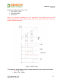
5. Connectors and ports (interfaces)
5.1.
DAEnetIP1 ports
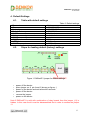
Figure 2. DAEnetIP1 ports
First pin on every pin header group is marked with square at the bottom and with
triangle at the top silk screen.
5.2.
DAEnetIP1 ports description
Table 3. Digital outputs port JP1
Pin N
1
2
3
4
5
6
7
8
9
10
Bit
0
1
2
3
4
5
6
7
-
Function
GPO
GPO
GPO
GPO
GPO
GPO
GPO
GPO
GND
3V3
Direction
OUT
OUT
OUT
OUT
OUT
OUT
OUT
OUT
-
Pin N
1
2
3
4
5
6
7
8
9
1
Bit
0
1
2
3
4
5
6
7
0
Function
GPIO
GPIO
GPIO
GPIO
GPIO
GPIO
GPIO
GPIO
GND
GPIO
Direction
IN/OUT
IN/OUT
IN/OUT
IN/OUT
IN/OUT
IN/OUT
IN/OUT
IN/OUT
IN/OUT
Pull-up
3v3/4k7
3v3/4k7
3v3/4k7
3v3/4k7
3v3/4k7
3v3/4k7
3v3/4k7
3v3/4k7
-
Buffer
100 ohm
100 ohm
100 ohm
100 ohm
100 ohm
100 ohm
100 ohm
100 ohm
-
Table 4. Digital inputs/outputs port JP2
Pull-up
3v3/4k7
3v3/4k7
3v3/4k7
3v3/4k7
3v3/4k7
3v3/4k7
3v3/4k7
3v3/4k7
3v3/4k7
Buffer
100 ohm
100 ohm
100 ohm
100 ohm
100 ohm
100 ohm
100 ohm
100 ohm
100 ohm
-6-
DAEnetIP1 User Manual
17 Jan 2014
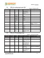
Table 5. Digital outputs port JP3
Pin N
1
2
3
4
5
6
7
8
9
10
Bit
0
1
2
3
-
Function
GPO
GPO
GPO
GPO
PWR_EN
Vin
Vin
GND
GND
GND
Direction
OUT
OUT
OUT
OUT
OUT
OUT
OUT
-
Pin N
Bit
Function
Channel0
Channel1
Channel2
Channel3
Channel4
Channel5
Channel6
Channel7
GND
+2.5V (Vref)
Direction
AIN
AIN
AIN
AIN
AIN
AIN
AIN
AIN
-
Pull-up
3v3/2k2
3v3/2k2
3v3/2k2
3v3/2k2
-
Buffer
-
Table 6. Analog Inputs port JP4
1
2
3
4
5
6
7
8
9
10
0
1
2
3
4
5
6
7
-
Pull-up
-
Buffer
-
Legend:
•
•
•
•
"IN" – the pin is digital input
"OUT" – the pin is digital output
"IN/OUT" – the pin is digital input or output depending the settings
"IN" – analog input
The maximum current for the outputs is 4mA.
-7-
DAEnetIP1 User Manual
17 Jan 2014
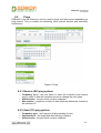
6. Web access
Figure 3. Web access
It is possible to configure DAEnetIP1 via IE, Chrome, Mozilla or other browser.
The browser must support JavaScript and cookies must be enabled. There is
username and password preventing unauthorized login. The http server's port is fixed
- always 80.
-8-
DAEnetIP1 User Manual
17 Jan 2014
6.1.
Digital outputs port JP1
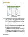
Figure 4. JP1 settings
JP1 is 8 bit digital output port.
• Save – Save current pin settings in the EEPROM. When this parameter
is checked (enabled), this means the states will be saved each time when
they are changed, however because the EEPROM has limit erase/write cycle
count (1 000 000), this is not recommend to be used for fast changing states
applications. See also Switch Delay.
• Pin – JP1 pin number (from 0 up to 7)
• State – Current pin state. Checked - 1 (High Level, 3.3V), not checked - 0
(Low Level, 0V).
• Switch Delay – Delay in seconds for reverts pin state (sec). This is the
delay used for so called hardware pulse function. Must be zero, before
saving pin state!
• Description – Up to 14 symbols description.
After some values are changed, press corresponding button:
• If Initial Delay is with value between 1 and 254 and if the pin state was
changed then the pin will revert in the original state after the defined delay in
seconds.
• If Initial Delay is set, after DAEnetIP1 boot-up the pin will change his
state after the defined delay in seconds.
• Pin with Initial Delay 0, will immediately change its state without revert
to original.
-9-
DAEnetIP1 User Manual
17 Jan 2014
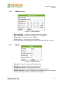
6.2.
Digital inputs/outputs port JP2
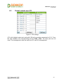
Figure 5. JP2 settings
JP2 is 8 bit digital inputs/outputs port. However via web it is possible to use only the
digital outputs. The digital inputs are accessible only via snmp.
• Save – Save current pin settings in the EEPROM. When this parameter
is checked (enabled), this means the states will be saved each time when
they are changed, however because the EEPROM has limit erase/write cycle
count (1 000 000), this is not recommend to be used for fast changing states
applications. See also Switch Delay.
• Pin – JP1 pin number (from 0 up to 7)
• State – Current pin state. Checked - 1 (High Level, 3.3V), not checked - 0
(Low Level, 0V).
• Switch Delay – Delay in seconds for reverts pin state (sec). This is the
delay used for so called hardware pulse function. Must be zero, before
saving pin state!
• Description – Up to 14 symbols description.
After some values are changed, press corresponding button:
• If Initial Delay is with value between 1 and 254 and if the pin state was
changed then the pin will revert in the original state after the defined delay in
seconds.
• If Initial Delay is set, after DAEnetIP1 boot-up the pin will change his
state after the defined delay in seconds.
• Pin with Initial Delay 0, will immediately change its state without revert
to original.
-10-
DAEnetIP1 User Manual
17 Jan 2014
6.3.
Digital outputs port JP3
Figure 6. JP3 settings
JP3 is 4 bit digital output port each with 2.2K pull-up resistor connected to 3.3V. From
the web interface, the corresponding pins are Pin0 - Pin3. The other pins are not
used. The management rules are same as JP1 and JP2 management.
-11-
DAEnetIP1 User Manual
17 Jan 2014
6.4.
Analog inputs port JP4
Figure 7. JP4 settings
DAEnetIP1 have 8 channel ADC port (JP4) with 2.5VDC refferent voltage. Each ADC
channel has 1 MOhm pull-down resistor connected to GND:
• Curr - current value measured from the channel (0 to 1023)
• Refresh - read frequency (1=100ms)
• Threshold (low/high) - low/high voltage limits
• Hysteresis (low/high) - voltage hysteresis
• Mode
o Low - the measured value under LT (low threshold) digital output
becomes 0. Over it - 1.
o High - the measured value under HT (high threshold) digital output
becomes 1. Over it - 0.
o Low/High - the measured value under LT digital output becomes 0.
Between LT and HT - 1. Over HT - 0.
o Acc - the measured value falls under LT, digital output becomes 0.
Digital output becomes 1 above HT.
• SNMP trap - Sends SNMP trap when state changes with current value.
• To JP1 - Depends from the mode, changes reflects over JP1.
• To JP2 - Depends from the mode, changes reflects over JP2.
• To JP3 - Depends from the mode, changes reflects over JP3.
• Description - channel description.
Valid values:
• Refresh - from 0 to 255.
o 0 - don't read from the channel
o 10 - read every second
o 255 - don't read from the channel
• Threshold (Low/High) - from 0 to 1023
• Hysteresis (Low/High) - from 0 to 255
-12-
DAEnetIP1 User Manual
17 Jan 2014
Required conditions for proper work:
1. (HT-HH)>(LT+LH)
2. (HT+HH)<1023
3. (LT-LH)>0
When the required conditions are not performed, the refresh value will be
automatically set to 0. The refresh value must be set greater than zero, when the
proper conditions are filled.
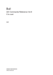
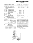
Figure 8. ADC modes
The schematic shows digital outputs change depends from the mode and direction:
• red – high to low
• black – low to high
-13-
DAEnetIP1 User Manual
17 Jan 2014
6.5.
Pings
DAEnetIP1 has the feature to send or receive pings and take actions depending on
ping timeout. This is suitable for monitoring other network devices and eventually
restart them.
Figure 9. Pings
6.5.1.Receive (RX) ping options
•
•
•
Frequency (sec) - the time frame in which the controller must receive
ping in order to clear the counters and not to change the relay state
Affected pins - the pins which must be restarted
Max actions - maximum number of state switching before the function to
be switched off
6.5.2.Send (TX) ping options
•
•
•
Frequency (sec) - the frequency of ping sending (in sec)
Destination IP - the target host that the ping is send to
Affected pins - the pins which must be restarted
-14-
DAEnetIP1 User Manual
17 Jan 2014
•
•
•
Rules:
•
•
•
•
•
•
6.6.
Max Actions - maximum number of state changing before the function to
be turned off
Loses for action - it determines on how many lost packets there will be
state changing
Frame size - size of the sent packet
Each pressing of the button "Apply" resets the counters.
To disable the functions a 0 must be filled into the "Frequency" filed
If the value is > 0 and <255 then the functions are activated
The "Switch delay" parameter in JP1, JP2 or JP3 sections must be >0 in
order to be affected by the functions
If the "Switch delay" parameter of JP1, JP2 or JP3 is 0, then this (these)
pins are not affected
Function with status "Blocked" can be reactivated only if the button
"Apply" is pressed or it is appeared the condition (received ECHO REPLY
or ECHO depending the section).
System settings
Figure 10. System settings
•
•
•
•
•
•
IP Address – DAEnetIP1 IP address
Subnet Mask – DAEnetIP1 network mask
Default Gateway – DAEnetIP1 default gateway address
802.1Q – 802.1Q mode on or off
DHCP Client – DHCP client enable/disable
VID – 802.1Q VLAN tag
When only DHCP client mode is disabled, full restart procedure (around 10
seconds) will occure.
-15-
DAEnetIP1 User Manual
17 Jan 2014
6.7.
SNMP access
Figure 11. SNMP settings
•
•
•
•
•
6.8.
RO community – read-only community (max. 14 symbols)
RW community – read-write settings (max. 14 symbols)
Trap server 1 – First trap server address.
Trap server 2 – Second trap server address
If you don’t want to use trap server make it 255.255.255.255 or 0.0.0.0
Admin
Figure 12. Admin settings
•
•
•
•
•
Username – Admin username (8 symbols max)
Password – Admin password (16 symbols max)
Re-enter password – Admin password check
Snmp port - the port for the snmp server (by default it is 161)
Inverse selection - inverse the states of the digital outputs (it is because
some of our relay boards are with reverse TTL logic)
-16-
DAEnetIP1 User Manual
17 Jan 2014
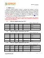
7. SNMP access
DAEnetIP1 supports SNMPv1 protocol – snmpget and snmpset. It may be
configured/read all the parameters via these commands. Read-only community string
is used for reading and Read-Write Community String is used for changing the
parameters. Note that it is not possible using of snmpwalk. Parameters that can be
changed, are grouped according to their functions in the tables below. To obtain a
valid OID number it is necessary to replace the “x” symbol with the prefix
”.1.3.6.1.4.1.32111”. Also all the snmp commands are described in the MIB file. All
the functions can be accessed via SNMP and WEB
IMPORTANT! During SNMP access, it must be used snmpget and snmpset
only to one OID and not to group of OIDs. Other commands (snmpwalk for
instance) are not supported.
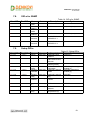
7.1.
Start OID
OID-s for digital output port JP1
Name
Access
x.1.1.1.1
x.1.1.1.8
JP1Save
read-write
Save states for JP1
x.1.1.2.1
x.1.1.2.8
JP1State
read-write
Control JP1 State
x.1.1.3.1
x.1.1.4.1
x.1.1.3.8
x.1.1.4.8
JP1Delay
JP1Descri
ption
read-write
read-write
Switch delay for JP1
JP1 description
7.2.
Start OID
End OID
Table 7. OID-s for JP1
Description
Syntax
INTEGER { High(1),
Low(0) }
INTEGER { High(1),
Low(0) }
INTEGER (0..255)
STRING (0..14)
OID-s for digital input/output port JP2
End OID
Name
Access
Description
Table 8. OID-s for JP2
Syntax
x.1.6.1.1
x.1.6.1.8
JP2Save
read-write
Save states for JP2
x.1.6.2.1
x.1.6.2.8
JP2State
read-write
Control JP2 State
x.1.6.3.1
x.1.6.4.1
x.1.6.3.8
x.1.6.4.8
read-write
read-write
Switch delay for JP2
JP2 description
x.1.6.5.1
x.1.6.4.8
JP2Delay
JP2Descri
ption
JP2Value
INTEGER { High(1),
Low(0) }
INTEGER { High(1),
Low(0) }
INTEGER (0..255)
STRING (0..14)
read-only
The value for the
digital input JP2
INTEGER { High(1),
Low(0) }
7.3.
Start OID
OID-s for digital input/output port JP3
End OID
Table 9. OID-s for JP3
Description
Syntax
Name
Access
x.1.4.1.1
x.1.4.1.4
JP3Save
read-write
Save states for JP3
x.1.4.2.1
x.1.4.2.4
JP3State
read-write
Control JP3 State
x.1.4.3.1
x.1.4.4.1
x.1.4.3.4
x.1.4.4.4
JP3Delay
JP3Descri
ption
read-write
read-write
Switch delay for JP3
JP3 description
INTEGER { High(1),
Low(0) }
INTEGER { High(1),
Low(0) }
INTEGER (0..255)
STRING (0..14)
-17-
DAEnetIP1 User Manual
17 Jan 2014
7.4.
Start OID
OID-s for analog input port JP4
End OID
Name
Access
x.1.5.1.1
x.1.5.1.8
JP4Value
read-only
x.1.5.2.1
x.1.5.2.8
JP4Refre
sh
read-write
x.1.5.3.1
x.1.5.3.8
read-write
x.1.5.4.1
x.1.5.4.8
x.1.5.5.1
x.1.5.5.8
x.1.5.6.1
x.1.5.6.8
x.1.5.7.1
x.1.5.7.8
x.1.5.8.1
x.1.5.8.8
JP4LowT
hreshold
JP4HighT
hreshold
JP4LowH
ysteresis
JP4HighH
ysteresis
JP4Descri
ption
JP4Mode
x.1.5.9.1
x.1.5.9.8
x.1.5.10.1
x.1.5.10.8
x.1.5.11.1
x.1.5.11.8
x.1.5.12.1
x.1.5.12.8
JP4SNMP
Trap
JP4MapT
oJP1
JP4MapT
oJP3
JP4MapT
oJP2
7.5.
Start OID
Table 10. OID-s for JP4
Description
Syntax
JP4 Value of the
ADC channel
Refresh time, one
unit is equal to
100ms
Low threshold Value
INTEGER ( 0..1023)
INTEGER (0..1023)
read-write
High threshold
Value
Low hysteresis
Value
High hysteresis
Value
JP4 Description
read-write
Operating JP4 Mode
read-write
Send SNMP trap on
event
Activate JP1 on
event
Activate JP3 on
event
Activate JP2 on
event if it is digital
output
INTEGER {Low(0),
High(1), LowHigh(2),
Acc(3)}
INTEGER {no(0), yes(1)}
read-write
read-write
read-write
read-write
read-write
read-write
INTEGER (0..255)
INTEGER (0..1023)
INTEGER (0..1023)
INTEGER (0..1023)
STRING (0..14)
INTEGER {no(0), yes(1)}
INTEGER {no(0), yes(1)}
INTEGER {no(0), yes(1)}
OID-s for TX (sending) pings
Name
Access
x.1.2.1.1
x.1.2.1.2
x.1.2.1.3
x.1.2.1.1
x.1.2.1.2
x.1.2.1.3
End OID
txFreq
txIP
txToJP1
read-write
read-write
read-write
x.1.2.1.4
x.1.2.1.4
txMax
read-write
x.1.2.1.5
x.1.2.1.5
txAction
read-write
x.1.2.1.6
x.1.2.1.7
x.1.2.1.6
x.1.2.1.7
txMaxLen
txStatus
read-write
read-only
x.1.2.1.8
x.1.2.1.8
txLost
read-only
x.1.2.1.9
x.1.2.1.9
txCount
read-only
Table 11. OID-s for TX pings
Description
Syntax
TX ping frequency
TX IP address
Affected JP1 pins in
decimal for TX pings
Maximum reply lost
before action to be
taken
Maximum MAX
counts before the
service become in
BLOCKED state
IP packet len
An actual status of
the txPing
functionality
Number of seconds
non-received ICMP
ECHO REPLY
packets
Number of actions
INTEGER (0..255)
IpAddress
INTEGER (0..255)
INTEGER (0..255)
INTEGER (0..255)
INTEGER (64..1400)
INTEGER {Blocked(0),
InService(1), Disabled(2)}
INTEGER (0..255)
INTEGER (0..255)
-18-
DAEnetIP1 User Manual
17 Jan 2014
x.1.2.1.10
x.1.2.1.11
x.1.2.1.10
x.1.2.1.11
txDelay
txToJP3
read-only
read-write
x.1.2.1.13
x.1.2.1.13
txToJP2
read-write
7.6.
Start OID
End OID
Name
Access
x.1.2.2.1
x.1.2.2.2
rxFreq
rxToJP1
read-write
read-write
x.1.2.2.3
x.1.2.2.3
rxMax
read-write
x.1.2.2.4
x.1.2.2.4
rxStatus
read-only
x.1.2.2.5
x.1.2.2.5
rxLost
read-only
x.1.2.2.6
x.1.2.2.6
rxCount
read-only
x.1.2.2.7
x.1.2.2.7
rxToJP3
read-write
x.1.2.2.8
x.1.2.2.8
rxToJP2
read-write
Start OID
INTEGER (0..255)
INTEGER (0..255)
INTEGER (0..255)
OID-s for TX (sending) pings
x.1.2.2.1
x.1.2.2.2
7.7.
taken after txFreq is
reached
ICMP ping Delay
Affected JP3 pins in
decimal for TX pings
Affected JP2 pins in
decimal for TX pings
Table 12. OID-s for RX pings
Description
Syntax
RX ping frequency
Affected JP1 pins in
decimal for RX pings
Maximum request
lost before action to
be taken
An actual status of
the rxPing
functionality
Number of seconds
non-received ICMP
ECHO packets
Number of actions
taken after rxFreq is
reached
Affected JP3 pins in
decimal for RX pings
Affected JP2 pins in
decimal for RX pings
INTEGER (0..255)
INTEGER (0..255)
INTEGER (0..255)
INTEGER {Blocked(0),
InService(1), Disabled(2)}
INTEGER (0..255)
INTEGER (0..255)
INTEGER (0..255)
INTEGER (0..255)
OID-s for TFTP
End OID
Name
Access
x.1.3.1.1
x.1.3.1.1
tftpIP
read-write
x.1.3.1.2
x.1.3.1.3
x.1.3.1.2
x.1.3.1.3
tftpFile
tftpVer
read-write
read-only
x.1.3.1.4
x.1.3.1.4
tftpConfir
m
read-write
Table 13. OID-s for TFTP
Description
Syntax
TFTP server IP
address
Requested file
Current loaded
firmware version
start TFTP session
read-write
read-write
read-only
read-write
-19-
DAEnetIP1 User Manual
17 Jan 2014
7.8.
Start OID
OID-s for SNMP
End OID
x.1.3.2.3.0
x.1.3.2.3.0
x.1.3.2.4.0
x.1.3.2.4.0
x.1.3.2.5.0
x.1.3.2.5.0
x.1.3.2.6.0
x.1.3.2.6.0
x.1.3.2.7.0
x.1.3.2.7.0
x.1.3.2.8.0
x.1.3.2.8.0
7.9.
Start OID
Table 14. OID-s for SNMP
Description
Syntax
Name
Access
SNMPacc
essIP1
SNMPacc
essNET1
SNMPacc
essIP2
SNMPacc
essNET2
SNMPTra
pServerIP
1
SNMPTra
pServerIP
2
read-write
SNMP Access IP 1
IpAddress
read-write
SNMP Access net 1
INTEGER (0..32)
read-write
SNMP Access IP 2
IpAddress
read-write
SNMP Access net 2
INTEGER (0..32)
read-write
SNMP TRAP
SERVER IP 1
IpAddress
read-write
SNMP TRAP
SERVER IP 2
IpAddress
Setup OID-s
End OID
Name
Access
x.1.3.4.1
x.1.3.4.1
setupIP
read-write
x.1.3.4.2
x.1.3.4.2
setupMas
k
read-write
x.1.3.4.3
x.1.3.4.3
setupGW
read-write
x.1.3.4.4
x.1.3.4.4
read-write
x.1.3.4.5
x.1.3.4.5
x.1.3.4.6
x.1.3.4.6
x.1.3.4.7
x.1.3.4.7
x.1.3.4.8
x.1.3.4.8
x.1.3.4.9
x.1.3.4.9
x.1.3.4.10
x.1.3.4.10
setupDHC
Pclient
setup802
1QJP4Mo
de
setup802
1Qtag
setupFirm
wareNam
e
setupRest
art
setupMA
C
setupPCB
Temp
Table 15. Setup OID-s
Description
Syntax
DAEnetIP1 IPv4
Address
DAEnetIP1 IPv4
NET MASK dotted
decimal
DAEnetIP1 IPv4
Default gateway
DAEnetIP1 DHCP
client state
DAEnetIP1 802.1Q
Mode
IpAddress
DAEnetIP1 802.1Q
tag
DAEnetIP1 firmware
version
INTEGER
write-only
DAEnetIP1 restart
INTEGER
read-only
DAEnetIP1 MAC
address
DAEnetIP1 on board
temperature (C)
STRING
read-write
read-write
read-only
read-only
IpAddress
IpAddress
INTEGER {disabled(0),
enabled(1)}
INTEGER {disabled(0),
enabled(1)}
STRING (0..14)
STRING
-20-
DAEnetIP1 User Manual
17 Jan 2014
8. Appendix 1. Power supply
•
•
Power supply: DC 12 V
200 mA (stabilized and filtered)
Controller consumption: 117mA/12V DC
GND
(NEGATIVE)
+12VDC
Figure 13. Power jack
Figure 14. Location of the power jack
•
Polarity: Center positive, the inner pin of the power supply adaptor jack
must be +12VDC.
+
-
Figure 15 Polarity
•
Before using the power supply, measure the output voltage with
voltmeter. The output voltage must be 12V DC +/- 5%
CORRECT 12.00V
WRONG -12.00V
RED
RED
V
COM
V
COM
BLACK
BLACK
Figure 16. Correct polarity
Note that DAEnetIP1 does not have reverse polarity protection. Power
supply with different polarity shown in this document will damage the device.
DAEnetIP1 connection to the Ethernet network is done with UTP Cat.5 cable with
RJ45 connector. 10 seconds after power on, the device is ready for work.
-21-
DAEnetIP1 User Manual
17 Jan 2014
9. Appendix 2. DAEnetIP1 installation
9.1.
Connect DAEnetIP1 to computer for first time
1. Connect your DAEnetIP1 controller (or kit) with UTP cable.
2. Connect the PC with the other end of this cable
3. Check out carefully that there is not danger of short cuts or metal surface
around the controller
4. If there are additional wires from the DAEnetIP1 controller connect them (to
the relay board or any other device) first
5. Check out the power supply you will use for DAEnetIP1 if it is correct
according this document
6. Plug in the DC jack from the power adaptor to the device DC plug
7. TURN ON the power supply source
8. The power led (red one) must be on
9. The DAEnetIP1 needs about 10 seconds to boot
10. Adjust your PC IP to be 192.168.0.1
11. Access the device via Web browser - type its IP in the url address line
(192.168.0.100) in the address bar and use admin / admin for username /
password
9.2.
Connect DAEnetIP1 to router
1. We assume you have PC IP - 192.168.1.2, Router IP - 192.168.1.1 and
DAEnetIP1 factory IP - 192.168.0.100
2. Connect your DAEnetIP1 controller (or kit) with UTP cable.
3. Connect the PC with the other end of this cable.
4. Plug the DC jack from the power adaptor to the device DC plug.
5. TURN ON the power supply source.
6. The power led (red one) must be on
7. The DAEnetIP1 needs about 10 seconds to boot
8. Adjust your PC IP to be 192.168.0.1
9. Access the device via Web browser - type its IP (192.168.0.100) in the
address bar and use admin / admin for username / password.
10. Change the DAEnetIP1 IP to be 192.168.1.3 (to mach your network).
11. Change back the old IP of your PC - 192.168.1.2
12. Turn off the DAEnetIP1 controller
13. Unplug the UTP cable from PC and conect it to router.
14. Power on the DAEnetIP1 controller
15. Type in browser 192.168.1.3 ( the new IP) and access the controller.
-22-
DAEnetIP1 User Manual
17 Jan 2014
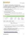
10.
Appendix 3. Port forwarding - for advanced users
This appendix describes how to access the DAEnetIP1 over the Internet. The
demonstration is done with router "TP-Link TL-WR340G", but it may be done with
any other router supporting "Port Forwarding" function. Bellow are given the steps
you have to go through to make "Port Forwarding".
1. Adjust DAEnetIP1 network ports (the INTERNAL PORTS). These ports are:
• SNMP port - by default 161.
• HTTP port 80 (can not be changed)
Let's say we would like to adjust for example:
• Port 10161 for SNMP
This may easily be done from the DAEnetIP1 web server -> Admin page
2. These ports must be set in the forwarding rules inside the router as it is shown
on the figure bellow
Figure 17. Port forwarding
The IP address 192.168.1.11 is actually the internal address of the DAEnetIP1.
3. Now it is possible to access the DAEnetIP1 from everywhere outside the LAN
(including over the Internet).
xxx.xxx.xxx.xxx:10080 - is the web server of the module
snmpget -v1 -c 000000000000 xxx.xxx.xxx.xxx:10161 .1.3.6.1.4.1.32111.1.3.4.1 snmp command for accessing the module (get the IP)
xxx.xxx.xxx.xxx - the public IP of the router or it's DNS name.
Good online guide for port-forwarding is the bellow link:
http://portforward.com/english/routers/port_forwarding/
-23-
DAEnetIP1 User Manual
17 Jan 2014
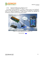
11.
Appendix 4. Software
11.1.
DAEnetIP1 Manager
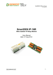
Figure 18. DAEnetIP1 Manager
DAEnetIP1 Manager is simple SNMP utility designed especially for DAEnetIP1. It is
java based software and it is suitable for Windows, Linux and MAC. The software has
it's own web page and it is described here:
http://denkovi.com/page/18/daenetip1-manager.html
-24-
DAEnetIP1 User Manual
17 Jan 2014
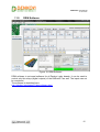
11.2.
DRM Software
Figure 19. DRM Software
DRM software is universal software for all Denkovi relay boards. It can be used to
control only the relays (digital outputs) of the DAEnetIP1 as well. The inputs can not
be monitored.
The software is described here:
http://denkovi.com/page/13/drm-software.html
-25-
DAEnetIP1 User Manual
17 Jan 2014
11.3.
Android Software by iSwitch, LLC
The featured Android application is offered to extend control of the DAEnetIP1
controller and relay board to your Android phone. This application is designed to
work on an Android Smartphone or Tablet, however screens are optimized for
Smartphones. Please note this is third parity software.
Figure 20. Android application from iSwitch, LLC
Download link - here
-26-
DAEnetIP1 User Manual
17 Jan 2014
11.4.
Control from command line
11.4.1. Windows
Net-snmp is command line tool for accessing SNMP based network devices under
windows console. By default it is not included in Windows OS. DAEnetIP1 can be
easily accessed by the net-snmp tool. This is very useful when the snmp commands
must be executed from batch file for example.
Bellow are the steps for installing net-snmp tool on windows OS.
• Download the last version net-snmp binary for windows from http://netsnmp.sourceforge.net/download. The file must look like net-snmp-X.X.X.XX.win32.exe
• Install the downloaded file. Leave the default options. The packet will be install
in c:\usr by default.
• Download the DAEnetIP1 MIB file from here file.
• Copy the mib file here c:\usr\share\snmp\mibs
• Add new line in the file c:\usr\etc\snmp\snmp.conf with the "mibs all" directive.
• Now you can test different commands for OID access, supported by this
module. Their names you may see in the DAEnetIP1 .mib file.
A simple test may be done to be sure if the tool is installed successfully:
run->cmd->
snmpget -v1 -c 000000000000 192.168.0.100 . 1.3.6.1.4.1.32111.1.3.4.1
For creating batch files, you may use the following steps for example which turns
on the JP1 digital output 1 for 5 seconds and then turn it off:
• Open new file and save it as ON.bat
• Enter the following code:
snmpset -v1 -c private 192.168.0.100 .1.3.6.1.4.1.32111.1.1.1.1 i 0
PING 1.1.1.1 -n 1 -w 5000
snmpset -v1 -c private 192.168.0.100 .1.3.6.1.4.1.32111.1.1.1.1 i 1
• Save the file
• Run it.
-27-
DAEnetIP1 User Manual
17 Jan 2014
11.4.2. Linux
Usually most of Linux OS come with snmp tool installed.
1. To check out if snmp is installed, just open one terminal and type:
snmpget -v1 -c 000000000000 192.168.0.100 .1.3.6.1.4.1.32111.1.3.4.1
(Ofcourse with your network settings)
If you get some message like this: "snmp is not function" or "snmp not found", it
seems that snmp is not installed and you have to follow the hints that the command
line gives you. After that repeat step 1.
2. Create bash file for example ON.vim and enter the following commands in it:
#!/bin/bash
snmpset -v1 -c private 192.168.0.100 .1.3.6.1.4.1.32111.1.1.1.1 i 0
sleep 5s
snmpset -v1 -c private 192.168.0.100 .1.3.6.1.4.1.32111.1.1.1.1 i 1
3. Save the file
4. Run it.
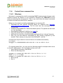
11.4.3. SNMPGET example commands
Get JP1 pin1 State - This will read digital output JP1.1 state
snmpget -v1 -c private 192.168.0.100 .1.3.6.1.4.1.32111.1.1.1.1
Get JP1 pin8 State - This will read digital output JP1.8 state
snmpget -v1 -c private 192.168.0.100 .1.3.6.1.4.1.32111.1.1.1.8
Get JP2 pin1 State - This will read digital output JP2.1 state
snmpget -v1 -c private 192.168.0.100 .1.3.6.1.4.1.32111.1.6.2.1
Get JP2 pin8 State - This will read digital output JP2.8 state
snmpget -v1 -c private 192.168.0.100 .1.3.6.1.4.1.32111.1.6.2.8
Get JP2 pin1 Value - This will read digital input JP2.1 value
snmpget -v1 -c private 192.168.0.100 .1.3.6.1.4.1.32111.1.6.5.1
Get JP2 pin8 Value - This will read digital input JP2.8 value
snmpget -v1 -c private 192.168.0.100 .1.3.6.1.4.1.32111.1.6.5.8
Get JP3 pin1 State - This will read digital output JP3.1 state
snmpget -v1 -c private 192.168.0.100 .1.3.6.1.4.1.32111.1.4.2.1
Get JP3 pin4 State - This will read digital output JP3.4 state
snmpget -v1 -c private 192.168.0.100 .1.3.6.1.4.1.32111.1.4.2.4
-28-
DAEnetIP1 User Manual
17 Jan 2014
Get JP4 pin1 Value - This will read analog input JP4.1 value
snmpget -v1 -c private 192.168.0.100 .1.3.6.1.4.1.32111.1.5.1.1
Get JP4 pin8 Value - This will read analog input JP4.8 value
snmpget -v1 -c private 192.168.0.100 .1.3.6.1.4.1.32111.1.5.1.8
Get the MAC Address
snmpget -v1 -c private 192.168.0.100 .1.3.6.1.4.1.32111.1.3.4.9
Get the IP Address
snmpget -v1 -c private 192.168.0.100 .1.3.6.1.4.1.32111.1.3.4.1
Get the internal temperature sensor value
snmpget -v1 -c private 192.168.0.100 .1.3.6.1.4.1.32111.1.3.4.10
11.4.4. SNMPSET example commands
Set JP1 pin1 State - This will set digital output JP1.1 state in high level
snmpset -v1 -c private 192.168.0.100 .1.3.6.1.4.1.32111.1.1.1.1 i 1
Set JP1 pin8 State - This will set digital output JP1.8 state in low level
snmpset -v1 -c private 192.168.0.100 .1.3.6.1.4.1.32111.1.1.1.8 i 0
Set JP2 pin1 State - This will set digital output JP2.1 state in high level
snmpset -v1 -c private 192.168.0.100 .1.3.6.1.4.1.32111.1.6.2.1 i 1
Set JP2 pin8 State - This will set digital output JP2.8 state in low level
snmpset -v1 -c private 192.168.0.100 .1.3.6.1.4.1.32111.1.6.2.8 i 0
Set JP3 pin1 State - This will set digital output JP3.1 state in high level
snmpset -v1 -c private 192.168.0.100 .1.3.6.1.4.1.32111.1.4.2.1 i 1
Set JP3 pin4 State - This will set digital output JP3.4 state in low level
snmpset -v1 -c private 192.168.0.100 .1.3.6.1.4.1.32111.1.4.2.4 i 0
-29-
DAEnetIP1 User Manual
17 Jan 2014
12.
Appendix 5. Software examples
Software examples can be found on this link
-30-
DAEnetIP1 User Manual
17 Jan 2014
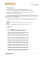
13.
Appendix 6. Firmware upgrade
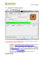
13.1.
Via DAEnetIP Burner
Figure 21. DAEnetIP Burner
It is recommend to use DAEnetIP Burner for TFTP firmware upgrade of
DAEnetIP1! It is the easiest and safer way!
•
•
•
•
Download and install DAEnetIP Burner. Software for firmware upgrade of
DAEnetIP1 - http://denkovi.com/page/31/daenetip-burner.html
Download and save the version you need for upgrading the DAEnetIP1
controller.
The
binary
(.bin)
file
must
be
downloaded
from www.denkovi.com. It may be downloaded from the link in the
application or directly from this link. Support for firmware file also may be
received by e-mail [email protected].
Navigate the application to this file by clicking button with label “…”.
From the Device list select DAEnetIP1.
-31-
DAEnetIP1 User Manual
17 Jan 2014
•
•
•
•
•
•
•
•
•
In the IP address field type the IP address of the target DAEnetIP1
controller that must be upgraded.
In the Port field type the port on that DAEnetIP1 can be reached. This is
the SNMP port. Ususally it is 161 (by default)
In the Password field type the SNMP password used in this DAEnetIP1
controller (default is "private").
Check if the settings are correct by clicking button “Check device”. After
successful connection under this button it must appears text with the
DAEnetIP1 version. If this not happens it means the connection is not
successful and you must repeat again steps 3-6.
Set the TFTP Server. This is usually the computer IP address that will be
used as TFTP server.
Set the maximum retries field. This field shows how many times
the DAEnetIP Burner will try to reconnect with the DAEnetIP1 controller if
the connection is lost for a moment. A value of 5-10 is reasonable.
Start update by clicking Burn button. If everything is correct, a new line
must appear in the event log and the progress bar must starts moving
on.
Wait until the file is uploaded. This will be indicated when the New
version field is not ??? but some value – form example 1.50. Then
the Status field must be with value “File is uploaded successfully”.
Your DAEnetIP1 controller is upgraded successfully with the desired
firmware version. Now when you click button “Check device”, the new
version must appear.
-32-
DAEnetIP1 User Manual
17 Jan 2014
13.2.
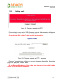
Via http (web)
Figure 22. Firmware upgrade via HTTP
From navigation menu select "WEB firmware upgrade". Above warning will appear
on the screen. For confirmation, press "Update" button.
Currently, only IE 6 or later is able use this update option.
Figure 23. Firmware upgrade via HTTP - progress
Pressing "Browse" button, will give you a choice between different files. Select the
proper one and press "Update" button.
Warning!!!
Do not power off the device. If the update was interrupted, you could find the
device on his last known IP address.
-33-
DAEnetIP1 User Manual
17 Jan 2014
13.3.
TFTP via WEB
Figure 24. TFTP via web
• IP address – TFTP server address
• Filename – Firmware file name
• Firmware Version – Currently installed firmware version
• Confirm upgrade – The checkbox must be checked before press
"Update"
• Button "Update" starts the firmware upgrade procedure.
-34-
DAEnetIP1 User Manual
17 Jan 2014
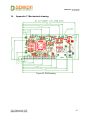
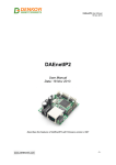
14.
Appendix 7. Mechanical drawing
Figure 25. PCB drawing
-35-