1
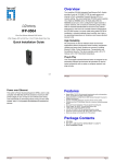
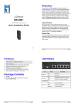
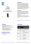
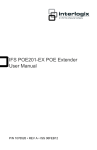
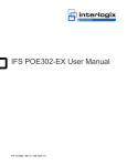
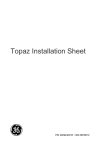
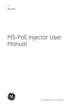
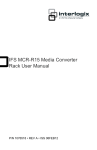
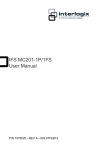
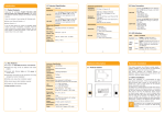
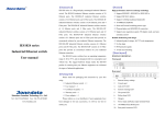
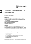
IFS POE302-MS Ethernet Injector
User Manual
P/N 1076517 • REV A • ISS 08FEB12
Copyright
Trademarks and
patents
Manufacturer
Version
Certification
FCC compliance
ACMA
compliance
European Union
directives
© 2012 UTC Fire & Security Company. All rights
reserved.
Interlogix, IFS POE302-MS Ethernet Injector, the
IFS Brand and logo are trademarks of
UTC Fire & Security.
Other trade names used in this document may be
trademarks or registered trademarks of the
manufacturers or vendors of the respective
products.
UTC Fire & Security Americas Corporation, Inc.
2955 Red Hill Avenue, Costa Mesa, CA
92626-5923, USA
This document applies to IFS POE302-MS
Ethernet Injector version 1.0.
N4131
Class A: This equipment has been tested and
found to comply with the limits for a Class A digital
device, pursuant to part 15 of the FCC Rules.
These limits are designed to provide reasonable
protection against harmful interference when the
equipment is operated in a commercial
environment. This equipment generates, uses,
and can radiate radio frequency energy and, if not
installed and used in accordance with the
instruction manual, may cause harmful
interference to radio communications. Operation
of this equipment in a residential area is likely to
cause harmful interference in which case the user
will be required to correct the interference at his
own expense.
Notice! This is a Class A product. In a domestic
environment this product may cause radio
interference in which case the user may be
required to take adequate measures.
2004/108/EC (EMC directive): Hereby, UTC Fire
& Security declares that this device is in
compliance with the essential requirements and
other relevant provisions of Directive 2004/108/EC
2002/96/EC (WEEE directive): Products marked
with this symbol cannot be disposed of as
unsorted municipal waste in the European Union.
For proper recycling, return this product to your
local supplier upon the purchase of equivalent
new equipment, or dispose of it at designated
collection points. For more information see:
www.recyclethis.info.
Contact
information
Customer support
www.utcfireandsecurity.com or
www.interlogix.com
www.interlogix.com/customer-support
Contents
Package Contents 1
Product Features 1
Interface 1
PoE 1
Hardware 2
Standard Compliance 2
Product Overview 3
LED Indicators 3
Hardware Installation 3
Before Installation 3
Injector Installation 4
Injector and Splitter Installation 5
Specifications 7
Contacting Technical Support 8
IFS POE302-MS Ethernet Injector User Manual
i
Package Contents
Thank you for purchasing the IFS POE302-MS, an IEEE
802.3at High Power over Ethernet Injector.
Open the package containing the Ethernet Splitter and
carefully unpack it. The box should contain the following items:
● POE302-MS x1
● User Manual x1
● Power Cord x 1
If any of these items are missing or damaged, please contact
your Interlogix reseller. If possible, retain the original carton
and packaging material and use them again to repack the
product in case there is a need to return it to us for repair.
Product Features
Interface
•
•
2-Port RJ-45 interfaces
•
1-Port PoE Power + Data output
•
1-Port Data input
1 56V DC input power socket
PoE
•
High Power over Gigabit Ethernet Mid-Span PSE
•
IEEE 802.3at PoE compliant
•
IEEE 802.3af devices compatible
•
One IEEE 802.3at device can be powered
•
Provides 56VDC power to the RJ-45 Ethernet port
IFS POE302-MS Ethernet Injector User Manual
1
•
Auto-detection of POE IEEE 802.3at equipment and
devices to prevent damage caused by incorrect installation
•
Remote power feeding of up to 328 ft. (100m)
Hardware
•
Metal Enclosure
•
LED indicators for Power and PoE in-use
Standard Compliance
•
IEEE 802.3 10Base-T
•
IEEE 802.3u 100Base-TX
•
IEEE 802.3ab 1000Base-T
•
IEEE 802.3at Power over Ethernet
•
FCC Part 15 Class A, CE
Note: PSE (Power Sourcing Equipment) is a device (switch or
hub for instance) that will provide power in a PoE setup. The
maximum allowed continuous output power per such device
per the IEEE802.3 at standard is 30 Watts.
PD (Powered Device) is a PoE-enabled device powered by
PSE and thus consumes energy, such as an IP camera, IP
access control, IP intercom, VoIP and wireless access points
(WAP), etc.
2
IFS POE302-MS Ethernet Injector User Manual
Product Overview
Figure 1 shows the front and side panels of the POE302-MS.
Figure 1: POE302-MS Front and Side Panels
LED Indicators
POE302-MS LED indicators
LED
Color
PWR
Green
PoE In-use
Green
Function
Lit indicates that the POE302-MS has power.
Lit indicates that the PoE port is providing 56VDC in-line
power.
Hardware Installation
The POE302-MS operates at three different data rates –
10Mbps, 100Mbps and 1000Mbps in the same device and
automatically adjusts to the data rate of the incoming
transmission.
Before Installation
The POE302-MS requires an external 56VDC power supply to
inject DC power onto the pins of the twisted pair cable (pair 4,
5 and pair 7, 8).
IFS POE302-MS Ethernet Injector User Manual
3
Injector Installation
1. Connect the external power adaptor to the 56 VDC power
connector of the POE302-MS. The power LED will be on in
a steady state. (External power adapter is sold separately.)
2. Connect a standard network cable from the non-PoE
switch or other network device to the “Ethernet” port of the
POE302-MS.
3. Connect the long cable that will be used to connect to the
remote POE PD device to the port “Ethernet + DC”.
4. Complying with the IEEE 802.3at Power over Ethernet
standard, the POE302-MS can directly connect with any
IEEE 802.3at end-nodes such as PTZ (Pan, Tilt & Zoom)
network cameras, PTZ Speed Domes, color touch- screen
Voice over IP (VoIP) telephones, and multi- channel
wireless LAN access points that support IEEE 802.3af Inline Power over Ethernet on their ports. Figure 2 shows a
typical application.
Figure 2: Connection Schematic
Once the POE302-MS detects the existence of an IEEE
802.3at device, the PoE in-use LED indicator will be on in a
steady state to show it is providing power.
Note: If the connected device is not fully compliant with the
IEEE 802.3at Power over Ethernet standard or in-line power
device, the LED indicator of the POE302-MS will not remain lit.
4
IFS POE302-MS Ethernet Injector User Manual
Injector and Splitter Installation
1. Connect the external power adaptor to the 56 VDC power
connector of the POE302-MS. The power LED will be lit.
2. Connect a standard network cable from the “Ethernet+DC”
port of the POE302-MS to the “PoE In” port of the POE302SP. The POE In-use LED of POE302-MS / POE302-SP will
remain lit showing operation.
3. Connect a standard network cable from the non-PoE
switch or other network device to the “Ethernet” port of
POE302-MS.
4. Select either 12VDC or 24VDC on the DC power output
switch and then connect the DC plug from "DC Out" of the
POE302-SP to the remote device.
5. Adjust proper DC power output and connect DC plug from
"DC OUT" of POE302-SP to remote device.
6. Power on the remote device and its power LED indicator
will remains on. Remote device will be powered upon
completion of the previous steps.
Figure 3: Injector and Splitter connection
Note: According to the IEEE 802.3at Power over Ethernet
standard the POE302-MS will not inject power to the cable if it
is not connected to IEEE 802.3at devices.
IFS POE302-MS Ethernet Injector User Manual
5
WARNING: Please ensure the output voltage is set correctly
before applying power to remote device.
Note: POE302-MS and POE302-SP can be installed in pairs.
However, use of a third-party device is allowed if the device
complies with IEEE 802.3at Power over Ethernet standard.
6
IFS POE302-MS Ethernet Injector User Manual
Specifications
Ethernet
Data Rate
10/100/1000Mbps
Throughput (packet per second)
148810pps@64Bytes
IEEE Standards
IEEE 802.3 10Base T
IEEE 802.3u 1000Base-TX
IEEE 802.3ab 1000Base-T
EIA/TIA 568 Standards
IEEE 802.3at PoE+
Category cable
10 Base-T 2 pair UTP Cat 3,4,5 to 328ft (100m)
100 Base-TX 2 Pair UTP Cat 3,4,5,5e to 328Ft (100m)
1000 Base-T 2 Pair UTP Cat 5,5e,6 to 328ft (100m)
EIA/TIA-568 100ohm STP (100m)
Power Over Ethernet (PoE)
PoE Standard
IEEE 802.3af Power over Ethernet / PSE
PoE Power Supply Type
Mid-Span / Type B
PoE Output Pin Assignment
4/5(+), 7/8(-)
PoE Output Power
56VDC
Connectors & Indicators
Ethernet + DC Out
1 x RJ-45 connector
(10/100/1000Base-TX with IEEE 802.3at PoE PSE for data + DC out)
Ethernet Data In
1 x RJ-45 connector (10/100/1000Base TX for data in)
DC Input
5.5 x 2.5 mm DC receptacle
LED Indicator
1-power; 1-PoE Ready/In-use
Electrical and Mechanical
Input Power
56VDC @ 0.53A
PoE Output Power
56VDC @ 30 watts max., 700mA
Maximum Powered Devices
1
Enclosure
Metal
Dimensions (H x W x D)
3.7 x 2.75 x 1.0 in.; (95 x 70 x 25mm)
Weight
0.3 lbs. / 83g
Environmental
MTBF
>50,000 hrs. @ 25°C
Operating Temperature
0ºC~50ºC
Storage Temperature
-10ºC~70ºC
Relative Humidity
5%–90% (non-condensing)
IFS POE302-MS Ethernet Injector User Manual
7
Contacting Technical Support
Contact technical support if you encounter any difficulties
during this installation. Please make sure you have the
requested diagnostic or log files ready before you contact us
by phone or go to www.interlogix.com/customer-support.
Technical Support
Europe, Middle East and Africa
W
Select Contact Us at www.utcfssecurityproducts.eu
North America
T
+1 855.286.8889
E
[email protected]
Australia
E
8
[email protected]
IFS POE302-MS Ethernet Injector User Manual