1
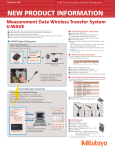
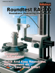
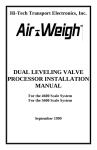
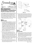
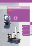
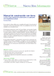
Form Measurement Compact Roundness Measurement ROUNDTEST RA-220 Bulletin No. 1977 Compact roundness tester equipped with a wide range of analysis features and capable of flexibly accommodating a variety of workpieces Powerful Analysis Performance in a Compact Body Roundtest RA-220 Compact manual machine for measuring roundness and cylindrical form including cylindricity measurement s¬-ULTIPLE¬ANALYSES¬THROUGH¬SIMPLE¬OPERATION s¬&INE¬ADJUSTMENT¬ON¬BOTH¬8¬AND¬:AXES s¬3CALED¬:AXIS s¬#ONTINUOUS¬)$¬AND¬/$¬MEASUREMENT s¬$!4¬FUNCTION s¬7IDERANGE¬DETECTOR s¬(IGH¬ACCURACY¬OFFERED¬IN¬A¬COMPACT¬BODY¬ (features high-accuracy air bearing) * See page 4 for details. Various types of Analysis Radial 4HICKNESS¬VARIATION Axial Radial #IRCULAR¬RUNOUT Axial Cylindricity Flatness 3QUARENESS Relative to Plane Relative to Axis /F¬SECTION Concentricity ■ 3AMPLE¬PRINTS /F¬AXIS Coaxiality Print measurement conditions, computation results, result graphs, comments, etc., to the thermal printer. Change development graphs and output items as desired. 4YPE¬OF¬ Measurement Evaluation Analysis mode diagram Parallelism Roundness 4YPE¬OF¬ Measurement Evaluation Analysis mode diagram (IGHGRADE¬THERMAL¬PRINTER File save Call up by one touch of a button Save and access [Measurement files] and [Result files] in USB memory. Data can also be totaled using the data output function with commercial tabulation software. Four measurement files can be independently assigned to buttons. /NETOUCH¬RECALL ⇒ 3IMPLE¬OPERATION ⇒ Prevention of operational errors 2 %ASYTOUNDERSTAND¬OPERATION¬PANEL¬WITH¬LARGE¬,#$ /PERATING¬PANEL¬THAT¬IS¬READ¬AT¬A¬GLANCE /PERATING¬PANEL "LACK¬AND¬WHITE¬,#$¬SCREEN Operating panel that is read at a glance Easy-to-read screen displays essential information Analysis type Selection buttons provide access to a wide variety of analysis types 3IMPLE¬SETUP Apply the current measurement setup in one go Simple operation helps prevent operational errors 3WITCHING¬SCREEN¬MODES Switch the display at the touch of a button, providing access to the Calibration, Centering and Leveling, Measurement and Result screens Jog dial Make incremental changes to setup and other operations :EROSETTING¬BUTTON No fine adjustment necessary for setting the measurement position 3IMPLE¬INTERACTIVE¬DISPLAY¬SCREEN The large LCD screen with backlight shows easy-to-understand measurement results and graphs. Forms can be checked and notch processing can be set while observing the displayed graphs. Measurement screen Measurement results s¬3ET¬THE¬POSITION¬OF¬THE¬DETECTOR¬AND¬MEASUREMENT¬CONDITIONS¬HERE s¬$URING¬MEASUREMENT¬GRAPHS¬ARE¬DISPLAYED¬IN¬REAL¬TIME s¬&ILTER¬DISPLAY¬MAGNIlCATION¬ETC¬CAN¬BE¬ALTERED s¬"ESIDES¬CIRCLES¬DEVELOPED¬VIEWS¬CAN¬ALSO¬BE¬DISPLAYED ▲ Measurement screen ▲ Measurement Result screen ▲ in progress screen 3 (IGHLEVEL¬FUNCTIONS¬PROMOTE¬GREATER¬EFlCIENCY $!4¬FUNCTION¬ Patent registered (in Japan) This instrument uses the D.A.T (Digital Adjustment Table) function available on more sophisticated models, and this provides powerful support for centering and leveling operations. To perform such operations, the user need only adjust the digital micrometer heads attached to the rotary table by the amounts indicated by the display. This function also supports notched workpieces. Mode selection Preliminary setup Centering ,EVELING %#+!+ #!%%! %+ %! +#!+%+)$ %#+!+#!%%! % !#" !#" !%#* + !%#*+ % %+!$%+#!+ %#+!+#!%%! &$%+%+%+#!%#+$+ ! +%+#!%#*+%+*+ %+!& %+ %+%!+!##%+ %+ %+!$%+ + %! $%+# +&$% %+, %! +# +&$% %+,- # #*+ $&# % $"*$+!& %+ !+!$% %! "+ &$% % %# ' + !"% (!+"# #*+$&# %$+#+ +%+#!$$$%! $++ + )./54¬SWITCHABLE¬WIDERANGE¬DETECTOR The range of this detector has been extended from that of a conventional lever head by as much as four times, and now provides a wide 2000μm stroke. The detector can provide sufficient margin for centering and leveling jobs, or when measuring large differences. Moreover, the measuring direction can be switched between inside and outside diameters with a single touch of a button. 2000μm 3TANDARD¬ACCESSORIES¬THAT¬ENHANCE¬ MEASUREMENT¬EFlCIENCY :AXIS¬SCALE This scale is useful when the measuring height position needs to be entered, such as when measuring coaxiality, etc. #ONTINUOUS¬)$¬AND¬/$¬MEASURING¬FUNCTION Patent registered (in Japan, USA, Germany, UK, France) This function comes in very handy when outside and inside surfaces need to be measured repeatedly, for example, with respect to coaxiality, deviation in wall thickness, etc. 8AXIS¬STOP Allows the user to return the detector rapidly and easily to a fixed position in the X axis. IN/OUT Switchable wide-range detector Making an inside-surface- Making an outside-surfacerelated measurement related measurement 4 3PECIlCATIONS ■ Main unit Model /RDER¬.O Rotational accuracy: Radial Rotational accuracy: Axial Rotation speed Effective table diameter Maximum loading weight Turntable unit Maximum probing diameter *1 Vertical drive unit (Z-axis) Radial drive unit (X-axis) Detector *2 Maximum workpiece diameter Parallelism to rotation center Straightness Vertical travel Maximum probing height *1 Maximum probing depth Horizontal travel Measuring force Standard stylus tip Measuring range Measuring direction Measuring range Recording magnification Filter type Cutoff value Number of measuring cross sections Electronic unit Reference circle for roundness evaluation Data analysis items Data output Printer Power supply Power consumption Specified air pressure Air consumption Mass Others 2! ! H: Measuring height (mm) JIS B7451-1997 X: Distance from the rotation center (mm) (0.04+6H/10000)μm (0.04+6X/10000)μm 6 rpm ø 6" (ø 150mm) 55lbs (25kg) ø 11"(280mm ) (ø 14.96"(380mm): when detector holder is installed in reverse; in the vertical posture only; maximum measuring height is up to 2" (50 mm) from the table top) ø 18.5" (ø 470mm) 0.5 μm/100mm Narrow range: 0.2μm/20mm Wide range: 0.5 μm/100mm 11.02" (280mm) from the turntable top 11.02" (280mm) from the turntable top 4" (100mm) (minimum ID: 30mm) -1"~ 5.5" (−25mm ~ 140mm) 70 ~ 100mN (±30%) Carbide ball, ø 1.6mm ±1000μm IN/OUT switchable ±1000, ±100, ±10 μm (3 steps) ×5, ×10, ×20, ×50, ×100, ×200, ×500, ×1K, ×2K, ×5K, ×10K, ×20K, ×50K, ×100K, ×200K (15 steps) With phase-correction: 2CRPC75, 2CRPC50 Without phase-correction: 2CR75, 2CR50 Gaussian, Filter OFF Low pass: 15 upr, 50 upr, 150 upr, 500 upr Band pass: 15-150 upr, 15-500 upr, 50-500 upr ① 1 to 5 cross sections : Roundness, Coaxiality, Flatness ② 1 to 3 cross sections : Radial runout, Squareness (axis reference) ③ 2 cross sections: Concentricity, Thickness deviation, Parallelism ④ 3 cross sections: Squareness (plane reference) ⑤ 3 to 5 cross sections : Cylindricity Least square circle method (LSC), Minimum zone circle method (MZC), Maximum inscribed circle method (MIC), Maximum circumscribed circle method (MCC) Roundness, Coaxiality, Concentricity, Flatness, Circular run-out (radial), Circular run-out (axial), Squareness (relative to axis), Squareness (relative to plane), Thickness deviation, Parallelism, Cylindricity USB, RS-232C, SPC Thermal line printer, External printer (option) AC100 ~ 240V 33W 0.39MPa 30 L /min or over (Standard state) Main unit: 332 lbs (151kg) Air filter: 4.4 lbs (2kg) *1: Use an auxiliary workpiece stand (option) when measuring a workpiece whose diameter is .78" (20mm) or less and whose height is .78" (20mm) or less from the top surface of the alignment table. *2: The detector supports standard-length styli only. Long styli cannot be used. ■ 3TANDARD¬ACCESSORIES Order No. ■ Reference hemisphere Name of Parts QTY Reference hemisphere 1 Calibration film 2 !!" Standard stylus 1 Battery 5 ------ Remarks SR44: For Micrometerheads (D.A.T function), For ABS-SD scale (Z axis) Printer paper ( 2), X-axis stop (1), Coupler(socket) (1), Hose band (1), Power cord (1), Philips screwdriver (1), Allen wrench(Nominal size:0.9mm) (1), Allen wrench(Nominal size:2mm) ( 2), Allen wrench(Nominal size:2.5mm) (1), Vinyl cover (1), Hanger bolt (4 ), User's manual (1) *Number in ( ) shows quantity 5 Order No. /PTIONAL¬!CCESSORIES ■ )NTERCHANGEABLE¬3TYLI *Standard accessory (stylus tip: ø1.6 carbide ball) !!" Standard stylus Unit: mm !!" Stylus for notched workpieces (stylus tip: ø3 carbide ball) !!" Stylus for grooves (stylus tip: R0.25 sapphire) !!" Stylus for corners (stylus tip: R0.25 sapphire) &OR¬INSIDECORNER¬APPLICATIONS &OR¬STEPPED¬APPLICATIONS 5SEFUL¬FOR¬NOTCHED¬WORKPIECES &OR¬STANDARD¬APPLICATIONS %XAMPLE &OR¬EXTRA¬SMALL¬HOLE¬APPLICATIONS $IA¬rMM¬$EPTH¬bMM %XAMPLE ª !!% Stylus for small and deep holes (stylus tip: ø1.6 carbide ball) !!" Stylus for small and deep holes (stylus tip: ø1.6 carbide ball) !!% Stylus for small holes (stylus tip: ø0.8 carbide ball) !!" Stylus for extra small holes (stylus tip: ø0.5 carbide ball) %XAMPLE )N¬)$¬MEASUREMENT $IA¬rMM¬$EPTH¬bMM &OR¬SMALL¬AND¬DEEP¬HOLE¬APPLICATION $IA¬rMM¬$EPTH¬bMM &OR¬SMALL¬AND¬DEEP¬HOLE¬APPLICATIONS $IA¬rMM¬$EPTH¬bMM &OR¬SMALL¬HOLE¬APPLICATIONS $IA¬rMM¬$EPTH¬bMM %NLARGED¬IMAGE %NLARGED¬IMAGE %NLARGED¬IMAGE ¬CARBIDE¬BALL ¬CARBIDE¬BALL ¬CARBIDE¬BAL &OR¬UPPERLOWER¬SURFACE¬IN¬A¬NARROW¬GROOVE %XAMPLE !!% Stylus for flat surface 2 %XAMPLE ¬CARBIDE¬BALL !!" Cranked stylus (stylus tip: ø1 carbide ball) ¬CARBIDE¬BALL !!" !!" Stylus for small holes (stylus tip: ø1 carbide ball) Cranked stylus (stylus tip: ø0.5 carbide ball) &OR¬SMALL¬HOLE¬APPLICATIONS ¬CARBIDE¬BALL %NLARGED¬IMAGE .OTE¬4HIS¬STYLUS¬CANNOT¬BE¬ USED¬FOR¬/$)$¬MEASUREMENT ¬CARBIDE¬BALL !!" Disk stylus !!" M2 tapped shank for CMM styli %XAMPLE &OR¬NARROW¬GROOVE¬ APPLICATIONS %XAMPLE #OMPATIBLE¬WITH¬#--¬STYLI¬ WITH¬-¬THREADED¬SHANK #OMPATIBLE¬WITH¬#--¬STYLI¬ WITH¬-¬THREADED¬SHANK &ILTERING¬OUT¬THE¬EFFECTS¬OF¬ ASPERITIES¬BY¬TRACING¬WITH¬2¬ TIPPED¬STYLUS ª 2 !!% M2 tapped shank for CMM styli !!" Stylus for filtering asperities (machining marks) #UTTER¬MARK 2 -¬DEPTH¬ - *■ portion shows stylus except for the cranked stylus and stylus for flat surface. *( ) dimension shows a distance from the tip end of stylus or the center of tip ball to the connecting surface of detector. *Customized special interchangeable styli are available on request. Please contact any Mitutoyo office for more information. 6 ■ Centering chuck (knurled ring operated) Provides good operability when measuring a small-diameter workpiece. The knurled ring allows the workpiece to be clamped easily. /RDER¬.O Holding range OD with internal jaws 11–36 mm ID with internal jaws 16–69 mm OD with internal jaws 25–79 mm External size ø 4.65”x 1.6” (118 x 41 mm) (D x H) Mass 2.6 lbs (1.2 kg) ■ Collet chuck Provides high clamping repeatability due to the use of optional precision collets. (See table at right.) /RDER¬.O Part holding range Centering error Mass ø0.5–10 mm*2 Within 50 μm*3 3 lbs (1.4 kg) *2: Collets to match the workpiece size range are required for use with this chuck. *3: When measured with ø5 mm pin gauge at measuring height of 30 mm. ■ 6IBRATIONDAMPING¬STAND BENCHTOP¬TYPE ■ 4HREEJAW¬CHUCK¬KEY¬OPERATED ■ Microchuck Useful where it is necessary to apply a higher clamping force to the workpiece than can be applied with the centering chuck. For clamping a small workpiece, 1 mm or less in diameter, that cannot be held in the centering chuck. /RDER¬.O Holding range OD with internal jaws 12–26 mm ID with internal jaws 25–68 mm OD with internal jaws 35–78 mm External size ø 6.18” x 2.78” (157 x 70.6 mm) (D x H) Mass 8.4 lbs (3.8 kg) ■ )NDIVIDUAL¬COLLETS These collets are for use with the collet chuck shown at left and are acquired to match the workpiece diameter range required. /RDER¬.O !!( !!( !!( !!( !!( !!( !!( !!( !!( !!( !!( !!( !!( Part Holding Range (O.D.) ø0.02”– 0.04” (0.5–1.0mm) ø0.04”– 0.06” (1.0–1.5mm) ø0.06”– 0.08” (1.5–2.0mm) ø0.08”– 0.1” (2.0–2.5mm) ø0.1”– 0.12” (2.5–3.0mm) ø0.12”– 0.138” (3.0–3.5mm) ø0.138”– 0.157” (3.5–4.0mm) ø0.157”– 0.197” (4.0–5.0mm) ø0.197”– 0.236” (5.0–6.0mm) ø0.236”– 0.275” (6.0–7.0mm) ø0.275”– 0.315” (7.0–8.0mm) ø0.315”– 0.354” (8.0–9.0mm) ø0.354”– 0.394” (9.0–10.0mm) *4: A collet cannot be mounted on the rotary table without a collet chuck. *4: YCC10-** Class AA, made by Yukiwa Seiko Inc. or its equivalent. /RDER¬.O Vibration damping system Preumatic type w/ self-leveling External size 25” x 20” x 2” 610 x 508 x 51mm Max. loading mass 175 lbs (80 kg) /RDER¬.O Holding range External size (D x H) Mass OD: up to 1.5 mm ø4.65” x 1.9” (118 x 48.5 mm) 1.32 lbs (0.6 kg) ■ Auxiliary stage for a short workpiece Order No. ■ -AGNIlCATION¬CHECKING¬GAGE Order No. ■ Gage block set for calibration Order No. ■ Cylindrical square /RDER¬.O Straightness Cylindricity External size (DxH) Mass 7 0.5μm 2μm ø70 x 250mm 7.5kg Dimensions ■ External dimensions 50 200 226 52 775 781(MAX) 525 Unit: mm φ70 238.5 500 750 (MAX) 184.5 423 547 One Number to Serve You Better 1-888-MITUTOYO (1-888-648-8869) Aurora, Illinois (Corporate Headquarters) Note: All information regarding our products, and in particular the illustrations, drawings, dimensional and performance data contained in this printed matter as well as other technical data are to be regarded as approximate average values. We therefore reserve the right to make changes to the corresponding designs. The stated standards, similar technical regulations, descriptions and illustrations of the products were valid at the time of printing. In addition, the latest applicable version of our General Trading Conditions will apply. Only quotations submitted by ourselves may be regarded as definitive. Mitutoyo products are subject to US Export Administration Regulations (EAR). Re-export or relocation of Mitutoyo products may require prior approval by an appropriate governing authority. Trademarks and Registrations Designations used by companies to distinguish their products are often claimed as trademarks. In all instances where Mitutoyo America Corporation is aware of a claim, the product names appear in initial capital or all capital letters. The appropriate companies should be contacted for more complete trademark and registration information. We reserve the right to change specifications and prices without notice. ^ÊÓä£äÊÌÕÌÞÊiÀV>Ê À«À>Ì]ÊÕÀÀ>ÊÊÊÊÊÊÊÊÊÊÊÊÊÊÊÊÊÊÊÊÊÊÊÊÊÊÊÊÊÊÊÊÊäääÇÊUÊ*ÀÌi`ÊÊ1-ÊUÊ>ÀV ÊÓä£ä Westford, Massachusetts Huntersville, North Carolina Mason, Ohio Plymouth, Michigan City of Industry, California