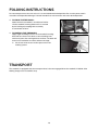
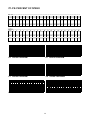
1
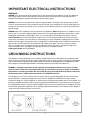
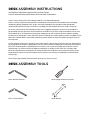
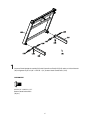
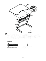
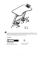
Walkdesk WTD200 owner’s Manual PLEASE CAREFULLY READ THIS ENTIRE MANUAL BEFORE OPERATING YOUR NEW ELLIPTICAL Stadsheide 3 | 3500 Hasselt1| Belgium | T +32 11 76 12 70 [email protected] | www.bodysolid-europe.com TABLE OF CONTENTS Important Safety Instructions 2 Important Electrical Instructions 3 Grounding Instructions 3 Important Operation Instructions 4 Desk Assembly Instructions 5 Folding/Transport Instructions 10 Console Operation 11 General Maintenance 15 Service Checklist – Diagnosis guide 18 Exploded View Diagram/Parts List 19 ATTENTION This treadmill is intended for residential use only and is warranted for this application. Any other application voids this warranty in its entirety. 1 IMPORTANT SAFETY INSTRUCTIONS WARNING - Read all instructions before using this appliance. DANGER - To reduce the risk of electric shock disconnect your treadmill from the electrical outlet prior to cleaning and/or service work. WARNING - To reduce the risk of burns, fire, electric shock, or injury to persons, install the treadmill on a flat level surface with access to a 230~volt, 10-amp grounded outlet with only the treadmill plugged into the circuit. DO NOT USE AN EXTENSION CORD UNLESS IT IS A 14AWG OR BETTER, WITH ONLY ONE OUTLET ON THE END. The treadmill should be the only appliance in the circuit in which it is connected. DO NOT ATTEMPT TO DISABLE THE GROUNDED PLUG BY USING IMPROPER ADAPTERS, OR IN ANY WAY MODIFY THE CORD SET. A serious shock or fire hazard may result along with computer malfunctions. See Grounding Instructions. Do not operate treadmill on deeply padded, plush or shag carpet. Damage to both carpet and treadmill may result. Do not block the rear of the treadmill. Provide a minimum of 3 1/2 feet clearance between the rear of the treadmill and any fixed object. Keep children away from the treadmill. There are obvious pinch points and other caution areas that can cause harm. Keep hands away from all moving parts. Never operate the treadmill if it has a damaged cord or plug. If the treadmill is not working properly, call your dealer. Keep the cord away from heated surfaces. Do not operate where aerosol spray products are being used or where oxygen is being administered. Sparks from the motor may ignite a highly gaseous environment. Never drop or insert any object into any openings. Do not use outdoors. To disconnect, turn all controls to the off position, then remove the plug from the outlet. Do not attempt to use your treadmill for any purpose other than for the purpose it is intended. The hand pulse sensors are not medical devices. Their purpose is to provide you with an approximate measurement in relation to your target heart rate. Use of a chest transmitter strap is a much more accurate method of heart rate analysis. Various factors, including the user’s movement, may affect the accuracy of heart rate readings. The pulse sensors are intended only as exercise aids in determining heart rate trends in general. Use handrails provided; they are for your safety. Wear proper shoes. High heels, dress shoes, sandals or bare feet are not suitable for use on your treadmill. Quality athletic shoes are recommended to avoid leg fatigue. SAVE THESE INSTRUCTIONS - THINK SAFETY 2 IMPORTANT ELECTRICAL INSTRUCTIONS WARNING! NEVER use a ground fault circuit interrupt (GFCI) wall outlet with this treadmill. As with any appliance with a large motor, the GFCI will trip often. Route the power cord away from any moving part of the treadmill including the elevation mechanism and transport wheels. NEVER remove any cover without first disconnecting AC power. If voltage varies by ten percent (10%) or more, the performance of your treadmill may be affected. Such conditions are not covered under your warranty. If you suspect the voltage is low, contact your local power company or a licensed electrician for proper testing. NEVER expose this treadmill to rain or moisture. This product is NOT designed for use outdoors, near a pool or spa, or in any other high humidity environment. The operating temperature specification is 40 to 120 degrees Fahrenheit, and humidity is 95% non-condensing (no water drops forming on surfaces). Circuit Breakers: Some circuit breakers used in homes are not rated for high inrush currents that can occur when a treadmill is first turned on or even during use. If your treadmill is tripping the house circuit breaker (even though it is the proper current rating) but the circuit breaker on the treadmill itself does not trip, you will need to replace the home breaker with a high inrush type. This is not a warranty defect. This is a condition we as a manufacture have no ability to control. This part is available through most electrical supply stores. Examples: Grainger part # 1D237, or available online at www.squared.com part # QO120HM. GROUNDING INSTRUCTIONS This product must be grounded. If the treadmill should malfunction or breakdown, grounding provides a path of least resistance for electric current, reducing the risk of electric shock. This product is equipped with a cord having an equipment-grounding plug. The plug must be plugged into an appropriate outlet that is properly installed and grounded in accordance with all local codes and ordinances. DANGER - Improper connection of the equipment-grounding conductor can result in a risk of electric shock. Check with a qualified electrician or serviceman if you are in doubt as to whether the product is properly grounded. Do not modify the plug provided with the product if it will not fit the outlet; have a proper outlet installed by a qualified electrician. This product is for use on a nominal 230~volt circuit, and has a grounding plug that looks like the plug illustrated below. A temporary adapter that looks like the adapter illustrated below may be used to connect this plug to a 2-pole receptacle as shown below if a properly grounded outlet is not available. The temporary adapter should be used only until a properly grounded outlet, (shown below) can be installed by a qualified electrician. The green colored rigid ear-lug, or the like, extending from the adapter, must be connected to a permanent ground such as a properly grounded outlet box cover. Whenever the adapter is used, it must be held in place by a metal screw. 3 IMPORTANT OPERATION INSTRUCTIONS NEVER operate this treadmill without reading and completely understanding the results of any operational change you request from the computer. Understand that changes in speed and incline do not occur immediately. Set your desired work level on the computer console and release the adjustment key. The computer will obey the command gradually. NEVER use your treadmill during an electrical storm. Surges may occur in your household power supply that could damage treadmill components. Unplug the treadmill during an electrical storm as a precaution. Use caution while participating in other activities while walking on your treadmill; such as watching television, reading, etc. These distractions may cause you to lose balance which may result in serious injury. Do not use excessive pressure on console control keys. They are precision set to function properly with little finger pressure. SAFETY TETHER CORD A safety tether cord is provided with this unit. It is a simple magnetic design that should be used at all times. It is for your safety should you fall or move too far back on the tread-belt. Pulling this safety tether cord will stop tread-belt movement. To Use: 1. Place the magnet into position on the round metal portion of the console control head. Your treadmill will not start and operate without this. Removing the magnet also secures the treadmill from unauthorized use. 2. Fasten the plastic clip onto your clothing securely to assure good holding power. Note: The magnet has strong enough power to minimize accidental, unexpected stopping. The clip should be attached securely to make certain it does not come off. Be familiar with its function and limitations. The treadmill will stop, depending on speed, with a one to two step coast anytime the magnet is pulled off the console. Use the Stop / Pause switch in normal operation. 4 DESK ASSEMBLY INSTRUCTIONS !!ATTENTION: IMPORTANT UNPACKING INSTRUCTIONS. PLEASE READ BEFORE UNPACKING YOUR FOLDING TREADMILL!! Serious injury could occur if this folding treadmill is not unpacked properly. There is a Velcro strap installed around the treadmill base that prevents the treadmill from unfolding accidentally during shipping. If this strap is not removed properly the treadmill could spring open unexpectedly and cause injury if someone is standing near the treadmill when the strap is removed. To ensure your personal safety during removal of the shipping strap please make sure the treadmill is positioned flat on the ground, in the orientation it would be in if you were using the treadmill. Do not turn the treadmill up on its side while removing the shipping strap. This could cause the treadmill’s folding mechanism to spring open. If the end of the Velcro strap (that you need to grab to remove it) happens to be under the treadmill deck, reach under the deck to grab it, but do not tilt the treadmill up to gain access to the strap end. Cut the banding straps with a short box cutter (razor knife); separate the carton from the one underneath it by prying up on the staples (if applicable). Pull the carton over the treadmill parts and locate the hardware pack. The hardware pack is separated into five sections; one section containing tools and four sections labeled steps 1-4 which contain the hardware needed for assembly of each step. The assembly steps below are numbered one through four and correspond to the hardware in the numbered sections of the hardware pack. Remove only the hardware for the step you are currently assembling to avoid confusion and mix ups. Then remove the treadmill from the carton and lay it on a level surface. DESK ASSEMBLY TOOLS #142. M5 Allen Wrench #139. Phillips Head Screw Driver #141. L Allen Wrench #140. Wrench 5 1 Connect Fixed Upright Assembly(113) with Frame Base Tube(L.R)(116) and use L Allen Wrench (141) to tighten 16 pcs of 3/8” × UNC16 × 1/2”_Button Head Socket Bolts (135). HARDWARE #135. 3/8” × UNC16 × 1/2” Button Head Socket Bolt (16 pcs) 6 2 Lay Deck Board (120) on Sliding Upright Assembly (114) with two Nuts(121) to secure with Desk Board Stand (115). Secure Desk Board Stand (115) on Sliding Upright Assembly(114) by using open end wrench (140) and Allen wrench (141) to tighten 2pcs of 3/8” × UNC16 × 1-3/4”_Button Head Socket Bolts (136) and 2pcs of 3/8” × UNC16 × 7T_Nyloc Nuts(137). HARDWARE #136. 3/8” × UNC16 × 1-3/4” Button Head Socket Bolt (2 pcs) #137. 3/8” × UNC16 × 7T Nyloc Nut (2 pcs) 7 3 1.Slide Computer Cable(Upper)(46) (DT520-YT55) Use Phillips Head Screw Driver (139) to tighten 4 pcs of M5 × P0.8 × 12L_Phillips Head Screw (112) to secure Console assembly(66) DT520-YT55) on Console Bracket Assembly(106). 2.Locate Console Bracket Assembly(106) in the Right Desk Board(120), to secure Console Bracket Assembly(106) on Brake Tension Knob(107) HARDWARE #112. M5 × P0.8 × 12L Phillips Head Screw (4 pcs) 8 4 Use Allen wrench (142) and open end wrench (140) to tighten four 5/16”×UNC18×2” Button Head Socket Bolts(70), together with four 5/16”×UNC18×7T(mm) Nyloc Nuts (79) for two Limit Bracket(R.L) (118.119) through both Frame Base Tubes (116). HARDWARE #70. 5/16”×UNC18×2” Button Head Socket Bolt (4 pcs) #79. 5/16” ×UNC18× 7T Nyloc Nut (4 pcs) 9 FOLDING INSTRUCTIONS Do not attempt to move the unit unless it is in the folded and locked position. Be sure the power cord is secured to avoid possible damage. Use both handrails to maneuver the unit to the desired position. TO FOLD THE TREADMILL Make certain the treadmill is at minimum incline. Lift the treadmill running deck until it is secured by the locking telescoping tube assembly in center back of base. TO UNFOLD THE TREADMILL Apply slight forward pressure* on the treadmill running deck with one hand. Pull down on the unlocking lever and slowly lower the running deck to the floor. The deck will lower unassisted when it reaches about waist high. *At the rear roller area to relieve pressure on the Locking system. TRANSPORT The treadmill is equipped with four transport wheels that are engaged when the treadmill is folded. After folding simply roll the treadmill away. 10 OPERATION OF YOUR CONSOLE GETTING FAMILIAR WITH THE CONTROL PANEL FUNCTION BUTTON FUNCTION BUTTON INITIAL DISPLAY When the power is turned on, main window will bright and show all parameter, then show the current software version, how many hours the treadmill has been in use and how many Kilometers (or Miles if the treadmill is set to imperial readings), above each data will be shown for 2 seconds in order, the treadmill has gone. The treadmill will enter idle mode and show the P0 (Manual program), which is the starting point for operation. WINDOW DISPLAY SCAN:Each parameter will take turns to display the exercising data for 5 seconds. SPEED: Displays the current running speed from 0.8 KPH ~ 6.0 KPH. TIME:Accumulates total workout time from 00:00 to 99:59. DISTANCE:Accumulates total workout distance from 0.00 to 99.99 Kilometers (99.99Miles). CALORIES:Accumulates the user’s calories consumption during exercise. Max. Value is 999.9 calories. Note: This is only a rough guide used for comparison of different exercise sessions, which cannot be used for medical purposes. PROGRAM: To choice training program that have P0 (MANUAL) and P1~P5 (PRESET PROGRAMS). 11 Function Button ENTER: Press “ENTER” button to set the parameter of count down. When the belt stop running which press and hold this button for 3 seconds to reset all data which is the parameter value of accumulating. START/STOP: Press “ST/SP” button to control start or stop training. SPEED+: Press “FAST’ button to increase your speed, each increment is 0.1KPH. SPEED-: Press “SLOW” button to decrease your speed, each decrement is 0.1KPH. PROGRAM : Program selection button, P0 is the manual mode, P1~P5 are with various speed of programs. SAFETY KEY: Attach the safety key in its position to power on the computer. When safety key is pulled away from its position, the computer will shut down automatically. DIRECT SPEED KEYS: 3 preset buttons for direct speed: 1kph/1mph, 3kph/2mph, 5kph/3mph. user can press the 3buttons, mentioned above, at any time, to start treadmill and treadmill will automatically adjust to press speed. Quick-Start Operation (P0-Manual): STEP 1: Attach the Safety button to wake display up (if not already on), the main window will show initial displaying. (Before training, you could enter the setting of count down, please see the STEP 6.) STEP 2: Press the START/STOP button to begin belt movement, before training; the console will be a 3 seconds final count down and a beep sound for short time. Using the SPEED +/- keys to adjust the desired speed (on console) at any time during training. STEP 3: Press ENTER button to see the value of parameter, which includes speed, time, distance, calories or scan. If chooses the scan mode that will take turns to display all value of parameter every 5 seconds. STEP 4: While training, you can press ST/SP button to stop your workout or pull safety key away from its position to shut down the computer. If you want to resume your workout, you can press ST/SP button again and all previous data will resume counting. STEP 5: After training, to press ENTER button to display the accumulating data for speed, time, distance and calories that will be memorize during training. If you want to repeat your workout, press START/STOP button to start the treadmill again then others parameter will resume counting. STEP 6: Before training, press ENTER button to enter the setting of count down which include setting count down Time whose range is from 10: 00 to 99:00, Distance is from 0.1 to 99.9 or Calories is from 1.0 to 999. During setting, you could press SPEED+/- to adjust the value or press ENTER button to enter next step whether you set or not. When you set multi-parameter, just single parameter can to count down in last setting, press START/STOP to execute the setting. When parameter has gone to zero, the treadmill will stop immediately, this workout summary will be showed on screen. 12 To Select a Program: P1 ~ P5 (PRESET PROGRAM) Step 1. Press “ P (program) ” button to choose P0 (manual), P1 ~ P5, each program has a preset speed value. Step 2. Press ENTER button to set the count down time from 10:00 to 99:00, preset value is 20:00. You can adjust the value by pressing SPEED + / - or press START/STOP button to start training immediately. For example: Time is limited to 20 minutes wherein total segments are 20 and each segment exercising time is 1 minute. When Time goes to zero, treadmill will stop which could press START/STOP to repeat and time will count down again, others will to accumulate resuming. Step 3. Press START/STOP button to stop your workout or pull safety key away from its position to shut down the computer. Step 4. When workout is finished, press and hold ENTER button for 3 seconds to reset and initial software in Manual(P0) program. LUBE: When accumulated workout time duration is over 90 hours after lubrication, the LUBE warning shows up. To follow this message lubricates deck. ERROR MESSAGE: 1. LS: Treadmill doesn’t receive the speed signal for 8 seconds. 2. E1: Memory of console malfunction or CPU accessing proble 13 P1-P5: PERCENT OF SPEED KPH------------------------------------------------------------------------------------------------------Prog 1 2 3 4 5 6 7 8 9 10 11 12 13 14 15 16 17 18 19 20 P_1 1.0 1.5 2.0 2.5 2.5 3.0 3.0 4.0 4.0 3.5 3.5 4.0 4.0 3.0 3.0 2.5 2.5 2.0 1.5 1.0 P_2 1.0 2.0 3.0 4.0 4.0 4.0 4.0 4.0 4.0 4.0 4.0 4.0 4.0 4.0 4.0 4.0 4.0 3.0 2.0 1.0 P_3 1.5 2.0 3.0 3.0 3.5 4.0 3.0 3.5 4.0 4.5 3.0 3.5 4.0 3.0 4.0 4.0 4.5 3.5 3.0 2.0 P_4 1.5 2.0 2.0 2.5 2.5 3.0 3.0 3.5 3.5 4.0 4.0 4.0 4.5 4.5 5.0 5.0 5.0 3.5 2.5 1.5 P_5 2.0 4.0 4.0 2.0 2.0 4.0 4.0 2.0 2.0 4.0 4.0 2.0 2.0 4.0 4.0 2.0 2.0 4.0 4.0 2.0 MPH------------------------------------------------------------------------------------------------------Prog 1 2 3 4 5 6 7 8 9 10 11 12 13 14 15 16 17 18 19 20 P_1 0.5 1.0 1.5 1.5 1.5 2.0 2.0 2.5 2.5 2.0 2.0 2.5 2.5 2.0 2.0 1.5 1.5 1.5 1.0 0.5 P_2 0.5 1.0 2.0 2.5 2.5 2.5 2.5 2.5 2.5 2.5 2.5 2.5 2.5 2.5 2.5 2.5 2.5 2.0 1.0 0.5 P_3 0.5 0.5 1.0 1.0 1.5 2.0 1.0 1.5 2.0 2.5 1.0 1.5 2.0 1.0 2.0 2.0 2.5 1.5 1.0 0.5 P_4 1.0 1.0 1.0 1.5 1.5 1.5 1.5 1.5 2.0 2.0 2.0 2.0 2.0 2.5 2.5 2.5 2.5 2.5 1.5 1.0 P_5 1.0 2.5 2.5 1.0 1.0 2.5 2.5 1.0 1.0 2.5 2.5 1.0 1.0 2.5 2.5 1.0 1.0 2.5 2.5 1.0 P0 SPEED PROGRAM P3 SPEED PROGRAM P1 SPEED PROGRAM P4 SPEED PROGRAM P2 SPEED PROGRAM P5 SPEED PROGRAM 14 14 GENERAL MAINTENANCE BELT/DECK Your treadmill uses a very high-efficient low-friction deck. Performance is maximized when the deck is kept as clean as possible. Use a soft, damp cloth, or paper towel, wipe the edge of the belt and the area between the belt edge and the frame. Also reach as far as practical directly under the belt edge. This should be done once a month to extend belt and deck life. A mild soap and water solution along with a nylon scrub brush will clean the top of the textured belt. Allow to dry before using. BELT/DECK This occurs during normal break-in or until the belt stabilizes. Sometimes the black dust from the belt will appear on the floor behind the treadmill, this is normal. GENERAL CLEANING Dirt, dust, and pet hair can block air inlets and accumulate on the running belt. Please vacuum underneath your treadmill on a monthly basis to prevent excess build-up of dirt that can get sucked up and get into the inner workings under the motor cover. Once a year, you should remove the black motor hood and vacuum out dirt that may accumulate. UNPLUG POWER CORD BEFORE THIS TASK. BELT ADJUSTMENTS Tread-belt Tension Adjustment - Belt tension is not critical for most users. It is very important though for joggers and runners in order to provide a smooth, steady running surface. Adjustment must be made from the rear roller with the 6 mm Allen wrench provided in the parts package. The adjustment bolts are located at the end of the step rails as shown in the diagram below. Tighten the rear roller only enough to prevent slippage at the front roller. Turn the tread-belt tension adjusting bolts 1/4 turn each and inspect for proper tension by walking on the belt and making sure it is not slipping or hesitating with each step. When an adjustment is made to the belt tension, you must be sure to turn the bolts on both sides evenly or the belt could start tracking to one side instead of running in the middle of the deck. DO NOT OVERTIGHTEN – Over tightening will cause belt damage and premature bearing failure. If you tighten the belt a lot and it still slips, the problem could actually be the drive belt - located under the motor cover - that connects the motor to the front roller. If that belt is loose it feels similar to the walking belt being loose. Tightening the motor belt should be done by a trained service person. 15 TREADBELT TRACKING ADJUSTMENT The treadmill is designed so that the tread-belt remains reasonably centered while in use. It is normal for some belts to drift near one side while in use, depending on a user’s gait and if they favor one leg. But if during use the belt continues to move toward one side, adjustments are necessary. SETTING TREAD-BELT TRACKING A 6 mm Allen wrench is provided for this adjustment. Make tracking adjustments on the left side bolt. Set belt speed at 3 mph ( 5 kmph). Be aware that a small adjustment can make a dramatic difference which may not be apparent right away. If the belt is too close to the left side, then turn the bolt only a 1/4 turn to the right (clockwise) and wait a few minutes for the belt to adjust itself. Continue to make 1/4 turns until the belt stabilizes in the center of the running deck. If the belt is too close to the right side, turn the bolt counter-clockwise. The belt may require periodic tracking adjustment depending on use and walking/running characteristics. Some users may affect tracking differently. Expect to make adjustments as required to center the tread-belt. Adjustments will become less of a maintenance concern as the belt is used. Proper belt tracking is an owner responsibility common with all treadmills. ATTENTION: DAMAGE TO THE RUNNING BELT RESULTING FROM IMPROPER TRACKING / TENSION ADJUSTMENTS IS NOT COVERED UNDER THE WARRANTY. 16 BELT/DECK LUBRICATION PROCEDURE BELT/DECK LUBRICATION PROCEDURE Do not with other approved lubricant.lubricant. Your treadmill Dolubricate not lubricate withthan other than approved Your comes with onecomes tube ofwith lubricant and extra tubes can beextra ordered treadmill one tube of lubricant and tubes can directly yourdirectly authorized dealer. There are commercially available befrom ordered from your authorized dealer. There are lube kits, but the only one currently approved is Lube-N-Walk. commercially available lube kits, but the only one currently approved is Lube-N-Walk. These kits come with an application wand that makes applying the Theseeasier. kits come with anbe application that makes applying lubrication The kits can purchasedwand directly from Lube-Nlubrication easier. The kits can purchased directly from Walk the here: http://www.jadfitness.com/. Thebe proper kit should be silicon Lube-N-Walk here: http://www.jadfitness.com/. The proper kit based, NOT paraffin wax. should be silicon based, NOT paraffin wax. Keeping the deck at the recommended intervalsintervals ensures the longest lifelongest possible forpossible your Keeping thelubricated deck lubricated at the recommended ensures the life treadmill. If the lubricantIfdries out, the friction the beltbetween and deckthe rises andand places undue for your treadmill. the lubricant dries between out, the friction belt deck risesstress and on the drive motor, drivestress belt and motor control board, could motor result in catastrophic places undue on electronic the drive motor, drive belt andwhich electronic control board,failure whichof thesecould expensive Failure to lubricate deck at regular intervalsFailure may void warranty. resultcomponents. in catastrophic failure of thesethe expensive components. to the lubricate the The belt & deck come intervals pre-lubricated and subsequent lubrication performed every 90 hours deck at regular may void the warranty. The beltshould & deckbecome pre-lubricated and of use. The console has a built in should lubrication reminder indicator that lightsofevery hours of use. subsequent lubrication be performed every 90 hours use. 90 The console has a built in lubrication reminder indicator that lights every 90 hours of use. Use the Lubricant to lubricate the deck beneath the belt. If you can reach under the belt approximately Use the Lubricant to lubricate the deck beneath the belt. If you can reach under the belt 6” onapproximately each side, use the following procedure: Unplug the electrical cord. At thethe middle of the cord. deck, At lift the up 6” on each side, use the following procedure: Unplug electrical on themiddle belt and reach under with the tube of lubricant. Squirt most of the lubricant on the deck surface. of the deck, lift up on the belt and reach under with the tube of lubricant. Squirt most of Repeat processon on the the deck opposite side. Plug thethe electrical cord the outlet walk the belt thethe lubricant surface.Repeat process onback the into opposite side.and Plug theonelectrical cord back into the outlet and walk on the belt at a moderate speed for five minutes. at a moderate speed for five minutes. If unable to perform the above procedure, it will be necessary to loosen the walking belt. Using If unable perform above supplied, procedure,loosen it will be loosen the walking belt. thein6the the to 6 mm Allenthe wrench thenecessary two rear to roller adjustment bolts -- Using located mm Allen wrench supplied, loosen theyour two rear roller adjustment bolts locatedMake in the sure rear end caps – rear end caps – enough to get hand under the belt (5 –10--turns). to loosen enough to get your hand under the belt (5 –10 turns). Make sure to loosen both bolts the same amount both bolts the same amount of turns and also remember how many turns, because when of turns and also many turns, because you will need to tighten the bolts finished youremember will needhow to tighten the bolts backwhen to thefinished point they were before. back to the point they were before. Once the belt is loose, wipe the deck with a clean lint free cloth to remove any dirt. Apply the whole tube of lubricant deck surface about 45tocm (18 inches) the motor Once the belt is loose, wipe theonto deckthe with a clean lint free cloth remove any dirt.from Apply the wholecover. tube Squeeze out the contents of the tube across the deck (parallel to the motor cover) in about a of lubricant onto the deck surface about 45 cm (18 inches) from the motor cover. Squeeze out the contents line,the like toothpaste onthe a toothbrush. one-footline should be in the middle of theone-foot tube across deck (parallel to motor cover)The in about a one-foot line, like toothpaste on of a the deck at approximately equal distance from both side edges of the belt. You want the lubricant toothbrush. The one-foot line should be in the middle of the deck at approximately equal distance from to beedges applied about feet to would hit theabout belt as are walking. This should both side of the belt.the Youspot wantthat theyour lubricant be applied theyou spot that your feet would hit the be about 18 inches from the motor cover, but you may want to walk on the treadmill before belt as you are walking. This should be about 18 inches from the motor cover, but you may want to walk loosening the belt to note where your feet land on the belt. If you mostly use the treadmill for on the treadmill before loosening the belt to note where your feet land on the belt. If you mostly use the running, the spot where your feet land may be different from walking. Once the lubricant is treadmill for running, the spot where your feet land may be different from walking. applied, tighten the rear roller bolts the same amount of turns as when you loosened them. Once the lubricant is applied, tighten the rear roller bolts the same amount of turns as when you loosened Run the treadmill at about 5 kmph (3 mph) without walking on it for about a minute or two to them. Run the treadmill at about 5 kmph (3 mph) without walking on it for about a minute or two to make sure the belt stays in the middle of the deck. If the belt tracksto one side then follow the make sure the belt stays in the middle of the deck. If the belt tracks to one side then follow the belt belt tracking instructions to remedy. Now the deck is lubricated and you should walk, not run, tracking instructions to remedy. Now the deck is lubricated and you should walk, not run, on the treadmill on the treadmill immediately for at least 5 minutes to ensure the lubricant is evenly distributed. immediately for at least 5 minutes to ensure the lubricant is evenly distributed. If you purchase a silicone If you purchase a silicone based Lube-N-Walk kit, follow the instructions that come with it to based Lube-N-Walk kit, follow the instructions that come with it to apply the lubrication. apply the lubrication. 17 17 SERVICE CHECKLIST - DIAGNOSIS GUIDE Before contacting your dealer for aid, please review the following information. It may save you both time and expense. This list includes common problems that may not be covered under the treadmill’s warranty. PROBLEM SOLUTION/CAUSE Display does not light 1. Tether cord not in position. 2. Circuit breaker on front grill tripped. Push circuit breaker in until it locks. 3. Plug is disconnected. Make sure plug is firmly Tread-belt does not stay centered Treadmill belt hesitates when walked/run on The user may be walking while favoring or putting more weight on either the left or right foot. If this walking pattern is natural, track the belt slightly off-center to the side opposite from the belt movement. See General Maintenance section on Tread-belt Tension. Adjust as necessary. Motor is not responsive after pressing start 1. If the belt moves, but stops after a short time and the display shows “LS”, run calibration or check the speed sensor. 2. If you press start and the belt never moves, Treadmill will only achieve approximately 5 kmph (3 mph) but shows higher speed on display This indicates motor should be receiving power to operate. Low AC voltage to treadmill. Do not use an extension cord. If an extension cord is required it should be as short as possible and heavy duty Tread-belt stops quickly/suddenly when tether cord is pulled High belt/deck friction. See General Maintenance section on lubrication. Treadmill trips on board 7 amp circuit High belt/deck friction. See General Maintenance Computer shuts off when console is touched (on a cold day) while walking/running Treadmill may not be grounded. Static electricity is “crashing” the computer. Refer to Grounding Instructions. House circuit breaker trips, but not the treadmill circuit breaker Need to replace the house breaker with a “High In- rush current” type breaker. 18 EXPLODED VIEW DIAGRAM EXPLODED VIEW DIAGRAM 19 19 PARTS LIST PARTS LIST Dwg # 1 2 3 4 5 6 7 8 9 10 11 12 13 14 15 16 17 18 19 20 21 22 23 24 26 27 28 29 30 32 33 34 35 39 40 41 42 43 44 45 46 48 49 50 Part description Main Frame Frame Base Seat Slider Outer Slider Link Link Shaft Shaft Bushing Fastening Bracket Clevis Pin Fastening Bushing Dual Torsion-Spring Release Lever Slide Wheel , Urethane ChenChin Torsion-Spring Cylinder Drive Belt Front Roller W/Pulley Rear Roller Running Deck Running Belt Steel Cable Tension Spring Steel Cable Top Frame Cover Drive Motor Motor Controller 1200m/m_Reed Switch Breaker Power Socket On/Off Switch 70m/m_Connecting Wire (Black) 350m/m_Connecting Wire (White) 350m/m_Connecting Wire (Black) Round Safety Key Motor Top Cover Cushion Foot Rail Cap (L) Foot Rail Cap (R) Rear Adjustment Base (L) Rear Adjustment Base (R) Motor Cover Anchor(D) 2200m/m_Computer Cable Adjustment Foot Sensor Rack Belt Guide 20 20 Qty 1 1 1 1 1 1 2 2 1 1 1 1 4 1 1 1 1 1 1 1 1 1 1 1 1 1 1 1 1 1 1 1 1 1 6 1 1 1 1 2 1 2 1 2 Dwg 51 52 53 54 55 65 66 67 68 69 70 71 72 73 74 75 76 77 78 79 80 81 82 83 84 85 86 87 88 89 90 91 92 93 94 95 96 97 98 99 100 101 102 103 104 105 Part description Qty Aluminum Foot Rail 2 Ø5.5 × 27 × 60 × 1T× 2.5H_Concave Washer 4 Controller Back Plate 1 Top Motor Cover Plate 1 Front Motor Cover 1 Power Cord 1 Console assembly 1 1 Bottom Frame Cover 3/8" × UNC16 × 1-1/2"_Hex Head Bolt 1 3/8" × UNC16 × 1-1/4"_Hex Head Bolt 4 5/16" × UNC18 × 2"_Button Head Socket Bolt 8 5/16" × UNC18 × 2-3/4"_Button Head Socket Bolt 2 M8 × P1.25 × 60L_Hex Head Bolt 2 M8 × P1.25 × 80L_Socket Head Cap Bolt 2 M8 × P1.25 × 35L_Flat Head Countersink Bolt 8 M3 × P0.5 × 10L_Phillips Head Screw 1 M5 × P0.8 × 20L_Phillips Head Screw 1 5/16" × UNC18 × 1-3/4"_Button Head Socket Bolt 1 M5 × P0.8 × 5.0T_Nyloc Nut 1 5/16" × UNC18 × 6.0T_Nyloc Nut 12 M12 × P1.5 × 55L_Hex Head Bolt 2 M12 × P1.5 × 10.0T_Nyloc Nut 2 Ø13 × Ø23 × 2.0T_Flat Washer 2 Ø12 × 2.0T_Split Washer 2 M8 × P1.25 × 7.0T_Nyloc Nut 3 M3 × P0.5 × 2.5T_Nut 1 3/8" × UNC16 × 7.0T_Nut 5 Ø3/8" × Ø25 × 2.0T_Flat Washer 4 Ø5 × Ø10 × 1.0T_Flat Washer 2 Ø5/16" × Ø18 × 1.5T_Flat Washer 1 Ø5 × Ø12 × 1.0T_Flat Washer 1 Ø6 × Ø23 × Ø13 × 5.5T × 3.0T_Nylon Dished Washer 4 Ø10 × 2.0T_Split Washer 4 M3_Split Washer 1 M5_Star Washer 2 Ø4 × 12L_Sheet Metal Screw 4 Ø5 × 16L_Tapping Screw 56 Ø5 × 19L_Tapping Screw 1 Ø5 × 16L_Tapping Screw 5 Ø3.5 × 12L_Sheet Metal Screw 2 Ø3.5 × 16L_Tapping Screw 8 Ø3 × 10L_Sheet Metal Screw 2 M5 × 10L_Phillips Head Screw 2 M5 × 1.5T_Split Washer 2 Ø3 × 8L_Sheet Metal Screw 2 Wire Tie Mount 8 21 21 Dwg 106 107 108 110 111 112 113 114 115 116 117 118 119 120 121 122 123 124 125 126 127 128 129 130 131 132 133 134 135 136 137 138 139 140 141 142 Part description Console Bracket Assembly Brake Tension Knob M8_Bushing Washer 107 × 60 × 1m/m_Foam Pad Ø49 × 1m/m_Foam Pad M5 × 12L_Phillips Head Screw Fixed Upright Assembly Sliding Upright Assembly Desk Board Stand Frame Base Tube(L.R) Gas Cylinder Limit Bracket(Right)-(3.0T) Limit Bracket(Left)-(3.0T) Desk Board Nut Brake Tension Knob + Axle Knob Slide Wheel , Urethane Rubber Foot Pad 40mm × 80mm_Square End Cap 15mm × 30mm_Square End Cap 40mm × 80mm_Square End Cap Ø35 × Ø10_Rubber Foot Ø3/8" × Ø20 × 3.0T_Flat Washer Ø8.5 × 1.5T_Split Washer M8 × P1.25 × 20L_Socket Head Cap Bolt M8 × P1.25 × 30L_Hex Head Bolt 5/16" × UNC18 × 1-1/2"_Button Head Socket Bolt 3/8" × UNC16 × 1/2"_Button Head Socket Bolt 3/8" × UNC16 × 1-3/4"_Button Head Socket Bolt 3/8" × UNC16 × 7T_Nyloc Nut 1/4" × Ø19 × 1.5T_Flat Washer Phillips Head Screw Driver Wrench L Allen Wrench 5m/m_L Allen Wrench 22 22 Qty 1 1 1 1 1 4 1 1 1 2 1 1 1 1 2 2 2 12 4 2 4 2 2 8 8 12 8 1 16 2 2 2 1 1 1 1