1
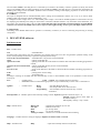
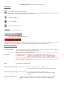
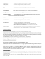
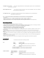
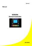
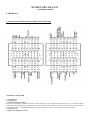
IGNIJET 2007- DUCATI
- detailed description
1. Hardware
Connection of the main connector (illustration of the unit)
"ENGINE" CONNECTOR
1. Unconnected
2. Unconnected
3. TPS throttle position sensor
The input is designed for standard TPS sensors used in motorcycles. It is designed to take voltage of 0 to 5 V. Specific settings
of the sensor for particular types of motorcycles are included in the DUCATI.EXE software. The TPS is powered by the means
of reference voltage + 5V and SENSE GND. The output of the sensor will be connected to the connector (3ENG).
4. Unconnected
5. TWS water temperature sensor
The input is designed for standard thermosensors used in motorcycles. Selection of correct sensor is carried out on the basis of
motorcycle selection in the DUCATI.EXE software. The characteristics of the sensor can be modified in the DUCATI.EXE
software. TWS will be connected to the connector (5) by one output and by the other output to the SENSE GND.
6. Unconnected
7. Unconnected
8. Unconnected
9. SM1A output for idle running control stepping motor.
10. Ignition coil IC2 (rear)
The outputs of the ignition coils are prepared for standard ignition coils for inductive ignition used in the Ducati motorcycles
(resistance of the primary coiling of the coil c. 1 to 3 Ohm).
11. Unconnected
12. Unconnected
13. Air pressure sensor APS.
The input is designed for various types of APS sensors used in motorcycles. It is designed to take voltage of 0 to 5 V. Selection
of correct is carried out on the basis of motorcycle selection in the DUCATI.EXE software. The characteristics of the sensor
can be modified in the DUCATI.EXE software. APS is powered by the means of reference voltage + 5 V and SENSE GND.
In case the APS is missing in the motorcycle system, the function of the air pressure sensing is taken over by the dashboard
that sends the information to ECU through the medium of CANbus. In case both the APS as well as dashboard are missing, the
unit sets the correction as if the air pressure is 100 kPa.
14. ATS air temperature sensor.
Option 1) The input is designed for standard thermosensors used in motorcycles. In these sensors the dependence of resistance
on temperature is generally the same as in the case of the water temperature sensors. The characteristic of the sensor can be
modified in the DUCATI.EXE software.
Option 2) The input is used for sensing of the gearbox neutral position, in this case the atmospheric air temperature values are
received by the unit from the dashboard after the CANbus.
15. Unconnected
16. Unconnected
17. SM2A output for idle running control stepping motor.
18. SM2B output for idle running control stepping motor.
19. SM1B output for idle running control stepping motor.
20. Grounding of SENSE GND sensors.
Grounding of SENSE GND sensors is used in connecting and powering of sensing components.
21. Unconnected
22. Reference voltage + 5 V.
Reference voltage + 5 V is used for powering of sensing components.
23. OILPRESS/NEUTRAL.
Option 1) The input is used for status sensing of the oil pressure switching device and the status is sent to the dashboard by the
means of CAN.
Option 2) The input is used for sensing of the gearbox neutral position and information about its status is sent to the dashboard
by the means of CAN.
24. Unconnected
25. Crankshaft position sensor CMPS.
The input is designed for standard inductive pick-up sensors used in Ducati motorcycles.
26. Unconnected
27. Unconnected
28. Main injector – frontal (INJ1)
Outputs of injectors are designed for standard injectors (on-off) used in Ducati motorcycles (coil resistance c. 13 Ohm).
29. Grounding of SENSE GND sensors.
Grounding of SENSE GND sensors is used in connecting and powering of sensing components.
30. Unconnected
31. Unconnected
32. Reference voltage + 5 V.
Reference voltage + 5 V is used for powering of sensing components.
33. Unconnected
34. Grounding of SENSE GND sensors.
Grounding of SENSE GND sensors is used in connecting and powering of sensing components.
35. Grounding of SENSE GND sensors.
Grounding of SENSE GND sensors is used in connecting and powering of sensing components.
36. Unconnected
37. Main injector – rear (INJ2)
Outputs of injectors are designed for standard injectors (on-off) used in Ducati motorcycles (coil resistance c. 13 Ohm).
38. Ignition coil IC1 (frontal)
Outputs of ignition coils are designed for standard ignition coils for inductive ignition used in Ducati motorcycles (resistance
of the primary coiling of the coil c. 1 to 3 Ohm).
"BODY" CONNECTOR
1. Output for switching of the startup contactor
Output is switched by the controlling unit if conditions for starting motorcycle are executed, that is, when neutral is engaged or
the clutch disengaged.
2. Unconnected
3. Unconnected
4. Powering voltage +12 V permanently.
5. Unconnected
6. Output for switching fuel pump relay.
After the unit is switched on, the fuel relay is switched on for approximately 4 seconds and remains switched on throughout the
entire time the motor is running.
7. Unconnected
8. Unconnected
9. "TACHO" tachometer output
The tachometer output is pulsed with open collector and can be adjusted by the means of the Ducati.EXE software. During the
activation of the TACHO/LAMBDA switching device the tachometer displays the AFR (ratio between air and fuel)
calculated from the LAMBDA probe voltage.
10. Unconnected
11. Output for ventilator switching (COOL 1/LAMBDA HEAT)
Option 1) The output is used for switching of the first cooling ventilator.
Option 2) The output is used for the lambda probe heating.
12. Unconnected
13. FI INDICATOR
The output for operating motor failure pilot light.
14. Output for ventilator COOL 2 switching
The output is used for switching of the second cooling ventilator.
15. Unconnected
16. K-LINE
Serial service communication line (not used in Ignijet Ducati).
17. + 12 V KEY
Voltage from the switch box.
18. Unconnected
19. Unconnected
20. CAN HI
CANbus outlet.
21. Unconnected
22. LAMBDA SENSOR
The input is designed both for standard lambda probes (voltage for stoichiometric mixture: 0,4 to 0,8 V) as well as linear
lambda probes with converter (UEGO, Wideband 0 – 5 V).
It is designed to take voltage of 0 to 5 V. The lambda probe voltage is not used for lambda-regulation of the mixture but only
for displaying the lambda probe voltage on the monitor in the DUCATI.EXE software or by the means of the tachometer. It is
also used in the self-tuning mode of the unit.
23. FUEL LEVEL SENSOR
Input for fuel quantity sensing. The data is sent to the dashboard by the means of CAN.
24. SPEED INPUT
The input is designed for standard Hall speed sensors used in motorcycles.
25. Unconnected
26. Unconnected
27. B+
Feeding voltage + 12 V.
Feeding voltage is nominally 14 V. It must be within the range of 8 to 16. Within this range the unit is able to control
optimally all processes.
28. START INPUT
The task of the input is to sense the startup button status and in case the above listed conditions are executed the unit will
execute the start of the motor.
29. CAN LOW
Output of CANbus.
30. Unconnected
31. Unconnected
32. SENSE GND LAMBDA
Grounding of the SENSE GND LAMBDA sensors is a sensor grounding of the lambda probe.
33. CLUTCH
The task of the input is to sense the status of the switching device on the clutch.
34. Unconnected
35. Unconnected
36. Unconnected
37. Unconnected
38. SIDESTAND
The task of the input is to sense the status of the switching device of the sidestand.
Auxiliary connector connection (on the connecting bundle)
1
2
3
4
5
6
7
8
9
GEAR SHIFT LIGHT
N2O
START LIMITER
POT
+5V
CLUTCH MASTER
TACHO/LAMBDA
LAMBDA
SENSE GND
BLACK
VIOLET
GREY
WHITE
RED
ORANGE
YELLOW/GREEN
BROWN
BLUE
AUXILIARY CONNECTOR (Only in the racing version)
1. Gear shift pilot light (GEAR SHIFT LIGHT).
The gear shift pilot light output can be charged by maximum power of 5 A (a bulb up to 50 W). The gear shift pilot light
revolutions are set in the DUCATI.EXE software.
The gear shift pilot light is connected by one outlet to the auxiliary connector (position 1) and by the second outlet on the
switched +12V.
2. Output for nitrous oxide dosing
Output for the N2O dosing valve can be charged by maximum power of 10 A (only for a short time – c. 30 seconds). The N 2O
dosing is subject to the following conditions: TPS > 85%, revolutions higher than 2000 per minute, permission in the
DUCATI.EXE software) and it is delayed after the use of START LIMITER. Setting of the N2O increase, the RETARD
increase delay after the start is set in the DUCATI.EXE software. The N2O dosing valve is connected by one outlet to the
auxiliary connector (position 2) and by the second on the switched +12 V.
BE EXTREMELY CAREFUL IF THE ELECTROMAGNETIC VALVE IS CONNECTED DIRECTLY TO THIS
OUTPUT! IT IS ALWAYS NECESSARY TO BRIDGE IT WITH THE so called ZERO DIODE!
3. The start limiter input (START LIMITER)
The switching device START LIMITER is connected by one outlet to the auxiliary connector (position 3) and by the second
outlet to the SENSE GND or GND (grounding). If START LIMITER switching device is activated, the unit sets the start
limiter and after deactivation of the START LIMITER switching device it activates delay in N 2O dosing. Opposite polarity of
the START LIMITER switching device can be configured in the DUCATI.EXE software.
4. Correction potentiometer POT
The correction potentiometer voltage can adjust the fuel map, ignition advance map, or set the start limiter value. Correction
voltage is 0 to 5 (zero correction is always in 1/2 [c. 2,5 V]) of reference voltage. Specific setting of corrections is included in
the DUCATI. EXE software.
POT is poweredby the means of reference voltage + 5V (position 5 of auxiliary connector) and SENSE GND (position 9 of the
auxiliary connector). Potentiometer output (sliding contact) will be connected to position 4 of the auxiliary connector.
5. Reference voltage + 5V
Reference voltage + 5 V (position 5 of the auxiliary connector) is used for powering of sensing components.
6. Input CLUTCH MASTER
The CLUTCH MASTER switching device is connected by one outlet to the auxiliary connector (position 6) and by the second
outlet to SENSE GND or GND (grounding). If the CLUTCH MASTER switching device is activated, the unit blocks the
ignition for specified time. This allows to shift gear to higher speed level without clutch and without throttling back and
therefore minimise time delays during gear shifting. The blockage time can be set by the DUCATI.EXE software. Opposite
polarity of the CLUTCH MASTER switching device can be configured in the DUCATI.EXE software.
7. Switching input of TACHO/LAMBDA
The TACHO/LAMBDA switching device is connected by one outlet to the auxiliary connector (position 6) and by the second
outlet to the SENSE GND or GND (grounding). If the TACHO/LAMBDA switching device is activated, the unit displays the
lambda probe voltage on the tachometer (instead of the revolutions). Setting of the display proportions is carried out on the
MOTORCYCLE bookmark.
8. LAMBDA
The input is designed both for standard lambda probes (voltage for stoichiometric mixture: 0,4 to 0,8 V) as well as linear
lambda probes with converter (UEGO, Wideband 0 – 5 V).
It is designed to take voltage of 0 to 5 V. The lambda probe voltage is not used for lambda-regulation of the mixture but only
for displaying the lambda probe voltage on the monitor in the DUCATI.EXE software or by the means of the tachometer. It is
also used in the self-tuning mode of the unit. Be warned that this outlet is internally connected with pin 22 of the BODY
connector. In case there is lambda sensor (newer types) in the original wiring (newer types), this input cannot be used!
9. SENSE GND
Grounding of the SENSE GND sensors (position 9 of auxiliary connector) is used in connecting and powering of sensing
components.
1. DUCATI.EXE software
Pull down menu
File – includes items:
New
- sets default data
Warning!!!This serial setting sets most parameters for specific motorcycle but it does not guarantee optimum running of the
motor. It will probably be necessary to optimise especially the fuel maps.
New for the current bookmark - sets default data only for the current bookmark
Open
- opening of the data file
Open from exe dir
- opening of the data file in the folder in which the DUCATI.EXE controlling programme is
located
Open for the current bookmark - opening of the data file only for the current bookmark
Save
- saving of the data file
Save in exe dir
- saving of the data file in the folder in which the DUCATI.EXE controlling programme is
located
Print
- printing of the current setting
End
- programme end
Warning!!! Clicking on the New item will automatically set the so called default values in all parameters of the selected
motorcycle.
Port
- includes items:
Com1 – Com 20 – the communication line selection
- Com Auto selection will find the appropriate Com port automatically if active unit is connected to it.
Ignition
-
includes items:
Read
Verify
Programming
- will read data from the unit
- will compare data in PC and in the unit
- will send data to the unit and will carry out their
verification
Fuel injection 1,2 – includes options of the TP maps settings control: Separate (separate control for maps 1, 2)
Ganged (ganged control of the maps by
the means of map 1)
1=2 (equality of maps – map 1 used)
Help– includes items:
Minus (F4)
Plus (F5)
Back
Redo
Tuning on-off (F6
- reducing the parameter by one unit
- addition of one unit
- go one step back
- go one step forward
- switches on or off the automatic fuel self-tuning
Language – includes items for setting of language: English, German, French and Czech
Help – includes items:
Help
- opens the Assembly instructions (this file)
About the programme – programme data (version, date)
Icon menu
- sets default values of selected motorcycle
Warning!!! This serial setting sets most parameters for specific motorcycle but it does not guarantee optimum running of the
motor. It will probably be necessary to optimise especially the fuel maps.
- opening of data file
- saving of data file
- printing of the current setting
Undo and Redo help
- please see the pull down menu of the Device
THERE IS NOT CONNECTION PC- information about the communication status; if this sign is displayed, the unit is not
connected, or its powering voltage is not switched on, or the communication port is not selected correctly.
Motorcycle bookmark
Motorcycle selection
- selection of specific motorcycle; the selection will set number of quantities and links among them.
These are related to the setting for specific motorcycle.
Warning!!! When new type of motorcycle is selected, the software will offer to set in all parameters the so called
default values of the selected motorcycle.
Dwell time
- determines how long will the ignition coil be energised during POWERING by 12 V.
It is generally set for
- ignition coils with resistance of c. 3 ohm
dwell time 3000 uS
-ignition coils with resistance of c. 1 ohm
dwell time 1900 uS
These times are predefined for individual types of motorcycles and interference with this constant
should be carefully considered because an unsuitable constant could result in damaging of outputs of
the controlling unit and ignition coils!
Note
- text field for the user note record
Function of the Engine 23 pin – defines function of pin 23 in the engine connector; the pin can serve as
the oil pressure sensor or as the sensor of the neutral engagement.
Function of the Engine 14 pin – defines function of pin 14 in the engine connector; the pin can serve
as the atmospheric pressure sensor or as the sensor of the neutral
engagement.
Function of the Body 11 pin
- defines function of pin 11in the body connector; the pin can serve as an output for
the FAN 1 ventilator switching or as an output for controlling the lambda probe
heating.
Cooling (Fan 1)
- temperature setting for switching ventilator 1 - cooling
Cooling (Fan 2)
- temperature setting for switching ventilator 2 - cooling
RPM
- mode selection and setting of the output correction for the tachometer
No fuel indication
Blocking enabled
- ticking this field will prevent displaying of the minimum fuel on the dashboard
- determines whether blocking by sidestand will be used
Activation by switching
- setting of the input logic (if the field is ticked, the appropriate function is activated by
connecting of the appropriate input to the grounding)
Limiters
- mode selection and value setting for the revolution limiter
Start limiter min
- minimum value setting for the revolution start limiter
Start limiter max
- maximum value setting for the revolution start limiter
- setting between minimum and maximum value will be carried out by the
means of voltage of 0 to 5 V in the POT input. If no voltage is led to this input,
minimum value of start limiter is realised.
Lambda on RPM
- these settings determine what revolutions will be displayed in the mode of lambda ratio
display by tachometer (input TACHO/LAMBDA is switched to lambda).
Advance bookmark
The advance map includes 15 adjustable revolution points x 10 points of the throttle opening.
Collective setting of the whole column can be carried out by the means of cursors under the columns. Collective setting of the
whole map can be carried out by the means of the collective change help(cursor at the bottom right corner with the option All).
When the PC is connected with the unit during the running of the motor, the current segment is highlighted in the advance
map. This segment can also be modified by the F4 and F5 keys. When the collective change help (cursors at the bottom right
corner without the option All) is used, only the current segment will be changed.
The Base advance value mechanically defines the given basic (minimum, startup) advance.
Cells in the bottom part of the map serve for the purpose of correction of individual cylinders.
Injection 1, Injection 2 bookmarks
TP map serves for setting of fuel supply in the entire load range.
TP map includes 15 adjustable revolution points x 10 points of the throttle opening.
Collective setting of the entire column can be carried out by the means of cursors under the columns. Collective setting of the
whole map can be carried out by the means of the collective change help (cursors at the bottom right corner with the option
All).
When the PC is connected with the unit during the running of the motor, the active segment is highlighted in the fuel map. This
segment can also be modified by the F4 and F5 keys. When the collective change help (cursors at the bottom right corner
without the option All) is used, only the current segment will be changed. In case we want the change to be carried out online,
it is necessary to click on the “programming after the change” option.
Position bookmark
The injection position is defined here. The curve includes 15 adjustable points in relation to the revolutions. The position is
defined by the angle before the top dead centre of the working stroke. Selection can be made of the position of the start, middle
or end of the injection.
Collective setting of the whole curve can be carried out by the means of the collective change help (cursors at the bottom part
with the option All).
When the PC is connected with the unit during the running of the motor, the current segment is highlighted in the fuel map.
When the change help (cursors at the bottom part without the option All) only the current segment will be changed.
Correction bookmark
Correction after start
- here the after start enrichment can be selected at the “cold start”. Modified can be both the time
curve (Time) as well as the enriching value curve. The after start enrichment values are indicated
for the water temperature - 10°C. For higher temperatures the after start enrichment values linearly
decrease and for the water temperature that is higher than 80°C they equal 100 (no enrichment).
Start injection asynchronous injection into all cylinders during the starting of the motor (for the motor temperature
80°C – at lower temperatures it is extended accordingly).
Acceleration injection
- asynchronous injection into all cylinders at the moment of required acceleration (acceleration
pump).
Threshold
- minimum speed of the throttle motion for activating the acceleration
injection
Size
– duration of individual acceleration injections (the period is 10 ms)
Injections are taking place for the duration of the throttle motion
Temperature correction of the injection
Water temperature
- correction curve of the motor temperature (100% means default setting at 80°C)
Air temperature during suction – correction curve of the air temperature (100% means default setting at 50°C)
Acceleration correction of the injection
- defined here is the acceleration correction of the injection (its sensitivity and duration response) during rapid change in the
load on the motor (during rapid movement of the throttle). During rapid opening of the throttle, the rapid change in the suction
pressure causes enleanment of the mixture entering the motor. Situation during rapid closure of the throttle is similar but with
the opposite effect – it results in the the enrichment of the mixture. The task of the acceleration correction is to correct these
undesirable dynamic changes. These phenomena are significantly manifest especially in the lower levels of load on the motor.
Current value of all injection corrections:
Starting correction
after start correction
U correction
injection correction from the voltage
TW correction
injection correction from the water temperature
AT correction
injection correction from the air temperature
AP correction
injection correction from the atmospheric pressure
POT correction
injection correction from the correction potentiometer
ACC correction
acceleration correction of the injection
Current value of all advance corrections:
TW correction
advance correction from the water temperature
POT correction
advance correction from the correction potentiometer of injection
IDLE
advance correction from the regulator of idle revolutions
Thermal correction of the advance
- correction curve of the advance from the motor temperature
Sensors bookmark
TPS
- the ultimate TPS voltage [mV] values can be set here
- will measure and set 0% TPS (switched on feeding, unit connected with PC,
with throttle closed)
- will measure and set 100% TPS (switched on feeding, unit connected with PC, full throttle)
Atmospheric pressure sensor
- the pressure-voltage characteristics of the atmospheric pressure sensor can be defined here
by the means of two points.
Water temperature sensor
- the temperature-voltage characteristics of the water temperature sensor can be defined
here by the means of nine-point curve.
Air temperature sensor - the temperature-voltage characteristics of the air temperature sensor can be defined here
by the means of nine-point curve.
POT – selection of mode and size of the maximum correction from the correction potentiometer
- no correction
- injection correction (0 to 5 V voltage corresponds with the correction –Range to +Range in %)
- advance correction (0 to 5 V voltage corresponds with the correction –Range to +Range in °)
- setting of the Start limiter (0 to 5 V voltage corresponds with the setting of Start limiter min to Start limiter max)
Idle running bookmark
Idle running regulation
- none, no regulation of the idle running by-pass air is carried out
- stepping motor without potentiometer; carried out is the regulation of the idle running by-pass air to the target revolutions
according to the motor temperature (it is set in the column in the middle of the bookmark)
- reverse running of the motor; changes the stepping motor turning direction
- stepping motor dwell time; it sets the stepping motor turning moment
- stepping motor period; it sets the sweeping speed of the stepping motor
- start; duration of time for which the stepping motor is running after the unit is switched on (moderate increase of the air
before the start)
- column of required revolution values for individual temperatures (interpolation is carried out between individual points)
-idle running regulation by the advance; here the regulation of idle running can be carried out by the means of change of the
advance
- range [rpm]; it is a rpm value up to which it is possible to carry out regulation of idle running (applicable for both kinds of
regulation)
- regul range TPS x 10 [%]; it is a value in tenths of % TPS up to which it is possible to carry out the idle running regulation is
(applicable for both kinds of regulation)
- Hysteresis [rpm]; it determines the dead zone on the regulation deviation (applicable for both kinds of regulation)
N2O bookmark
N2O permitted
- the software activation of the N2O dosing controller
N2O
N2O 1
N2O
Increase
Advance reduction
- initial flow of N2O
- final flow of N2O
- duration of increase from the initial to the final flow of
gas
Delay
- duration of delay after the start limiter of revolutions was
activated
Correction - injection 1 – initial correction of injection from N2O
Correction - injection 2 – final correction of injection from N2O
Advance reduction 1
Advance reduction 2
Increase
Delay
- initial advance reduction
- final advance reduction
- increase duration from the initial to the final advance
reduction
- duration of delay after the start limiter of revolutions was
activated
Race bookmark
Clutch mode
Min clutch RPM
Clutch inj.
Clutch advance
- defines the method of clutch master (by omission of ignition or by advance reduction)
- minimum revolutions needed for activation of the clutch master
- percentage quantity of fuel during the running of clutch master
- advance during the clutch master running (in the clutch master mode of “ignition
delay”)
Setting according to the shifted gear – values of several parameters can be set here that depend
on the shifted gear
Gear shift pilot light
Clutch master
Clutch master pause
- two-step gear shift pilot light (during the first level revolutions it will start to flash and during the
final level it will be continually lit)
- setting of the clutch master duration
- setting of period during which, after the clutch master activation, the
clutch master cannot be
activated again
Gear shift bookmark
Determination of speed
- it defines the way of determining the shifted gear
Ratio of RPM/speed
- determination by the means of the ratio of RPM/speed calculation with manual entry
Automatic - ratio of RPM/speed - determination by the means of the ratio of RPM/speed calculation with automatic search
Quantity of gears
- here it is necessary to enter the quantity of motorcycle gears (except neutral)
Ratio of RPM/speed
- entering of the RPM/speed ratio for individual gears, setting fields on the right hand side
serve the purpose of manual inputting of the ratio values
Automatic - ratio of RPM/speed - parameters for automatic search of the RPM/speed ratio
Speedometer
Number of pulses
Distance
Correction
- setting of the speed sensor
- number of pulses in 1 second for 100 km/h (suitable for higher number of pulses – for example
of the sensor in the gearbox)
- distance between individual pulses in millimetres (suitable for small number of pulses – for
example one per wheel revolution)
- advance and injection times can be corrected depending on the shifted gear
Self-tuning bookmark
Tuning switched on
- this indication switches on or switches off the automatic self-tuning of the active fuel maps. This
function can also by controlled by the F6 key.
Self-tuning method
In points
- in this mode only self-tuning of one point is carried out provided the motor has
appropriate revolutions and throttle position .
than the “Rpm tolerance” and the valve/throttle position, or IAP pressure is closer than “Tps,
Iap tolerance”.
Everywhere – in this mode four neighbouring points in the active fuel map are tuned in such proportion
that corresponds with the approximation of the point and the real value.
Rpm tolerance
TPS tolerance
- it is the deviation value of revolutions when the self-tuning in the mode “In points” is switched on
or switched off.
- it is the deviation value of the throttle position when the tuning in the mode
“In points” is switched on or switched off.
A/F [x 10]
- it is the target value of the air/fuel ratio that the unit must achieve during correction while the selftuning is switched on. It is entered in the AFR tenths (145 = AFR 14,5). Be aware that the type and
characteristics of the lambda sensor must be correctly set in the Sensors bookmark!
A/F tolerance[x 10]
- it is the AFR value deviation (in the AFR tenths) when the tuning is switched on or switched off.
Stepping time [mS]
- it is the value of frequency indicating how often the correction will be carried out.
Step [%]
- it is the value indicating by how many % in one step will the individual points be corrected.
Max Acc Kor [%]
- it is the value of the acceleration correction limit when the tuning is switched on or switched off.
Monitor bookmark
Injection
Input earthing
Advance
Detailed display
- detailed values of injection times of the individual injectors
- detection of switching of individual switching inputs
- detailed advance values of individual cylinders
- extended monitor mode switching. In this mode the monitor will also display the voltage of
individual sensors and other parameters.
- there are also listed values and status of other functions of the unit
Monitor
The monitor is located at the bottom part of the programme; the values of sensors and operational values of the motor can be
observed here.
RPM
TP
LAMBDA
TW
AT
AP
Fuel
U
Advance
Max injection
Injection A
Sensor CMPS
Blocking
Speed
Programming after change
Prohibition of reading
Gear
Ventilator 1
Ventilator 2
Start button
Clutch
- motor revolutions [1/min]
- throttle position [%]
- measured voltage of lambda probe [mV]
- water temperature [°C]
- air temperature [°C]
- atmospheric pressure [kPa]
- fuel level in the tank
- feeding voltage of the injectors [V]
- ignition advance [°]
- displaying of the time filling factor of the injection cycle [%]
- time of the injection of primary injector [µs]
- detection of pulses of the cam-shaft position sensor
- signaling of the blocking activation
- display of current speed
- automatic unit programming option
- option of prohibition of reading from the unit
- displaying of the currentlyshifted gear
- displaying of the current status of the fan 1 output
- displaying of the current status of the fan 2 output
- displaying of the current status of the start input
- displaying of the current status of the clutch input
Neutral
Boční stojánek
- displaying of the current status of the neutral input (either from ATS or OILPRESS)
- displaying of the current status of the sidestand input
3. Connection for individual motorcycles
Standard design uses 2x connector Cinch 38pin.
The unit is made in two hardware versions:
A) FULLVERSION – includes all functions listed in this document.
B) BASIC VERSION – it does not include inputs/outputs for racing: CLUCH MASTER, START LIMITER,
TACHO/LAMBDA, GEAR SHIFT LIGHT, N2O.