1
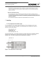
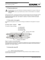
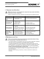
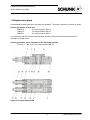
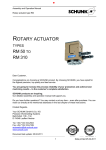
Assembly and Operation Manual
Rotary actuator type RM
ROTARY ACTUATOR
TYPES
RM 12 TO
RM 21
Dear Customer,
Congratulations on choosing a SCHUNK product. By choosing SCHUNK, you have opted for
the highest precision, top quality and best service.
You are going to increase the process reliability of your production and achieve best
machining results – to the customer's complete satisfaction.
SCHUNK products are inspiring.
Our detailed assembly and operation manual will support you.
Do you have further questions? You may contact us at any time – even after purchase. You can
reach us directly at the mentioned addresses in the last chapter of these instructions.
Kindest Regards,
Your SCHUNK GmbH & Co. KG
Precision Workholding Systems
Bahnhofstr. 106 - 134
D-74348 Lauffen/ Neckar
Tel. +49-7133-103-2503
Fax +49-7133-103-2189
[email protected]
www.schunk.com
Document last update: 18.02.2008
1
Date printed 23.02.2010
Assembly and Operation Manual
Rotary actuator type RM
Contents
1
SAFETY ................................................................................................................................................. 3
1.1
1.2
1.3
1.4
SYMBOL KEY .................................................................................................................................... 3
APPROPRIATE USE .......................................................................................................................... 3
SAFETY NOTES ................................................................................................................................ 3
INDICATIONS TO THE OPERATING MANUAL ......................................................................................... 4
2
WARRANTY .......................................................................................................................................... 4
3
SCOPE OF DELIVERY ......................................................................................................................... 5
4
TECHNICAL DATA ............................................................................................................................... 5
5
OPERATING AND ENVIRONMENTAL CONDITIONS......................................................................... 5
6
ASSEMBLY AND INSTALLATION ....................................................................................................... 5
6.1
6.2
6.3
6.4
6.5
7
DESIGN PRECAUTIONS ..................................................................................................................... 5
COMPRESSED AIR SUPPLY ................................................................................................................ 6
SPECIAL CONNECTING MEASURES..................................................................................................... 6
ASSEMBLY MEASURES...................................................................................................................... 6
MEASURES FOR THE INITIAL OPERATION............................................................................................ 6
HANDLING ............................................................................................................................................ 7
7.1
FINE ADJUSTMENT OF ROTATION ANGLE ............................................................................................ 7
7.2
DAMPING ADJUSTMENT .................................................................................................................... 8
7.3
END POSITION INTERROGATION ........................................................................................................ 8
7.4
INTERMEDIATE STOPS RZ................................................................................................................. 8
7.4.1
Setting of intermediate position.............................................................................................. 8
7.4.2
Damping adjustment .............................................................................................................. 9
7.4.3
Interrogation of intermediate position..................................................................................... 9
8
REPAIRS ............................................................................................................................................... 9
9
RESPONSE TO MALFUNCTIONS ..................................................................................................... 10
10
MAINTENANCE AND CARE............................................................................................................... 10
11
REPLACEMENT PARTS .................................................................................................................... 11
12
INDEX .................................................................................................................................................. 12
13
EC DECLARATION OF INCORPORATION ....................................................................................... 13
14
CONTACT ........................................................................................................................................... 14
2
Date printed 23.02.2010
Assembly and Operation Manual
Rotary actuator type RM
1 Safety
1.1 Symbol key
You will find this symbol wherever hazards for persons or damage to the product
are possible.
This symbol indicates important information on the product or its handling.
1.2 Appropriate Use
The rotary actuators are manufactured in accordance with the current level of technology and
with recognised safety regulations. During their use, however, there may occur risks to life and
limb of the user or impairment of the rotary actuator and other material assets.
The rotary actuators are intended exclusively for the swivelling movement of service loads in
any position that do not react in their manipulation with any risk to persons, property or the
environment.
The maximum permissible service loads and forces are given in our standard catalogue.
Any usage beyond these definitions is inappropriate.
The manufacturer cannot be held liable for loss or damage arising therefrom. The risk is borne
exclusively by the user.
Usage in accordance with directions includes observation of the user manual as well as
adherence to the maintenance and repair specifications prescribed by the manufacturer.
The rotary actuator must only be operated by persons that are familiar therewith and that have
been instructed in the associated hazards. The relevant accident prevention regulations and the
other generally recognised safety and occupational health regulations must be complied with.
1.3 Safety Notes
1.
Responsibility for the compatibility of pneumatic equipment lies with the person
who designs the pneumatic system or takes the decision on its specifications.
Since the products specified herein can be used under various operating
conditions, their compatibility with the appropriate pneumatic system must
be based on specifications and/or tests in order to conform to their
requirements.
3
Date printed 23.02.2010
Assembly and Operation Manual
Rotary actuator type RM
2.
Machines and equipment operated by pneumatic means may only be used by
trained personnel.
Compressed air can be hazardous if an operator is not familiar with its use.
The assembly, handling or repair of pneumatic systems is to be undertaken
by trained and experienced personnel.
3.
Do not carry out maintenance work on machines and equipment and do not attempt to remove components until it has been confirmed that it is safe to do so.
Inspection and maintenance of machines and equipment may only be carried
out after it has been confirmed that the devices that must be switched off are
in a securely deactivated condition.
If machine parts must be removed, carry out safety precautions as mentioned
above. Deactivate the compressed air supply to this machine and release any
remaining compressed air from the system.
Before machines and equipment are switched on again, take measures to
ensure that cylinder rods etc. are not pushed outwards. Allow compressed air
to enter the system slowly so that counterpressure builds up gradually.
4.
Contact SCHUNK (see chapter 13 page 13) if the product is to be used under one
of the following conditions:
Conditions and environments that lie outside the stated specifications, or
where the product is to be used outdoors.
Installation in equipment in conjunction with nuclear power, railways, aerospace, vehicles, medical equipment, food and drink, leisure equipment,
emergency shutdown circuits, applications in presses or safety equipment.
Any application that may possibly have negative influences on persons, animals or property and that requires a special safety analysis.
5.
This user manual should always be easily accessible
1.4 Indications to the operating manual
This user manual describes gripper actuators of series RM 12, RM 15 and RM 21.
All statements in this user manual refer to the types stated above.
2 Warranty
The warranty period is 24 months or 40 million load cycles after delivery date from the factory,
assuming use in single-shift operation and that the recommended maintenance and lubrication
intervals are respected. Components that come into contact with workpieces, wearing parts,
shock absorbers, stop screws and proximity switches are never included in the warranty.
The warranty covers the replacement or repair of defective parts in the manufacturing plant.
Further claims are hereby excluded. In this context, please also see our General Terms and
Conditions.
4
Date printed 23.02.2010
Assembly and Operation Manual
Rotary actuator type RM
3 Scope of Delivery
The scope of delivery comprises:
Rotary actuator type RM, depending on the version ordered
4 Technical Data
Please consult our catalogue for further technical details. The last version is valid in each case.
(in accordance with Chapter 2.3 General Terms and Conditions)
The airborne sound emitted from the unit is <= 70dB(A)
5 Operating and environmental conditions
-
-
Do not use the product in environments comprising corrosive gases, salt water, water
or vapours.
For use in an atmosphere where water drops, oil, sprays etc, occur take appropriate
countermeasures in order to ensure protection.
If electronic end switches are to be used, these should not be used in the presence of
strong magnetic fields. Please contact SCHUNK (see chapter 13 page 13) if the product is to be used in the presence of strong magnetic fields.
Do not use the rotary actuator in an atmosphere in which it could come into contact
with fluids such as oil or water.
Do not use the rotary actuator in an atmosphere in which it could come into direct contact with substances such as powder dust, dust, sprays etc.
Do not use the rotary actuator in an atmosphere in which sources of heat are
present.
Do not subject the rotary actuator to excessive vibrations and/or shocks.
6 Assembly and Installation
6.1 Design precautions
-
A protective guard is recommended in order to minimise the risk of injury.
Ensure that loose, fixed and/or connected parts or tightened securely.
Operation without the shock absorbers included as standard in the scope of delivery is
not permissible.
Take account of the possibility that the operating pressure may decrease as a result
of power failures etc.
Pay attention to the possibility of the failure of power supplies.
Mount the compressed air supply in such a way as to prevent a gripping action.
Pay attention to emergency shutdown facilities.
Pay attention to what will happen after an emergency stop or abnormal stoppage.
Ensure that nobody can be placed at risk or be injured when equipment is restarted.
5
Date printed 23.02.2010
Assembly and Operation Manual
Rotary actuator type RM
6.2 Compressed air supply
-
Use clean compressed air and insert a filter between the supply and the pneumatic
system.
Install a water separator in the pneumatic system.
Use the product only within the range specified for the medium temperature and
ambient temperature.
Air specification
-
dry (free from condensation)
filtered to 10 microns
oiled or oil-free
6.3 Special connecting measures
-
Use connecting pipes of a cross-section that is larger than or identical to that of the
connector thread.
Blow air through the connecting pipes before fitting the devices in order to remove any
dust, contaminant or particles.
Avoid the ingress of sealing material into the pipe network.
Do not remove pneumatic components from their packaging until shortly before fitting.
6.4 Assembly measures
-
During the mounting of loads, do not allow the system to be subjected to
impermissible forces or moments.
The flatness of the mounting surfaces must be less than 0.02mm.
Select the correct means of connection with a load that has its own guidance
mechanism and ensure that this is adequately aligned.
Avoid contact with the rotary actuator during operation.
Select a suitable screw tightening torque for mounting of the rotary actuator or loads
on the rotary actuator in accordance with the generally valid guidelines for screw connections.
6.5 Measures for the initial operation
Please read this user manual carefully. Knowledge of this user manual is essential in
order to prevent errors and ensure problem-free operation.
Under no circumstances may rotary actuators be operated with oiled air if they
are subsequently to be operated with oil-free air.
-
Check the technical specifications.
Do not use the device until you have checked that it functions correctly taking
account of all permissible operating parameters.
6
Date printed 23.02.2010
Assembly and Operation Manual
Rotary actuator type RM
-
Regulate the operating speed of the cylinder by means of throttle type non-return
valves. Increase from the low speed to higher speeds until the required operating
speed is reached.
Selection and dimensioning
-
-
Do not subject the units to loads that exceed the limits of their operating range. If
excessive loads are applied , the gripper jaw guidance system and closing mechanism
could suffer damage or inaccuracies. The maximum permissible loads are given in our
standard catalogue.
Do not allow the system to experience impermissible forces or shocks.
7 Handling
7.1 Fine adjustment of rotation angle
For fine adjustment of the rotation angle and matching of the end damping to the mass
moment of inertia occurring in operation, the following parts are included in the scope of
delivery of each rotary actuator.
-
Stop collar (Pos. 10)
Locknut (Pos. 11)
Locknut (Pos. 12)
Shock absorber (Pos. 18)
Once the locknut (Pos. 11) has been loosened, the rotation angle can be steplessly adjusted
between 0 and 180 degrees by turning the stop collar (Pos. 10) with the integral shock
absorber (Pos. 18). Each end position can be adjusted by 90 degrees.
Figure 1: Fine adjustment of rotation angle
7
Date printed 23.02.2010
Assembly and Operation Manual
Rotary actuator type RM
7.2 Damping adjustment
Operation without the shock absorbers included as standard in the scope of delivery is
not permissible.
Please note the maximum permissible mass moment of inertia stated in our standard
catalogue.
After the locknut (Pos. 12) has been loosened, the stroke length of the shock absorber and thus
the damping curve can be matched to the mass moment of inertia occurring in operation by
rotating the shock absorber (Pos. 18) inwards or outwards. This does not affect the rotation
angle set previously.
7.3 End position interrogation
Standardised interrogation sets for direct mounting are available for interrogation of end positions.
Proximity switch - complete
RMNS-...
The scope of delivery includes:
-
1x retaining plate
2x switching cam
2x proximity switch
2x connection cable
proximity switch RMNZ
proximity switch RMNS
Figure 2: position of proximity switch
After the clamping screw has been loosened, the switching cam can be steplessly adjusted in a
vee-shaped slot in the turntable. The specific end position interrogation can thus be precisely
adjusted for each rotation angle set.
7.4 Intermediate stops RZ
7.4.1
Setting of intermediate position
Intermediate stops are additional modules for rotary actuators and are available for all rotary
actuator sizes of this series.
8
Date printed 23.02.2010
Assembly and Operation Manual
Rotary actuator type RM
RZ 12: DIN 433-3.2-ST (max. 2mm)
RZ 15: DIN 433-3.2-ST (max. 2mm)
RZ 21: DIN 126-5.5-ST (max. 5mm)
Figure 3: Rotary actuator shown in intermediate position at 90°
The intermediate position can be set at any point over the entire swivel range of the rotary actuator. It must be noted that the toothed racks of rotary actuators are tensioned without backlash where a controlled intermediate stop is used. For an intermediate position of 90 degrees or
more, the stop cylinders must be changed over.
The intermediate position is set by rotating the complete stop cylinders inwards or outwards.
The locknut (Pos. 5) must first be loosened and must be tightened again afterwards.
7.4.2
Damping adjustment
The stroke of the shock absorber and thus the damping curve can be matched to the mass
moment of inertia occurring in operation by inserting shims under the shock absorber (Pos. 9).
The stop sleeve (Pos. 2) with theh shock absorber (Pos. 9) and piston (Pos. 3) must be
dismantled first.
7.4.3
Interrogation of intermediate position
For interrogation of the intermediate position, the interrogation set RMNZ-... is available. This
interrogation set is identical with the end position interrogation set RMNS-... but contains only
one switching cam, proximity switch and connection cable and is mounted on the opposite side.
8 Repairs
The repair or elimination of defects on our products by the customer may only be
carried out with our explicit written agreement. Any failure to adhere to this principle
renders invalid our warranty and liability for any resulting warranty or secondary losses.
Following receipt and examination, all linear actuators of series RM can be repaired by
SCHUNK.
9
Date printed 23.02.2010
Assembly and Operation Manual
Rotary actuator type RM
9 Response to malfunctions
Malfunctions that are caused by defective components may only be remedied by
replacement of these components.
Defective components may only be replaced by SCHUNK genuine replacement parts.
Malfunction
Actuator does not
rotate
End position signal not present
Actuator impacts
on end positions
Service load
vibrates in end
position
Cause
(1) No compressed air
(2) Incorrect pneumatic
connections
Remedy
(1) Check compressed air
(2) Check pneumatic elements
(1) Initiator incorrectly set in
relation to stop
(2) Initiator defective
(3) Broken cable
(1) Readjust initiator
(1) Damping incorrectly
adjusted
(2) Shock absorber defective
(3) Ventilation valve defective
(4) Rotation speed too high
(1) Adjust stop screw
(1)
(2)
(3)
(4)
(1)
(2)
(3)
(4)
Rotation speed too high
Inadequate damping
Unfavourable installation
Unfavourable RM type
(2) Replace initiator
(3) Replace initiator cable
(2) Change shock absorber
(3) Check ventilation valve
(4) Set ventilation valve
Set ventilation valve
Optimise damper stroke
Check design
Use larger RM type
10 Maintenance and Care
Under no circumstances may rotary actuators be operated with oiled air if they
are subsequently to be operated with oil-free air.
-
-
-
The integral cylinders are lubricated for life and do not require relubrication. Operation
with oiled or oil-free compressed air is permissible without restrictions.
The bearing arrangements of the turntable and of the toothed rack pinion unit are
already lubricated. It is not therefore necessary to lubricate these again before operation. Lubrication or relubrication of the toothed rack pinion unit with rolling bearing
grease is recommended after approx. 4 million cycles.
All rotary actuators of series RM are maintenance-free. In order to achieve the maximum operating life, this chapter and chapter 6.2 (at page 6) of this user manual
should be observed.
Apart from normal cleaning of machines, no further maintenance measures are
necessary.
10
Date printed 23.02.2010
Assembly and Operation Manual
Rotary actuator type RM
11 Replacement parts
As standardised wear part sets, seal sets are available. The scope of delivery includes all seals.
Ordering numbers of seal sets:
RMDI 12
for rotary actuator RM 12
RMDI 15
for rotary actuator RM 15
RMDI 21
for rotary actuator RM 21
In accordance with the section drawing below, all other wear parts and individual parts are
available as single items.
Ordering numbers are as indicated in the following example
Part No. 1 RM 15-01 (for rotary actuator RM 15)
Figure 4: section drawing RM
11
Date printed 23.02.2010
Assembly and Operation Manual
Rotary actuator type RM
12 Index
A
H
Air specification ...........................6
Assembly ......................................5
Assembly measures ......................6
Handling ...................................... 7
C
compressed air ............................10
Compressed air supply .................6
connecting measures ....................6
Indication
operating manual .................... 4
initial operation............................ 6
intermediate position ................... 9
Intermediate stops ........................ 8
D
M
Damping adjustment ....................9
Data
technical ..................................5
Design precautions .......................5
dimensioning ................................7
Machine directive
EC Machine Directive .......... 12
Maintenance and Care ............... 10
malfunctions .............................. 10
I
Replacement parts ...................... 11
rotation angle ............................... 7
S
Safety ........................................... 3
Safety Notes ................................. 3
Scope of delivery ......................... 5
seal sets ...................................... 11
Symbol key .................................. 3
T
Terms and conditions
general ..................................... 4
U
Use
appropriate .............................. 3
O
E
W
Operating ..................................... 5
EC Machine Directive ................12
End position interrogation ............8
environmental conditions .............5
R
Warranty ...................................... 4
wear parts ................................... 11
Repairs ......................................... 9
12
Date printed 23.02.2010
Assembly and Operation Manual
Rotary actuator type RM
13 EC declaration of incorporation
In terms of the EC Machinery Directive 2006/42/EC, annex II B
Manufacturer/
distributor
SCHUNK GmbH & Co. KG.
Spann- und Greiftechnik
Bahnhofstr. 106 – 134
74348 Lauffen/Neckar, Germany
We hereby declare that the following product:
Product designation:
Rotary modules pneumatic, swivel unit
Type designation:
RM 12…RM21
ID number:
0313000…0313015
meets the applicable basic requirements of the Directive Machinery (2006/42/EC).
The incomplete machine may not be put into operation until conformity of the machine into which the
incomplete machine is to be installed with the provisions of the Machinery Directive (2006/42/EC) is confirmed.
Applied harmonized standards, especially:
EN ISO 12100-1
Safety of machines - Basic concepts, general principles for design -- Part 1:
Basic terminology, methodology
EN ISO 12100-2
Safety of machines - Basic concepts, general principles for design -- Part 2:
Technical principles
The manufacturer agrees to forward on demand the special technical documents for the incomplete machine to state offices.
The special technical documents according to Annex VII, Part B, belonging to the incomplete
machine have been created.
Person responsible for documentation: Mr. Michael Eckert, Tel.: +49(0)7133/103-2204
Location, date/signature:
Lauffen, Germany,
January 2010
Title of the signatory
p.p.
Director for Development
13
Date printed 23.02.2010
Assembly and Operation Manual
Rotary actuator type RM
14 Contact
GERMANY – HEAD OFFICE
CANADA
DENMARK
HUNGARY
SCHUNK GmbH & Co. KG
Spann- und Greiftechnik
Bahnhofstrasse 106 – 134
D-Lauffen/Neckar
Tel. +49-7133-103-0
Fax +49-7133-103-2399
[email protected]
www.schunk.com
SCHUNK Intec Corp.
190 Britannia Road East,
Units 23-24
Mississauga, ON L4Z 1W6
Tel. +1-905-712-2200
Fax +1-905-712-2210
[email protected]
www.ca.schunk.com
SCHUNK Intec A/S
Storhaven 7
7100 Vejle
Tel. +45-43601339
Fax +45-43601492
[email protected]
www.dk.schunk.com
SCHUNK Intec Kft.
Széchenyi út. 70.
3530 Miskolc
Tel. +36-46-50900-7
Fax +36-46-50900-6
[email protected]
www.hu.schunk.com
AUSTRIA
CHINA
FRANCE
INDIA
SCHUNK Intec GmbH
Holzbauernstr. 20
4050 Traun
Tel. +43-7229-65770-0
Fax +43-7229-65770-14
[email protected]
www.at.schunk.com
SCHUNK GmbH & Co.KG
Shanghai
Representative Office
777 Zhao Jia Bang Road
Pine City Hotel, Room 923
Xuhui District
Shanghai 200032
Tel. +86-21-64433177
Fax +86-21-64431922
[email protected]
www.cn.schunk.com
SCHUNK Intec SARL
Parc d´Activités des Trois
Noyers 15, Avenue James de
Rothschild
Ferrières-en-Brie
77614 Marne-la-Vallée
Cedex 3
Tel. +33-1-64 66 38 24
Fax +33-1-64 66 38 23
[email protected]
www.fr.schunk.com
SCHUNK India Branch Office
# 80 B, Yeswanthpur
Industrial Suburbs,
Bangalore 560 022
Tel. +91-80-41277361
Fax +91-80-41277363
[email protected]
www.in.schunk.com
BELGIUM, LUXEMBOURG
CZECH REPUBLIC
GREAT BRITAIN, IRELAND
ITALY
SCHUNK Intec N.V./S.A.
Bedrijvencentrum Regio Aalst
Industrielaan 4, Zuid III
9320 Aalst-Erembodegem
Tel. +32-53-853504
Fax +32-53-836022
[email protected]
www.be.schunk.com
SCHUNK Intec s.r.o.
Ernsta Macha 1
643 00 Brno
Tel. +420-545 229 095
Fax +420-545 220 508
[email protected]
www.cz.schunk.com
SCHUNK Intec Ltd.
Cromwell Business Centre
10 Howard Way,
Interchange Park
Newport Pagnell MK16 9QS
Tel. +44-1908-611127
Fax +44-1908-615525
[email protected]
www.gb.schunk.com
SCHUNK Intec S.r.l.
Via Barozzo
22075 Lurate Caccivio (CO)
Tel. +39-031-4951311
Fax +39-031-4951301
[email protected]
www.it.schunk.com
14
Date printed 23.02.2010
Assembly and Operation Manual
Rotary actuator type RM
JAPAN
POLAND
SOUTH KOREA
SCHUNK Intec K.K.
45-28 3-Chome Sanno
Ohta-Ku Tokyo 143-0023
Tel. +81-33-7743731
Fax +81-33-7766500
[email protected]
www.tbk-hand.co.jp
SCHUNK Intec Sp.z o.o.
Stara Iwiczna,
ul. Słoneczna 116 A
05-500 Piaseczno
Tel. +48-22-7262500
Fax +48-22-7262525
[email protected]
www.pl.schunk.com
SCHUNK Intec Korea Ltd.
# 907 Joongang
Induspia 2 Bldg.,
144-5 Sangdaewon-dong
Jungwon-gu, Seongnam-si
Kyunggi-do, 462-722
Tel. +82-31-7376141
Fax +82-31-7376142
[email protected]
www.kr.schunk.com
MEXICO, VENEZUELA
PORTUGAL
SPAIN
TURKEY
SCHUNK Intec S.A. de C.V.
Av. Luis Vega y Monroy # 332
Fracc. Plazas de Sol
Santiago de Querétaro,
Qro. 76099
Tel. +52-442-223-6525
Fax +52-442-223-7665
[email protected]
www.mx.schunk.com
Sales Representative
Victor Marques
Tel. +34-937-556 020
Fax +34-937-908 692
Mobil +351-963-786 445
[email protected]
www.pt.schunk.com
SCHUNK Intec S.L.
Foneria, 27
08304 Mataró (Barcelona)
Tel. +34-937 556 020
Fax +34-937 908 692
[email protected]
www.es.schunk.com
SCHUNK Intec
Bağlama Sistemleri ve
Otomasyon San. ve Tic. Ltd. Şti.
Küçükyali Iş Merkezi
Girne Mahallesi
Irmak Sodak, A Blok, No: 9
34852 Maltepe, Istanbul
Tel. +90-216-366-2111
Fax +90-216-366-2277
[email protected]
www.tr.schunk.com
NETHERLANDS
SLOVAKIA
SWEDEN
USA
SCHUNK Intec B.V.
Speldenmakerstraat 3d
5232 BH ‘s-Hertogenbosch
Tel. +31-73-6441779
Fax +31-73-6448025
[email protected]
www.nl.schunk.com
SCHUNK Intec s.r.o.
Mostná 62
919 01 Nitra
Tel. +421-37-3260610
Fax +421-37-6421906
[email protected]
www.sk.schunk.com
SCHUNK Intec AB
Morabergsvägen 28
152 42 Södertälje
Tel. +46-8 554 421 00
Fax +46-8 554 421 01
[email protected]
www.se.schunk.com
SCHUNK Intec Inc.
211 Kitty Hawk Drive
Morrisville, NC 27560
Tel. +1-919-572-2705
Fax +1-919-572-2818
[email protected]
www.us.schunk.com
15
SWITZERLAND,
LIECHTENSTEIN
SCHUNK Intec AG
Soodring 19
8134 Adliswil 2
Tel. +41-44-7102171
Fax +41-44-7102279
[email protected]
www.ch.schunk.com
Date printed 23.02.2010