1
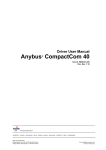
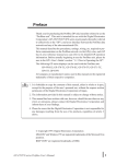
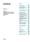
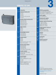
How to configure an Anybus PROFINET IO Slave module with a Siemens Step7 PLC
SCM-7032-030
Rev 1.11
How to configure an Anybus PROFINET IO
Slave module with a Siemens Step7 PLC
www.anybus.com
HMS Industrial Networks AB
Page 1 (25)
How to configure an Anybus PROFINET IO Slave module with a Siemens Step7 PLC
SCM-7032-030
Rev 1.11
More information about the network and products
The most recent manuals and GSD files for the Anybus PROFINET IO modules can be found on the HMS
webpage www.Anybus.com.
The PROFIBUS & PROFINET International has a webpage on the Internet: www.profinet.com. Several
technical guides are available in or via this page.
For information concerning the PLC and the PROFINET IO Controller system refer to the Siemens
homepage http://www.automation.siemens.com/_en/portal/index.htm
History
Revision
Date
Description
Author
1.00
2007-08-08
Created
Thorbjörn Palm
1.10
2007-12-07
Released
Thorbjörn Palm
1.11
2008-03-10
Updated layout
Thorbjörn Palm
www.anybus.com
HMS Industrial Networks AB
Page 2 (25)
How to configure an Anybus PROFINET IO Slave module with a Siemens Step7 PLC
SCM-7032-030
Rev 1.11
Contents
1.
Applicable Anybus products ...................................................................................................................4
2.
Requirements ............................................................................................................................................4
3.
Solution overview .....................................................................................................................................5
4.
PLC configuration....................................................................................................................................6
5.
PROFINET IO configuration..................................................................................................................9
5.1.
Importing the GSD file .....................................................................................................................9
5.2.
Adding the Anybus module to the configuration..............................................................................9
5.3.
Configuring the IP address and Device name .................................................................................11
5.4.
I/O configuration.............................................................................................................................14
5.5.
I/O configuration using data consistency........................................................................................16
6.
Anybus configuration.............................................................................................................................18
6.1.
Communicator configuration ..........................................................................................................19
6.2.
X-gateway configuration ................................................................................................................21
7.
Testing .....................................................................................................................................................23
Appendix .........................................................................................................................................................25
Diagnostics in Step7.....................................................................................................................................25
www.anybus.com
HMS Industrial Networks AB
Page 3 (25)
How to configure an Anybus PROFINET IO Slave module with a Siemens Step7 PLC
SCM-7032-030
Rev 1.11
1.
Applicable Anybus products
Description
Name / Type
Anybus X-gateway
PROFINET IO
Anybus Communicator
PROFINET IO
Anybus-Slave
PROFINET IO
Anybus CompactCom
PROFINET IO
Anybus-PCI
PROFINET IO
2.
Requirements
Description
Name / Type
Version
Siemens S7 PLC
CPU 315-2 DP
6ES7 315-2AF02-0AB0
Siemens PLC programming cable
n.a.
n.a.
PC with Siemens PLC programming software
Simatic Step7
5.4.1.0
GSD file for the Anybus-S Slave Interface, AnybusPCI and the X-gateway Slave Interface
GSD-V1.0-Hms-ABSPRT20070221.xml
1.0
GSD file for the Anybus Communicator
GSD-V1.0-HMS-ABCPRT20050317
1.0
GSD-file for the Anybus CompactCom
n.a.
n.a
X-gateway Network Interface Addendum
Anybus X-gateway
PROFINET IO, Network
Interface Addendum
1.01
X-gateway User Manual
X-gateway Generic , User
Manual
1.10
Communicator User Manual
Anybus Communicator for
PROFINET IO, User Manual
2.01
Slave Fieldbus Appendix
Anybus-S PROFINET IO,
Fieldbus Appendix
2.00
Configuration cables
n.a.
n.a.
Null modem cable (Supplied with the Anybus Xgateway)
n.a.
n.a.
Power supply 24VDC
n.a.
n.a.
Note: The GSD files can be downloaded at the website www.Anybus.com.
www.anybus.com
HMS Industrial Networks AB
Page 4 (25)
How to configure an Anybus PROFINET IO Slave module with a Siemens Step7 PLC
SCM-7032-030
Rev 1.11
3.
Solution overview
Below you find an overview of the system configuration that is described in this document. In this case the
Anybus Communicator and the Anybus X-gateway are used as an example. Other nodes may be attached to
the network, but are not necessary.
Note: This document is valid for all Anybus Slave PROFINET IO modules. However sections written in
italics describe the configuration of a specific product.
PLC
PLC
Controller
Controller
PROFINET IO
PROFINET IO
PROFINET IO Device
PROFINET
IO Device
Anybus Communicator
Anybus X-gateway
Other network,
i.e. Ethernet
Serial network
Ethernet
Example nodes
PC
Client
Figure 1 Hardware connection overview.
www.anybus.com
HMS Industrial Networks AB
Page 5 (25)
How to configure an Anybus PROFINET IO Slave module with a Siemens Step7 PLC
SCM-7032-030
Rev 1.11
4.
PLC configuration
The PLC system hardware configuration is done solely with the Siemens Step7 tool.
In order to configure the bus it is necessary to set up the PLC and Controller hardware first. In this example
we are using an S7315-2 CPU and a 2A power supply with a standard rack. Start the Simatic software and
create a new project. Right click on the project name, in this case Default and insert a Simatic 300 Station as
shown below.
Figure 2 Inserting a new PLC.
Then double click on the new SIMATIC 300 station and on Hardware to open the hardware configuration.
Figure 3 Opening the hardware configuration. The right figure shows the network when completed.
www.anybus.com
HMS Industrial Networks AB
Page 6 (25)
How to configure an Anybus PROFINET IO Slave module with a Siemens Step7 PLC
SCM-7032-030
Rev 1.11
Add a rail, the power module, the PLC and the PROFINET module as shown below. In this case the PLC is
configured for both PROFIBUS and PROFINET. In this case slots 4-6 are used for I/O modules.
PROFINET IO Controller Module
Figure 4 Adding the hardware to the configuration.
The next step is to double click on the PN-IO, PROFINET IO Controller module, to configure the
PROFINET IO network. Click on properties in the dialogue as shown below.
Figure 5 Changing the properties of the PROFINET IO module and defining a new PROFINET IO network.
Then click on new to define a new network.
www.anybus.com
HMS Industrial Networks AB
Page 7 (25)
How to configure an Anybus PROFINET IO Slave module with a Siemens Step7 PLC
SCM-7032-030
Rev 1.11
Figure 6 Configuring the properties of the PROFINET IO network.
Select the desired settings and press OK.
When the PLC hardware is set up it will look like described in the figure below. In this case a PLC with both
PROFIBUS and PROFINET modules are configured.
Figure 7
www.anybus.com
PLC with empty bus.
HMS Industrial Networks AB
Page 8 (25)
How to configure an Anybus PROFINET IO Slave module with a Siemens Step7 PLC
SCM-7032-030
Rev 1.11
5.
PROFINET IO configuration
It is then necessary to configure the Anybus module itself. Firstly the GSD-file has to be imported. This is
described in the following chapter. Then the IP address has to be configured. Finally the input and output
data area sizes and offset address for the PLC memory are to be configured.
5.1.
Importing the GSD file
It is necessary to import the Anybus GSD-file to the configuration tool in order to include the Anybus
Module. In this case an Anybus Slave module is added as a slave in the network. The GSD-file can be
downloaded at HMS 1 webpage.
Figure 8 Install a new GSD file in "HW Config".
Open the Options menu as seen above and select Install New GSE.
5.2.
Adding the Anybus module to the configuration
The Anybus module can be found in the hardware catalogue after the GSD file has been imported.
Figure 9 The Anybus module in the Hardware Catalogue.
It is now possible to include the Anybus slave in the network.
1
www.anybus.com
www.anybus.com
HMS Industrial Networks AB
Page 9 (25)
How to configure an Anybus PROFINET IO Slave module with a Siemens Step7 PLC
SCM-7032-030
Rev 1.11
Open up the “Anybus-S PRT” entry in the hardware catalogue and drag and drop the Anybus module on to
the network, see description in Figure 10.
Figure 10 Drag and drop the Anybus module to the network.
www.anybus.com
HMS Industrial Networks AB
Page 10 (25)
How to configure an Anybus PROFINET IO Slave module with a Siemens Step7 PLC
SCM-7032-030
Rev 1.11
5.3.
Configuring the IP address and Device name
Each node on the PROFINET network has to have a unique IP address and Device name. A description of
how to configure the Device name and IP setting follows below.
To assign the Device Name open the PLC menu and select the Edit Ethernet Node function as seen below.
Figure 11 Opening the Edit Ethernet Node function.
After selecting the Edit Ethernet Node function, press the browse button and start scanning the network.
Browse button
Scanning the
network.
Figure 12 Browsing the Ethernet Nodes.
Then select the desired node to edit and click on OK. The module is easily identified by the MAC ID.
www.anybus.com
HMS Industrial Networks AB
Page 11 (25)
How to configure an Anybus PROFINET IO Slave module with a Siemens Step7 PLC
SCM-7032-030
Rev 1.11
When this is done assign the node the desired Device Name. If desired it is also possible to set the IP settings
manually as shown below.
Setting the IP settings
manually
Device name configuration
Figure 13 Assigning the Device Name.
When the Anybus PROFINET IO module is to be used for the first time in the network, a Device Name
needs to be set for the module. The Device Name must be unique within the network. The name assigned in
this case is ABS-PRT. After editing the Device name make sure to press the Assign Name button.
www.anybus.com
HMS Industrial Networks AB
Page 12 (25)
How to configure an Anybus PROFINET IO Slave module with a Siemens Step7 PLC
SCM-7032-030
Rev 1.11
When the Device Name has been set it must be verified that the same Device name is used in the Hardware
configuration. To do this double click on the Anybus module in the hardware configuration as shown in
Figure 10 Drag and drop the Anybus module to the network. The window shown below will then appear.
1. Device name configuration
2. IP address by IO Controller
Figure 14 Verifying the Device Name.
The first step is to check out the used Device Namen. Verify that the same name is used as assigned to the
Anybus module as shown in Figure 13 Assigning the Device Name.
Secondly the recommendation is to let the IO Controller to set the IP address, but it is also possible to
configure the IP address manually by unchecking the boxo.
www.anybus.com
HMS Industrial Networks AB
Page 13 (25)
How to configure an Anybus PROFINET IO Slave module with a Siemens Step7 PLC
SCM-7032-030
Rev 1.11
5.4.
I/O configuration
The choice of module(s) you like to use depends on what your application demand is. It is possible to choose
these modules freely and to compose the I/O sizes needed, see examples in the table below.
Bytes needed by the application
Modules to use
4 In + 2 Out
4 In + 2 Out
7 In + 12 Out
4 In + 2 In + 1 In + 8 Out + 4 Out
32 In + 32 Out
32 In/Out
68 In
64 In + 4 In
Note: Reading or writing more than four bytes consistent data from the I/O image, see the next chapter.
Expand the Anybus-S PRT tree in the navigation list to the right. The modules are then displayed together in
the “module list” of the Anybus module as shown in the figure below.
Figure 15 Selecting Input and Output modules with “Drag and Drop”.
By double clicking on a module in the “module list” it is possible to set the offset addresses. See example in
the next figure.
www.anybus.com
HMS Industrial Networks AB
Page 14 (25)
How to configure an Anybus PROFINET IO Slave module with a Siemens Step7 PLC
SCM-7032-030
Rev 1.11
Figure 16 Adjusting the offset address.
The offset addresses can be chosen freely but certain restrictions may apply depending on what CPU is used.
When all the above settings are done it is possible to perform a download of the configuration to the PLC.
Press the Save and Compile button and then the Download button.
Download button
Save and Compile button
Figure 17 Downloading the configuration to the PLC.
The bus will then go online and start data exchange when the PLC is set to run mode.
www.anybus.com
HMS Industrial Networks AB
Page 15 (25)
How to configure an Anybus PROFINET IO Slave module with a Siemens Step7 PLC
SCM-7032-030
Rev 1.11
5.5.
I/O configuration using data consistency
The S7 PLC can read out one, two or four bytes consistent from the I/O-image directly by accessing the data
as a Byte, a Word or a Double Word. If it is required to read out other consistent data areas it is necessary to
use the System Function Blocks SFC14 and SFC15. A convenient way to execute the System Function
Blocks is to use the Block OB1 for the program.
The first thing that has to be done is to specify the consistent data area in the hardware configuration. Select
the desired modules with “drag and drop” as shown in Figure 18. The modules will have the size 8 bytes or
more. In this example 8 bytes of consistent input and output data is configured. For smaller modules the
Siemens PLC can handle the data consistency without using any special System Function Blocks.
Figure 18 Selecting modules for consistent data transfer.
To read out the consistent data specified in Figure 18 a PLC program has to be written that uses SFC14 and
SFC15. An example of this is shown in Figure 19. These two SFC:s are included in the Step7 standard
package and they also have to be imported into the active project. They can be copied from the “Standard
Library” or from the CPU online. Refer to the Step7 documentation for details regarding this.
The function blocks ensure that data consistency is secured over the complete data length. Where the data is
to be read or put in the process image is decided in the hardware configuration, see Figure 18.
Note: Data consistency can only be secured for one module only. Using several modules one SFC for each
module has to be used.
SFC14 Input data
The purpose of SFC14 is to read out the data from the Input area of the process image and then copy the data
to another storage location.
LADDR: specifies the start byte address of the data to be read. The value is entered in Hex. In this case the
start byte address is 256 (=100 Hex) which can be found in Figure 18.
RET_VAL: Storage location for error messages. This is a Word, in this case MW4.
RECORD: This is where the data is copied to. In this case it is copied to memory byte 10 to 17. (i.e. MB10MB17). The length must equal the length set in Figure 18.
www.anybus.com
HMS Industrial Networks AB
Page 16 (25)
How to configure an Anybus PROFINET IO Slave module with a Siemens Step7 PLC
SCM-7032-030
Rev 1.11
SFC15 Output data
The Purpose of SFC15 is to read the data from any storage location and then copy it to the Output area of the
process image.
LADDR: specifies the start byte address of the data to be sent. The value is entered in Hex. In this case the
start byte address is 264 (=108 Hex) which can be found in Figure 18.
RET_VAL: Storage location for error messages. This is a Word, in this case MW6.
RECORD: This is where the data is read from. In this case it is read from memory byte 48-55. (i.e. MB48MB55). The length must equal the length set in Figure 18.
The data can then be processed as desired (i.e. as byte, word, double word or bit wise) at the other storage
location specified at RECORD.
In the example below (Figure 19) it is described how the PLC program can be done.
Figure 19 The use of the SFC14 and SFC15 in the PLC program.
By highlighting the SFC in the LAD-editor and then pressing “F1” the help function will start and display
extended information such as error codes and syntax examples.
www.anybus.com
HMS Industrial Networks AB
Page 17 (25)
How to configure an Anybus PROFINET IO Slave module with a Siemens Step7 PLC
SCM-7032-030
Rev 1.11
6.
Anybus configuration
The Anybus product has to be configured for the same I/O sizes as set up in the PROFINET IO
configuration.
Note: The I/O sizes are depending on the application, the configured I/O sizes in this chapter are just
examples.
Anybus-S Slave Interface and the Anybus PCI card
The Anybus Slave Interface and the Anybus PCI card are configured by mailbox commands. Refer to the
respective Fieldbus Appendix for details.
Anybus CompactCom
The Anybus CompactCom is configured by messages sent by the application. Refer to the Design Appendix
for details.
Anybus Communicator and the Anybus X-gateway
The configuration of the Anybus Communicator and the Anybus X-gateway is described in separate sections
below.
www.anybus.com
HMS Industrial Networks AB
Page 18 (25)
How to configure an Anybus PROFINET IO Slave module with a Siemens Step7 PLC
SCM-7032-030
Rev 1.11
6.1.
Communicator configuration
To configure the Communicator, open the ABC Config Tool and start a new project. Select the fieldbus
PROFINET IO and the desired I/O data size. In this case 2 bytes of I/O data is configured, the same as in the
configuration of the PROFINET IO network.
Figure 20 Bus type setup.
Note: Using the Automatic setting for the IO size, the amount of data configured for the fieldbus is
depending on the sub-network configuration. The fieldbus I/O data will in that case be of the same size as
configured for the sub-network.
The TCP/IP settings are disabled in this case, i.e. the settings are handled by the DHCP server. If the
settings are enabled the IP settings are configured manually.
The Anybus Communicator is configured for generic data mode; all other values are left at their defaults.
Figure 21 Protocol mode configuration.
www.anybus.com
HMS Industrial Networks AB
Page 19 (25)
How to configure an Anybus PROFINET IO Slave module with a Siemens Step7 PLC
SCM-7032-030
Rev 1.11
The next step is to configure the sub-network. Right click on New Node and add a consume and a produce
transaction as shown below. Change the Offline timeout time for the consume transaction to 2000 ms and the
update time for the produce transaction to 1000 ms. Right click on the produce and consume transaction
respectively and select add data. In this case 2 bytes of data is used.
Note: The update time for the produce transaction must be set to less than the offline timeout time for the
consume transaction; in this case the update time is set to 1000 ms and the offline timeout time to 2000 ms.
Figure 22 Configuration of the sub network
Two bytes of I/O data are used as shown in the figure below.
Figure 23 Configuration of I/O data.
www.anybus.com
HMS Industrial Networks AB
Page 20 (25)
How to configure an Anybus PROFINET IO Slave module with a Siemens Step7 PLC
SCM-7032-030
Rev 1.11
6.2.
X-gateway configuration
Use the HyperTerminal on a PC and configure the X-gateway, connect a serial cable between the PC and
the config port on the X-gateway. Open the “File” menu and click on new, choose the desired COM port and
click on OK. The following window will appear.
Figure 24 Configuring the connection in the HyperTerminal.
Make sure the settings are identical to those shown in the window above. An alternative method is to
download the HyperTerminal session file from HMS website 2 , double click on it and select COM port.
Connect and press ESC and the following menu will appear.
Figure 25 Anybus X-gateway Main menu.
Press 6 and enter the desired configuration.
2
www.Anybus.com
www.anybus.com
HMS Industrial Networks AB
Page 21 (25)
How to configure an Anybus PROFINET IO Slave module with a Siemens Step7 PLC
SCM-7032-030
Rev 1.11
The I/O sizes are depending on the application, the I/O sizes used in this case are just an example. The figure
below shows an example; in this case a PROFINET IO/Modbus RTU X-gateway is used. The PROFINET IO
Slave is configured for 2 bytes of I/O data and the Modbus RTU Slave for 2 bytes of I/O data.
Figure 26 The X-gateway configuration.
www.anybus.com
HMS Industrial Networks AB
Page 22 (25)
How to configure an Anybus PROFINET IO Slave module with a Siemens Step7 PLC
SCM-7032-030
Rev 1.11
7.
Testing
To verify that the Anybus module and the PLC are correctly configured it is possible to monitor the Input
and Output modules in the Hardware config in the SIMATIC software. An Anybus Communicator with a
loop back dongle at the serial port is used for the test. In the HW Config window, mark the Output module
and open the PLC menu and select Monitor/Modify.
Monitor/Modify
Figure 27 Opening the monitor/modify window.
www.anybus.com
HMS Industrial Networks AB
Page 23 (25)
How to configure an Anybus PROFINET IO Slave module with a Siemens Step7 PLC
SCM-7032-030
Rev 1.11
Then enter a value to the Output module. In this case the value 45 is entered in the column Modify value. To
accept press the Modify value button.
Modify value
Modify Value button
Figure 28 Modifying the Output module.
In the same way the Input module can be monitored. Mark the Input module and open the Monitor/Modify
window. Using the correct settings the value 45 will be seen in the Input module after pressing the Status
Value button.
Figure 29 Monitoring the Input module.
www.anybus.com
HMS Industrial Networks AB
Page 24 (25)
How to configure an Anybus PROFINET IO Slave module with a Siemens Step7 PLC
SCM-7032-030
Rev 1.11
Appendix
Diagnostics in Step7
Step7 and the HW Config program provide diagnostic possibilities via the PROFINET IO Controller over
the network. Start with going online by clicking on the button n in Figure 30. Then right-click on o and
chose “Module Information” and the diagnostic function will be started. The window p will be displayed
and available diagnostics can be read out.
What diagnostics that is available depends on the application. In standard mode there are no application
specific diagnostics available. All the standard PROFINET IO diagnostics are supported and information
regarding this can be found in the online documentation of Step7. Application specific diagnostics, error
codes etc. can be found in the documentation of the application.
If the message shown in the window p appears, the reason can be the following:
•
The Anybus module is not attached properly to the PROFINET IO network. Check cabling.
•
The Anybus module is faulty and does not start up properly. Check the LEDs on the Anybus module.
If for example the Device Name of the Anybus module does not match the Device Name set in the Simatic
Hardware Config program or an incorrect GSD-file has been used this will be shown in the diagnostics
window as well.
1
2
3
Figure 30 Step7 Hardware diagnostics.
www.anybus.com
HMS Industrial Networks AB
Page 25 (25)