1
Intel® Xeon® Processor E5 Family
Specification Update
January 2014
Reference Number: 326510-015
IINFORMATION IN THIS DOCUMENT IS PROVIDED IN CONNECTION WITH INTEL® PRODUCTS. NO LICENSE, EXPRESS OR
IMPLIED, BY ESTOPPEL OR OTHERWISE, TO ANY INTELLECTUAL PROPERTY RIGHTS IS GRANTED BY THIS DOCUMENT. EXCEPT AS
PROVIDED IN INTEL'S TERMS AND CONDITIONS OF SALE FOR SUCH PRODUCTS, INTEL ASSUMES NO LIABILITY WHATSOEVER,
AND INTEL DISCLAIMS ANY EXPRESS OR IMPLIED WARRANTY, RELATING TO SALE AND/OR USE OF INTEL PRODUCTS INCLUDING
LIABILITY OR WARRANTIES RELATING TO FITNESS FOR A PARTICULAR PURPOSE, MERCHANTABILITY, OR INFRINGEMENT OF ANY
PATENT, COPYRIGHT OR OTHER INTELLECTUAL PROPERTY RIGHT.
Legal Lines and Disclaimers
A “Mission Critical Application” is any application in which failure of the Intel Product could result, directly or indirectly, in personal
injury or death. SHOULD YOU PURCHASE OR USE INTEL'S PRODUCTS FOR ANY SUCH MISSION CRITICAL APPLICATION, YOU
SHALL INDEMNIFY AND HOLD INTEL AND ITS SUBSIDIARIES, SUBCONTRACTORS AND AFFILIATES, AND THE DIRECTORS,
OFFICERS, AND EMPLOYEES OF EACH, HARMLESS AGAINST ALL CLAIMS COSTS, DAMAGES, AND EXPENSES AND REASONABLE
ATTORNEYS' FEES ARISING OUT OF, DIRECTLY OR INDIRECTLY, ANY CLAIM OF PRODUCT LIABILITY, PERSONAL INJURY, OR DEATH
ARISING IN ANY WAY OUT OF SUCH MISSION CRITICAL APPLICATION, WHETHER OR NOT INTEL OR ITS SUBCONTRACTOR WAS
NEGLIGENT IN THE DESIGN, MANUFACTURE, OR WARNING OF THE INTEL PRODUCT OR ANY OF ITS PARTS.
Intel products are not intended for use in medical, life saving, life sustaining, critical control or safety systems, or in nuclear facility
applications.
Intel may make changes to specifications and product descriptions at any time, without notice.
Designers must not rely on the absence or characteristics of any features or instructions marked “reserved” or “undefined.” Intel
reserves these for future definition and shall have no responsibility whatsoever for conflicts or incompatibilities arising from future
changes to them.
Intel processor numbers are not a measure of performance. Processor numbers differentiate features within each processor family,
not across different processor families. See http://www.intel.com/products/processor_number for details.
Hyper-Threading Technology requires a computer system with a processor supporting HT Technology and an HT Technology
enabled chipset, BIOS and operating system. Performance will vary depending on the specific hardware and software you use. For
more information including details on which processors support HT Technology, see http://www.intel.com/products/ht/
hyperthreading_more.htm.
Enabling Execute Disable Bit functionality requires a PC with a processor with Execute Disable Bit capability and a supporting
operating system. Check with your PC manufacturer on whether your system delivers Execute Disable Bit functionality.
64-bit computing on Intel architecture requires a computer system with a processor, chipset, BIOS, operating system, device
drivers and applications enabled for Intel® 64 architecture. Performance will vary depending on your hardware and software
configurations. Consult with your system vendor for more information.
Intel® Virtualization Technology (Intel® VT) requires a computer system with an enabled Intel® processor, BIOS, virtual machine
monitor (VMM) and, for some uses, certain computer system software enabled for it. Functionality, performance or other benefits
will vary depending on hardware and software configurations and may require a BIOS update. Software applications may not be
compatible with all operating systems. Please check with your application vendor.
Intel® Turbo Boost Technology requires a PC with a processor with Intel Turbo Boost Technology capability. Intel Turbo Boost
Technology performance varies depending on hardware, software and overall system configuration. Check with your PC
manufacturer on whether your system delivers Intel Turbo Boost Technology. For more information, see www.intel.com.
No computer system can provide absolute security under all conditions. Intel® Trusted Execution Technology (Intel® TXT) requires
a computer system with Intel® Virtualization Technology, an Intel TXT-enabled processor, chipset, BIOS, Authenticated Code
Modules and an Intel TXT-compatible measured launched environment (MLE). Intel TXT also requires the system to contain a TPM
v1.s. For more information, visit http://www.intel.com/technology/security
Require.s an Intel® HD Audio enabled system. Consult your PC manufacturer for more information. Sound quality will depend on
equipment and actual implementation. For more information about Intel HD Audio, refer to Intel® High Definition Audio
The Intel® Xeon® Processor E5 Family may contain design defects or errors known as errata which may cause the product to
deviate from published specifications. Current characterized errata are available on request.
Contact your local Intel sales office or your distributor to obtain the latest specifications and before placing your product order.
Copies of documents which have an order number and are referenced in this document, or other Intel literature, may be obtained
by calling 1-800-548-4725, or go to: http://www.intel.com/design/literature.htm%20.
I2C is a two-wire communications bus/protocol developed by Philips. SMBus is a subset of the I2C bus/protocol and was developed
by Intel. Implementations of the I2C bus/protocol may require licenses from various entities, including Philips Electronics N.V. and
North American Philips Corporation.
Intel, Xeon, Pentium, Intel Core, Enhanced Intel SpeedStep® Technology, and the Intel logo are trademarks of Intel Corporation in
the United States and other countries.
*Other names and brands may be claimed as the property of others.
Copyright © 2013, Intel Corporation. All Rights Reserved.
2
Intel® Xeon® Processor E5 Family
Specification Update, January 2014
Contents
Revision History ........................................................................................................ 4
Preface ...................................................................................................................... 5
Summary Table of Changes ....................................................................................... 7
BIOS ACM and SINIT ACM Errata Summary ............................................................. 18
Identification Information ....................................................................................... 20
Errata ...................................................................................................................... 25
BIOS ACM Errata ..................................................................................................... 87
SINIT ACM Errata .................................................................................................... 90
Specification Changes.............................................................................................. 91
Specification Clarifications ...................................................................................... 92
Documentation Changes .......................................................................................... 93
Mixed Processors Within DP Platforms .................................................................. 106
Intel® Xeon® Processor E5 Family
Specification Update, January 2014
3
Revision History
Date
March 2012
•
Initial Release
•
•
Added Errata BT176-BT207
Added S-Spec numbers for the E5-4650, E5-4650L, E5-4640, E5-4620,
E5-4617, E5-4610, E5-4607, E5-4603, E5-2449, E5-2648L, E5-2658,
E5-1620, E5-2428
Added BIOS ACM Erratum 6-9
Updated BIOS ACM Release Table
-003
•
•
•
•
•
Added Errata BT208-BT228
Added note on mixed processor steppings
Added Documentation Changes
Corrected DDR speed and Intel QPI speed for E5-2643
Added BIOS ACM 1.3 and BIOS SINIT 1.1 releases
June 2012
-004
•
•
•
•
Added
Added
Added
Added
July 2012
-005
•
•
Updated Erratum BT123
Added Document Change 4
August 2012
-006
•
•
•
Added Errata BT231, BT232, BT233 and BT234
Updated Document Change 3
Added Document Change 5
September 2012
-007
•
•
Added Errata BT235 and BT236
Added Note 7 to Table 6.
October 2012
-008
•
•
Removed Erratum BT154
Added Document Change 6 and 7
November 2012
-009
•
Added Erratum BT237
December 2012
-010
•
Added errata BT238, BT239 and BT240
January 2013
-011
•
Added Document Change 8
March 2013
-012
•
•
Added Errata BT241 and BT242
Corrected E5-2643 core counts
April 2013
-013
•
•
•
Added Errata BT243
Added Document Changes 9 and 10
Corrected frequency for E5-2609 processors
August 2013
-014
•
•
•
•
Added Errata BT244-BT248
Updated erratum BT243
Updated BIOS and SINIT ACM release table
Added Doc Changes 11-15
January 2014
-015
•
May 2012
-001
Description
•
•
April 2012
4
Revision
-002
Errata BT229, BT230
BIOS ACM 1.4B and 1.4E
BIOS ACM Erratum 13-15
New SKUs
Added erratum BT249
Intel® Xeon® Processor E5 Family
Specification Update, January 2014
Preface
This document is an update to the specifications contained in the Affected Documents
table below. This document is a compilation of device and documentation sighting,
specification clarifications and changes. It is intended for hardware system
manufacturers and software developers of applications, operating systems, or tools.
Information types defined in Nomenclature are consolidated into the specification
update and are no longer published in other documents.
This document may also contain information that was not previously published.
Affected Documents
Document Title
Document Number1/
Location
Intel® Xeon® E5-2400 Product Family Datasheet- Volume One
327248-0012
Intel® Xeon® Processor E5-1600/E5-2600/E5-4600 Product Families Datasheet Volume One
326508-0022
Intel® Xeon® Processor E5-1600/E5-2400/E5-2600/E5-4600 Product Families
Datasheet - Volume Two
326509-0032
Notes:
1.
Contact your Intel representative for the latest revision and order number of this document.
2.
Available on www.intel.com
Related Documents
Document Title
Document Number/
Location
AP-485, Intel® Processor Identification and the CPUID Instruction
241618
Voltage Regulator Module (VRM) and Enterprise Voltage Regulator-Down (EVRD)
12.0 Design Guidelines, Rev. 1.0
427213
Intel® 64 and IA-32 Architecture Software Developer’s Manual
• Volume 1: Basic Architecture
• Volume 2A: Instruction Set Reference Manual A-M
• Volume 2B: Instruction Set Reference Manual N-Z
• Volume 3A: System Programming Guide
• Volume 3B: System Programming Guide
• IA-32 Intel® Architecture Optimization Reference Manual
325462
Intel® Advanced Vector Extensions Programming Reference
319433
Intel® Virtualization Technology for Directed I/O Architecture
D51397
Intel® Trusted Execution Technology (Intel® TXT) Server BIOS Specification
315168
Notes:
1.
Contact your Intel representative for the latest revision and order number of this document.
Nomenclature
S-Spec Number is a five-digit code used to identify products. Products are
differentiated by their unique characteristics, for example, core speed, L2 cache size,
package type, etc. as described in the processor identification information table. Read
all notes associated with each S-Spec number.
Intel® Xeon® Processor E5 Family
Specification Update, January 2014
5
Specification Changes are modifications to the current published specifications.
These changes will be incorporated in any new release of the specification.
Specification Clarifications describe a specification in greater detail or further
highlight a specification’s impact to a complex design situation. These clarifications will
be incorporated in any new release of the specification.
Documentation Changes include typos, errors, or omissions from the current
published specifications. These will be incorporated in any new release of the
specification.
Note:
6
Specification changes, specification clarifications and documentation changes are
removed from the specification update when the appropriate changes are made to the
appropriate product specification or user documentation (datasheets, manuals, and so
forth).
Intel® Xeon® Processor E5 Family
Specification Update, January 2014
Summary Table of Changes
The table included in this section indicate the errata, Specification Changes,
Specification Clarifications, or Document Changes which apply to the Intel® Xeon®
Processor E5 Family. Intel may fix some of the errata in a future stepping of the
component, and account for the other outstanding issues through documentation or
specification changes as noted.
Codes Used in Summary Tables
Stepping
X:
Errata exists in the stepping indicated. Specification Change or
Clarification that applies to this stepping.
(No mark) or (Blank box):
This erratum is fixed in listed stepping or specification change
does not apply to listed stepping.
Status
Doc:
Document change or update will be implemented.
Plan Fix:
This erratum may be fixed in a future stepping of the product.
Fixed:
This erratum has been previously fixed.
No Fix:
There are no plans to fix this erratum.
Row
Change bar to left of table row indicates this erratum is either
new or modified from the previous version of the document.
Intel® Xeon® Processor E5 Family
Specification Update, January 2014
7
Table 1.
Errata
Number
8
Errata Summary Table (Sheet 1 of 11)
Stepping
Status
ERRATA
C-1
C-2
M-1
BT1.
X
X
X
No Fix
BT2.
X
X
X
No Fix
APIC Error “Received Illegal Vector” May be Lost
An Enabled Debug Breakpoint or Single Step Trap May Be Taken after
MOV SS/POP SS Instruction if it is Followed by an Instruction That
Signals a Floating Point Exception
BT3.
X
X
X
No Fix
An Uncorrectable Error Logged in IA32_CR_MC2_STATUS May also
Result in a System Hang
BT4.
X
X
X
No Fix
B0-B3 Bits in DR6 For Non-Enabled Breakpoints May be Incorrectly Set
BT5.
X
X
X
No Fix
Changing the Memory Type for an In-Use Page Translation May Lead to
Memory-Ordering Violations
BT6.
X
X
X
No Fix
Code Segment Limit/Canonical Faults on RSM May be Serviced before
Higher Priority Interrupts/Exceptions and May Push the Wrong Address
Onto the Stack
BT7.
X
X
X
No Fix
Corruption of CS Segment Register During RSM While Transitioning
From Real Mode to Protected Mode
BT8.
X
X
X
No Fix
Debug Exception Flags DR6.B0-B3 Flags May be Incorrect for Disabled
Breakpoints
BT9.
X
X
X
No Fix
DR6 May Contain Incorrect Information When the First Instruction
After a MOV SS,r/m or POP SS is a Store
BT10.
X
X
X
No Fix
EFLAGS Discrepancy on Page Faults and on EPT-Induced VM Exits after
a Translation Change
BT11.
X
X
X
No Fix
Fault on ENTER Instruction May Result in Unexpected Values on Stack
Frame
BT12.
X
X
X
No Fix
Faulting MMX Instruction May Incorrectly Update x87 FPU Tag Word
BT13.
X
X
X
No Fix
FREEZE_WHILE_SMM Does Not Prevent Event From Pending PEBS
During SMM
BT14.
X
X
X
No Fix
General Protection Fault (#GP) for Instructions Greater than 15 Bytes
May be Preempted
BT15.
X
X
X
No Fix
#GP on Segment Selector Descriptor that Straddles Canonical
Boundary May Not Provide Correct Exception Error Code
BT16.
X
X
X
No Fix
IO_SMI Indication in SMRAM State Save Area May be Set Incorrectly
BT17.
X
X
X
No Fix
IRET under Certain Conditions May Cause an Unexpected Alignment
Check Exception
BT18.
X
X
X
No Fix
LER MSRs May Be Unreliable
BT19.
X
X
X
No Fix
LBR, BTS, BTM May Report a Wrong Address when an Exception/
Interrupt Occurs in 64-bit Mode
BT20.
X
X
X
No Fix
MCi_Status Overflow Bit May Be Incorrectly Set on a Single Instance of
a DTLB Error
BT21.
X
X
X
No Fix
MONITOR or CLFLUSH on the Local XAPIC's Address Space Results in
Hang
BT22.
X
X
X
No Fix
MOV To/From Debug Registers Causes Debug Exception
BT23.
X
X
X
No Fix
PEBS Record not Updated when in Probe Mode
BT24.
X
X
X
No Fix
Performance Monitor Counter INST_RETIRED.STORES May Count
Higher than Expected
BT25.
X
X
X
No Fix
Performance Monitoring Event FP_MMX_TRANS_TO_MMX May Not
Count Some Transitions
BT26.
X
X
X
No Fix
REP MOVS/STOS Executing with Fast Strings Enabled and Crossing
Page Boundaries with Inconsistent Memory Types may use an Incorrect
Data Size or Lead to Memory-Ordering Violations.
BT27.
X
X
X
No Fix
Reported Memory Type May Not Be Used to Access the VMCS and
Referenced Data Structures
Intel® Xeon® Processor E5 Family
Specification Update, January 2014
Table 1.
Errata
Number
Errata Summary Table (Sheet 1 of 11)
Stepping
Status
ERRATA
C-1
C-2
M-1
BT28.
X
X
X
No Fix
Single Step Interrupts with Floating Point Exception Pending May Be
Mishandled
BT29.
X
X
X
No Fix
Storage of PEBS Record Delayed Following Execution of MOV SS or STI
BT30.
X
X
X
No Fix
The Processor May Report a #TS Instead of a #GP Fault
BT31.
X
X
X
No Fix
VM Exits Due to “NMI-Window Exiting” May Be Delayed by One
Instruction
BT32.
X
X
X
No Fix
Values for LBR/BTS/BTM Will be Incorrect after an Exit from SMM
BT33.
X
X
X
No Fix
VPHMINPOSUW Instruction in VEX Format Does Not Signal #UD
(Invalid Opcode Exception) When vex.vvvv !=1111
BT34.
X
X
X
No Fix
Pending x87 FPU Exceptions (#MF) May be Signaled Earlier Than
Expected
BT35.
X
X
X
No Fix
VMREAD/VMWRITE Instruction May Not Fail When Accessing an
Unsupported Field in VMCS
BT36.
X
X
X
No Fix
Unexpected #UD on VZEROALL/VZEROUPPER
BT37.
X
X
X
No Fix
Execution of Opcode 9BH with the VEX Opcode Extension May Produce
a #NM Exception
BT38.
Erratum Removed
BT39.
X
X
X
No Fix
An Unexpected Page Fault or EPT Violation May Occur After Another
Logical Processor Creates a Valid Translation for a Page
BT40.
X
X
X
No Fix
Execution of FXSAVE or FXRSTOR With the VEX Prefix May Produce a
#NM Exception
BT41.
X
X
X
No Fix
Unexpected #UD on VPEXTRD/VPINSRD
BT42.
X
X
X
No Fix
#GP May be Signaled When Invalid VEX Prefix Precedes Conditional
Branch Instructions
BT43.
X
X
X
No Fix
LBR, BTM or BTS Records May have Incorrect Branch From Information
After an Enhanced Intel® SpeedStep Technology/T-state/S-state/C1E
Transition or Adaptive Thermal Throttling
BT44.
X
X
X
No Fix
A Write to the IA32_FIXED_CTR1 MSR May Result in Incorrect Value in
Certain Conditions
BT45.
X
X
X
No Fix
Instruction Fetch May Cause Machine Check if Page Size and Memory
Type Was Changed Without Invalidation
BT46.
X
X
X
No Fix
L1 Data Cache Errors May be Logged With Level Set to 1 Instead of 0
BT47.
X
X
X
No Fix
Warm Reset May Leave the System in an Invalid Poisoning State and
Could Cause The Feature to be Disabled
BT48.
X
X
X
No Fix
VM Entries That Return From SMM Using VMLAUNCH May Not Update
The Launch State of the VMCS
BT49.
X
X
X
No Fix
Interrupt From Local APIC Timer May Not Be Detectable While Being
Delivered
BT50.
Erratum Removed
BT51.
X
X
X
No Fix
Poison Packets Will be Reported to PCIe Port 1a When Forwarded to
Port 1b
BT52.
X
X
X
No Fix
IA32_MCi_ADDR Overwritten in The Case of Multiple Recoverable
Instruction Fetch Errors
BT53.
X
X
X
No Fix
The Processor Does not Detect Intel® QuickPath Interconnect (Intel®
QPI) RSVD_CHK Field Violations
BT54.
X
X
X
No Fix
The Intel QPI Link Status Register LinkInitStatus Field Incorrectly
Reports “Internal Stall Link Initialization” For Certain Stall Conditions
BT55.
X
X
X
No Fix
Intel QPI Tx AC Common Mode Fails Specification
BT56.
X
X
X
No Fix
PROCHOT_N Assertion During Warm Reset May Disable a Processor Via
The FRB Mechanism
Intel® Xeon® Processor E5 Family
Specification Update, January 2014
9
Table 1.
Errata
Number
Errata Summary Table (Sheet 1 of 11)
Stepping
Status
C-2
M-1
BT57.
X
X
X
No Fix
The PCIe* Current Compensation Value Default is Incorrect
BT58.
X
X
X
No Fix
The PCIe* Link at 8.0 GT/s is Transitioning too Soon to Normal
Operation While Training
BT59.
X
X
X
No Fix
QPILS Reports the VNA/VN0 Credits Available for the Processor Rx
Rather Than Tx
BT60.
X
X
X
No Fix
The Router Value Exchanged During Intel QPI Link Layer Initialization is
Set to Zero
BT61.
X
X
X
No Fix
A First Level Data Cache Parity Error May Result in Unexpected
Behavior
BT62.
X
X
X
No Fix
The Processor Incorrectly Indicates That 16-bit Rolling CRC is
Supported
BT63.
X
X
X
No Fix
PECI Write Requests That Require a Retry Will Always Time Out
BT64.
X
X
X
No Fix
The Vswing of the PCIe* Transmitter Exceeds The Specification
BT65.
X
X
X
No Fix
Intel QPI Interface Calibration May Log Spurious Bus and Interconnect
Error Machine Checks
BT66.
X
X
X
No Fix
When a Link is Degraded on a Port due to PCIe* Signaling Issues
Correctable Receiver Errors May be Reported on The Neighboring Port
BT67.
X
X
X
No Fix
A CMCI is Only Generated When the Memory Controller’s Correctable
Error Count Threshold is Exceeded
BT68.
X
X
X
No Fix
PCIe* Rx DC Common Mode Impedance is Not Meeting the
Specification
BT69.
X
X
X
No Fix
A Modification to the Multiple Message Enable Field Does Not Affect the
AER Interrupt Message Number Field
BT70.
X
X
X
No Fix
Unexpected PCIe* Set_Slot_Power_Limit Message on Writes to
LNKCON
BT71.
X
X
X
No Fix
BT72.
10
ERRATA
C-1
Enabling Intel QPI L0s State May Prevent Entry into L1
Erratum Removed
BT73.
X
X
X
No Fix
Locked Accesses Spanning Cachelines That Include PCI Space May
Lead to a System Hang
BT74.
X
X
X
No Fix
Intel QPI Training Sensitivities Related to Clock Detection
BT75.
X
X
X
No Fix
Cold Boot May Fail Due to Internal Timer Error
BT76.
X
X
X
No Fix
PCIe* Rx Common Mode Return Loss is Not Meeting The Specification
BT77.
X
X
X
No Fix
The Most Significant Bit of the CEC Cannot be Cleared Once Set
BT78.
X
X
X
No Fix
An Unexpected Page Fault or EPT Violation May Occur After Another
Logical Processor Creates a Valid Translation for a Page
BT79.
X
X
X
No Fix
PCIe* Adaptive Equalization May Not Train to the Optimal Settings.
BT80.
X
X
X
No Fix
A Core May Not Complete Transactions to The Caching Agent When CStates Are Enabled Leading to an Internal Timer Error
BT81.
X
X
X
No Fix
TSC is Not Affected by Warm Reset
BT82.
X
X
X
No Fix
Warm Resets May be Converted to Power-on Resets When Recovering
From an IERR
BT83.
X
X
X
No Fix
Using DMA XOR With DCA May Cause a Machine Check
BT84.
X
X
X
No Fix
Mixed DMA XOR and Legacy Operations in The Same Channel May
Cause Data to be Observed Out of Order
BT85.
X
X
X
No Fix
Unexpected DMA XOR Halt and Errors when Using Descriptors With P or
Q Operations Disabled
BT86.
X
X
X
No Fix
DMA XOR Channel May Hang on Source Read Completion Data Parity
Error For >8K Descriptors
Intel® Xeon® Processor E5 Family
Specification Update, January 2014
Table 1.
Errata
Number
Errata Summary Table (Sheet 1 of 11)
Stepping
Status
ERRATA
C-1
C-2
M-1
BT87.
X
X
X
No Fix
DMA CB_BAR Decode May be Incorrect After DMA FLR
BT88.
X
X
X
No Fix
XOR DMA Restricted to £ 8 KB Transfers When Multiple Channels Are in
use
BT89.
X
X
X
No Fix
Unable to Restart DMA After Poisoned Error During an XOR Operation
BT90.
X
X
X
No Fix
DMA Restart Hang When First Descriptor is a Legacy Type Following
Channel HALT Due to an Extended Descriptor Error
BT91.
X
X
X
No Fix
JSP CBDMA errata BF508S: Operation With DMA XOR Interrupts/
Completions Enabled Restricted to Channel 0 and 1
BT92.
X
X
X
No Fix
Suspending/Resetting an Active DMA XOR Channel May Cause an
Incorrect Data Transfer on Other Active Channels
BT93.
X
X
X
No Fix
DWORD-Aligned DMA XOR Descriptors With Fencing and Multi-Channel
Operation May Cause a Channel Hang
BT94.
Erratum Removed
BT95.
X
X
X
No Fix
Processor May not Restore the VR12 DDR3 Voltage Regulator Phases
upon Pkg C3 State Exit
BT96.
X
X
X
No Fix
Intel QPI Link Layer Does Not Drop Unsupported or Undefined Packets
BT97.
X
X
X
No Fix
The Equalization Phase Successful Bits Are Not Compliant to the PCIe*
Specification
BT98.
X
Fixed
The Intel® Virtualization Technology for Directed I/O (Intel® VT-d)
Queued Invalidation Status Write May Fail
BT99.
X
X
X
No Fix
FP Data Operand Pointer May Be Incorrectly Calculated After an FP
Access Which Wraps a 64-Kbyte Boundary in 16-Bit Code
BT100.
X
X
X
No Fix
Executing The GETSEC Instruction While Throttling May Result in a
Processor Hang
BT101.
X
X
X
No Fix
Incorrect Address Computed for Last Byte of FXSAVE/FXRSTOR or
XSAVE/XRSTOR Image Leads to Partial Memory Update
BT102.
X
X
X
No Fix
FP Data Operand Pointer May be Incorrectly Calculated After an FP
Access Which Wraps a 4-Gbyte Boundary in Code That Uses 32-bit
Address Size in 64-bit Mode
BT103.
X
X
X
No Fix
Execution of VAESIMC or VAESKEYGENASSIST With An Illegal Value for
VEX.vvvv May Produce a #NM Exception
BT104.
X
X
X
No Fix
Removed Duplicate Erratum
BT105.
X
X
X
No Fix
LBR May Contain Incorrect Information When Using
FREEZE_LBRS_ON_PMI
BT106.
X
X
X
No Fix
Performance Monitoring May Overcount Some Events During
Debugging
BT107.
X
X
X
No Fix
HDRLOG Registers do not Report the Header for PCIe* Port 1 Packets
with Detected Errors
BT108.
X
X
X
No Fix
PECI Temperature Data Values Returned During Reset May be NonZero
BT109.
X
X
X
No Fix
TSOD Related SMBus Transactions May not Complete When Package CStates are Enabled
BT110.
X
X
X
No Fix
Erratum Removed
BT111.
X
X
X
No Fix
DRAM RAPL Dynamic Range is too Narrow on the Low Side
BT112.
X
X
X
No Fix
MCACOD 0119H Reported in IA32_MC3_Status is Ambiguous
BT113.
X
X
X
No Fix
The Processor Incorrectly Transitions from Polling.Active to
Polling.Compliance After Receiving Two TS1 Ordered Sets with the
Compliance Bit Set
BT114.
X
X
X
No Fix
Patrol Scrubbing May Not Resume Properly After Package C3 and
Package C6 States
Intel® Xeon® Processor E5 Family
Specification Update, January 2014
11
Table 1.
Errata
Number
Errata Summary Table (Sheet 1 of 11)
Stepping
Status
ERRATA
C-1
C-2
M-1
BT115.
X
X
X
No Fix
Shallow Self-Refresh Mode is Used During S3
BT116.
X
X
X
No Fix
Platform Idle Power May be Higher Than Expected
BT117.
X
X
X
No Fix
PECI Transactions during an S-State Transition May Result in a Platform
Cold Reset
BT118.
X
X
X
No Fix
Complex Platform Conditions during a Transition to S4 or S5 State May
Result in an Internal Timeout Error
BT119.
X
X
X
No Fix
Writes to SDOORBELL or B2BDOORBELL in Conjunction With Inbound
Access to NTB MMIO Space May Hang System
BT120.
X
X
X
No Fix
Programming PDIR And an Additional Precise PerfMon Event May Cause
Unexpected PMI or PEBS Events
BT121.
X
X
X
No Fix
A PECI RdIAMSR Command Near IERR Assertion May Cause the PECI
Interface to Become Unresponsive
BT122.
X
X
X
No Fix
Long Latency Transactions May Cause I/O Devices on the Same Link to
Time Out
BT123.
X
X
X
No Fix
The Coherent Interface Error Codes “C2”, “C3”, “DA” and “DB” are
Incorrectly Flagged
BT124.
X
X
X
No Fix
If Multiple Poison Events Are Detected within Two Core Clocks, the
Overflow Flag May not be Set
BT125.
X
X
X
No Fix
PCI Express* Capability Structure Not Fully Implemented
BT126.
X
X
X
No Fix
The PCIe* Receiver Lanes Surge Protection Circuit May Intermittently
Cause a False Receive Detection on Some PCIe Devices
BT127.
X
X
X
No Fix
Software Reads From LMMIOH_LIMIT Register May be Incorrect
BT128.
X
X
X
No Fix
Patrol Scrub is Incompatible with Rank Sparing on More than One
Channel
BT129.
X
X
X
No Fix
Multi-Socket Intel® TXT Platform May Enter a Sequence of Warm
Resets
BT130.
X
X
X
No Fix
NTB May Incorrectly Set MSI or MSI-X Interrupt Pending Bits
BT131.
X
X
X
No Fix
DWORD Aligned XOR DMA Sources May Prevent Further DMA XOR
Progress
BT132.
X
X
X
No Fix
Using I/O Peer-to-Peer Write Traffic Across an NTB May Lead to a Hang
BT133.
X
X
X
No Fix
Unable to Clear Received PME_TO_ACK in NTB
BT134.
X
X
X
No Fix
NTB Does Not Set PME_TO_ACK After a PME_TURN_OFF Request
BT135.
X
X
X
No Fix
PCMPESTRI, PCMPESTRM, VPCMPESTRI and VPCMPESTRM Always
Operate with 32-bit Length RegistersPCMPESTRI, PCMPESTRM,
VPCMPESTRI and VPCMPESTRM Always Operate with 32-bit Length
Registers
BT136.
X
X
X
No Fix
PECI Commands Differing Only in Length Field May be Interpreted as
Command Retries
BT137.
X
X
X
No Fix
Performance Monitor Precise Instruction Retired Event May Present
Wrong Indications
BT138.
X
X
X
No Fix
VM Exits from Real-Address Mode Due to Machine Check Exceptions
May Incorrectly Save RFLAGS.RF as 1
BT139.
X
X
X
No Fix
The Integrated Memory Controller Does Not Enforce CKE High for
tXSDLL DCLKs After Self-Refresh
BT140.
X
X
X
No Fix
The Default Value of the I/O Base Address Field Does Not Comply with
the PCI-to-PCI Bridge Architecture Specification
BT141.
X
X
X
No Fix
A Sustained Series of PCIe* Posted Upstream Writes Can Lead to
Deadlock
BT142.
X
X
X
No Fix
Extraneous Characters are Included in the Processor Brand String
12
Intel® Xeon® Processor E5 Family
Specification Update, January 2014
Table 1.
Errata
Number
Errata Summary Table (Sheet 1 of 11)
Stepping
Status
ERRATA
X
No Fix
IMC Controlled Dynamic DRAM Refresh Rate Can Lead to Unpredictable
System Behavior
X
X
No Fix
Incorrect Error Address Status May Get Logged
X
X
X
No Fix
The Machine Check Threshold-Based Error Status Indication May be
Incorrect
BT146.
X
X
X
No Fix
IA32_MCi_STATUS Registers May Contain Undefined Data After Reset
BT147.
X
X
X
No Fix
Refresh Cycles for High Capacity DIMMs Are Not Staggered
BT148.
X
X
X
No Fix
A Stream of Snoops Can Lead to a System Hang or Machine Check
BT149.
X
X
X
No Fix
IA32_MCi_STATUS.EN May Not be Set During Certain Machine Check
Exceptions
BT150.
X
X
X
No Fix
Intel QPI Link Physical Layer error results in MCERR during warm reset
BT151.
X
X
X
No Fix
LLC Cache Correctable Errors Are Not Counted And Logged
BT152.
X
X
X
No Fix
The Processor Incorrectly Transitions From The PCIe*
Recovery.RcvrLock LTSSM State to the Configuration.Linkwidth.Start
LTSSM State
BT153.
X
X
X
No Fix
Writes to B2BSPAD[15:0] Registers May Transfer Corrupt Data
Between NTB Connected Systems
C-1
C-2
M-1
BT143.
X
X
BT144.
X
BT145.
BT154.
Erratum Removed
BT155.
X
X
X
No Fix
Excessive DRAM RAPL Power Throttling May Lead to a System Hang or
USB Device Off-Lining
BT156.
X
X
X
No Fix
NTB Operating In NTB/RP Mode With MSI/MSI-X Interrupts May Cause
System Hang
BT157.
X
X
X
No Fix
XSAVEOPT May Fail to Save Some State after Transitions Into or Out of
STM
BT158.
X
X
X
No Fix
Rank Sparing May Cause an Extended System Stall
BT159.
X
X
X
No Fix
System Hang May Occur when Memory Sparing is Enabled
BT160.
X
X
X
No Fix
Enabling Opportunistic Self-Refresh and Pkg C2 State Can Severely
Degrade PCIe* Bandwidth
BT161.
X
X
X
No Fix
Mirrored Memory Writes May Lead to System Failures
BT162.
X
X
X
No Fix
End Agent PCIe Packet Errors May Result in a System Hang
BT163.
X
X
X
No Fix
Retraining Cannot be Initiated by Downstream Devices in NTB/NTB or
NTB/RP Configurations
BT164.
X
X
X
No Fix
PCIe Port in NTB Mode Flags Upstream Slot Power Limit Message as UR
BT165.
X
X
X
No Fix
Spurious SMIs May Occur Due to MEMHOT# Assertion
BT166.
X
X
X
No Fix
PCIe Link Bandwidth Notification Capability is Incorrect
BT167.
X
X
X
No Fix
Port 3a Capability_Pointer Field is Incorrect When Configured in PCIe
Mode
BT168.
X
X
X
No Fix
Uncorrectable Intel QPI Errors May Cause the System to Power Down
BT169.
X
X
X
No Fix
Four Outstanding PCIe Configuration Retries May Cause Deadlock
BT170.
X
X
X
No Fix
A PECI RdPciConfigLocal Command Referencing a Non-Existent Device
May Return an Unexpected Value
BT171.
X
X
X
No Fix
Some PCIe CCR Values Are Incorrect
BT172.
X
X
X
No Fix
When in DMI Mode, Port 0's Device_Port_Type Field is Incorrect
BT173.
X
X
X
No Fix
PCIe TPH Attributes May Result in Unpredictable System Behavior
BT174.
X
X
X
No Fix
Continuous Intel QPI Retraining Feature Indication is Incorrect
Intel® Xeon® Processor E5 Family
Specification Update, January 2014
13
Table 1.
Errata
Number
BT175.
Errata Summary Table (Sheet 1 of 11)
Stepping
Status
C-1
C-2
M-1
X
X
X
No Fix
ERRATA
Correctable Memory Errors May Result in Unpredictable System
Behavior
BT176.
Not an Erratum
BT177.
Not an Erratum
BT178.
X
X
X
No Fix
IA32_MCi_STATUS ADDRV Bit May be Incorrectly Cleared
BT179.
X
X
X
No Fix
Intel® QuickData Technology DMA Lock Quiescent Flow Causes DMA
State Machine to Hang
BT180.
X
X
X
No Fix
Malformed TLP Power Management Messages May Be Dropped
BT181.
X
X
X
No Fix
Core Frequencies at or Below the DRAM DDR Frequency May Result in
Unpredictable System Behavior
BT182.
X
X
X
No Fix
Quad Rank DIMMs May Not be Properly Refreshed During IBT_OFF
Mode
BT183.
X
X
X
No Fix
Intel® QuickData Technology DMA Non-Page-Aligned Next Source/
Destination Addresses May Result in Unpredictable System Behavior
BT184.
X
X
X
No Fix
Enabling Relaxed Ordering With Intel QuickData Technology May Result
in a System Hang
BT185.
X
X
X
No Fix
Spurious CRC Errors May be Detected on Intel QPI Links
BT186.
X
X
X
No Fix
PECI Temperature Lower Limit May be as High as 7°C
BT187.
X
X
X
No Fix
The DRAM Power Meter May Not be Accurate
BT188.
X
X
X
No Fix
PCIe* Port 3 Link Training May be Unreliable in NTB Mode
BT189.
X
X
X
No Fix
Functionally Benign PCIe* Electrical Specification Violation
Compendium
BT190.
X
X
X
No Fix
A Machine Check Exception Due to Instruction Fetch May Be Delivered
Before an Instruction Breakpoint
BT191.
X
X
X
No Fix
Intel® QPI May Report a Reserved Value in the Link Initialization
Status Field During Link Training
BT192.
X
X
X
No Fix
Enhanced Intel SpeedStep® Technology May Cause a System Hang
BT193.
X
X
X
No Fix
PROCHOT May Be Incorrectly Asserted at Reset
BT194.
X
X
X
No Fix
Package C3-State and Package C6-State Residency is Too Low
BT195.
X
X
X
No Fix
PECI RdPkgConfig() May Return Invalid Data For an Unsupported
Channel
BT196.
X
X
X
No Fix
DRAM PBM Overflow May Result in a System Hang
BT197.
X
X
X
No Fix
Combining ROL Transactions with Non-ROL Transactions or Marker
Skipping Operations May Result In a System Hang
BT198.
X
X
X
No Fix
Error Indication in PCIe Lane Error Status Incorrectly Set When
Operating at 8 GT/s
BT199.
X
X
X
No Fix
PCIe* Link May Not Train to Full Width
BT200.
X
X
X
No Fix
The Minimum Snoop Latency Requirement That Can be Specified is 64
Microseconds
BT201.
X
X
X
No Fix
Patrol Scrubbing Doesn't Skip Ranks Disabled After DDR Training
BT202.
X
X
X
No Fix
Simultaneously Enabling Patrol Scrubbing, Package C-States, and Rank
Sparing May Cause the Patrol Scrubber to Hang
BT203.
X
X
X
No Fix
Patrol Scrubbing Will Report Uncorrectable Memory Errors Found on a
Spare Rank
BT204.
X
X
X
No Fix
Patrol Scrubbing During Memory Mirroring May Improperly Signal
Uncorrectable Machine Checks
BT205.
X
X
X
No Fix
Directory Mode and Memory Mirroring are Incompatible with Demand
Scrubbing or Mirror Scrubbing
14
Intel® Xeon® Processor E5 Family
Specification Update, January 2014
Table 1.
Errata
Number
Errata Summary Table (Sheet 1 of 11)
Stepping
Status
ERRATA
C-1
C-2
M-1
BT206.
X
X
X
No Fix
Spurious Power Limit Interrupt May Occur at Package C-State Exit
BT207.
X
X
X
No Fix
Intel VT-d Translation Fault May Be Dropped
BT208.
X
X
X
No Fix
The Accumulated Energy Status Read Service May Report a Power
Spike Early in Boot
BT209.
X
X
X
No Fix
Certain Uncorrectable Errors May Cause Loss of PECI Functionality
BT210.
X
X
X
No Fix
Machine Check During VM Exit May Result in VMX Abort
BT211.
X
X
X
No Fix
Address of Poisoned Data Logged in IA32_MCi_ADDR MSR May be
Incorrect
BT212.
X
X
X
No Fix
Routing Intel® High Definition Audio Traffic Through VC1 May Result in
System Hang
BT213.
X
X
X
No Fix
Intel® QuickData Technology DMA Suspend Does Not Transition From
ARMED to HALT State
BT214.
X
X
X
No Fix
Package_Energy_Counter Register May Incorrectly Report Power
Consumed by The Execution of Intel® Advanced Vector Extensions
(Intel® AVX) Instructions
BT215.
X
X
X
No Fix
Suspending/Resetting a DMA XOR Channel May Cause an Incorrect
Data Transfer on Other Active Channels
BT216.
X
X
X
No Fix
Intel QPI Power Management May Lead to Unpredictable System
Behavior
BT217.
X
X
X
No Fix
Intel® QPI L0s Exit May Cause an Uncorrectable Machine Check
BT218.
X
X
X
No Fix
Coherent Interface Write Cache May Report False Correctable ECC
Errors During Cold Reset
BT219.
X
X
X
No Fix
Intel QuickData Technology Continues to Issue Requests After
Detecting 64-bit Addressing Errors
BT220.
X
X
X
No Fix
Encountering Poison Data while Memory Mirroring is Enabled May
Cause an Invalid Machine Check
BT221.
X
X
X
No Fix
PCIe* RO May Result in a System Hang or Unpredictable System
Behavior
BT222.
X
X
X
No Fix
Intel VT-d Invalidation Time-Out Error May Not be Signaled
BT223.
X
X
X
No Fix
Spurious Machine Check Errors May Occur
BT224.
X
X
X
No Fix
Enhanced Intel SpeedStep® Technology Hardware Coordination
Cannot be Disabled
BT225.
X
X
X
No Fix
PCIe Link Upconfigure Capability is Incorrectly Advertised as Supported
BT226.
X
X
X
No Fix
The IA32_MCi_MISC.HaDbBank Field Should be Ignored
BT227.
X
X
X
No Fix
When a PCIe x4 Port Detects a Logical Lane 0 Failure, the Link Will
Advertise Incorrect Lane Numbers
BT228.
X
X
X
No Fix
Certain PCIe* TLPs May be Dropped
BT229.
X
X
X
No Fix
A Machine Check Exception Concurrent With an I/O SMI May Be
Erroneously Reported as Re-startable
BT230.
X
X
X
No Fix
VEX.L is Not Ignored with VCVT*2SI Instructions
BT231.
X
X
X
No Fix
The System Agent Temperature is Not Available
BT232.
X
X
X
No Fix
An ACM Error May Cause a System Power Down
BT233.
X
X
X
No Fix
Incorrect Retry Packets May Be Sent by a PCIe x16 Port Operating at 8
GT/s
BT234.
X
X
X
No Fix
Intel® QuickData Technology May Incorrectly Signal a Master Abort
BT235.
X
X
X
No Fix
MCI_ADDR May be Incorrect For Cache Parity Errors
BT236.
X
X
X
No Fix
Instruction Fetch Page-Table Walks May be Made Speculatively to
Uncacheable Memory
Intel® Xeon® Processor E5 Family
Specification Update, January 2014
15
Table 1.
Errata
Number
Errata Summary Table (Sheet 1 of 11)
Stepping
Status
ERRATA
C-1
C-2
M-1
BT237.
X
X
X
No Fix
Intel® QuickData Technology DMA Channel Write Abort Errors May
Cause a Channel Hang
BT238.
X
X
X
No Fix
The Processor May Not Properly Execute Code Modified Using A
Floating-Point Store
BT239.
X
X
X
No Fix
Execution of GETSEC[SEXIT] May Cause a Debug Exception to be Lost
BT240.
X
X
X
No Fix
Warm Reset May Cause PCIe Hot-Plug to Fail
BT241.
X
X
X
No Fix
Certain Local Memory Read / Load Retired PerfMon Events May
Undercount
BT242.
X
X
X
No Fix
IA32_MC5_CTL2 is Not Cleared by a Warm Reset
BT243.
X
X
X
No Fix
Performance Monitor Counters May Produce Incorrect Results
BT244.
X
X
X
No Fix
The Corrected Error Count Overflow Bit in IA32_ MC0_STATUS is Not
Updated After a UC Error is Logged
BT245.
X
X
X
No Fix
IA32_VMX_VMCS_ENUM MSR (48AH) Does Not Properly Report The
Highest Index Value Used For VMCS Encoding
BT246.
X
X
X
No Fix
The Upper 32 Bits of CR3 May be Incorrectly Used With 32-Bit Paging
BT247.
X
X
X
No Fix
EPT Violations May Report Bits 11:0 of Guest Linear Address Incorrectly
BT248.
X
X
X
No Fix
Virtual-APIC Page Accesses With 32-Bit PAE Paging May Cause a
System Crash
BT249.
X
X
X
No Fix
PCIe* Header of a Malformed TLP is Logged Incorrectly
Specification Changes
Number
1
SPECIFICATION CHANGES
There are no Specification Changes at this time.
Specification Clarifications
Number
1
SPECIFICATION CHANGES
EDS Volume 2
Documentation Changes
Number
1
Datasheet Volume 2: Table 4.7.2.3 (IntControl: Interrupt Control Register):
2
Datasheet Volume 2: VTD0_EXT_CAP register:
3
Datasheet Volume 2: I/O APIC Capability List Implementation
4
Datasheet Volume 1: Statement of Volatility
5
Datasheet Volume 2: IRP_MISC_DFX0: Coherent Interface Miscellaneous DFx 0
6
Datasheet Volume 1: E5-1600 Product Family Definitions
7
Datasheet Volume 1: E5-1600 Product Family Thermal Definitions
8
SDM, Volume 3B: On-Demand Clock Modulation Feature Clarification
9
When transient errors are injected during memory read using MEI tool, CORRERRCNT_N and
IA32_MC5_STATUS[58:32] do not log same number of corrected errors
10
16
SPECIFICATION CHANGES
Datasheet Volume 1 Table 2-11, footnote 5 is incorrect for E5-2400 processors.
Intel® Xeon® Processor E5 Family
Specification Update, January 2014
Documentation Changes
Number
SPECIFICATION CHANGES
11
Datasheet Volume 2: Figure 1-1 Processor Integrated I/O Device Map.
12
Local Peer to Peer PCIe transactions:
13
Datasheet Volume 2: Sections 3.5.3.16 and 17:
14
Datasheet Volume 2: Chapter 7: Additions for QPI CTLE needed.
15
Datasheet Volume 2: Device 6-7 Function 0,1,3
Intel® Xeon® Processor E5 Family
Specification Update, January 2014
17
BIOS ACM and SINIT ACM Errata
Summary
Table 2.
SINIT ACM Errata Table
ACM Release
Number
Status
1.0
ERRATA Description
1.1
1
SINIT ACM Erratum Removed
2
SINIT ACM Erratum Removed
3
X
Fixed
SINIT ACM Does Not Support the ACPI 2.0 64-bit XSDT table
4
SINIT ACM Erratum Removed
5
SINIT ACM Erratum Removed
6
X
Fixed
SENTER may not identify incorrectly programmed Intel(R) QuickData Technology
Base Address Registers
7
X
Fixed
SENTER Performs Incorrect Checks on TPM Locality 1 and 4
Table 3.
BIOS ACM Errata Table
ACM Release
Number
Status
1.0
18
1.1
1.2
1.3
1.4B
ERRATA Description
1.4E
1
BIOS ACM Erratum Removed.
2
BIOS ACM Erratum Removed.
3
BIOS ACM Erratum Removed.
4
BIOS ACM Erratum Removed.
Fixed
BIOS ACM Unexpected Write to the PCI F000 Segment
and S3 Resume Failure.
X
Fixed
TPM Errors may cause the BIOS ACM to hang
X
X
Fixed
TPM Policy Record with MMIO May Not Behave as
Expected
8
X
X
Fixed
Intel TXT Policy Record with MMIO May Not Behave as
Expected
9
X
X
Fixed
Intel TXT Policy May Not Default to Enabled
10
X
X
X
Fixed
Intel® Trusted Execution Technology BIOS ACM leaves
Memory locked When the Coin Battery is removed and
the TPM is not populated
11
X
X
X
Fixed
BIOS ACM errors may result in unexpected TPM locality
change command
12
X
X
X
Fixed
BIOS ACM Error Condition May Result In Unexpected
Behavior
13
X
X
X
X
Fixed
Reset due to Intel® Trusted Execution Technology Error
Condition May Result in BIOS Hang or Unexpected
Behavior
14
X
X
X
X
Fixed
BIOS ACM Changes to the PCI Configuration Space May
Cause Unexpected Behavior
15
X
X
X
X
Fixed
TPM Hang May Result in BIOS Hang or Other Unexpected
Behavior
5
X
6
X
7
X
Intel® Xeon® Processor E5 Family
Specification Update, January 2014
Intel® Trusted Execution Technology Authenticated Control Modules
Platforms supporting Intel® Trusted Execution Technology (Intel® TXT) must ship with
authenticated control modules, software binaries used to establish a root of trust.
BIOS launches the BIOS ACM (authenticated control module) to establish a static root
of trust at power-on. The measured launch environment launches the SINIT ACM to
establish a dynamic root of trust at MLE (Measured Launch Event) launch.
Table 4.
Intel® Xeon® Processor E5 Family BIOS ACM Releases
Version
Release Date
Location
Description
1.0
December 2011
No Longer Available
Replaced
1.1
February 2012
No Longer Available
Replaced
1.2
March 2012
No Longer Available
Replaced
1.3
March 2012
No Longer Available
Replaced
1.4B
April 2012
No Longer Available
Replaced
1.4E
May 2012
No Longer Available
Replaced
May 2012
Contact your Intel representative for
the latest revision and order number of
this document
Current Production Release
2.2
Table 5.
Intel® Xeon® Processor E5 Family SINIT ACM Releases
Version
Release Date
Location
Description
1.0
December 2011
No Longer Available
Replaced
1.1
March 2012
No Longer Available
Replaced
May 2013
Contact your Intel representative
for the latest revision and order
number of this document
Current Production Release
2.2
Intel® Xeon® Processor E5 Family
Specification Update, January 2014
19
Identification Information
Component Identification via Programming Interface
The Intel® Xeon® Processor E5 Family stepping can be identified by the following
register contents:
Reserved
Extended
Family1, 6
Extended
Model2, 6
Reserved
Processor
Type
Family
Code3, 6
Model
Number4, 6
Stepping
ID5, 6
31:28
27:20
19:16
15:14
13:12
11:8
7:4
3:0
1101b
C1=0110b
M0=0110b
C2=0111b
M1=0111b
00000000b
0010b
00b
0110b
Notes:
1. The Extended Family, Bits [27:20] are used in conjunction with the Family Code, specified in Bits [11:8], to
indicate whether the processor belongs to the Intel386™, Intel486™, Pentium®, Pentium 4, or Intel® Core™
processor family.
2. The Extended Model, Bits [19:16] in conjunction with the Model Number, specified in Bits [7:4], are used to
identify the model of the processor within the processor’s family.
3. The Family Code corresponds to Bits [11:8] of the EDX register after RESET, Bits [11:8] of the EAX register
after the CPUID instruction is executed with a 1 in the EAX register, and the generation field of the Device ID
register accessible through Boundary Scan.
4. The Model Number corresponds to Bits [7:4] of the EDX register after RESET, Bits [7:4] of the EAX register
after the CPUID instruction is executed with a 1 in the EAX register, and the model field of the Device ID
register accessible through Boundary Scan.
5. The Stepping ID in Bits [3:0] indicates the revision number of that model.
When EAX is initialized to a value of ‘1’, the CPUID instruction returns the Extended
Family, Extended Model, Processor Type, Family Code, Model Number and Stepping ID
value in the EAX register. Note that the EDX processor signature value after reset is
equivalent to the processor signature output value in the EAX register.
Cache and TLB descriptor parameters are provided in the EAX, EBX, ECX and EDX
registers after the CPUID instruction is executed with a 2 in the EAX register.
20
Intel® Xeon® Processor E5 Family
Specification Update, January 2014
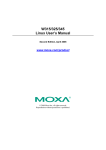
Component Marking Information
The Intel® Xeon® Processor E5 Family can be identified by the following component
markings:
Figure 1.
Production Top-side Markings (Example)
Table 6.
Intel® Xeon® Processor E5-1600 and E5-2600 Product Families Identification
(Sheet 1 of 4)
S-Spec
Number
Stepping
Model
Number
CPUID
Core
Frequency
(GHz)/
DDR3(MHz)/
Intel® QPI
(GHz)
Available bins
of Intel® Turbo
Boost
Technology
TDP
(W)
#
Cores
Cache
Size
(MB)
Notes
SR0HA
C-1
E5-2690
0x206D6
2.9/1600/8.0
4/4/4/5/5/7/7/9
135
8
20
1, 2, 3, 4, 6
SR0GY
C-1
E5-2680
0x206D6
2.7/1600/8.0
4/4/5/5/5/7/8/8
130
8
20
1, 2, 3, 4, 6
SR0H8
C-1
E5-2670
0x206D6
2.6/1600/8.0
4/4/5/5/6/6/7/7
115
8
20
1, 2, 3, 4, 6
SR0H3
C-1
E5-2667
0x206D6
2.9/1600/8.0
3/3/3/4/5/6
130
6
15
1, 2, 3, 4, 6
SR0GZ
C-1
E5-2660
0x206D6
2.2/1600/8.0
5/5/6/6/7/7/8/8
95
8
20
1, 2, 3, 4, 6
SR0H4
C-1
E5-2650
0x206D6
2.0/1600/8.0
4/4/5/5/5/7/8/8
95
8
20
1, 2, 3, 4, 6
SR0H0
C-1
E5-2650L
0x206D6
1.8/1600/8.0
2/2/3/3/4/4/5/5
70
8
20
1, 2, 3, 4, 6
SR0H5
C-1
E5-2640
0x206D6
2.5/1333/7.2
3/3/4/4/5/5
95
6
15
1, 2, 3, 4, 6
SR0H6
C-1
E5-2630
0x206D6
2.3/1333/7.2
3/3/4/4/5/5
95
6
15
1, 2, 3, 4, 6
SR0H1
C-1
E5-2630L
0x206D6
2.0/1333/8.0
3/3/4/4/5/5
60
6
15
1, 2, 3, 4, 6
SR0H7
C-1
E5-2620
0x206D6
2.0/1333/7.2
3/3/4/4/5/5
95
6
15
1, 2, 3, 4, 6
SR0L0
C-2
E5-2690
0x206D7
2.9/1600/8.0
4/4/4/5/5/7/7/9
135
8
20
1, 2, 3, 4
SR0KG
C-2
E5-2687W
0x206D7
3.1/1600/8.0
3/3/3/4/4/5/5/7
150
8
20
1, 2, 3, 4, 5
SR0KH
C-2
E5-2680
0x206D7
2.7/1600/8.0
4/4/5/5/5/7/8/8
130
8
20
1, 2, 3, 4
SR0KX
C-2
E5-2670
0x206D7
2.6/1600/8.0
4/4/5/5/6/6/7/7
115
8
20
1, 2, 3, 4
SR0KP
C-2
E5-2667
0x206D7
2.9/1600/8.0
3/3/3/4/5/6
130
6
15
1, 2, 3, 4
SR0L1
C-2
E5-2665
0x206D7
2.4/1600/8.0
4/4/5/5/6/6/7/7
115
8
20
1, 2, 3, 4
SR0KK
C-2
E5-2660
0x206D7
2.2/1600/8.0
5/5/6/6/7/7/8/8
95
8
20
1, 2, 3, 4
Intel® Xeon® Processor E5 Family
Specification Update, January 2014
21
Table 6.
Intel® Xeon® Processor E5-1600 and E5-2600 Product Families Identification
(Sheet 1 of 4)
S-Spec
Number
Stepping
Model
Number
CPUID
Core
Frequency
(GHz)/
DDR3(MHz)/
Intel® QPI
(GHz)
SR0LZ
C-2
E5-2658
0x206D7
2.1/1600/8.0
0/0/1/1/2/2/3/3
95
8
20
Available bins
of Intel® Turbo
Boost
Technology
TDP
(W)
#
Cores
Cache
Size
(MB)
Notes
1, 2, 3, 4
SR0KQ
C-2
E5-2650
0x206D7
2.0/1600/8.0
4/4/5/5/5/7/8/8
95
8
20
1, 2, 3, 4
SR0KL
C-2
E5-2650L
0x206D7
1.8/1600/8.0
2/2/3/3/4/4/5/5
70
8
20
1, 2, 3, 4
SR0LX
C-2
E5-2648L
0x206D7
1.8/1600/8.0
0/0/1/1/2/2/3/3
70
8
20
1, 2, 3, 4
SR0L7
M-1
E5-2643
0x206D7
3.3/1600/6.4
1/1/2/2
130
4
10
1, 2, 3, 4
SR0KR
C-2
E5-2640
0x206D7
2.5/1333/7.2
3/3/4/4/5/5
95
6
15
1, 2, 3, 4
SR0LE
M-1
E5-2637
0x206D7
3.0/1066/6.4
5/5
80
2
5
1, 2, 3, 4
SR0KV
C-2
E5-2630
0x206D7
2.3/1333/7.2
3/3/4/4/5/5
95
6
15
1, 2, 3, 4
SR0KM
C-2
E5-2630L
0x206D7
2.0/1333/8.0
3/3/4/4/5/5
60
6
15
1, 2, 3, 4
SR0KW
C-2
E5-2620
0x206D7
2.0/1333/7.2
3/3/4/4/5/5
95
6
15
1, 2, 3, 4
SR0LA
M-1
E5-2609
0x206D7
2.4/1066/6.4
N/A
80
4
10
1, 2, 3
SR0LB
M-1
E5-2603
0x206D7
1.8/1066/6.4
N/A
80
4
10
1, 2, 3
SR0KN
C-2
E5-1660
0x206D7
3.3/1600
3/3/4/4/6/6
130
6
15
1, 2, 3, 4, 7
SR0KZ
C-2
E5-1650
0x206D7
3.2/1600
3/3/4/5/6/6
130
6
12
1, 2, 3, 4, 7
SR0LC
M-1
E5-1620
0x206D7
3.6/1600
1/1/2/2
130
4
10
1, 2, 3, 4, 7
Notes:
1.
Intel® Xeon® Processor E5-1600 and E5-2600 Product Families VID codes will change due to temperature and/or current
load changes in order to minimize the power of the part. For specific voltages please refer to the latest Intel® Xeon®
Processor E5-1600/E5-2600/E5-4600 Product Families Datasheet - Volume One, #326508-002.
2.
Please refer to the latest Intel® Xeon® Processor E5-1600/E5-2600/E5-4600 Product Families Datasheet - Volume One,
#326508-002 and Intel® Xeon® Processor E5-1600/E5-2400/E5-2600/E5-4600 Product Families Datasheet - Volume
Two, #326509-003, for information on processor specifications and features.
3.
Please refer to the latest Intel® Xeon® Processor E5-1600/E5-2600/E5-4600 Product Families Datasheet - Volume One,
#326508-002, for information on processor operating temperature and thermal specifications.
4.
This SKU supports Intel® Turbo Boost Technology. Intel® Turbo Boost Technology performance varies depending on
hardware, software and overall system configuration.
5.
The 150W TDP SKU is intended for the dual processor workstations only and uses workstation specific use conditions for
reliability assumptions.
6.
Intel® Trusted Execution Technology (Intel® TXT) is not a supported production feature on the C-1 stepping.
7.
LR-DIMMs are not supported on E5-1600 product family SKUs. All E5-1600 SKUs are workstation only.
Table 7.
Intel® Xeon® Processor E5-4600 Product Family Identification (Sheet 1 of 2)
S-Spec
Number
Stepping
Model
Number
CPUID
Core Frequency
(GHz)/
DDR3(MHz)/
®
Intel QPI (GHz)
Available bins
of Intel® Turbo
Boost
Technology
TDP
(W)
#
Cores
Cach
e
Size
(MB)
Notes
SR0QR
C-2
E5-4650
0x206D7
2.7/1600/8.0
2/2/3/3/3/5/6/6
130
8
20
1, 2, 3, 4, 5
SR0QS
C-2
E5-4650L
0x206D7
2.6/1600/8.0
2/2/3/3/4/4/5/5
115
8
20
1, 2, 3, 4, 5
SR0QT
C-2
E5-4640
0x206D7
2.4/1600/8.0
1/1/2/2/3/3/4/4
95
8
20
1, 2, 3, 4, 5
SR0L4
C-2
E5-4620
0x206D7
2.2/1333/7.2
1/1/2/2/3/3/4/4
95
8
16
1, 2, 3, 4
SR0L5
C-2
E5-4617
0x206D7
2.9/1600/7.2
3/3/4/4/5/5
130
6
15
1, 2, 3, 4, 6
SR0KS
C-2
E5-4610
0x206D7
2.4/1333/7.2
3/3/4/4/5/5
95
6
15
1, 2, 3, 4
SR0KU
C-2
E5-4607
0x206D7
2.2/1066/6.4
N/A
95
6
12
1, 2, 3,
SR0LF
M-1
E5-4603
0x206D7
2.0/1066/6.4
N/A
95
4
10
1, 2, 3,
22
Intel® Xeon® Processor E5 Family
Specification Update, January 2014
Notes:
1.
Intel® Xeon® Processor E5-4600 Product Family VID codes will change due to temperature and/or current load changes
in order to minimize the power of the part. For specific voltages please refer to the latest Intel® Xeon® Processor E51600/E5-2600/E5-4600 Product Families Datasheet - Volume One, #326508-002.
2.
Please refer to the latest Intel® Xeon® Processor E5-1600/E5-2600/E5-4600 Product Families Datasheet - Volume One,
#326508-002 and Intel® Xeon® Processor E5-1600/E5-2400/E5-2600/E5-4600 Product Families External Design
Specification (EDS) - Volume Two, #326509-003 for information on processor specifications and features.
3.
Please refer to the latest Intel® Xeon® Processor E5-1600/E5-2600/E5-4600 Product Families Datasheet - Volume One,
#326508-002, for information on processor operating temperature and thermal specifications.
4.
This SKU supports Intel® Turbo Boost Technology. Intel® Turbo Boost Technology performance varies depending on
hardware, software and overall system configuration.
5.
This SKU includes Machine Check Architecture (MCA) Recovery – Execution Path and Non-Execution Path features.
6.
This SKU does not support Intel® Hyper-Threading Technology.
Intel® Xeon® Processor E5 Family
Specification Update, January 2014
23
Table 8.
Intel® Xeon® Processor E5-2400 Product Family Identification (Sheet 1 of 2)
S-Spec
Number
Stepping
Model
Number
CPUID
Core Frequency
(GHz)/
DDR3(MHz)/
®
Intel QPI (GHz)
Available bins
of Intel® Turbo
Boost
Technology
TDP
(W)
#
Cores
Cache
Size
(MB)
SR0LG
C-2
E5-2470
0x206D7
2.3/1600/8
5/5/6/6/7/7/8/8
95
8
20
1, 2, 3
SR0LJ
C-2
E5-2450
0x206D7
2.1/1600/8
5/5/6/6/7/7/8/8
95
8
20
1, 2, 3
SR0LH
C-2
E5-2450L
0x206D7
1.8/1600/8
2/2/3/3/4/4/5/5
70
8
20
1, 2, 3
SR0M2
C-2
E5-2448L
0x206D7
1.8/1600/8.0
0/0/1/1/2/2/3/3
70
8
20
1, 2, 3
Notes
SR0LK
C-2
E5-2440
0x206D7
2.4/1333/7.2
3/3/4/4/5/5
95
6
15
1, 2, 3
SR0LM
C-2
E5-2430
0x206D7
2.2/1333/7.2
3/3/4/4/5/5
95
6
15
1, 2, 3
SR0LL
C-2
E5-2430L
0x206D7
2.0/1333/7.2
3/3/4/4/5/5
60
6
15
1, 2, 3
SR0M3
C-2
E5-2428L
0x206D7
1.8/1333/7.2
0/0/1/1/2/2
60
6
15
1, 2, 3
SR0LN
C-2
E5-2420
0x206D7
1.9/1333/7.2
3/3/4/4/5/5
95
6
15
1, 2, 3
SR0M5
M-1
E5-2418L
0x206D7
2.0/1333/7.2
0/0/1/1
50
4
10
1, 2, 3
SR0LR
M-1
E5-2407
0x206D7
2.2/1066/6.4
N/A
80
4
10
1, 2, 3
SR0LS
M-1
E5-2403
0x206D7
1.8/1066/6.4
N/A
80
4
10
1, 2, 3
SR0M4
C-2
E5-1428L
0x206D7
1.8/1333
N/A
60
6
15
1, 2, 3
Notes:
1.
Intel® Xeon® Processor E5-2400 Product Family VID codes will change due to temperature and/or current load changes
in order to minimize the power of the part. For specific voltages please refer to the latest Intel® Xeon® E5-2400 Product
Family Datasheet- Volume One, #327248-001.
2.
Please refer to the latest Intel® Xeon® E5-2400 Product Family Datasheet- Volume One, #327248-001 and Intel® Xeon®
Processor E5-1600/E5-2400/E5-2600/E5-4600 Product Families Datasheet - Volume Two, #326509-003, for information
on processor specifications and features.
3.
Please refer to the latest Intel® Xeon® E5-2400 Product Family Datasheet- Volume One, 327248-001, for information on
processor operating temperature and thermal specifications.
24
Intel® Xeon® Processor E5 Family
Specification Update, January 2014
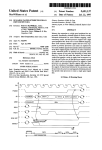
Errata
BT1.
An Enabled Debug Breakpoint or Single Step Trap May Be Taken after
MOV SS/POP SS Instruction if it is Followed by an Instruction That
Signals a Floating Point Exception
Problem:
A MOV SS/POP SS instruction should inhibit all interrupts including debug breakpoints
until after execution of the following instruction. This is intended to allow the sequential
execution of MOV SS/POP SS and MOV [r/e]SP, [r/e]BP instructions without having an
invalid stack during interrupt handling. However, an enabled debug breakpoint or single
step trap may be taken after MOV SS/POP SS if this instruction is followed by an
instruction that signals a floating point exception rather than a MOV [r/e]SP, [r/e]BP
instruction. This results in a debug exception being signaled on an unexpected
instruction boundary since the MOV SS/POP SS and the following instruction should be
executed atomically.
Implication:
This can result in incorrect signaling of a debug exception and possibly a mismatched
Stack Segment and Stack Pointer. If MOV SS/POP SS is not followed by a MOV [r/e]SP,
[r/e]BP, there may be a mismatched Stack Segment and Stack Pointer on any
exception. Intel has not observed this erratum with any commercially available
software or system.
Workaround: As recommended in the IA32 Intel® Architecture Software Developer’s Manual, the use
of MOV SS/POP SS in conjunction with MOV [r/e]SP, [r/e]BP will avoid the failure since
the MOV [r/e]SP, [r/e]BP will not generate a floating point exception. Developers of
debug tools should be aware of the potential incorrect debug event signaling created by
this erratum.
Status:
For the affected steppings, see the Summary Tables of Changes.
BT2.
APIC Error “Received Illegal Vector” May be Lost
Problem:
APIC (Advanced Programmable Interrupt Controller) may not update the ESR (Error
Status Register) flag Received Illegal Vector bit [6] properly when an illegal vector error
is received on the same internal clock that the ESR is being written (as part of the
write-read ESR access flow). The corresponding error interrupt will also not be
generated for this case.
Implication:
Due to this erratum, an incoming illegal vector error may not be logged into ESR
properly and may not generate an error interrupt.
Workaround: None identified.
Status:
For the affected steppings, see the Summary Tables of Changes.
BT3.
An Uncorrectable Error Logged in IA32_CR_MC2_STATUS May also
Result in a System Hang
Problem:
Uncorrectable errors logged in IA32_CR_MC2_STATUS MSR (409H) may also result in a
system hang causing an Internal Timer Error (MCACOD = 0x0400h) to be logged in
another machine check bank (IA32_MCi_STATUS).
Implication:
Uncorrectable errors logged in IA32_CR_MC2_STATUS can further cause a system hang
and an Internal Timer Error to be logged.
Workaround: None identified.
Status:
For the affected steppings, see the Summary Tables of Changes.
BT4.
B0-B3 Bits in DR6 For Non-Enabled Breakpoints May be Incorrectly Set
Problem:
Some of the B0-B3 bits (breakpoint conditions detect flags, bits [3:0]) in DR6 may be
incorrectly set for non-enabled breakpoints when the following sequence happens:
1. MOV or POP instruction to SS (Stack Segment) selector;
Intel® Xeon® Processor E5 Family
Specification Update, January 2014
25
2. Next instruction is FP (Floating Point) that gets FP assist
3. Another instruction after the FP instruction completes successfully
4. A breakpoint occurs due to either a data breakpoint on the preceding instruction or
a code breakpoint on the next instruction.
Due to this erratum a non-enabled breakpoint triggered on step 1 or step 2 may be
reported in B0-B3 after the breakpoint occurs in step 4.
Implication:
Due to this erratum, B0-B3 bits in DR6 may be incorrectly set for non-enabled
breakpoints.
Workaround: Software should not execute a floating point instruction directly after a MOV SS or POP
SS instruction.
Status:
For the affected steppings, see the Summary Tables of Changes.
BT5.
Changing the Memory Type for an In-Use Page Translation May Lead
to Memory-Ordering Violations
Problem:
Under complex microarchitectural conditions, if software changes the memory type for
data being actively used and shared by multiple threads without the use of semaphores
or barriers, software may see load operations execute out of order.
Implication:
Memory ordering may be violated. Intel has not observed this erratum with any
commercially available software.
Workaround: Software should ensure pages are not being actively used before requesting their
memory type be changed.
Status:
For the affected steppings, see the Summary Tables of Changes.
BT6.
Code Segment Limit/Canonical Faults on RSM May be Serviced before
Higher Priority Interrupts/Exceptions and May Push the Wrong
Address Onto the Stack
Problem:
Normally, when the processor encounters a Segment Limit or Canonical Fault due to
code execution, a #GP (General Protection Exception) fault is generated after all higher
priority Interrupts and exceptions are serviced. Due to this erratum, if RSM (Resume
from System Management Mode) returns to execution flow that results in a Code
Segment Limit or Canonical Fault, the #GP fault may be serviced before a higher
priority Interrupt or Exception (for example, NMI (Non-Maskable Interrupt), Debug
break(#DB), Machine Check (#MC), and so forth). If the RSM attempts to return to a
non-canonical address, the address pushed onto the stack for this #GP fault may not
match the non-canonical address that caused the fault.
Implication:
Operating systems may observe a #GP fault being serviced before higher priority
Interrupts and Exceptions. Intel has not observed this erratum on any commercially
available software.
Workaround: None identified.
Status:
For the affected steppings, see the Summary Tables of Changes.
BT7.
Corruption of CS Segment Register During RSM While Transitioning
From Real Mode to Protected Mode
Problem:
During the transition from real mode to protected mode, if an SMI (System
Management Interrupt) occurs between the MOV to CR0 that sets PE (Protection
Enable, bit 0) and the first far JMP, the subsequent RSM (Resume from System
Management Mode) may cause the lower two bits of CS segment register to be
corrupted.
Implication:
The corruption of the bottom two bits of the CS segment register will have no impact
unless software explicitly examines the CS segment register between enabling
protected mode and the first far JMP. Intel® 64 and IA-32 Architectures Software
Developer’s Manual Volume 3A: System Programming Guide, Part 1, in the section
26
Intel® Xeon® Processor E5 Family
Specification Update, January 2014
titled “Switching to Protected Mode” recommends the far JMP immediately follows the
write to CR0 to enable protected mode. Intel has not observed this erratum with any
commercially available software.
Workaround: None identified.
Status:
For the affected steppings, see the Summary Tables of Changes.
BT8.
Debug Exception Flags DR6.B0-B3 Flags May be Incorrect for Disabled
Breakpoints
Problem:
When a debug exception is signaled on a load that crosses cache lines with data
forwarded from a store and whose corresponding breakpoint enable flags are disabled
(DR7.G0-G3 and DR7.L0-L3), the DR6.B0-B3 flags may be incorrect.
Implication:
The debug exception DR6.B0-B3 flags may be incorrect for the load if the
corresponding breakpoint enable flag in DR7 is disabled.
Workaround: None identified.
Status:
For the affected steppings, see the Summary Tables of Changes.
BT9.
DR6 May Contain Incorrect Information When the First Instruction
After a MOV SS,r/m or POP SS is a Store
Problem:
Normally, each instruction clears the changes in DR6 (Debug Status Register) caused
by the previous instruction. However, the instruction following a MOV SS,r/m (MOV to
the stack segment selector) or POP SS (POP stack segment selector) instruction will not
clear the changes in DR6 because data breakpoints are not taken immediately after a
MOV SS,r/m or POP SS instruction. Due to this erratum, any DR6 changes caused by a
MOV SS,r/m or POP SS instruction may be cleared if the following instruction is a store.
Implication:
When this erratum occurs, incorrect information may exist in DR6. This erratum will not
be observed under normal usage of the MOV SS,r/m or POP SS instructions (that is,
following them with an instruction that writes [e/r]SP). When debugging or when
developing debuggers, this behavior should be noted.
Workaround: None identified.
Status:
For the affected steppings, see the Summary Tables of Changes.
BT10.
EFLAGS Discrepancy on Page Faults and on EPT-Induced VM Exits
after a Translation Change
Problem:
This erratum is regarding the case where paging structures are modified to change a
linear address from writable to non-writable without software performing an
appropriate TLB invalidation. When a subsequent access to that address by a specific
instruction (ADD, AND, BTC, BTR, BTS, CMPXCHG, DEC, INC, NEG, NOT, OR, ROL/ROR,
SAL/SAR/SHL/SHR, SHLD, SHRD, SUB, XOR, and XADD) causes a page fault or an EPTinduced VM exit, the value saved for EFLAGS may incorrectly contain the arithmetic flag
values that the EFLAGS register would have held had the instruction completed without
fault or VM exit. For page faults, this can occur even if the fault causes a VM exit or if
its delivery causes a nested fault.
Implication:
None identified. Although the EFLAGS value saved by an affected event (a page fault or
an EPT-induced VM exit) may contain incorrect arithmetic flag values, Intel has not
identified software that is affected by this erratum. This erratum will have no further
effects once the original instruction is restarted because the instruction will produce the
same results as if it had initially completed without fault or VM exit.
Workaround: If the handler of the affected events inspects the arithmetic portion of the saved
EFLAGS value, then system software should perform a synchronized paging structure
modification and TLB invalidation.
Status:
For the affected steppings, see the Summary Tables of Changes.
Intel® Xeon® Processor E5 Family
Specification Update, January 2014
27
BT11.
Fault on ENTER Instruction May Result in Unexpected Values on Stack
Frame
Problem:
The ENTER instruction is used to create a procedure stack frame. Due to this erratum,
if execution of the ENTER instruction results in a fault, the dynamic storage area of the
resultant stack frame may contain unexpected values (that is, residual stack data as a
result of processing the fault).
Implication:
Data in the created stack frame may be altered following a fault on the ENTER
instruction. Please refer to “Procedure Calls For Block-Structured Languages” in IA-32
Intel® Architecture Software Developer’s Manual, Vol. 1, Basic Architecture, for
information on the usage of the ENTER instructions. This erratum is not expected to
occur in ring 3. Faults are usually processed in ring 0 and stack switch occurs when
transferring to ring 0. Intel has not observed this erratum on any commercially
available software.
Workaround: None identified.
Status:
For the affected steppings, see the Summary Tables of Changes.
BT12.
Faulting MMX Instruction May Incorrectly Update x87 FPU Tag Word
Problem:
Under a specific set of conditions, MMX stores (MOVD, MOVQ, MOVNTQ, MASKMOVQ)
which cause memory access faults (#GP, #SS, #PF, or #AC), may incorrectly update
the x87 FPU tag word register.
This erratum will occur when the following additional conditions are also met.
• The MMX store instruction must be the first MMX instruction to operate on x87 FPU
state (that is, the x87 FP tag word is not already set to 0x0000).
• For MOVD, MOVQ, MOVNTQ stores, the instruction must use an addressing mode
that uses an index register (this condition does not apply to MASKMOVQ).
Implication:
If the erratum conditions are met, the x87 FPU tag word register may be incorrectly set
to a 0x0000 value when it should not have been modified.
Workaround: None identified.
Status:
For the affected steppings, see the Summary Tables of Changes.
BT13.
FREEZE_WHILE_SMM Does Not Prevent Event From Pending PEBS
During SMM
Problem:
In general, a PEBS record should be generated on the first count of the event after the
counter has overflowed. However, IA32_DEBUGCTL_MSR.FREEZE_WHILE_SMM (MSR
1D9H, bit [14]) prevents performance counters from counting during SMM (System
Management Mode). Due to this erratum, if:
1. A performance counter overflowed before an SMI
2. A PEBS record has not yet been generated because another count of the event has
not occurred
3. The monitored event occurs during SMM
then a PEBS record will be saved after the next RSM instruction.
When FREEZE_WHILE_SMM is set, a PEBS should not be generated until the event
occurs outside of SMM.
Implication:
A PEBS record may be saved after an RSM instruction due to the associated
performance counter detecting the monitored event during SMM; even when
FREEZE_WHILE_SMM is set.
Workaround: None identified.
Status:
28
For the affected steppings, see the Summary Tables of Changes.
Intel® Xeon® Processor E5 Family
Specification Update, January 2014
BT14.
General Protection Fault (#GP) for Instructions Greater than 15 Bytes
May be Preempted
Problem:
When the processor encounters an instruction that is greater than 15 bytes in length, a
#GP is signaled when the instruction is decoded. Under some circumstances, the #GP
fault may be preempted by another lower priority fault (for example, Page Fault (#PF)).
However, if the preempting lower priority faults are resolved by the operating system
and the instruction retried, a #GP fault will occur.
Implication:
Software may observe a lower-priority fault occurring before or in lieu of a #GP fault.
Instructions of greater than 15 bytes in length can only occur if redundant prefixes are
placed before the instruction.
Workaround: None identified.
Status:
For the affected steppings, see the Summary Tables of Changes.
BT15.
#GP on Segment Selector Descriptor that Straddles Canonical
Boundary May Not Provide Correct Exception Error Code
Problem:
During a #GP (General Protection Exception), the processor pushes an error code on to
the exception handler’s stack. If the segment selector descriptor straddles the
canonical boundary, the error code pushed onto the stack may be incorrect.
Implication:
An incorrect error code may be pushed onto the stack. Intel has not observed this
erratum with any commercially available software.
Workaround: None identified.
Status:
For the affected steppings, see the Summary Tables of Changes.
BT16.
IO_SMI Indication in SMRAM State Save Area May be Set Incorrectly
Problem:
The IO_SMI bit in SMRAM’s location 7FA4H is set to “1” by the CPU to indicate a System
Management Interrupt (SMI) occurred as the result of executing an instruction that
reads from an I/O port. Due to this erratum, the IO_SMI bit may be incorrectly set by:
• A non-I/O instruction
• SMI is pending while a lower priority event interrupts
• A REP I/O read
• A I/O read that redirects to MWAIT
Implication:
SMM handlers may get false IO_SMI indication.
Workaround: The SMM handler has to evaluate the saved context to determine if the SMI was
triggered by an instruction that read from an I/O port. The SMM handler must not
restart an I/O instruction if the platform has not been configured to generate a
synchronous SMI for the recorded I/O port address.
Status:
For the affected steppings, see the Summary Tables of Changes.
BT17.
IRET under Certain Conditions May Cause an Unexpected Alignment
Check Exception
Problem:
In IA-32e mode, it is possible to get an Alignment Check Exception (#AC) on the IRET
instruction even though alignment checks were disabled at the start of the IRET. This
can only occur if the IRET instruction is returning from CPL3 code to CPL3 code. IRETs
from CPL0/1/2 are not affected. This erratum can occur if the EFLAGS value on the
stack has the AC flag set, and the interrupt handler's stack is misaligned. In IA-32e
mode, RSP is aligned to a 16-byte boundary before pushing the stack frame.
Implication:
In IA-32e mode, under the conditions given above, an IRET can get a #AC even if
alignment checks are disabled at the start of the IRET. This erratum can only be
observed with a software generated stack frame.
Workaround: Software should not generate misaligned stack frames for use with IRET.
Status:
For the affected steppings, see the Summary Tables of Changes.
Intel® Xeon® Processor E5 Family
Specification Update, January 2014
29
BT18.
LER MSRs May Be Unreliable
Problem:
Due to certain internal processor events, updates to the LER (Last Exception Record)
MSRs, MSR_LER_FROM_LIP (1DDH) and MSR_LER_TO_LIP (1DEH), may happen when
no update was expected.
Implication:
The values of the LER MSRs may be unreliable.
Workaround: None Identified.
Status:
For the affected steppings, see the Summary Tables of Changes.
BT19.
LBR, BTS, BTM May Report a Wrong Address when an Exception/
Interrupt Occurs in 64-bit Mode
Problem:
An exception/interrupt event should be transparent to the LBR (Last Branch Record),
BTS (Branch Trace Store) and BTM (Branch Trace Message) mechanisms. However,
during a specific boundary condition where the exception/interrupt occurs right after
the execution of an instruction at the lower canonical boundary (0x00007FFFFFFFFFFF)
in 64-bit mode, the LBR return registers will save a wrong return address with bits 63
to 48 incorrectly sign extended to all 1’s. Subsequent BTS and BTM operations which
report the LBR will also be incorrect.
Implication:
LBR, BTS and BTM may report incorrect information in the event of an exception/
interrupt.
Workaround:
None identified.
Status:
For the affected steppings, see the Summary Tables of Changes.
BT20.
MCi_Status Overflow Bit May Be Incorrectly Set on a Single Instance
of a DTLB Error
Problem:
A single Data Translation Look Aside Buffer (DTLB) error can incorrectly set the
Overflow (bit [62]) in the MCi_Status register. A DTLB error is indicated by MCA error
code (bits [15:0]) appearing as binary value, 000x 0000 0001 0100, in the MCi_Status
register.
Implication:
Due to this erratum, the Overflow bit in the MCi_Status register may not be an accurate
indication of multiple occurrences of DTLB errors. There is no other impact to normal
processor functionality.
Workaround: None identified.
Status:
For the affected steppings, see the Summary Tables of Changes.
BT21.
MONITOR or CLFLUSH on the Local XAPIC's Address Space Results in
Hang
Problem:
If the target linear address range for a MONITOR or CLFLUSH is mapped to the local
xAPIC's address space, the processor will hang.
Implication:
When this erratum occurs, the processor will hang. The local xAPIC's address space
must be uncached. The MONITOR instruction only functions correctly if the specified
linear address range is of the type write-back. CLFLUSH flushes data from the cache.
Intel has not observed this erratum with any commercially available software.
Workaround: Do not execute MONITOR or CLFLUSH instructions on the local xAPIC address space.
Status:
For the affected steppings, see the Summary Tables of Changes.
BT22.
MOV To/From Debug Registers Causes Debug Exception
Problem:
When in V86 mode, if a MOV instruction is executed to/from a debug registers, a
general-protection exception (#GP) should be generated. However, in the case when
the general detect enable flag (GD) bit is set, the observed behavior is that a debug
exception (#DB) is generated instead.
30
Intel® Xeon® Processor E5 Family
Specification Update, January 2014
Implication:
With debug-register protection enabled (that is, the GD bit set), when attempting to
execute a MOV on debug registers in V86 mode, a debug exception will be generated
instead of the expected general-protection fault.
Workaround: In general, operating systems do not set the GD bit when they are in V86 mode. The
GD bit is generally set and used by debuggers. The debug exception handler should
check that the exception did not occur in V86 mode before continuing. If the exception
did occur in V86 mode, the exception may be directed to the general-protection
exception handler.
Status:
For the affected steppings, see the Summary Tables of Changes.
BT23.
PEBS Record not Updated when in Probe Mode
Problem:
When a performance monitoring counter is configured for PEBS (Precise Event Based
Sampling), overflows of the counter can result in storage of a PEBS record in the PEBS
buffer. Due to this erratum, if the overflow occurs during probe mode, it may be
ignored and a new PEBS record may not be added to the PEBS buffer.
Implication:
Due to this erratum, the PEBS buffer may not be updated by overflows that occur
during probe mode.
Workaround: None identified.
Status:
For the affected steppings, see the Summary Tables of Changes.
BT24.
Performance Monitor Counter INST_RETIRED.STORES May Count
Higher than Expected
Problem:
Performance Monitoring counter INST_RETIRED.STORES (Event: C0H) is used to track
retired instructions which contain a store operation. Due to this erratum, the processor
may also count other types of instructions including WRMSR and MFENCE.
Implication:
Performance Monitoring counter INST_RETIRED.STORES may report counts higher than
expected.
Workaround: None identified.
Status:
For the affected steppings, see the Summary Tables of Changes.
BT25.
Performance Monitoring Event FP_MMX_TRANS_TO_MMX May Not
Count Some Transitions
Problem:
Performance Monitor Event FP_MMX_TRANS_TO_MMX (Event CCH, Umask 01H) counts
transitions from x87 Floating Point (FP) to MMX™ instructions. Due to this erratum, if
only a small number of MMX instructions (including EMMS) are executed immediately
after the last FP instruction, a FP to MMX transition may not be counted.
Implication:
The count value for Performance Monitoring Event FP_MMX_TRANS_TO_MMX may be
lower than expected. The degree of undercounting is dependent on the occurrences of
the erratum condition while the counter is active. Intel has not observed this erratum
with any commercially available software.
Workaround: None Identified.
Status:
For the affected steppings, see the Summary Tables of Changes.
BT26.
REP MOVS/STOS Executing with Fast Strings Enabled and Crossing
Page Boundaries with Inconsistent Memory Types may use an
Incorrect Data Size or Lead to Memory-Ordering Violations.
Problem:
Under certain conditions as described in the Software Developers Manual section “Outof-Order Stores For String Operations in Pentium® 4, Intel® Xeon®, and P6 Family
Processors” the processor performs REP MOVS or REP STOS as fast strings. Due to this
erratum fast string REP MOVS/REP STOS instructions that cross page boundaries from
WB/WC memory types to UC/WP/WT memory types, may start using an incorrect data
size or may observe memory ordering violations.
Intel® Xeon® Processor E5 Family
Specification Update, January 2014
31
Implication:
Upon crossing the page boundary the following may occur, dependent on the new page
memory type:
• UC the data size of each write will now always be 8 bytes, as opposed to the
original data size.
• WP the data size of each write will now always be 8 bytes, as opposed to the
original data size and there may be a memory ordering violation.
• WT there may be a memory ordering violation.
Workaround: Software should avoid crossing page boundaries from WB or WC memory type to UC,
WP or WT memory type within a single REP MOVS or REP STOS instruction that will
execute with fast strings enabled.
Status:
For the affected steppings, see the Summary Tables of Changes.
BT27.
Reported Memory Type May Not Be Used to Access the VMCS and
Referenced Data Structures
Problem:
Bits 53:50 of the IA32_VMX_BASIC MSR report the memory type that the processor
uses to access the VMCS and data structures referenced by pointers in the VMCS. Due
to this erratum, a VMX access to the VMCS or referenced data structures will instead
use the memory type that the MTRRs (memory-type range registers) specify for the
physical address of the access.
Implication:
Bits 53:50 of the IA32_VMX_BASIC MSR report that the WB (write-back) memory type
will be used but the processor may use a different memory type.
Workaround: Software should ensure that the VMCS and referenced data structures are located at
physical addresses that are mapped to WB memory type by the MTRRs.
Status:
For the affected steppings, see the Summary Tables of Changes.
BT28.
Single Step Interrupts with Floating Point Exception Pending May Be
Mishandled
Problem:
In certain circumstances, when a floating point exception (#MF) is pending during
single-step execution, processing of the single-step debug exception (#DB) may be
mishandled.
Implication:
When this erratum occurs, #DB will be incorrectly handled as follows:
• #DB is signaled before the pending higher priority #MF (Interrupt 16)
• #DB is generated twice on the same instruction
Workaround: None identified.
Status:
For the affected steppings, see the Summary Tables of Changes.
BT29.
Storage of PEBS Record Delayed Following Execution of MOV SS or STI
Problem:
When a performance monitoring counter is configured for PEBS (Precise Event Based
Sampling), overflow of the counter results in storage of a PEBS record in the PEBS
buffer. The information in the PEBS record represents the state of the next instruction
to be executed following the counter overflow. Due to this erratum, if the counter
overflow occurs after execution of either MOV SS or STI, storage of the PEBS record is
delayed by one instruction.
Implication:
When this erratum occurs, software may observe storage of the PEBS record being
delayed by one instruction following execution of MOV SS or STI. The state information
in the PEBS record will also reflect the one instruction delay.
Workaround: None identified.
Status:
32
For the affected steppings, see the Summary Tables of Changes.
Intel® Xeon® Processor E5 Family
Specification Update, January 2014
BT30.
The Processor May Report a #TS Instead of a #GP Fault
Problem:
A jump to a busy TSS (Task-State Segment) may cause a #TS (invalid TSS exception)
instead of a #GP fault (general protection exception).
Implication:
Operation systems that access a busy TSS may get invalid TSS fault instead of a #GP
fault. Intel has not observed this erratum with any commercially available software.
Workaround: None identified.
Status:
For the affected steppings, see the Summary Tables of Changes.
BT31.
VM Exits Due to “NMI-Window Exiting” May Be Delayed by One
Instruction
Problem:
If VM entry is executed with the “NMI-window exiting” VM-execution control set to 1, a
VM exit with exit reason “NMI window” should occur before execution of any instruction
if there is no virtual-NMI blocking, no blocking of events by MOV SS, and no blocking of
events by STI. If VM entry is made with no virtual-NMI blocking but with blocking of
events by either MOV SS or STI, such a VM exit should occur after execution of one
instruction in VMX non-root operation. Due to this erratum, the VM exit may be delayed
by one additional instruction.
Implication:
VMM software using “NMI-window exiting” for NMI virtualization should generally be
unaffected, as the erratum causes at most a one-instruction delay in the injection of a
virtual NMI, which is virtually asynchronous. The erratum may affect VMMs relying on
deterministic delivery of the affected VM exits.
Workaround: None identified.
Status:
For the affected steppings, see the Summary Tables of Changes.
BT32.
Values for LBR/BTS/BTM Will be Incorrect after an Exit from SMM
Problem:
After a return from SMM (System Management Mode), the CPU will incorrectly update
the LBR (Last Branch Record) and the BTS (Branch Trace Store), hence rendering their
data invalid. The corresponding data if sent out as a BTM on the system bus will also be
incorrect.
Note:
This issue would only occur when one of the 3 above mentioned debug support facilities
are used.
Implication:
The value of the LBR, BTS, and BTM immediately after an RSM operation should not be
used.
Workaround: None identified.
Status:
For the affected steppings, see the Summary Tables of Changes.
BT33.
VPHMINPOSUW Instruction in VEX Format Does Not Signal #UD
(Invalid Opcode Exception) When vex.vvvv !=1111
Problem:
Processor does not signal #UD fault when executing the reserved instruction
VPHMINPOSUW with vex.vvvv!=1111. The VPHMINPOSUW instruction is described in
greater detail in the Intel® Advanced Vector Extensions Programming Reference.
Implication:
Executing VPHMINPOSUW with vex.vvvv != 1111 results in same behavior as
vex.vvvv= 1111.
Workaround: SW should not use VPHMINPOSUW with vex.vvvv != 1111 in order to ensure future
compatibility.
Status:
For the affected steppings, see the Summary Tables of Changes.
BT34.
Pending x87 FPU Exceptions (#MF) May be Signaled Earlier Than
Expected
Problem:
x87 instructions that trigger #MF normally service interrupts before the #MF. Due to
this erratum, if an instruction that triggers #MF is executed while Enhanced Intel
Intel® Xeon® Processor E5 Family
Specification Update, January 2014
33
SpeedStep® Technology transitions, Intel® Turbo Boost Technology transitions, or
Thermal Monitor events occur, the pending #MF may be signaled before pending
interrupts are serviced.
Implication:
Software may observe #MF being signaled before pending interrupts are serviced.
Workaround: None identified.
Status:
For the affected steppings, see the Summary Tables of Changes.
BT35.
VMREAD/VMWRITE Instruction May Not Fail When Accessing an
Unsupported Field in VMCS
Problem:
The Intel® 64 and IA-32 Architectures Software Developer’s Manual, Volume 2B states
that execution of VMREAD or VMWRITE should fail if the value of the instruction’s
register source operand corresponds to an unsupported field in the VMCS (Virtual
Machine Control Structure). The correct operation is that the logical processor will set
the ZF (Zero Flag), write 0CH into the VM-instruction error field and for VMREAD leave
the instruction’s destination operand unmodified. Due to this erratum, the instruction
may instead clear the ZF, leave the VM-instruction error field unmodified and for
VMREAD modify the contents of its destination operand.
Implication:
Accessing an unsupported field in VMCS will fail to properly report an error. In addition,
VMREAD from an unsupported VMCS field may unexpectedly change its destination
operand. Intel has not observed this erratum with any commercially available software.
Workaround: Software should avoid accessing unsupported fields in a VMCS.
Status:
For the affected steppings, see the Summary Tables of Changes.
BT36.
Unexpected #UD on VZEROALL/VZEROUPPER
Problem:
Execution of the VZEROALL or VZEROUPPER instructions in 64-bit mode with VEX.W set
to 1 may erroneously cause a #UD (invalid-opcode exception).
Implication:
The affected instructions may produce unexpected invalid-opcode exceptions in 64-bit
mode.
Workaround: Compilers should encode VEX.W = 0 for the VZEROALL and VZEROUPPER instructions.
Status:
For the affected steppings, see the Summary Tables of Changes.
BT37.
Execution of Opcode 9BH with the VEX Opcode Extension May Produce
a #NM Exception
Problem:
Attempt to use opcode 9BH with a VEX opcode extension should produce a #UD
(Invalid-Opcode) exception. Due to this erratum, if CR0.MP and CR0.TS are both 1, the
processor may produce a #NM (Device-Not-Available) exception if one of the following
conditions exists:
• 66H, F2H, F3H or REX as a preceding prefix;
• An illegal map specified in the VEX.mmmmm field;
Implication:
Due to this erratum, some undefined instruction encodings may produce a #NM instead
of a #UD exception.
Workaround: Software should not use opcode 9BH with the VEX opcode extension.
Status:
For the affected steppings, see the Summary Tables of Changes.
BT38.
Erratum Removed
BT39.
An Unexpected Page Fault or EPT Violation May Occur After Another
Logical Processor Creates a Valid Translation for a Page
Problem:
An unexpected page fault (#PF) or EPT violation may occur for a page under the
following conditions:
• The paging structures initially specify no valid translation for the page.
34
Intel® Xeon® Processor E5 Family
Specification Update, January 2014
• Software on one logical processor modifies the paging structures so that there is a
valid translation for the page (for example, by setting to 1 the present bit in one of
the paging-structure entries used to translate the page).
• Software on another logical processor observes this modification (for example, by
accessing a linear address on the page or by reading the modified paging-structure
entry and seeing value 1 for the present bit).
• Shortly thereafter, software on that other logical processor performs a store to a
linear address on the page.
In this case, the store may cause a page fault or EPT violation that indicates that there
is no translation for the page (for example, with bit 0 clear in the page-fault error code,
indicating that the fault was caused by a not-present page). Intel has not observed this
erratum with any commercially available software.
Implication:
An unexpected page fault may be reported. There are no other side effects due to this
erratum.
Workaround: System software can be constructed to tolerate these unexpected page faults. See
Section “Propagation of Paging-Structure Changes to Multiple Processors” of Volume 3A
of IA-32 Intel® Architecture Software Developer’s Manual, for recommendations for
software treatment of asynchronous paging-structure updates.
Status:
For the affected steppings, see the Summary Tables of Changes.
BT40.
Execution of FXSAVE or FXRSTOR With the VEX Prefix May Produce a
#NM Exception
Problem:
Attempt to use FXSAVE or FXRSTOR with a VEX prefix should produce a #UD (InvalidOpcode) exception. If either the TS or EM flag bits in CR0 are set, a #NM (device-notavailable) exception will be raised instead of #UD exception.
Implication:
Due to this erratum a #NM exception may be signaled instead of a #UD exception on
an FXSAVE or an FXRSTOR with a VEX prefix.
Workaround: Software should not use FXSAVE or FXRSTOR with the VEX prefix.
Status:
For the affected steppings, see the Summary Tables of Changes.
BT41.
Unexpected #UD on VPEXTRD/VPINSRD
Problem:
Execution of the VPEXTRD or VPINSRD instructions outside of 64-bit mode with VEX.W
set to 1 may erroneously cause a #UD (invalid-opcode exception).
Implication:
The affected instructions may produce unexpected invalid-opcode exceptions outside
64-bit mode.
Workaround: Software should encode VEX.W = 0 for executions of the VPEXTRD and VPINSRD
instructions outside 64-bit mode.
Status:
For the affected steppings, see the Summary Tables of Changes.
BT42.
#GP May be Signaled When Invalid VEX Prefix Precedes Conditional
Branch Instructions
Problem:
When a 2-byte opcode of a conditional branch (opcodes 0F8xH, for any value of x)
instruction resides in 16-bit code-segment and is associated with invalid VEX prefix, it
may sometimes signal a #GP fault (illegal instruction length > 15-bytes) instead of a
#UD (illegal opcode) fault.
Implication:
Due to this erratum, #GP fault instead of a #UD may be signaled on an illegal
instruction.
Workaround: None identified.
Status:
For the affected steppings, see the Summary Tables of Changes.
Intel® Xeon® Processor E5 Family
Specification Update, January 2014
35
BT43.
LBR, BTM or BTS Records May have Incorrect Branch From
Information After an Enhanced Intel® SpeedStep Technology/Tstate/S-state/C1E Transition or Adaptive Thermal Throttling
Problem:
The “From” address associated with the LBR (Last Branch Record), BTM (Branch Trace
Message) or BTS (Branch Trace Store) may be incorrect for the first branch after a
transition of:
• Enhanced Intel SpeedStep® Technology
• T-state (Thermal Monitor states)
• S1-state (ACPI package sleep state)
• C1E (Enhanced C1 Low Power state)
• Adaptive Thermal Throttling
Implication:
When the LBRs, BTM or BTS are enabled, some records may have incorrect branch
“From” addresses for the first branch after a transition of Enhanced Intel SpeedStep®
Technology, T-states, S-states, C1E, or Adaptive Thermal Throttling.
Workaround: None identified.
Status:
For the affected steppings, see the Summary Tables of Changes.
BT44.
A Write to the IA32_FIXED_CTR1 MSR May Result in Incorrect Value in
Certain Conditions
Problem:
Under specific internal conditions, if software tries to write the IA32_FIXED_CTR1 MSR
(30AH) a value that has all bits [31:1] set while the counter was just about to overflow
when the write is attempted (that is, its value was 0xFFFF FFFF FFFF), then due to this
erratum the new value in the MSR may be corrupted.
Implication:
Due to this erratum, IA32_FIXED_CTR1 MSR may be written with a corrupted value.
Workaround: Software may avoid this erratum by writing zeros to the IA32_FIXED_CTR1 MSR,
before the desired write operation.
Status:
For the affected steppings, see the Summary Tables of Changes.
BT45.
Instruction Fetch May Cause Machine Check if Page Size and Memory
Type Was Changed Without Invalidation
Problem:
This erratum may cause a machine check error (IA32_MCi_STATUS.MCACOD=0150H)
on the fetch of an instruction that crosses a 4-KByte address boundary. It applies only
if (1) the 4-KByte linear region on which the instruction begins is originally translated
using a 4-KByte page with the WB memory type; (2) the paging structures are later
modified so that linear region is translated using a large page (2-MByte, 4-MByte, or 1GByte) with the UC memory type; and (3) the instruction fetch occurs after the pagingstructure modification but before software invalidates any TLB entries for the linear
region.
Implication:
Due to this erratum an unexpected machine check with error code 0150H may occur,
possibly resulting in a shutdown. Intel has not observed this erratum with any
commercially available software.
Workaround: Software should not write to a paging-structure entry in a way that would change, for
any linear address, both the page size and the memory type. It can instead use the
following algorithm: first clear the P flag in the relevant paging-structure entry (for
example, PDE); then invalidate any translations for the affected linear addresses; and
then modify the relevant paging-structure entry to set the P flag and establish the new
page size and memory type.
Status:
36
For the affected steppings, see the Summary Tables of Changes.
Intel® Xeon® Processor E5 Family
Specification Update, January 2014
BT46.
L1 Data Cache Errors May be Logged With Level Set to 1 Instead of 0
Problem:
When an L1 Data Cache error is logged in IA32_MCi_STATUS[15:0], which is the MCA
Error Code Field, with a cache error type of the format 0000 0001 RRRR TTLL, the LL
field may be incorrectly encoded as 01b instead of 00b.
Implication:
An error in the L1 Data Cache may report the same LL value as the L2 Cache. Software
should not assume that an LL value of 01b is the L2 Cache.
Workaround: None identified.
Status:
For the affected steppings, see the Summary Tables of Changes.
BT47.
Warm Reset May Leave the System in an Invalid Poisoning State and
Could Cause The Feature to be Disabled
Problem:
Due to this erratum, the PCIe Poison forwarding enable and Intel® QuickPath
Interconnect (Intel® QPI) Poison Enable bits are cleared by warm reset, but other bits
related to the Poisoning feature remain set. After the warm reset the system may be in
an invalid state in regards to the Poisoning bits. This invalid state may cause the
feature to be disabled.
Implication:
This invalid state may prevent the propagation of the poisoning indication, effectively
disabling the feature.
Workaround: If poisoning is disabled, program the following bits to 0 after reset. If poisoning is
enabled, program the following bits to 1 after reset:
The IA32_MCG_CONTAIN.POISON_ENABLE bit (MSR 178H, bit 0). It should be noted
that each thread must perform this action.
The IA32_MCG_CONTAIN.POISON_ENABLE (MSR 178H, bit 0).
The POISFEN bit (IIOMISCCTRL; CPUBUS(0); Device 5; Function 0; Offset 1C0H; Bit
37).
The DMASK bit (UNCEDMASK; CPUBUS(0); Device 0, 1, 2, 3; Functions 0, 1, 2, 3;
Offset 218H; bit 12).
Status:
For the affected steppings, see the Summary Tables of Changes.
BT48.
VM Entries That Return From SMM Using VMLAUNCH May Not Update
The Launch State of the VMCS
Problem:
Successful VM entries using the VMLAUNCH instruction should set the launch state of
the VMCS to “launched”. Due to this erratum, such a VM entry may not update the
launch state of the current VMCS if the VM entry is returning from SMM.
Implication:
Subsequent VM entries using the VMRESUME instruction with this VMCS will fail.
RFLAGS.ZF is set to 1 and the value 5 (indicating VMRESUME with non-launched VMCS)
is stored in the VM-instruction error field. This erratum applies only if dual monitor
treatment of SMI and SMM is active.
Workaround: It is possible for the BIOS to contain a workaround for this erratum.
Status:
For the affected steppings, see the Summary Tables of Changes.
BT49.
Interrupt From Local APIC Timer May Not Be Detectable While Being
Delivered
Problem:
If the local-APIC timer’s CCR (current-count register) is 0, software should be able to
determine whether a previously generated timer interrupt is being delivered by first
reading the delivery-status bit in the LVT timer register and then reading the bit in the
IRR (interrupt-request register) corresponding to the vector in the LVT timer register. If
both values are read as 0, no timer interrupt should be in the process of being
delivered. Due to this erratum, a timer interrupt may be delivered even if the CCR is 0
and the LVT and IRR bits are read as 0. This can occur only if the DCR (Divide
Intel® Xeon® Processor E5 Family
Specification Update, January 2014
37
Configuration Register) is greater than or equal to 4. The erratum does not occur if
software writes zero to the Initial Count Register before reading the LVT and IRR bits.
Implication:
Software that relies on reads of the LVT and IRR bits to determine whether a timer
interrupt is being delivered may not operate properly.
Workaround: Software that uses the local-APIC timer must be prepared to handle the timer
interrupts, even those that would not be expected based on reading CCR and the LVT
and IRR bits; alternatively, software can avoid the problem by writing zero to the Initial
Count Register before reading the LVT and IRR bits.
Status:
For the affected steppings, see the Summary Tables of Changes.
BT50.
Erratum Removed
BT51.
Poison Packets Will be Reported to PCIe Port 1a When Forwarded to
Port 1b
Problem:
With respect to data poisoning, the processor IIO module supports forwarding poisoned
information between the coherent interface and PCIe and vice-versa. Also the
processor IIO module supports forwarding poisoned data between peer PCIe ports.
When the PCIe Ports 1a and 1b are configured as x4, the outbound Poison Error is
reported on Port 1a when a poison packet is forwarded to Port 1b.
Implication:
When Ports 1a and 1b are configured as x4 ports, Poison Errors reported on the root
port are unreliable.
Workaround: None identified.
Status:
For the affected steppings, see the Summary Tables of Changes.
BT52.
IA32_MCi_ADDR Overwritten in The Case of Multiple Recoverable
Instruction Fetch Errors
Problem:
The instruction fetch machine check error (MCACOD 0x150) is a SRAR (Software
Recoverable Action Required) error. The address of the location with the error is
provided in the corresponding IA32_MCi_ADDR MSR. When multiple instruction fetch
errors are logged as part of a single machine check event, as indicated by setting of the
Overflow (bit 62) in the IA32_MCi_STATUS MSR, then recovery is not possible. Due to
this erratum, when multiple instruction fetch errors are logged in the same bank, the
IA32_MCi_MISC MSR contains all of the correct information including the proper setting
for Overflow (bit 62); however, the IA32_MCi_ADDR MSR is overwritten with a value
that corresponds to neither the first or second error.
Implication:
When debugging failures associated with the instruction fetch machine check error and
the Overflow bit is set, the value in IA32_MCi_ADDR will not be valid.
Workaround: It is possible for the BIOS to contain a workaround for this erratum.
Status:
For the affected steppings, see the Summary Tables of Changes.
BT53.
The Processor Does not Detect Intel® QuickPath Interconnect (Intel®
QPI) RSVD_CHK Field Violations
Problem:
According to the Intel QPI specification, if a target agent receives a packet with a nonzero RSVD_CHK field, it should flag it as an “Intel QPI Link Layer detected
unsupported/undefined” packet. Due to this erratum, the processor does not check the
RSVD_CHK field nor report the expected error.
Implication:
The processor will not flag the “Intel QPI Link Layer detected unsupported/undefined”
packet error in the case that the RSVD_CHK field is non-zero.
Workaround: None identified.
Status:
38
For the affected steppings, see the Summary Tables of Changes.
Intel® Xeon® Processor E5 Family
Specification Update, January 2014
BT54.
The Intel QPI Link Status Register LinkInitStatus Field Incorrectly
Reports “Internal Stall Link Initialization” For Certain Stall Conditions
Problem:
The Intel QPI Link Control register (CPUBUS(1), Devices 8, 9; Function 0; Offset 0x44)
bits 17 and 16 allow for the control of the Link Layer Initialization by forcing the link to
stall the initialization process until cleared. The Intel QPI Link Status register
(CPUBUS(1), Device 8, 9; Function 0; Offset 0x48) bits 27:24 report the Link
Initialization Status (LinkInitStatus). The LinkInitStatus incorrectly reports “Internal
Stall Link Initialization” (0001b) for non-Intel QPI Link Control register, bit[17,16] stall
conditions. The Intel QPI Specification does not intend for internal stall conditions to
report that status, but rather report the normal “Waiting for Physical Layer Ready”
(0000b).
Implication:
There is no known problem with this behavior since there is no usage model that relies
on polling of the LinkInitStatus state in the “Waiting for Physical Layer Ready” versus
“Internal Stall Link Initialization” state, and it only advertises the “Internal Stall Link
Initialization” state for a brief period of time during Link Layer Initialization.
Workaround: None identified.
Status:
For the affected steppings, see the Summary Tables of Changes.
BT55.
Intel QPI Tx AC Common Mode Fails Specification
Problem:
The Intel QPI interface Specification requires Tx AC Common Mode (ACCM) to be
between -50 mV to 50 mV at 8.0 GT/s. Testing across process, voltage, and
temperature showed that the ACCM exceeded the upper end of the specification on
several lanes.
Implication:
Those performing an electrical characterization of the Intel QPI interface may notice a
violation of the upper end of the ACCM specification by no more than 5 mV.
Workaround: None identified.
Status:
For the affected steppings, see the Summary Tables of Changes.
BT56.
PROCHOT_N Assertion During Warm Reset May Disable a Processor
Via The FRB Mechanism
Problem:
FRB (Fault Resilient Booting) is defined as the ability to boot even when one or more
processors in the system fail, as long as there is one processor functional. If a warm
reset is asserted during the boot flow before the Intel QPI Interface is enumerated and
while a processor is hot and drives PROCHOT_N, the processor that is driving
PROCHOT_N will mistakenly observe PROCHOT_N as a signal to transition itself into
FRB mode.
Implication:
It is possible that a processor may be incorrectly isolated via the FRB mechanism if the
same processor asserts PROCHOT_N during a warm reset.
Workaround: Case 1: Systems with a BMC
Case 1.1: Legacy Processor gets disabled: The system will not boot. The BMC can
detect this case by observing that legacy socket is occupied, but the processor times
out on PECI Ping() command. Since BMC knows it did not disable legacy socket, it can
assume this is an error case.
Case 1.2: Non-Legacy Processor gets disabled: If system boots with one or more fewer
sockets, BMC will observe a discrepancy between socket occupied pins and response to
PECI Ping() command. If BMC did not disable the affected socket, it can conclude they
were accidentally disabled due to this issue. The BMC can respond to either case by
issuing a cold reset to the platform.
Case 2: Systems without a BMC
Intel® Xeon® Processor E5 Family
Specification Update, January 2014
39
Case 2.1: Legacy Socket gets disabled: This will prevent booting. The PCH (Platform
Control Hub) TCO logic can be strapped to reset the platform if the CPU does not fetch
code after reset.
Case 2.2: Non-Legacy Socket gets disabled: BIOS cannot read socket occupied pin
from other socket. Therefore, BIOS cannot tell the difference between a tri-stated
socket and unpopulated socket. Enable Autoack in the Intel® QPI Interface
Enumeration which will ensure that a warm reset asserted before the Intel® Quick Path
Interconnect Enumeration will be converted into a power-cycle reset.
Status:
For the affected steppings, see the Summary Tables of Changes.
BT57.
The PCIe* Current Compensation Value Default is Incorrect
Problem:
The default current compensation values for PCIe buffers may result in non-optimal
performance.
Implication:
The PCIe buffers will not perform as well as possible and performance could be
compromised.
Workaround: A BIOS code change has been identified and may be implemented as a workaround for
this erratum.
Status:
For the affected steppings, see the Summary Tables of Changes.
BT58.
The PCIe* Link at 8.0 GT/s is Transitioning too Soon to Normal
Operation While Training
Problem:
The PCIe bus uses high speed serial links that must go through a training process to
allow both transmitter and receiver to make adjustments in behavior to optimize the
signaling between the transmitter and receiver. When a PCIe compliant device must
train or retrain the link, training sequences are used. The device must allow enough
time for the training to complete before transitioning to normal operation. In the case
of PCIe equalization at 8.0 GT/s the processor is not allowing enough time to optimize
signaling before attempting normal operation.
Implication:
Due to this erratum, unexpected system behavior may be observed.
Workaround: A BIOS code change has been identified and may be implemented as a workaround for
this erratum.
Status:
For the affected steppings, see the Summary Tables of Changes.
BT59.
QPILS Reports the VNA/VN0 Credits Available for the Processor Rx
Rather Than Tx
Problem:
The QPILS register (CPUBUS(1); Devices 8,9; Function 0; Offset 0x48), according to
the Intel® Quick Path Interconnect Specification at revisions 1.1 and later, should
report the VNA/VN0 credits available for the processor Tx (Transmit port). Due to this
erratum, the QPILS register reports the VNA/VN0 credits available for the processor Rx
(Receive port).
Implication:
This is a violation of the specification but no functional failures have been observed due
to this erratum.
Workaround: None identified.
Status:
For the affected steppings, see the Summary Tables of Changes.
BT60.
The Router Value Exchanged During Intel QPI Link Layer Initialization
is Set to Zero
Problem:
During the Intel QPI Link Layer initialization, parameters are exchanged by hardware.
The parameters that are received are stored by the receiver. The information is used to
setup link operation. One of those parameters that is exchanged is the Router value.
The Router value should be one but it is zero in the processor.
40
Intel® Xeon® Processor E5 Family
Specification Update, January 2014
Implication:
Given that the processor is designed to only go into 2 socket platforms and that the
BIOS is not using this value, there is no known negative impact from the Router value
being 0.
Workaround: None identified.
Status:
For the affected steppings, see the Summary Tables of Changes.
BT61.
A First Level Data Cache Parity Error May Result in Unexpected
Behavior
Problem:
When a load occurs to a first level data cache line resulting in a parity error in close
proximity to other software accesses to the same cache line and other locked accesses
the processor may exhibit unexpected behavior.
Implication:
Due to this erratum unpredictable system behavior may occur. Intel has not observed
this erratum with any commercially available system.
Workaround: None identified.
Status:
For the affected steppings, see the Summary Tables of Changes.
BT62.
The Processor Incorrectly Indicates That 16-bit Rolling CRC is
Supported
Problem:
The Intel QPI specification defines two methods of computing CRC: 8-bit CRC or 16-bit
rolling CRC. The processor implements only 8-bit CRC. The “CRC Mode supported” bit in
the QPILCP registers (Devices 8, 9; Function 0; Offset 40H, bit 11) is set incorrectly
indicating that both 8-bit CRC and 16-bit rolling CRC are supported.
Implication:
The “CRC Mode supported” bit of QPILCP must be disregarded; there should be no
attempt to use 16-bit Rolling CRC mode.
Workaround: The “CRC mode” bits in the QPILCL (Devices 8, 9; Function 0; Offset 44H, Bits[15:14])
should be left at their reset value of 00b to ensure 8-bit CRC is selected.
Status:
For the affected steppings, see the Summary Tables of Changes.
BT63.
PECI Write Requests That Require a Retry Will Always Time Out
Problem:
PECI 3.0 introduces a ‘Host Identification’ field as a way for the PECI host device to
identify itself to the PECI client. This is intended for use in future PECI systems that
may support more than one PECI originator. Since PECI 3.0 systems do not support the
use of multiple originators, PECI 3.0 host devices should zero out the unused Host ID
field. PECI 3.0 also introduces a ‘retry’ bit as a way for the PECI host to indicate to the
client that the current request is a ‘retry’ of a previous read or write operation. Unless
the PECI 3.0 host device zeroes out the byte containing the ‘Host ID & Retry bit’
information, PECI write requests that require a retry will never complete successfully.
Implication:
PECI write requests that require a retry may never complete successfully. Instead, they
will return a timeout completion code of 81H for a period ranging from 1 ms to 30 ms if
the ‘RETRY’ bit is asserted.
Workaround: PECI 3.0 host devices should zero out the byte that contains the Host ID and Retry bit
information for all PECI requests at all times including retries.
Status:
For the affected steppings, see the Summary Tables of Changes.
BT64.
The Vswing of the PCIe* Transmitter Exceeds The Specification
Problem:
The PCIe Specification defines a limit for the Vswing (Voltage Swing) of the differential
lines that make up a lane to be 1200 mV peak-to-peak when operating at 2.5 GT/s and
5 GT/s. Intel has found that the processor’s PCIe transmitter may exceed this
specification. Peak-to-peak swings on a limited number of samples have been observed
up to 1450 mV.
Implication:
For those taking direct measurements of the PCIe transmit traffic coming from the
processor may detect that the Vswing exceeds the PCIe Specification. Intel has not
observed any functional failures due to this erratum.
Intel® Xeon® Processor E5 Family
Specification Update, January 2014
41
Workaround: None identified.
Status:
For the affected steppings, see the Summary Tables of Changes.
BT65.
Intel QPI Interface Calibration May Log Spurious Bus and
Interconnect Error Machine Checks
Problem:
The Intel QPI interface Physical Layer performs calibration across all 20 of the lanes
and reports the success or failure of the calibration process. Due to this erratum, the
processor may detect spurious errors during the calibration of the Intel QPI interface.
The bus and interconnect errors are reported with the IA32_MCi_STATUS.MCACOD
(bits [15:0]) with a value of 0000_1xx0_0000_1111 (where x is zero or one).
Implication:
The processor may log spurious bus and interconnect error machine checks reports
during Intel QPI calibration.
Workaround: is possible for the BIOS to contain a workaround for this erratum. A BIOS code change
has been identified and may be implemented as a workaround for this erratum.
Status:
For the affected steppings, see the Summary Tables of Changes.
BT66.
When a Link is Degraded on a Port due to PCIe* Signaling Issues
Correctable Receiver Errors May be Reported on The Neighboring Port
Problem:
PCI Express* interface incorporates a recovery mechanism when certain link
degradation occurs by retraining the link without impacting the pending transactions.
When a link is degraded on a specific port due to PCIe signaling issues, it is possible
that correctable receiver errors are reported on the neighboring (logically adjacent)
port. The correctable receiver errors are indicated by the PCIe AER Correctable error bit
(XPGLBERRSTS CPUBUS(0); Device 0-3; Function 0-3; Offset 230H; Bit 2).
Implication:
Software that logs errors on the PCIe interface must be aware that errors detected on a
specific port could be due to either an error on that specific port or on a neighboring
port.
Workaround: None identified.
Status:
For the affected steppings, see the Summary Tables of Changes.
BT67.
A CMCI is Only Generated When the Memory Controller’s Correctable
Error Count Threshold is Exceeded
Problem:
A CMCI (corrected machine check error interrupt) should be generated when the
number of corrected errors for a bank reaches the corrected error threshold
programmed into the IA32_MCi_CTL2 bits [14:0]. For memory scrubbing errors,
IA32_MCi_STATUS.MCACOD (bits [15:0]) with value of 000x_0000_1100_xxxx (where
x stands for zero or one), a CMCI will not be generated until the number of errors has
exceeded the threshold in IA32_MCi_CTL2 by 1.
Implication:
The CMCI will not be generated when expected but rather will be generated on the next
corrected error for the bank.
Workaround: It is possible for BIOS to contain a workaround for this issue. It should be noted that
with this workaround if the threshold is programmed to a value of 0, a read of the value
will return 1 and the threshold will be 1. All other valid threshold values for the bank
will be read back correctly and function as expected.
Status:
For the affected steppings, see the Summary Tables of Changes.
BT68.
PCIe* Rx DC Common Mode Impedance is Not Meeting the
Specification
Problem:
When the PCIe Rx termination is not powered, the DC Common Mode impedance has
the following requirement: ≥10 kΩ over 0-200 mV range with respect to ground and
≥20 kΩ for voltages ≥200 mV with respect to ground. The processor’s PCIe Rx do not
meet this requirement at 85 degrees C or greater. In a limited number of samples Intel
has measured an impedance as low as 9.85 kΩ at 50 mV.
42
Intel® Xeon® Processor E5 Family
Specification Update, January 2014
Implication:
Intel has not observed any functional impact due to this violation with any
commercially available system.
Workaround: None identified.
Status:
For the affected steppings, see the Summary Tables of Changes.
BT69.
A Modification to the Multiple Message Enable Field Does Not Affect
the AER Interrupt Message Number Field
Problem:
The (Advanced Error Interrupt) Message Number field (RPERRSTS Devices 0-3;
Functions 0-3; Offset 178H; bits[31:27]) should be updated when the number of
messages allocated to the root port is changed by writing the Multiple Message Enable
field (MSIMSGCTL Device 3; Function 0; Offset 62H; bits[6:4]). However, writing the
Multiple Message Enable in the root port does not update the Advanced Error Interrupt
Message Number field.
Implication:
Due to this erratum, software can allocate only one MSI (Message Signaled Interrupt)
to the root port.
Workaround: None identified.
Status:
For the affected steppings, see the Summary Tables of Changes.
BT70.
Unexpected PCIe* Set_Slot_Power_Limit Message on Writes to
LNKCON
Problem:
The processor sends the PCIe Set_Slot_Power_Limit message on writes to the Slot
Capabilities (SLTCAP Devices 0-3; Functions 0-3; Offset A4H) register. Due to this
erratum, the processor also sends PCIe the Set_Slot_Power_Limit message on writes to
the LNKCON (CPUBUS(0); Devices 0-3; Functions 0-3; Offset A0H) register.
Implication:
For those monitoring the PCIe traffic going across the link, the unexpected PCIe
Set_Slot_Power_Limit Message will be detected whenever a write to the LNKCON
register occurs. Intel has not observed any functional failures due to this erratum on
any commercially available system.
Workaround: None identified.
Status:
For the affected steppings, see the Summary Tables of Changes.
BT71.
Enabling Intel QPI L0s State May Prevent Entry into L1
Problem:
Enabling Intel QPI L0s State in a dual processor system with both processor sockets
populated may not allow the Intel QPI Link between the processors to enter the L1
State.
Implication:
Entry into the Package C3 State and lower power Package C-states cannot occur if the
Intel QPI Link cannot enter the L1 State. System power consumption may increase.
Workaround: It is possible for the BIOS to contain a workaround for this erratum.
Status:
For the affected steppings, see the Summary Tables of Changes.
BT72.
Erratum Removed
BT73.
Locked Accesses Spanning Cachelines That Include PCI Space May
Lead to a System Hang
Problem:
A locked memory access which splits across a cacheline boundary that suffers a master
abort on a PCI bus may lead to a system hang.
Implication:
Aborted split lock accesses may cause PCI devices to become inoperable until a
platform reset. Intel has not observed this erratum with commercially available
software.
Workaround: None identified.
Status:
For the affected steppings, see the Summary Tables of Changes.
Intel® Xeon® Processor E5 Family
Specification Update, January 2014
43
BT74.
Intel QPI Training Sensitivities Related to Clock Detection
Problem:
The processor is demonstrating link training sensitivities related to clock detection and
will indicate the error with an IA32_MCi_STATUS.MSCOD (bits[21:16]) of 10011 and
with an IA32_MCi_STATUS.MCACOD (bits[15:0]) of 0000_1000_0000_1111.
Implication:
Due to this erratum, the Intel QPI Interface may train intermittently and flag a machine
check error.
Workaround: It is possible for the BIOS to contain a workaround for this erratum.
Status:
For the affected steppings, see the Summary Tables of Changes.
BT75.
Cold Boot May Fail Due to Internal Timer Error
Problem:
The processors may not complete a cold boot (that is, a boot from a power-off state)
due to an internal timer error machine check, IA32_MCi_STATUS.MCACOD of
0000_0100_0000_0000. This will result in the processor asserting IERR (Internal
Error).
Implication:
The processor may signal IERR during a cold boot when the system is initializing.
Workaround: It is possible for the BIOS to contain a workaround for this erratum.
Status:
For the affected steppings, see the Summary Tables of Changes.
BT76.
PCIe* Rx Common Mode Return Loss is Not Meeting The Specification
Problem:
The PCIe specification requires that the Rx Common Mode Return Loss in the range of
0.05 to 2.5 GHz must be limited to -6 dB. The processor’s PCIe Rx do not meet this
requirement. The PCIe Rx Common Mode Return at 500 MHz has been found to be
between -3.5 and -4 dB on a limited number of samples.
Implication:
Intel has not observed any functional failures due to this erratum with any
commercially available PCIe devices.
Workaround: None identified.
Status:
For the affected steppings, see the Summary Tables of Changes.
BT77.
The Most Significant Bit of the CEC Cannot be Cleared Once Set
Problem:
The most significant bit of the CEC (Corrected Error Count IA32_MCi_STATUS (i=1219), bit 52) cannot be cleared once it has been set.
Implication:
In the case that software attempts to clear the CEC and the count exceeds 3FFFH,
software will read incorrect CEC values on subsequent accesses and additional CMCIs
(Corrected Machine Check Error Interrupts) will not be generated.
Workaround: None identified. Software can avoid this erratum by setting corrected error threshold to
a value less than 3FFFH, enable CMCI and clearing the error count before it exceeds
3FFFH.
Status:
For the affected steppings, see the Summary Tables of Changes.
BT78.
An Unexpected Page Fault or EPT Violation May Occur After Another
Logical Processor Creates a Valid Translation for a Page
Problem:
An unexpected page fault (#PF) or EPT violation may occur for a page under the
following conditions:
• The paging structures initially specify no valid translation for the page.
• Software on one logical processor modifies the paging structures so that there is a
valid translation for the page (for example, by setting to 1 the present bit in one of
the paging-structure entries used to translate the page).
• Software on another logical processor observes this modification (for example, by
accessing a linear address on the page or by reading the modified paging-structure
entry and seeing value 1 for the present bit).
44
Intel® Xeon® Processor E5 Family
Specification Update, January 2014
• Shortly thereafter, software on that other logical processor performs a store to a
linear address on the page.
In this case, the store may cause a page fault or EPT violation that indicates that there
is no translation for the page (for example, with bit 0 clear in the page-fault error code,
indicating that the fault was caused by a not-present page). Intel has not observed this
erratum with any commercially available software.
Implication:
An unexpected page fault may be reported. There are no other side effects due to this
erratum.
Workaround: System software can be constructed to tolerate these unexpected page faults. See
Section “Propagation of Paging-Structure Changes to Multiple Processors” of Volume 3A
of IA-32 Intel® Architecture Software Developer’s Manual, for recommendations for
software treatment of asynchronous paging-structure updates.
Status:
For the affected steppings, see the Summary Tables of Changes.
BT79.
PCIe* Adaptive Equalization May Not Train to the Optimal Settings.
Problem:
In the case of the PCIe equalization procedure for 8 GT/s, the Downstream Port’s (for
example, the processor’s) TXEQ (transmitter equalization settings) can be fine tuned
for each Lane during a process called Adaptive Equalization Phase 3. Due to this
erratum, the processor may not direct the end-agent to the optimal TXEQ settings.
Implication:
The PCIe link may not be as robust as possible potentially leading to a higher bit error
rate than expected.
Workaround: A BIOS code change has been identified and may be implemented as a workaround for
this erratum.
Status:
For the affected steppings, see the Summary Tables of Changes.
BT80.
A Core May Not Complete Transactions to The Caching Agent When CStates Are Enabled Leading to an Internal Timer Error
Problem:
When multiple cores have outstanding transactions targeted to a single caching agent
and one of the cores enters a Core C-state before completing the transaction with the
targeted caching agent an internal timer machine check error may occur
(IA32_MCi_STATUS.MCACOD of 0000_0100_0000_0000).
Implication:
Due to this erratum, the processor may experience an internal timer error.
Workaround: None identified.
Status:
For the affected steppings, see the Summary Tables of Changes.
BT81.
TSC is Not Affected by Warm Reset
Problem:
The TSC (Time Stamp Counter MSR 10H) should be cleared on reset. Due to this
erratum the TSC is not affected by warm reset.
Implication:
The TSC is not cleared by a warm reset. The TSC is cleared by power-on reset as
expected. Intel has not observed any functional failures due to this erratum.
Workaround: None identified.
Status:
For the affected steppings, see the Summary Tables of Changes.
BT82.
Warm Resets May be Converted to Power-on Resets When Recovering
From an IERR
Problem:
When a warm reset is attempted and an IERR (Internal Error) happens as indicated by
the IA32_MCi_STATUS.MCACOD of 0000_0100_0000_0000, a power-on reset occurs
instead.
Implication:
The values in the machine check bank will be lost as a result of the power-on reset.
This prevents a OS, BIOS or the BMC (Baseboard Management Controller) from logging
the content of the error registers or taking any post-reset actions that are dependent
on the machine check information.
Intel® Xeon® Processor E5 Family
Specification Update, January 2014
45
Workaround: It is possible for the BIOS to contain a workaround for this erratum.
Status:
For the affected steppings, see the Summary Tables of Changes.
BT83.
Using DMA XOR With DCA May Cause a Machine Check
Problem:
If both DCA (direct cache access) and DMA XOR operations are active at the same time,
then invalid prefetch hints may be generated. These prefetch transactions may not
complete and could result in a timeout machine check, which will cause CATERR# to
become asserted.
Implication:
Invalid prefetch hints may not complete resulting in a machine check.
Workaround: If
using
DMA
XOR
operations,
disable
DCA
by
clearing
CHANCTRL.
Completion_Write_DCA_Enable (Offset 80H; Bit 9) in the region described by CB_BAR
(Device: 10; Function 0-7; 0ffset 80H).
Status:
For the affected steppings, see the Summary Tables of Changes.
BT84.
Mixed DMA XOR and Legacy Operations in The Same Channel May
Cause Data to be Observed Out of Order
Problem:
For mixed channel DMA (XOR and legacy operations active on the same channel)
completion writes from legacy operations may pass completion writes from XOR
operations resulting in out of order descriptor updates/completions.
Implication:
DMA descriptor progress may appear out of order with incorrect data.
Workaround: In the DMA driver each DMA XOR descriptor must be followed by an additional legacy
descriptor. The legacy descriptor must have a non-zero transfer length and the “NULL
Transfer” bit and “Completion Interrupt” in the Descriptor Control field set to '1'. The
transfer will not actually occur, but a completion interrupt will be generated that
indicates that the XOR operation has completed. This causes all completion interrupts
to be of the legacy type.
Status:
For the affected steppings, see the Summary Tables of Changes.
BT85.
Unexpected DMA XOR Halt and Errors when Using Descriptors With P
or Q Operations Disabled
Problem:
If a Galois Field Generate/Validate base descriptor has either the P Operations Disable
or Q Operation Disable bit set and the corresponding disabled P Parity Address or Q
Parity Address field of the descriptor does not contain a valid/aligned address, the DMA
channel may halt unexpectedly with destination address errors. The destination
address errors will be logged in CHANERR_INT. DMA Transfer Destination Address Error
(Device 4; Function 0-7; Offset 180H; Bit 1).
Implication:
The DMA may only partially process a DMA XOR descriptor when a disabled P or Q
Parity Address field of the descriptor does not contain a valid/aligned address, resulting
in incomplete data, an unexpected DMA channel halt and destination address errors.
Workaround: At all times, software must place a valid/aligned address in both the P Parity Address
field and the Q Parity Address field of a DMA XOR with Galois Field Generate/Validate
base descriptor even if the P Operations Disable or Q Operations Disable descriptor
fields are set to disable either P or Q operations for the descriptor.
Status:
For the affected steppings, see the Summary Tables of Changes.
BT86.
DMA XOR Channel May Hang on Source Read Completion Data Parity
Error For >8K Descriptors
Problem:
If a parity error occurs of source read completion data while inside the DMA for >8K
descriptor transfer lengths, the DMA channel will hang until the next platform
reset.This behavior only applies if the data arrived at the DMA unit error free (from
DRAM and Intel QPI) but then had a parity error in the completion data FIFO inside the
DMA.
Implication:
The effected DMA channel will hang until the next platform reset.
Workaround: None identified.
46
Intel® Xeon® Processor E5 Family
Specification Update, January 2014
Status:
For the affected steppings, see the Summary Tables of Changes.
BT87.
DMA CB_BAR Decode May be Incorrect After DMA FLR
Problem:
PCIe* FLR (function level reset) of the DMA function, may result in an incorrect CB_BAR
(Device 4; Function 0-7; Offset 10h) decode when a memory read of the CB_BAR
occurs around the same time as the FLR.
Implication:
A FLR may cause a PCIe memory read to decode to channel 0 instead of the intended
channel resulting in incorrect read data returned.
Workaround: Software must quiesce the DMA function before issuing FLR including:
• Ensure clients are no longer referencing the driver.
• Ensure all outstanding descriptors have completed via the normal completion
writeback notifications by reading CHANCMP, CHANSTS, and DMACOUNT.
• Issue FLR and ensure no new DMA transactions are started until FLR has
completed. CHANCMP (Offset 98H) and CHANSTS (Offset 88H), and DMACOUNT
(Offset 86H) are offsets relative to CB_BAR on the processor's internal IO bus (as
defined in the IIOBUSNO register).
Status:
For the affected steppings, see the Summary Tables of Changes.
BT88.
XOR DMA Restricted to ≤ 8 KB Transfers When Multiple Channels Are in
use
Problem:
Incorrect data transfers can occur if more than one DMA channel is in operation and
>8 KB XOR DMA transfer sizes are being used. XOR DMA transfer size is set by
software in the Block Size field of the XOR with Galios Field Generate/Validate base
descriptor.
Implication:
XOR DMA operation is restricted to ≤ 8 KB transfer sizes when multiple DMA channels
are in use. Legacy DMA operations may still use up to the maximum 1 MB transfer
length.
Workaround: Software may either:
• Use a single DMA channel for both legacy and XOR operation types both up to the
maximum 1MB transfer size.
• Use multiple DMA channels where XOR operation types are ≤ 8 KB transfer size and
legacy operation types are up to 1 MB transfer size.
Status:
For the affected steppings, see the Summary Tables of Changes.
BT89.
Unable to Restart DMA After Poisoned Error During an XOR Operation
Problem:
If the CHANERR field Read Data Error (Offset A8H; Bit 8) is set due to a poisoned
completion error during a DMA XOR operation, the DMA stays in the halted state and
the Read Data Error bit does not clear
Implication:
The XOR operations on the DMA can not be restarted after a read data error due to a
poisoned XOR operation.
Workaround: At least one XOR descriptor with no read data errors has to be processed for a new
chain of XOR descriptors to work correctly with the corresponding CHANERRMSK
(Offset ACH; Bit 8) bit set. Upon detection of a Read Data Error, software must clear
the CHANERR and CHANERR_INT (Device 4; Function 0-7; Offset 180H) registers and
disable the corresponding error mask bit by setting CHANERRMSK. Then new
descriptors can be added to the chain and the DMA started by writing the DMACOUNT
(Offset 86H). Once the DMA channel is in the running state, software can clear the
CHANERRMSK. CHANERR, CHANERRMSK, and DMACOUNT are offsets relative to
CB_BAR (Device 4; Function 0-7; 0ffset 10H) on the processors internal IO bus (as
defined in the IIOBUSNO register).
Status:
For the affected steppings, see the Summary Tables of Changes.
Intel® Xeon® Processor E5 Family
Specification Update, January 2014
47
BT90.
DMA Restart Hang When First Descriptor is a Legacy Type Following
Channel HALT Due to an Extended Descriptor Error
Problem:
When using multiple DMA channels, all DMA channels may hang if a DMA channel
restart is attempted with a Legacy descriptor as the first descriptor following an error/
HALT on an Extended descriptor on Channel 0 or 1.
Implication:
Following an extended descriptor error on Channel 0 or 1, the channel must be not be
restarted with a first descriptor of legacy type including NULL. Does not apply for single
channel operation.
Workaround: Software must guarantee that the first descriptor processed on restart is an XOR GF
Multiply Generation (base type) before using legacy descriptors with interrupts and
completions.
Status:
For the affected steppings, see the Summary Tables of Changes.
BT91.
JSP CBDMA errata BF508S: Operation With DMA XOR Interrupts/
Completions Enabled Restricted to Channel 0 and 1
Problem:
If DMA XOR interrupts and completions are enabled on channel 0 or 1 concurrent with
operation on channels 2-7, incorrect data transfers can occur on DMA channels 2-7.
DMA XOR interrupts and completions are enabled by setting bits 0 and 3 of descriptor
control field of a DMA XOR with Galios Field Generate/Validate base descriptor.
Implication:
If DMA XOR interrupts and completions are enabled, only one interrupt/completion
type may be used on any single channel and only channels 0 and 1 may be used.
Workaround: Software must either:
• Only use only legacy interrupts and completions on all channels.
• Use only DMA channels 0 and 1 where:
— Only DMA XOR interrupts/completions are enabled on channel 0 and is only
used for DMA XOR operations.
— Only legacy interrupts/completions are enabled on channel 1 and is only used
for DMA legacy operations.
Status:
For the affected steppings, see the Summary Tables of Changes.
BT92.
Suspending/Resetting an Active DMA XOR Channel May Cause an
Incorrect Data Transfer on Other Active Channels
Problem:
Suspending an active DMA XOR channel by setting CHANCMD.Suspend DMA bit (Offset
84; Bit 2) while XOR type DMA channels are active may cause incorrect data transfer
on the other active legacy channels. This erratum may also occur while resetting an
active DMA XOR channel CHANCMD.Reset DMA bit (Offset 84; Bit 5). CHANCMD is in
the region described by CB_BAR(Device 4; function 0-7; Offset 10H) on the processor's
internal IO bus (as defined in the IIOBUSNO register).
Implication:
An incorrect data transfer may occur on the active legacy DMA channels.
Workaround: Software must suspend all legacy DMA channels before suspending an active DMA XOR
channel (channel 0 or 1).
Status:
For the affected steppings, see the Summary Tables of Changes.
BT93.
DWORD-Aligned DMA XOR Descriptors With Fencing and MultiChannel Operation May Cause a Channel Hang
Problem:
DMA XOR descriptors with DWORD aligned sources and fencing enabled may result in a
XOR channel hang until the next platform reset. XOR DMA fencing is set by software in
Descriptor Control.Fence (XOR base descriptor, bit 4)
Implication:
An XOR DMA descriptor with non cacheline aligned sources may hang until the next
platform reset.
48
Intel® Xeon® Processor E5 Family
Specification Update, January 2014
Workaround: Do not enable fencing on XOR descriptors. Fencing can be enabled on legacy
descriptors. It is recommended that a NULL legacy descriptor must be paired with each
XOR descriptor. Software can use fencing of the legacy NULL descriptor to track full
completion of its associated XOR descriptor.
Status:
For the affected steppings, see the Summary Tables of Changes.
BT94.
Erratum Removed
BT95.
Processor May not Restore the VR12 DDR3 Voltage Regulator Phases
upon Pkg C3 State Exit
Problem:
During the Pkg (Package) C3 state entry, the processor directs the VR12 DDR3 voltage
regulators to shed phases to reduce power consumption. Due to this erratum, the
processor may not restore all VR12 DDR3 voltage regulator phases upon Pkg C3 state
exit. The VR12 DDR3 voltage regulators require all phases to keep the DDR3 voltage
plane in tolerance for proper memory subsystem functioning during normal system
operation.
Implication:
Due to this erratum, unpredictable system behavior may occur.
Workaround: It is possible for the BIOS to contain a workaround for this erratum.
Status:
For the affected steppings, see the Summary Tables of Changes.
BT96.
Intel QPI Link Layer Does Not Drop Unsupported or Undefined Packets
Problem:
The Intel QPI should detect an unsupported or undefined packet, drop the offending
packet, and log a correctable error with an IA32_MCi_STATUS.MCACOD of
0000_1100_0000_1111. When the Intel QPI detects an unsupported or undefined
packet it does not drop the offending packet but it does log the error.
Implication:
Due to this erratum, Intel QPI does not drop unsupported packets. Intel has not
observed any functional failure on commercially available systems due to this erratum.
Workaround: None identified
Status:
For the affected steppings, see the Summary Tables of Changes.
BT97.
The Equalization Phase Successful Bits Are Not Compliant to the PCIe*
Specification
Problem:
PCIe Specification states that if the Phase 1 of Transmitter Equalization completes
successfully as indicated by the LNKSTS2.Equalization Phase 1 Successful (Devices 03; Functions 0-3; bit[2]) bit being set to one and if the Phase 2 and 3 link training
phases are bypassed, the LNKSTS2.Equalization Phase 3 Successful (Devices 0-3;
Functions 0-3; bit[4]) and LNKSTS2.Equalization Phase 2 Successful (bit[3]) bits
should be set to one. Due to this erratum, the processor will only set the Equalization
Phase 2 or 3 Successful bits if the phases are completed successfully.
Implication:
Due to this erratum, Equalization Phase 2 and 3 Successful bits may not be set. Intel
has not observed any functional failure with commercially available PCIe devices.
Workaround: None identified.
Status:
For the affected steppings, see the Summary Tables of Changes.
BT98.
The Intel® Virtualization Technology for Directed I/O (Intel® VT-d)
Queued Invalidation Status Write May Fail
Problem:
Intel® Virtualization Technology for Directed I/O (Intel® VT-d) queued invalidation
operations issue a status write to modify a semaphore. Due to this erratum, the status
write may fail.
Implication:
When using queued invalidation operations, a failed status write can result in
unpredictable system behavior.
Workaround: If operating without queued invalidations, interrupt re-mapping, and X2APIC features is
feasible, then Intel VT-d invalidations should be performed using the Intel VT-d register
Intel® Xeon® Processor E5 Family
Specification Update, January 2014
49
facility (c.f., VTD0_CTXCMD [offset 028h], VTD1_CTXCMD [offset 1028h],
VTD0_INVADDRREG
[offset
0200h]
and
VTD0_IOTLBINV
[offset
0208h],
VTD1_INVADDRREG [offset 1200h] and VTD1_IOTLBINV [offset 1208h] in the Intel VTd register region with a base address specified through the VTBAR register at 0:5:0,
offset 0180h).
If those operational limitations are not feasible, disable Intel VT-d through BIOS
facilities. This will prevent the use of Intel VT-d, including X2APIC and Intel TXT
facilities that are dependent on Intel VT-d.
Status:
For the affected steppings, see the Summary Tables of Changes.
BT99.
FP Data Operand Pointer May Be Incorrectly Calculated After an FP
Access Which Wraps a 64-Kbyte Boundary in 16-Bit Code
Problem:
The FP (Floating Point) Data Operand Pointer is the effective address of the operand
associated with the last non-control FP instruction executed by the processor. If an
80-bit FP access (load or store) occurs in a 16-bit mode other than protected mode (in
which case the access will produce a segment limit violation), the memory access
wraps a 64-Kbyte boundary, and the FP environment is subsequently saved, the value
contained in the FP Data Operand Pointer may be incorrect.
Implication:
Due to this erratum, the FP Data Operand Pointer may be incorrect. Wrapping an 80-bit
FP load around a segment boundary in this way is not a normal programming practice.
Intel has not observed this erratum with any commercially available software.
Workaround: If the FP Data Operand Pointer is used in an operating system which may run 16-bit FP
code, care must be taken to ensure that no 80-bit FP accesses are wrapped around a
64-Kbyte boundary.
BT100.
Executing The GETSEC Instruction While Throttling May Result in a
Processor Hang
Problem:
If the processor throttles, due to either high temperature thermal conditions or due to
an explicit operating system throttling request (TT1), while executing GETSEC[SENTER]
or GETSEC[SEXIT] instructions, then under certain circumstances, the processor may
hang. Intel has not been observed this erratum with any commercially available
software.
Implication:
Possible hang during execution of GETSEC instruction.
Workaround: None identified.
Status:
For the affected steppings, see the Summary Tables of Changes.
BT101.
Incorrect Address Computed for Last Byte of FXSAVE/FXRSTOR or
XSAVE/XRSTOR Image Leads to Partial Memory Update
Problem:
A partial memory state save of the FXSAVE or XSAVE image or a partial memory state
restore of the FXRSTOR or XRSTOR image may occur if a memory address exceeds the
64 KB limit while the processor is operating in 16-bit mode or if a memory address
exceeds the 4 GB limit while the processor is operating in 32-bit mode.
Implication:
FXSAVE/FXRSTOR or XSAVE/XRSTOR will incur a #GP fault due to the memory limit
violation as expected but the memory state may be only partially saved or restored.
Workaround: Software should avoid memory accesses that wrap around the respective 16-bit and
32-bit mode memory limits.
Status:
For the affected steppings, see the Summary Tables of Changes.
BT102.
FP Data Operand Pointer May be Incorrectly Calculated After an FP
Access Which Wraps a 4-Gbyte Boundary in Code That Uses 32-bit
Address Size in 64-bit Mode
Problem:
The FP (Floating Point) Data Operand Pointer is the effective address of the operand
associated with the last non-control FP instruction executed by the processor. If an 80bit FP access (load or store) uses a 32-bit address size in 64-bit mode and the memory
50
Intel® Xeon® Processor E5 Family
Specification Update, January 2014
access wraps a 4-Gbyte boundary and the FP environment is subsequently saved, the
value contained in the FP Data Operand Pointer may be incorrect.
Implication:
Due to this erratum, the FP Data Operand Pointer may be incorrect. Wrapping an 80-bit
FP load around a 4-Gbyte boundary in this way is not a normal programming practice.
Intel has not observed this erratum with any commercially available software.
Workaround: If the FP Data Operand Pointer is used in a 64-bit operating system which may run code
accessing 32-bit addresses, care must be taken to ensure that no 80-bit FP accesses
are wrapped around a 4-Gbyte boundary.
Status:
For the affected steppings, see the Summary Tables of Changes.
BT103.
Execution of VAESIMC or VAESKEYGENASSIST With An Illegal Value
for VEX.vvvv May Produce a #NM Exception
Problem:
The VAESIMC and VAESKEYGENASSIST instructions should produce a #UD (InvalidOpcode) exception if the value of the vvvv field in the VEX prefix is not 1111b. Due to
this erratum, if CR0.TS is “1”, the processor may instead produce a #NM (Device-NotAvailable) exception.
Implication:
Due to this erratum, some undefined instruction encodings may produce a #NM instead
of a #UD exception.
Workaround: Software should always set the vvvv field of the VEX prefix to 1111b for instances of
the VAESIMC and VAESKEYGENASSIST instructions.
Status:
For the affected steppings, see the Summary Tables of Changes.
BT104.
Removed Duplicate Erratum
BT105.
LBR May Contain Incorrect Information When Using
FREEZE_LBRS_ON_PMI
Problem:
When FREEZE_LBRS_ON_PMI is enabled (bit 11 of IA32_DEBUGCTL MSR (1D9H) is
set), and a taken branch retires at the same time that a PMI (Performance Monitor
Interrupt) occurs, then under certain internal conditions the record at the top of the
LBR stack may contain an incorrect “From” address.
Implication:
When the LBRs are enabled with FREEZE_LRBS_ON_PMI, the “From” address at the top
of the LBR stack may be incorrect.
Workaround: It is possible for the BIOS to contain a workaround for this erratum.
Status:
For the affected steppings, see the Summary Tables of Changes.
BT106.
Performance Monitoring May Overcount Some Events During
Debugging
Problem:
If the debug-control register (DR7) is configured so that some but not all of the
breakpoints in the debug-address registers (DR0-DR3) are enabled and one or more of
the
following
performance-monitoring
counters
are
locally
enabled
(via
IA32_CR_PERMON_EVNTSEL_CNTR{3:0}):
BR_INST_RETIRED
BR_MISP_RETIRED
FP_ASSIST
FP_ASSIST
INST_RETIRED
MACHINE_CLEARS
MEM_LOAD_UOPS_LLC_HIT_RETIRED
MEM_LOAD_UOPS_MISC_RETIRED.LLC_MISS
MEM_LOAD_UOPS_RETIREDMEM_TRANS_RETIREDMEM_UOPS_RETIRED
OTHER_ASSISTS
ROB_MISC_EVENTS.LBR_INSERTS
UOPS_RETIRED
Intel® Xeon® Processor E5 Family
Specification Update, January 2014
51
Any of the globally enabled (via IA32_CR_EMON_PERF_GLOBAL_CTRL) counters may
overcount certain events when a disabled breakpoint condition is met.
Implication:
Performance-monitor counters may indicate a number greater than the number of
events that occurred.
Workaround: Software can disable all breakpoints by clearing DR7. Alternatively, software can ensure
that, for a breakpoint disabled in DR7, the corresponding debug-address register
contains an address that prevents the breakpoint condition from being met (for
example, a non-canonical address).
Status:
For the affected steppings, see the Summary Tables of Changes.
BT107.
HDRLOG Registers do not Report the Header for PCIe* Port 1 Packets
with Detected Errors
Problem:
The HDRLOG registers contain the header information of the first PCIe packet detected
that contains errors. Because of this erratum, the Port 1 (IOU2) HDRLOG registers
(CPUBUS(0), Device 1, Function 0; Offsets 164H, 168H, 16CH, 170H) do not reflect the
header of a packet with a detected error.
Implication:
The HDRLOG registers cannot be used to debug the receipt of packets with detected
errors on Port 1.
Workaround: None identified.
Status:
For the affected steppings, see the Summary Tables of Changes.
BT108.
PECI Temperature Data Values Returned During Reset May be NonZero
Problem:
The processor PECI power-up time line presented in the Intel® Xeon® Processor E51600/E5-2600/E5-4600 Product Families Datasheet - Volume One or Intel® Xeon®
E5-2400 Product Family Datasheet- Volume Two defines the value returned by the PECI
GetTemp() command as 0x0000 - the maximum value - during the 'Data Not Ready'
(DNR) phase (starting approximately 100 µS after PWRGOOD assertion and lasting
until approximately 500 µS after RESET de-assertion). Due to this erratum, the
GetTemp() command returns a small negative number during the DNR phase.
Implication:
The temperature reported during the PECI DNR phase may be below the maximum and
therefore may not have the intended effect of causing platform fans to operate at full
speed until the actual processor temperature becomes available.
Workaround: Processor thermal management solutions utilizing PECI should operate platform fans at
full speed during the PECI DNR phase.
Status:
For the affected steppings, see the Summary Tables of Changes.
BT109.
TSOD Related SMBus Transactions May not Complete When Package
C-States are Enabled
Problem:
The processor may not complete SMBus (System Management Bus) transactions
targeting the TSOD (Temperature Sensor On DIMM) when Package C-States are
enabled. Due to this erratum, if the processor transitions into a Package C-State while
an SMBus transaction with the TSOD is in process, the processor will suspend receipt of
the transaction. The transaction completes while the processor is in a Package C-State.
Upon exiting Package C-State, the processor will attempt to resume the SMBus
transaction, detect a protocol violation, and log an error.
Implication:
When Package C-States are enabled, the SMBus communication error rate between the
processor and the TSOD may be higher than expected.
Workaround: It is possible for the BIOS to contain a workaround for this erratum.
Status:
52
For the affected steppings, see the Summary Tables of Changes.
Intel® Xeon® Processor E5 Family
Specification Update, January 2014
BT110.
Erratum Removed
BT111.
DRAM RAPL Dynamic Range is too Narrow on the Low Side
Problem:
The lower limit for the DRAM RAPL (Running Average Power Limit) dynamic range is
specified to be about 120% of DRAM minimum power. Due to this erratum, the lower
limit is enforced at about 170% of DRAM minimum power. DRAM minimum power can
be found in the Minimal DRAM Power field (DRAM_POWER_INFO CSR at CPUBUS(1),
Device 10, Function 2, Offset 90H; bits[30:16]).
Implication:
DRAM RAPL cannot regulate DRAM power consumption to as low a level as expected.
Workaround: It is possible for the BIOS to contain a workaround for this erratum.
Status:
For the affected steppings, see the Summary Tables of Changes.
BT112.
MCACOD 0119H Reported in IA32_MC3_Status is Ambiguous
Problem:
The Machine Check Error Code (MCACOD) in the IA32_MC3_STATUS (MSR 040DH)
register is intended to report the type of error that has been discovered. The 0119H
MCACOD is correctly logged for MLC (Mid-Level Cache) generic read errors and, due to
this erratum, also logged for errors detected as a result of MONITOR instructions.
Implication:
It may not be possible to distinguish the precise operation associated with an MLC
machine check error.
Workaround: It is possible for the BIOS to contain a workaround for this erratum.
Status:
For the affected steppings, see the Summary Tables of Changes.
BT113.
The Processor Incorrectly Transitions from Polling.Active to
Polling.Compliance After Receiving Two TS1 Ordered Sets with the
Compliance Bit Set
Problem:
The processor PCIe* interface incorrectly transitions from the Polling.Active Link state
to the Polling.Compliance Link state after receiving two TS1 Ordered Sets with the
Compliance Bit set instead of the eight TS1 Ordered Sets required by the specification.
Implication:
It is possible that the PCIe link may enter Polling.Compliance Link state unexpectedly.
Exposure to this erratum requires bit errors on the Compliance Receive bit (Byte 5, Bit
4) on sequential TS1 ordered sets.
Workaround: None identified.
Status:
For the affected steppings, see the Summary Tables of Changes.
BT114.
Patrol Scrubbing May Not Resume Properly After Package C3 and
Package C6 States
Problem:
Patrol scrubbing is disabled at entry into Package C3 and Package C6 states. Due to
this erratum, the memory subsystem may not get fully scrubbed in the expected
24-hour timeframe.
Implication:
Memory may not be scrubbed as expected when patrol scrubbing is enabled while
Package C3 and/or Package C6 states are enabled. As a consequence, single bit
memory errors may not be proactively corrected and could increase the likelihood of
uncorrectable memory errors.
Workaround: It is possible for the BIOS to contain a workaround for this erratum.
Status:
For the affected steppings, see the Summary Tables of Changes.
BT115.
Shallow Self-Refresh Mode is Used During S3
Problem:
The processor should be instructing DRAM to utilize deep self-refresh at entry into the
S3 state. Due to this erratum, the processor is instructing the DRAM to use shallow
self-refresh upon entry into the S3 state.
Implication:
The power dissipation of the DRAMs will be greater than expected during S3 state.
Intel® Xeon® Processor E5 Family
Specification Update, January 2014
53
Workaround: It is possible for the BIOS to contain a workaround for this erratum.
Status:
For the affected steppings, see the Summary Tables of Changes.
BT116.
Platform Idle Power May be Higher Than Expected
Problem:
The processor may not place the associated DRAM subsystem in the lowest allowed
power state during Package C3 and Package C6 states. This may cause the platform
idle power to be higher than expected.
Implication:
Platform average power and idle power may be higher than expected.
Workaround: It is possible for the BIOS to contain a workaround for this erratum.
Status:
For the affected steppings, see the Summary Tables of Changes.
BT117.
PECI Transactions during an S-State Transition May Result in a
Platform Cold Reset
Problem:
Due to this erratum, a PECI transaction during an S-state transition may result in an
unexpected platform cold reset rather than an S-state transition.
Implication:
Use of PECI transactions during an S-state transition can result in a platform reset that
terminates transitioning to the desired S-state.
Workaround: It is possible for the BIOS to contain a workaround for this erratum.
Status:
For the affected steppings, see the Summary Tables of Changes.
BT118.
Complex Platform Conditions during a Transition to S4 or S5 State May
Result in an Internal Timeout Error
Problem:
Due to this erratum, the BIOS sequencing associated with S4 (sometimes known as
“Hibernate”) and S5 (also known as “Soft Off”), when undertaken with certain complex
platform conditions, can result in an internal timeout error as indicated by
IA32_MCi_STATUS.MCACOD of 0000_0100_0000_0000 and IERR assertion. This
internal timeout error stops the platform S-state sequencing before platform power
down occurs. Certain platforms may have logic that, upon detection of the failure to
reach power down, initiates a cold reset sequence.
Implication:
S4 state or S5 state may not be reliably entered; the platform may not reach the very
low power condition.
Workaround: It is possible for the BIOS to contain a workaround for this erratum.
Status:
For the affected steppings, see the Summary Tables of Changes.
BT119.
Writes to SDOORBELL or B2BDOORBELL in Conjunction With Inbound
Access to NTB MMIO Space May Hang System
Problem:
A posted write targeting the SDOORBELL (Offset 64H) or B2BDOORBELL (Offset 140H)
MMIO registers in the region define by Base Address Register PB01BASE (Bus 0; Device
3; Function 0: Offset 10H) or SB01BASE (Bus M; Device 0; Function 0; Offset 10H)
may hang the system. This system hang may occur if the NTB (Non-Transparent
Bridge) is processing a transaction from the secondary side of the NTB that is targeting
the NTB shared MMIO registers or targeting the secondary side configuration registers
when the write arrives.
Implication:
The system may hang if the processor writes to the local SDOORBELL or B2BDOORBELL
register at the same time that the NTB is processing an inbound transaction.
Workaround: In NTB/NTB (back-to-back) mode, do not use the B2BDOORBELL to send interrupts
from the local to remote host. Instead, configure one of the following local register
pairs to point to the remote SB01BASE region:
• PB23BASE (Device: 3; Function: 0; Offset: 18H) and PBAR2XLAT (Offset 10H) from
PB01BASE or SB01BASE regions;
• PB45BASE (Device: 3; Function: 0; Offset: 20H) and PBAR4XLAT (Offset 18H) from
PB01BASE, or SB01BASE regions;
54
Intel® Xeon® Processor E5 Family
Specification Update, January 2014
The local host may then write directly to the PDOORBELL (Offset 60H) from the
PB23BASE/PB45BASE region defined above.
In NTB/RP (bridge to root port) mode, the SDOORBELL register cannot be used by the
processor on the primary side of the NTB to interrupt the processor on the secondary
side. Instead, dedicate a BAR and XLAT pair, either PB23BASE/PBAR2XLAT or
PB45BASE/PBAR4XLAT, to generate an interrupt directed directly into the MSI/MSIx
(Message Signaled Interrupt) interrupt range on the remote processor. The device
driver or client on the remote host must point the appropriate PBARnXLAT register to
its MSI/MSIx interrupt range. The processor on the primary side can then write the
MSI/MSIx interrupt to the dedicated BAR which will be translated by the NTB to the
MSI/MSIx region of the secondary side’s processor.
Status:
For the affected steppings, see the Summary Tables of Changes.
BT120.
Programming PDIR And an Additional Precise PerfMon Event May
Cause Unexpected PMI or PEBS Events
Problem:
PDIR (Precise Distribution for Instructions Retired) mechanism is activated by
programming INST_RETIRED.ALL (event C0H, umask value 00H) on Counter 1. When
PDIR is activated in PEBS (Precise Event Based Sampling) mode with an additional
precise PerfMon event, an incorrect PMI or PEBS event may occur.
Implication:
Due to this erratum, when another PEBS event is programmed along with PDIR, an
incorrect PMI or PEBS event may occur.
Workaround: Software should not program another PEBS event in conjunction with the PDIR
mechanism.
Status:
For the affected steppings, see the Summary Tables of Changes.
BT121.
A PECI RdIAMSR Command Near IERR Assertion May Cause the PECI
Interface to Become Unresponsive
Problem:
When a PECI RdIAMSR command is issued to the processor near the time that the
processor is experiencing an internal timeout error, as indicated by
IA32_MCi_STATUS.MCACOD of 0000_0100_0000_0000 and IERR assertion, the PECI
interface may issue an 81H (timeout) response. After a timeout response, the
processor will ignore future PECI commands until it is reset.
Implication:
Due to this erratum, PECI commands typically used to debug a processor that is not
behaving normally - RdPkgConfig and RdPciConfig - may not be available after an
internal timeout error.
Workaround: It is possible for the BIOS to contain a workaround for this erratum.
Status:
For the affected steppings, see the Summary Tables of Changes.
BT122.
Long Latency Transactions May Cause I/O Devices on the Same Link
to Time Out
Problem:
Certain long latency transactions - for example, master aborts on inbound traffic,
locked transactions, peer-to-peer transactions, or vendor defined messages - conveyed
over the PCIe* and DMI2 interfaces can block the progress of subsequent transactions
for extended periods. In certain cases, these delays may lead to I/O device timeout
that can result in device error reports and/or device off-lining.
Implication:
Due to this erratum, devices that generate PCIe or DMI2 traffic characterized by long
latencies can interfere with other traffic types on the same link. This may result in
reduced I/O performance and device timeout errors. USB traffic can be particularly
sensitive to these delays.
Workaround: Avoid the contributing conditions. This can be accomplished by separating traffic types
to be conveyed on different links and/or reducing or eliminating long latency
transactions.
Status:
For the affected steppings, see the Summary Tables of Changes.
Intel® Xeon® Processor E5 Family
Specification Update, January 2014
55
BT123.
The Coherent Interface Error Codes “C2”, “C3”, “DA” and “DB” are
Incorrectly Flagged
Problem:
The Coherent Interface Error Status Registers (IRPP0ERRST and IRPP1ERRST at
CPUBUS(0), Device 5, Function 2, Offsets 230H and 2B0H respectively) indicate that an
error has been detected by the Coherent Interface.
Bit 3 indicates that a Write Cache Un-correctable ECC (C2) error has occurred.
Bit 4 indicates that a CSR access crossing 32-bit boundary (C3) error has occurred.
Bit 13 indicates that a Protocol Queue/Table Overflow or Underflow (DA) error has
occurred.
Bit 14 indicates that a Protocol Parity Error (DB) error has occurred.
Due to this erratum, the processor may incorrectly log the “C2”, “C3”, “DA” and “DB”
error flags.
Implication:
The “C2”, “C3”, “DA” and “DB” error flags are indeterminate.
Workaround: Mask off the “C2”, “C3”, “DA” and “DB” error flags (bit 3, bit 4, bit 13 and bit 14) of the
IRPP0ERRCTL and IRPP1ERRCTL registers at CPUBUS(0), Device 5, Function 2, Offsets
234H and 2B4H respectively.
Status:
For the affected steppings, see the Summary Tables of Changes.
BT124.
If Multiple Poison Events Are Detected within Two Core Clocks, the
Overflow Flag May not be Set
Problem:
If multiple poison events are detected within two core clocks, the error is logged with
an
IA32_MCi_STATUS.MCACOD
of
0000_0001_0011_0100
but
the
IA32_MCi_STATUS.OVER (bit [60]) may not be set.
Implication:
Due to this erratum, only one poison event may be reported by a logical processor
when more than one poison event was encountered.
Workaround: None identified.
Status:
For the affected steppings, see the Summary Tables of Changes.
BT125.
PCI Express* Capability Structure Not Fully Implemented
Problem:
According to the PCIe* Base Specification, “The PCI Express Capability structure is
required for all PCI Express device functions.” Due to this erratum, some PCI Express
Capabilities Fields were not implemented (“Device Capability,” “Device Status” and
“Device Control”) for CPUBUS[0], Device 5, Function 2, reads to these fields will return
zero.
Implication:
Software that depends on the PCI Express Capability Structure fields Device Capability,
Device Status and/or Device Control will not operate properly.
Workaround: None identified.
Status:
For the affected steppings, see the Summary Tables of Changes.
BT126.
The PCIe* Receiver Lanes Surge Protection Circuit May Intermittently
Cause a False Receive Detection on Some PCIe Devices
Problem:
The processor implements a surge protection circuit on the PCIe receiver lanes. Due to
this erratum, during platform power-on some PCIe devices may trigger the surge
protection circuit causing a false receive detect. If this unexpected detection occurs
before the processor's PCIe lane termination impedances are enabled and the resulting
PCIe device link training enters the link training Polling.Active state, the PCIe device
may incorrectly transition into the Polling.Compliance state.
Implication:
After platform power-on, some PCIe devices may not exit from the compliance state
causing the link to fail to train or the link may train to a degraded width.
Workaround: A BIOS change has been identified and may be implemented as a workaround for this
erratum.
56
Intel® Xeon® Processor E5 Family
Specification Update, January 2014
Status:
For the affected steppings, see the Summary Tables of Changes.
BT127.
Software Reads From LMMIOH_LIMIT Register May be Incorrect
Problem:
The MMIOH is a memory-mapped I/O region relocatable above 4 GB. Due to this
erratum, software reads of the LMMIOH_LIMIT register (Local MMIO High Base, Device:
5, Function: 0, Offset 118H) may yield incorrect results, although software writes to
this register function as expected.
Implication:
Software depending on LMMIOH_LIMIT register reads may not behave as expected.
Intel has not identified any commercially available software that is affected by the
erratum.
Workaround: None identified.
Status:
For the affected steppings, see the Summary Tables of Changes.
BT128.
Patrol Scrub is Incompatible with Rank Sparing on More than One
Channel
Problem:
The iMC (Integrated Memory Controller) permits independent sparing of one rank on
each memory channel. Due to this erratum, Patrol Scrub operation is impaired when
more than one ranking sparing event occurs.
Implication:
If more than one channel has undergone a rank sparing event, Patrol Scrub may scrub
ranks that should have been taken out of service and may skip scrubbing ranks that are
in service. In the former case, excessive errors will be reported while in the latter case,
memory is incompletely scrubbed.
Workaround: Patrol Scrub should not be enabled when more than one channel has suffered a rank
sparing event. This can be accomplished during the BIOS initialization phase by either
• Not enabling the Patrol Scrub feature
• Not enabling the rank sparing feature.
Alternatively, during run time one of the following can be implemented
• Patrol Scrub can be disabled when the second rank sparing event occurs
• Disallowing any rank sparing event after the first one
Please refer to the latest version of the BIOS Specification Update and release notes.
Status:
For the affected steppings, see the Summary Tables of Changes.
BT129.
Multi-Socket Intel® TXT Platform May Enter a Sequence of Warm
Resets
Problem:
Due to this erratum, a platform warm reset issued while a processor is attempting an
authenticated boot on a multi-socket Intel® Trusted Execution Technology (Intel®
TXT) platform may initiate a series of repeating warm resets.
Implication:
A warm reset attempt during an authenticated boot on a multi-socket Intel TXT
platform may lead to platform unavailability.
Workaround: It is possible for the BIOS to contain a workaround for this erratum.
Status:
For the affected steppings, see the Summary Tables of Changes.
BT130.
NTB May Incorrectly Set MSI or MSI-X Interrupt Pending Bits
Problem:
The NTB (Non-transparent Bridge) may incorrectly set MSI (Message Signaled
Interrupt) pending bits in MSIPENDING (BAR PB01BASE,SB01BASE; Offset 74H) while
operating in MSI-X mode or set MSI-X pending bits in PMSIXPBA (BAR PB01BASE,
SB01BASE; Offset 03000H) while operating in MSI mode.
Implication:
Due to this erratum, NTB incorrectly sets MSI or MSI-X pending bits. The correct
pending bits are also set and it is safe to ignore the incorrectly set bits.
Intel® Xeon® Processor E5 Family
Specification Update, January 2014
57
Workaround: None Identified.
Status:
For the affected steppings, see the Summary Tables of Changes.
BT131.
DWORD Aligned XOR DMA Sources May Prevent Further DMA XOR
Progress
Problem:
XOR DMA channels may stop further progress in the presence of Locks/PHOLDs if the
source pointed to by a DMA XOR descriptor is not cacheline aligned.
Implication:
Non-cacheline aligned DMA XOR sources may hang both channels 0 and 1. A reset is
required in order to recover from the hang. Legacy DMA descriptors on any channel
have no source alignment restrictions.
Workaround: Software must either:
• Ensure XOR DMA descriptors only point to cache-line aligned sources (best
performance) OR
• A legacy DMA copy must be used prior to non-cacheline aligned DMA operations to
guarantee that the source mis-alignment is on DWORD15 of the cacheline. The
required source that must be misaligned to DWORD15, depends on the following
desired subsequent DMA XOR operations:
— DMA XOR Validate (RAID5/ P-Only): The P-source must be mis-aligned to
DWORD15 (last DWORD).
— DMA XOR Validate (RAID6/P+Q): The Q-source must be mis-aligned to
DWORD15 (last DWORD).
— DMA XOR Generate or Update: The last source (which will be different based on
numblk) must be misaligned to DWORD15 (last DWORD).
Status:
For the affected steppings, see the Summary Tables of Changes.
BT132.
Using I/O Peer-to-Peer Write Traffic Across an NTB May Lead to a
Hang
Problem:
If two systems are connected via an NTB (Non-Transparent Bridge), either the internal
NTB or an external NTB, and both systems attempt to send I/O peer-to-peer write
traffic across the NTB either to memory or an I/O device on the remote system, it is
possible for both systems to deadlock.
Implication:
Due to this erratum, using I/O peer-to-peer write traffic across an NTB may lead to a
hang.
Workaround: A BIOS code change has been identified and may be implemented as a workaround for
this erratum.
Status:
For the affected steppings, see the Summary Tables of Changes.
BT133.
Unable to Clear Received PME_TO_ACK in NTB
Problem:
When the NTB (Non-transparent Bridge) is enabled, the Received PME_TO_ACK bit in
MISCCTRLSTS (Device 3; Function 0; Offset 188H; Bit[48]) can not be cleared if the
timeout for receiving PME_TO_ACK is enabled (Device 3; Function 0; Offset 188H,
Bit[5] is 0).
Implication:
Due to this erratum, software may be unable to clear Received PME_TO_ACK.
Workaround: None identified.
Status:
For the affected steppings, see the Summary Tables of Changes.
BT134.
NTB Does Not Set PME_TO_ACK After a PME_TURN_OFF Request
Problem:
The NTB (Non-transparent Bridge) does not set PME_TO_ACK in MISCCTRLSTS (Device
3; Function 0: Offset 188H; Bit [48]) after a PME_TURN_OFF request.
Implication:
Due to this erratum, the NTB will not acknowledge a PME_TURN_OFF request.
58
Intel® Xeon® Processor E5 Family
Specification Update, January 2014
Workaround: ACPI or other software must have a time-out to proceed with the power management
event and should not wait indefinitely for the NTB to acknowledge the PME_TURN_OFF
request.
Status:
For the affected steppings, see the Summary Tables of Changes.
BT135.
PCMPESTRI, PCMPESTRM, VPCMPESTRI and VPCMPESTRM Always
Operate with 32-bit Length Registers
Problem:
In 64-bit mode, using REX.W=1 with PCMPESTRI and PCMPESTRM or VEX.W=1 with
VPCMPESTRI and VPCMPESTRM should support a 64-bit length operation with RAX/
RDX. Due to this erratum, the length registers are incorrectly interpreted as 32-bit
values.
Implication:
Due to this erratum, using REX.W=1 with PCMPESTRI and PCMPESTRM as well as
VEX.W=1 with VPCMPESTRI and VPCMPESTRM do not result in promotion to 64-bit
length registers.
Workaround: It is possible for the BIOS to contain a workaround for this erratum.
Status:
For the affected steppings, see the Summary Tables of Changes.
BT136.
PECI Commands Differing Only in Length Field May be Interpreted as
Command Retries
Problem:
Due to this erratum, the processor interprets any PECI read or write command that
accesses the processor, a downstream PCI device, or package configuration space and
differs from the preceding request only in the length field as a retry request. That is, a
retry will be inferred by the processor even if the read length and write length fields
don't match between two consecutive requests, regardless of the state of the host retry
bit on the succeeding request.
Implication:
Back-to-back PECI commands that are identical with the exception of the length field
may yield incorrect results if processor retry completion codes are ignored by the PECI
host.
Workaround: PECI hosts should retry timed-out commands until they complete successfully by
reissuing a PECI command sequence identical to the originally timed-out command.
Status:
For the affected steppings, see the Summary Tables of Changes.
BT137.
Performance Monitor Precise Instruction Retired Event May Present
Wrong Indications
Problem:
When the PDIR (Precise Distribution for Instructions Retired) mechanism is activated
(INST_RETIRED.ALL (event C0H, umask value 00H) on Counter 1 programmed in PEBS
mode), the processor may return wrong PEBS/PMI interrupts and/or incorrect counter
values if the counter is reset with a SAV below 100 (Sample-After-Value is the counter
reset value software programs in MSR IA32_PMC1[47:0] in order to control interrupt
frequency).
Implication:
Due to this erratum, when using low SAV values, the program may get incorrect PEBS
or PMI interrupts and/or an invalid counter state.
Workaround: The sampling driver should avoid using SAV<100.
Status:
For the affected steppings, see the Summary Tables of Changes.
BT138.
VM Exits from Real-Address Mode Due to Machine Check Exceptions
May Incorrectly Save RFLAGS.RF as 1
Problem:
If a machine check is encountered while fetching an instruction, and if the resulting
machine check exception causes a VM exit, the VM exit should save an RFLAGS value in
the guest-state area of the VMCS with the RF value that existed at the time of the
machine check. Due to this erratum, such VM exits that occur in real-address mode
may save RFLAGS.RF as 1 even if it had been 0.
Intel® Xeon® Processor E5 Family
Specification Update, January 2014
59
Implication:
The processor may fail to report an instruction breakpoint following a return to realaddress mode via VM entry.
Workaround: It is possible for the BIOS to contain a workaround for this erratum.
Status:
For the affected steppings, see the Summary Tables of Changes.
BT139.
The Integrated Memory Controller Does Not Enforce CKE High for
tXSDLL DCLKs After Self-Refresh
Problem:
The JEDEC STANDARD DDR3 SDRAM Specification (No. 79-3E) requires that the CKE
signal be held high for tXSDLL DCLKs after exiting self-refresh before issuing
commands that require a locked DLL (Delay-Locked Loop). Due to this erratum, the
Integrated Memory Controller may not meet this requirement with 512 Mb, 1 Gb, and
2Gb devices in single rank per channel configurations.
Implication:
Violating tXSDLL may result in DIMM clocking issues and may lead to unpredictable
system behavior.
Workaround: A BIOS code change has been identified and may be implemented as a workaround for
this erratum.
Status:
For the affected steppings, see the Summary Tables of Changes.
BT140.
The Default Value of the I/O Base Address Field Does Not Comply with
the PCI-to-PCI Bridge Architecture Specification
Problem:
The PCI-to-PCI Bridge Architecture Specification defines the default value of the I/O
Base Address Field (IOBAS CPUBUS(0); Device 0-3; Function 0-3; Offset 1Ch; bits
[3:2]) to 0. Due to this erratum, the processor's default value is 3.
Implication:
It is possible that system software will generate an error due to this erratum.
Workaround: A BIOS code change has been identified and may be implemented as a workaround for
this erratum.
Status:
For the affected steppings, see the Summary Tables of Changes.
BT141.
A Sustained Series of PCIe* Posted Upstream Writes Can Lead to
Deadlock
Problem:
Due to this erratum, a sustained series of PCIe posted upstream writes to the same
cache line, with no other access of that same cache line, may cause a deadlock.
Implication:
Under a complex set of conditions, a sustained series of PCIe posted upstream writes
targeting the same cache line can lead to deadlock. Intel has not been observed this
erratum with any commercially available system.
Workaround: It is possible for the BIOS to contain a workaround for this erratum.
Status:
For the affected steppings, see the Summary Tables of Changes.
BT142.
Extraneous Characters are Included in the Processor Brand String
Problem:
The Processor Brand String is provided by the CPUID instruction for leaf values
EAX=80000002H, 80000003H, and 80000004H. Each execution of the three CPUID leaf
value returns 16 ASCII bytes of the Processor Brand String in the EAX, EBX, ECX, and
EDX registers. Due to this erratum, an extra zero character (“0”, 30H ASCII code) and
space character (“ “, 20H ASCII code) are inserted after the processor number in the
brand string output. In the following example brand string, the extraneous characters
are underlined: “Intel® Xeon® CPU E5-2680 0 @ 2.70 GHz”.
Implication:
An extraneous “0” and “space” character are included in the Processor Brand String.
Workaround: The extraneous characters may be ignored or removed by software.
Status:
60
For the affected steppings, see the Summary Tables of Changes.
Intel® Xeon® Processor E5 Family
Specification Update, January 2014
BT143.
IMC Controlled Dynamic DRAM Refresh Rate Can Lead to
Unpredictable System Behavior
Problem:
DRAMs require a 2x refresh rate when operating above 85°C. Due to this erratum, the
IMC (Integrated Memory Controller) logic intended to double the refresh rate when
DRAM temperature exceeds 85°C can cause DRAM access failures, leading to
unpredictable system behavior.
Implication:
The IMC is not able to dynamically adjust the DRAM refresh rate based on DRAM
temperature. If DRAMs may be operated above 85°C then BIOS must configure the
IMC for a doubled refresh rate.
Workaround: A BIOS code change has been identified and may be implemented as a workaround for
this erratum.
Status:
For the affected steppings, see the Summary Tables of Changes.
BT144.
Incorrect Error Address Status May Get Logged
Problem:
When a correctable Machine Check event with a valid address precedes an
uncorrectable Machine Check event without a valid address, the IA32_MCi_STATUS
OVER flag (bit 62) should be set and ADDRV flag (bit 58) should be cleared. Due to this
erratum, both flags may be set.
Implication:
The Machine Check report logged may incorrectly indicate valid address information
when the OVER flag is set.
Workaround: It is possible for the BIOS to contain a workaround for this erratum.
Status:
For the affected steppings, see the Summary Tables of Changes.
BT145.
The Machine Check Threshold-Based Error Status Indication May be
Incorrect
Problem:
A
corrected
cache
hierarchy
data
or
tag
error
is
reported
in
IA32_MCi_STATUS.MCACOD (bits [15:0]) with value of 000x_0001_xxxx_xx01 (where
x stands for zero or one). An error status indication (bits [54:53]) value of 10B
indicates that the corrected error count has exceeded the yellow threshold. Due to this
erratum, subsequent corrections after the yellow indication has been set may change
the error status indication to green (bits [54:53] equal to 00B).
Implication:
The threshold-based error status indication is unreliable.
Workaround: It is possible for the BIOS to contain a workaround for this erratum.
Status:
For the affected steppings, see the Summary Tables of Changes.
BT146.
IA32_MCi_STATUS Registers May Contain Undefined Data After Reset
Problem:
Due to this erratum, if the RESET_N signal is asserted while the processor is in a
Package C State the IA32_MCi_STATUS registers may contain undefined data after the
processor completes the reset. In particular, the IA32_MCi_STATUS.VAL (bit[63]) may
be set incorrectly indicating a valid Machine Check has been logged.
Implication:
Invalid errors may be reported in the IA32_MCi_STATUS registers.
Workaround: It is possible for the BIOS to contain a workaround for this erratum.
Status:
For the affected steppings, see the Summary Tables of Changes.
BT147.
Refresh Cycles for High Capacity DIMMs Are Not Staggered
Problem:
Certain high capacity DIMMs, typically Quad Rank RDIMMs and LR-DIMMs, may exceed
instantaneous and short-term power limits if refresh cycles are not correctly staggered.
Due to this erratum, the Integrated Memory Controller is unable to stagger refresh
cycles.
Implication:
Some DIMMs may exceed power limits during refresh operations leading to
unpredictable system behavior.
Intel® Xeon® Processor E5 Family
Specification Update, January 2014
61
Workaround: It is possible for the BIOS to contain a workaround for this erratum.
Status:
For the affected steppings, see the Summary Tables of Changes.
BT148.
A Stream of Snoops Can Lead to a System Hang or Machine Check
Problem:
Due to this erratum, a stream of snoop requests to a single cache slice may cause the
processor in that slice to livelock, resulting in a system hang or Internal Timer Error
machine check indicated by IA32_MCI_STATUS.MCACOD (bits 15:0, 0000 0100 0000
0000).
Implication:
A system hang or machine check may occur. Intel has not observed this erratum with
any commercially available software.
Workaround: It is possible for the BIOS to contain a workaround for this erratum.
Status:
For the affected steppings, see the Summary Tables of Changes.
BT149.
IA32_MCi_STATUS.EN May Not be Set During Certain Machine Check
Exceptions
Problem:
Due to this erratum, IA32_MCi_STATUS.EN may not be set as expected after the MLC
(Mid-Level Cache) has logged a fatal error with a MCACOD value of
000X_0001_XXXX_XX10 (where X stands for zero or one) and signaled an MCE
(Machine Check Error) as a result of encountering poisoned data.
Implication:
The value of IA32_MCi_STATUS.EN may be inconsistent with signaling an MCE while
logging a fatal error, however a machine check exception is still signaled.
Workaround: It is possible for the BIOS to contain a workaround for this erratum.
Status:
For the affected steppings, see the Summary Tables of Changes.
BT150.
Intel QPI Link Physical Layer error results in MCERR during warm
reset
Problem:
A warm reset is defined as a reset that does not involve the shutdown of the power to
the system (that is, only RESET_N is asserted while PWRGOOD remains asserted). Due
to this erratum, during warm reset the processor may incorrectly apply common-mode
voltage correction on the Intel QPI interface, resulting in a link training failure.
Implication:
The system may hang when a warm reset is attempted.
Workaround: A BIOS code change has been identified and may be implemented as a workaround for
this erratum.
Status:
For the affected steppings, see the Summary Tables of Changes.
BT151.
LLC Cache Correctable Errors Are Not Counted And Logged
Problem:
LLC Cache correctable errors are logged in the Corrected_Error_Count field bits [53:38]
of the IA32_MC[19:12]_STATUS MSR. Due to this erratum, LLC Cache corrections are
not counted and logged.
Implication:
Software using the corrected error count may not function correctly. A CMCI (corrected
machine check error interrupt) may not be generated when the error threshold
programmed in IA32_CR_MC[19:12]_CTL2.ERROR_THRESHOLD (bits [14:0]) would
otherwise be expected to be met.
Workaround: It is possible for the BIOS to contain a workaround for this erratum.
Status:
For the affected steppings, see the Summary Tables of Changes.
BT152.
The Processor Incorrectly Transitions From The PCIe*
Recovery.RcvrLock LTSSM State to the Configuration.Linkwidth.Start
LTSSM State
Problem:
When a PCIe link is operating at 2.5 GT/s and the processor's LTSSM (Link Training and
Status State Machine) is in Recovery.RcvrLock state, the processor expects to receive
TS1 ordered sets within 24 ms. If it does not receive the TS1s in the allotted time, the
62
Intel® Xeon® Processor E5 Family
Specification Update, January 2014
LTSSM should transition to the Detect state. Due to this erratum, if the processor does
not receive TS1s within 24 ms, it will transition to Configuration.LinkWidth.Start. In
that state, if it receives no TS1s, it will transition to Detect. If it receives TS1s, it will
configure the link appropriately and return to L0.
Implication:
The state transition sequence from the Recovery.RcvrLock LTSSM state to the
Configuration.Linkwidth.Start LTSSM state is in violation of the PCIe Specification. Intel
has not observed any functional failures due to this erratum with any commercially
available PCIe devices.
Workaround: None identified.
Status:
For the affected steppings, see the Summary Tables of Changes.
BT153.
Writes to B2BSPAD[15:0] Registers May Transfer Corrupt Data
Between NTB Connected Systems
Problem:
Writes to the NTB (Non-Transparent Bridge) B2BSPAD[15:0] registers (BAR PB01BASE,
SB01BASE; Offsets 100H - 13FH) may result in corrupted data transfer between
systems.
Implication:
Using B2BSPAD[15:0] registers to transfer data may not work as expected.
Workaround: Do not use the B2BSPAD[15:0] to send data from the local to remote host. Instead,
configure one of the following local register pairs to point to the remote SB01BASE
region:
• PB23BASE (Device 3; Function 0; Offset 18H) and PBAR2XLAT (Offset 10H) from
PB01BASE or SB01BASE regions;
• PB45BASE (Device 3; Function 0; Offset 20H) and PBAR4XLAT(Offset 18H) from
PB01BASE, or SB01BASE regions;
The local host may then write directly to the SPAD[15:0] registers (Offsets 80H - 0BFH)
of the remote system from the PB23BASE/PB45BASE region defined above.
Status:
For the affected steppings, see the Summary Tables of Changes.
BT154.
Erratum Removed
BT155.
Excessive DRAM RAPL Power Throttling May Lead to a System Hang or
USB Device Off-Lining
Problem:
DRAM RAPL (Running Average Power Limit) is a facility for limiting the maximum power
consumption of the memory subsystem. DRAM RAPL's control mechanism constrains
the number of memory transactions during a particular time period. Due to this
erratum, a very low power limit can throttle certain memory subsystem configurations
to an extent that system failure, ranging from permanent loss of USB devices to
system hangs, may result.
Implication:
Using DRAM RAPL to regulate the memory subsystem power to a very low level may
cause platform instability.
Workaround: It is possible for the BIOS to contain processor configuration data and code changes as
a workaround for this erratum.
Status:
For the affected steppings, see the Summary Tables of Changes.
BT156.
NTB Operating In NTB/RP Mode With MSI/MSI-X Interrupts May
Cause System Hang
Problem:
The NTB (Non-transparent Bridge) operating in NTB/RP (NTB to Root Port mode) using
Message Signaled Interrupts (MSI or MSI-X) in the presence of locks may result in a
system hang.
Implication:
Due to this erratum, system may hang under the condition described above.
Workaround: A BIOS code change has been identified and may be implemented as a workaround for
this erratum.
Intel® Xeon® Processor E5 Family
Specification Update, January 2014
63
Status:
For the affected steppings, see the Summary Tables of Changes.
BT157.
XSAVEOPT May Fail to Save Some State after Transitions Into or Out
of STM
Problem:
The XSAVEOPT instruction may optimize performance by not saving state that has not
been modified since the last execution of XRSTOR. This optimization should occur only
if the executions of XSAVEOPT and XRSTOR are either both or neither in SMM (systemmanagement mode). Due to this erratum, this optimization may be performed by the
first execution of XSAVEOPT after a transition into or out of the STM (SMM-transfer
monitor) if the most recent execution of XRSTOR occurred before that transition. For
transitions into the STM, the erratum applies only to transitions using the VMCALL
instruction. This erratum can occur only if the two executions are at the same privilege
level, use the same linear address, and are either both or neither in VMX non-root
operation. The erratum does not apply if software in SMM never uses XRSTOR or
XSAVEOPT.
Implication:
This erratum may lead to unpredictable system behavior.
Workaround: STM software should execute the XRSTOR instruction with the value 0 in EDX:EAX after
each transition into the STM (after setting CR4.OSXSAVE) and before each transition
out of the STM. Bytes 512 to 575 of the save area used by XRSTOR should be allocated
in memory, but bytes 0 to 511 need not be. Bytes 512 to 535 should all be 0.
Status:
For the affected steppings, see the Summary Tables of Changes.
BT158.
Rank Sparing May Cause an Extended System Stall
Problem:
The Integrated Memory Controller sequencing during a rank sparing copy operation
blocks all writes to the memory region associated with the rank being taken out of
service. Due to this erratum, this block can result in a system stall that persists until
the sparing copy operation completes.
Implication:
The system can stall at unpredictable times which may be observed as one time
instance of system unavailability.
Workaround: A BIOS code change has been identified and may be implemented as a workaround for
this erratum.
Status:
For the affected steppings, see the Summary Tables of Changes.
BT159.
System Hang May Occur when Memory Sparing is Enabled
Problem:
Due to this erratum, enabling memory sparing can result in an internal timer error as
indicated by the IA32_MCi_STATUS.MCACOD of 0000_0100_0000_0000.
Implication:
Enabling memory sparing may result in a system may hang.
Workaround: It is possible for the BIOS to contain a workaround for this erratum.
Status:
For the affected steppings, see the Summary Tables of Changes.
BT160.
Enabling Opportunistic Self-Refresh and Pkg C2 State Can Severely
Degrade PCIe* Bandwidth
Problem:
Due to this erratum, enabling opportunistic self-refresh can lead to the memory
controller over-aggressively transitioning DRAM to self-refresh mode when the
processor is in Pkg C2 state.
Implication:
The PCIe interface peak bandwidth can be degraded by as much as 90%.
Workaround: A BIOS code change has been identified and may be implemented as a workaround for
this erratum.
Status:
For the affected steppings, see the Summary Tables of Changes.
BT161.
Mirrored Memory Writes May Lead to System Failures
Problem:
In mirrored memory mode, each channel manages its memory write bandwidth
resources. Due to this erratum, if a channel in mirrored memory mode is heavily
64
Intel® Xeon® Processor E5 Family
Specification Update, January 2014
utilized, it is possible for issued writes to exceed available bandwidth resulting in write
failures.
Implication:
A system hang or unpredictable system behavior may occur.
Workaround: A BIOS code change has been identified and may be implemented as a workaround for
this erratum.
Status:
For the affected steppings, see the Summary Tables of Changes.
BT162.
End Agent PCIe Packet Errors May Result in a System Hang
Problem:
PCIe agents are required by the PCIe Base Specification to identify and report packet
errors. Due to this erratum, certain invalid completion types from the end agent are not
correctly handled by the processor.
Implication:
If a PCIe end agent issues certain invalid completion types, the system may hang.
Workaround: None identified.
Status:
For the affected steppings, see the Summary Tables of Changes.
BT163.
Retraining Cannot be Initiated by Downstream Devices in NTB/NTB or
NTB/RP Configurations
Problem:
The PCIe Base Specification requires that a downstream device can initiate link
retraining. Due to this erratum, link retraining cannot be initiated by the downstream
device in a NTB/NTB (Non-Transparent Bridge) or a NTB/RP (Root Port) configuration.
Implication:
The Retrain_Link field (LNKCON Device 3; Function 0; Offset 1A0H; bit [5]) does not
function as expected in the identified configurations; software referencing the
downstream device is not able to retrain the link.
Workaround: The link speed and training must be managed by the upstream host in NTB/NTB or
NTB/RP configurations.
Status:
For the affected steppings, see the Summary Tables of Changes.
BT164.
PCIe Port in NTB Mode Flags Upstream Slot Power Limit Message as
UR
Problem:
When the processor is in NTB (Non-Transparent Bridge) mode, it should ignore
upstream Slot Power Limit messages from the root port it is connected to. Due to this
erratum, the processor generates UR (Unsupported Request) on these Slot Power Limit
messages when in NTB mode.
Implication:
Due to this erratum, some messages will be improperly flagged with UR.
Workaround: Upstream Slot Power Limit Message should be disabled in the identified configurations.
Status:
For the affected steppings, see the Summary Tables of Changes.
BT165.
Spurious SMIs May Occur Due to MEMHOT# Assertion
Problem:
The IMC (Integrated Memory Controller) can be programmed to generate an SMI
(System Management Interrupt) on an internal MEMHOT# event assertion through the
MHOT_SMI_EN field (MH_MAINCNTL Bus: 1; Device: 15; Function: 0; Offset: 104H;
bit[17]) or on assertion of the external MEMHOT[1:0]#pin though the
MHOT_EXT_SMI_EN field (MH_MAINCNTL Bus: 1; Device: 15; Function: 0; Offset:
104H; bit[18]). Due to this erratum, a spurious SMI may be generated every 500uS if
both internal and external MEMHOT events are enabled simultaneously.
Implication:
Due to this erratum, excessive SMI generation may occur.
Workaround: A BIOS code change has been identified and may be implemented as a workaround for
this erratum.
Status:
For the affected steppings, see the Summary Tables of Changes.
Intel® Xeon® Processor E5 Family
Specification Update, January 2014
65
BT166.
PCIe Link Bandwidth Notification Capability is Incorrect
Problem:
A value of 1 in the Link_Bandwidth_Notification_Capability field (LKNCAP bit 21) for a
PCIe device indicates support for the Link Bandwidth Notification status and interrupt
mechanisms. Due to this erratum, this field for ports 2c, 2d, 3c and 3d (LKNCAP Bus 0;
Device 2,3; Function 2,3; Offset 09Ch; bit 21) always reads as 0 when it should read as
1.
Implication:
Software that reads this field for the listed ports will incorrectly conclude that the Link
Bandwidth Notification status and interrupt mechanisms are not available.
Workaround: Software should ignore the value of the Link_Bandwidth_Notification_Capability field
for ports 2c, 2d, 3c, and 3d.
Status:
For the affected steppings, see the Summary Tables of Changes.
BT167.
Port 3a Capability_Pointer Field is Incorrect When Configured in
PCIe Mode
Problem:
The Capability_Pointer field (CAPPTR Bus 0; Device 3; Function 0; Offset 34H; bits
[7:0]) should have its value based on the configured mode of the port, PCIe or NTB
(Non-Transparent Bridge). Due to this erratum, this field reports the NTB value (60H)
when in PCIe mode instead of the PCIe value (40H).
Implication:
Software depending on the value of this field may not behave as expected.
Workaround: A BIOS code change has been identified and may be implemented as a workaround for
this erratum.
Status:
For the affected steppings, see the Summary Tables of Changes.
BT168.
Uncorrectable Intel QPI Errors May Cause the System to Power Down
Problem:
Due to this erratum, under a complex set of conditions, Intel QPI uncorrectable errors
may cause a deadlock between the processor and PCH (Platform Controller Hub). The
deadlock will cause a processor internal timeout error as indicated by
IA32_MCi_STATUS.MCACOD of 0000_0100_0000_0000, CATERR# assertion and a
Shutdown transaction being sent to the PCH. Depending on the platform
implementation, this will result in reset being asserted to the PCH. This deadlock
persists, causing the PCH to timeout on the reset request. Reacting to the reset request
timeout, the PCH powers down the system.
Implication:
The system will be powered down and the IA32_MCi_Status register contents will be
lost. The system may need to be manually powered back on. Intel has not observed
this erratum in the absence of injected uncorrectable Intel QPI errors.
Workaround: A BIOS code change has been identified and may be implemented as a workaround for
this erratum. This is a partial workaround that causes the system to power cycle,
eliminating the need for manual power on. The IA32_MCi_Status register contents are
still lost.
Status:
For the affected steppings, see the Summary Tables of Changes.
BT169.
Four Outstanding PCIe Configuration Retries May Cause Deadlock
Problem:
PCIe configuration retries are allowed for older generation PCI/PCI-X bridges that take
a long time to respond to configuration cycles after a reset. Due to this erratum, a fifth
configuration cycle following the fourth PCIe configuration retry may not make
progress, resulting in a deadlock.
Implication:
A deadlock could occur. Intel has not observed this erratum with any commercially
available system.
Workaround: When configuring devices on PCI/PCI-X buses, BIOS should wait for configuration
cycles to complete before issuing subsequent configuration cycles.
Status:
66
For the affected steppings, see the Summary Tables of Changes.
Intel® Xeon® Processor E5 Family
Specification Update, January 2014
BT170.
A PECI RdPciConfigLocal Command Referencing a Non-Existent Device
May Return an Unexpected Value
Problem:
Configuration reads to non-existent PCI configuration registers should return
0FFFF_FFFFH. Due to this erratum, when the PECI RdPciConfigLocal command
references a non-existent PCI configuration register, the value 0000_0000H may be
returned instead of the expected 0FFFF_FFFFH.
Implication:
A PECI RdPciConfigLocal command referencing a non-existent device may observe a
return value of 0000_0000H. Software expecting a return value of 0FFFF_FFFFH to
identify non-existent devices may not work as expected.
Workaround: Software that performs enumeration via the PECI "RdPciConfigLocal" command should
interpret 0FFFF_FFFFH and 0000_0000H values for the Vendor Identification and
Device Identification Register as indicating a non-existent device.
Status:
For the affected steppings, see the Summary Tables of Changes.
BT171.
Some PCIe CCR Values Are Incorrect
Problem:
The CCR (Class Code Register) value for the following devices should be 088000H
instead is 000000H:
• Bus 0; Device 6; Function 1-7; Offset 09H; bits [23:0]
• Bus 0; Device 7; Function 0-4; Offset 09H; bits [23:0]
Implication:
Due to this erratum, the CCR base and sub-class status of the listed PCIe devices is
incorrectly reported and may cause software to conclude that these devices are host
bridges and are not general system peripherals.
Workaround: A BIOS code change has been identified and may be implemented as a workaround for
this erratum.
Status:
For the affected steppings, see the Summary Tables of Changes.
BT172.
When in DMI Mode, Port 0's Device_Port_Type Field is Incorrect
Problem:
When in DMI mode, the Device_Port_Type field (PXPCAP Bus 0; Device 0; Function 0;
Offset 92H; bits [7:4]) should read as 9H (DMI mode) but incorrectly reads as 4H
(PCIe* mode).
Implication:
Software may incorrectly conclude that this port is operating in PCIe mode when it is
actually being used in the DMI mode.
Workaround: None identified.
Status:
For the affected steppings, see the Summary Tables of Changes.
BT173.
PCIe TPH Attributes May Result in Unpredictable System Behavior
Problem:
TPH (Transactions Processing Hints) are optional aids to optimize internal processing of
PCIe transactions. Due to this erratum, certain transactions with TPH attributes may be
misdirected, resulting in unpredictable system behavior.
Implication:
Use of the TPH feature may affect system stability.
Workaround: A BIOS code change has been identified and may be implemented as a workaround for
this erratum.
Status:
For the affected steppings, see the Summary Tables of Changes.
BT174.
Continuous Intel QPI Retraining Feature Indication is Incorrect
Problem:
The processor is capable of continuous Intel QPI retraining. Due to this erratum, the
field reporting support for this feature “Continuous Retraining” (QPIREUT_PH_CPR Bus
1; Device 8,9; Function 3; Offset 128H; bit 18) indicates this feature is not supported
although it is enabled and cannot be disabled.
Implication:
Due to this erratum, it is not possible to disable the continuous Intel QPI retraining
feature.
Intel® Xeon® Processor E5 Family
Specification Update, January 2014
67
Workaround: None identified.
Status:
For the affected steppings, see the Summary Tables of Changes.
BT175.
Correctable Memory Errors May Result in Unpredictable System
Behavior
Problem:
Under certain conditions, the processor may not detect or correct a correctable
memory error.
Implication:
When this erratum occurs, it may result in unpredictable system behavior.
Workaround: A BIOS code change has been identified and may be implemented as a workaround for
this erratum.
Status:
For the affected steppings, see the Summary Tables of Changes.
BT176.
Not an Erratum
BT177.
Not an Erratum
BT178.
IA32_MCi_STATUS ADDRV Bit May be Incorrectly Cleared
Problem:
The IA32_MCi_STATUS MSR's ADDRV bit (bit 58) is set upon logging an error in order
to indicate that the contents of the IA32_MCi_ADDR MSR is valid. Due to this erratum,
a cancelled speculative load of poisoned data spanning a cacheline boundary can clear
the ADDRV flag associated with a previously logged error report.
Implication:
The clearing of the ADDRV flag in IA32_MCi_STATUS when this erratum occurs will
result in the loss of the address logged in a correctable error report. It should be noted
that a cancelled speculative load of poisoned data that crosses a cacheline boundary is
an unusual occurrence.
Workaround: None identified.
Status:
For the affected steppings, see the Summary Tables of Changes.
BT179.
Intel® QuickData Technology DMA Lock Quiescent Flow Causes DMA
State Machine to Hang
Problem:
The lock quiescent flow is a means for an agent to gain sole ownership of another
agent's resources by preventing other devices from sending transactions. Due to this
erratum, during the lock quiescent flow, the Intel QuickData Technology DMA read and
write queues are throttled simultaneously. This prevents subsequent read completions
from draining into the write queue, hanging the DMA lock state machine.
Implication:
The DMA lock state machine may hang during a lock quiescent flow.
Workaround: A BIOS code change has been identified and may be implemented as a workaround for
this erratum.
Status:
For the affected steppings, see the Summary Tables of Changes.
BT180.
Malformed TLP Power Management Messages May Be Dropped
Problem:
The PCIe Base Specification requires Power Management Messages to use the default
Traffic Class designator, TC0, and receivers to check for violations of this rule. Due to
this erratum, a TLP using a non-default Traffic Class designator will be dropped, rather
than handled as a Malformed TLP.
Implication:
An Advanced Error Reporting ERR_FATAL notification will not be logged for Malformed
TLP Power Management Messages.
Workaround: None identified
Status:
68
For the affected steppings, see the Summary Tables of Changes.
Intel® Xeon® Processor E5 Family
Specification Update, January 2014
BT181.
Core Frequencies at or Below the DRAM DDR Frequency May Result in
Unpredictable System Behavior
Problem:
The Intel SpeedStep® Technology can dynamically adjust the core operating frequency
to as low as 1200 MHz. Due to this erratum, under complex conditions and when the
cores are operating at or below the DRAM DDR frequency, unpredictable system
behavior may result.
Implication:
Systems using Intel SpeedStep Technology with DDR3-1333 or DDR3-1600 memory
devices are subject to unpredictable system behavior.
Workaround: It is possible for the BIOS to contain a workaround for this erratum.
Status:
For the affected steppings, see the Summary Tables of Changes.
BT182.
Quad Rank DIMMs May Not be Properly Refreshed During IBT_OFF
Mode
Problem:
The Integrated Memory Controller incorporates a power savings mode known as
IBT_OFF (Input Buffer Termination disabled). Due to this erratum, Quad Rank DIMMs
may not be properly refreshed during IBT_OFF mode.
Implication:
Use of IBT_OFF mode with Quad Rank DIMMs may result in unpredictable system
behavior.
Workaround: A BIOS code change has been identified and may be implemented as a workaround for
this erratum.
Status:
For the affected steppings, see the Summary Tables of Changes.
BT183.
Intel® QuickData Technology DMA Non-Page-Aligned Next Source/
Destination Addresses May Result in Unpredictable System Behavior
Problem:
Non-page aligned Intel® QuickData Technology
addresses may cause memory read-write collisions.
Implication:
Due to this erratum, using non-page aligned next source/destination addresses may
result in unpredictable system behavior.
DMA
next
source/destination
Workaround: Next source/destination addresses must be page aligned. The Intel-provided Intel
QuickData Technology DMA driver abides by this alignment rule.
Status:
For the affected steppings, see the Summary Tables of Changes.
BT184.
Enabling Relaxed Ordering With Intel QuickData Technology May
Result in a System Hang
Problem:
Enabling RO (Relaxed Ordering) for Intel QuickData Technology transactions via the
Enable Relaxed Ordering field (DEVCON Device 4; Function 0-7; Offset 98H; bit 4)
while inbound RO is disabled for the DMA via the Disable RO field on writes from Intel
QuickData DMA (IIOMISCCTRL Device 5; Function 0; Offset: 1C0H; bit 22) creates a
conflict. The Disable inbound RO for Intel QuickData DMA writes control takes
precedence. Due to this erratum, the processor will incorrectly return a strongly
ordered completion for the transaction which can then live lock or result in a system
hang.
Implication:
The processor may live lock resulting in a system hang.
Workaround: A BIOS code change has been identified and may be implemented as a workaround for
this erratum.
Status:
For the affected steppings, see the Summary Tables of Changes.
BT185.
Spurious CRC Errors May be Detected on Intel QPI Links
Problem:
The processor autonomously manages Intel QPI (QuickPath Interconnect) Link power
state transitions based on link idle intervals. Due to this erratum, CRC errors may be
detected during Intel QPI Link power state transitions and may be logged in
QPIREUT_ERR_CED (Bus 1; Device 8,9; Function 3; Offset 120H).
Intel® Xeon® Processor E5 Family
Specification Update, January 2014
69
Implication:
Spurious Intel QPI Link CRC errors may be reported.
Workaround: A BIOS code change has been identified and may be implemented as a workaround for
this erratum.
Status:
For the affected steppings, see the Summary Tables of Changes.
BT186.
PECI Temperature Lower Limit May be as High as 7°C
Problem:
PECI reports temperatures as an offset from the PROCHOT threshold (a negative value
when the temperature is below the PROCHOT threshold, zero when at or above that
threshold). If the temperature is below 0°C, PECI responds with an “Invalid
Temperature” encoding (8002H). Due to this erratum, PECI may indicate an invalid
temperature when the actual temperature is as high as 7°C.
Implication:
An invalid temperature report from PECI indicates the actual temperature is 7°C or
lower. Platform facilities depending PECI to provide accurate temperature readings
between 0°C and 7°C may not function correctly.
Workaround: None identified.
Status:
For the affected steppings, see the Summary Tables of Changes.
BT187.
The DRAM Power Meter May Not be Accurate
Problem:
The DRAM Power Meter uses VR (Voltage Regulator) current readings in combination
with weighted activity counters to provide a running estimate of DRAM subsystem
power. Due to this erratum, the DRAM Power Meter may not be sufficiently accurate for
system power management purposes.
Implication:
The DRAM Power Meter cannot be relied upon to provide accurate DRAM subsystem
power measurements. Reduced or variable system performance may be a side effect.
Workaround: It is possible for BIOS to contain a workaround for this erratum.
Status:
For the affected steppings, see the Summary Tables of Changes.
BT188.
PCIe* Port 3 Link Training May be Unreliable in NTB Mode
Problem:
If PCIe port 3 is in NTB (Non-Transparent Bridge) mode and both the Root port and
Endpoint Hardware Autonomous Speed Disable fields (LNKCON2 Bus 0; Device 3;
Function 0; Offset 0C0H; bit 5) are set to 0, link training may fail.
The
Recovery.RcvrLock state may intermittently timeout and transition to the Detect state.
Implication:
The NTB port link training may be unreliable.
Workaround: A BIOS code change has been identified and may be implemented as a workaround for
this erratum.
Status:
For the affected steppings, see the Summary Tables of Changes.
BT189.
Functionally Benign PCIe* Electrical Specification Violation
Compendium
Problem:
Violations of PCIe electrical specifications listed in the table below have been observed.
Specification
Violation Description
De-emphasis ratio limit: -3.5±0.5 dB
Ave: -3.8 dB, Min: -4.09 dB
At 5 GT/s operation, the receiver must tolerate AC
common mode voltage of 300 mV (Peak-to-Peak) and
must tolerate 78.1 ps jitter
Simultaneous worst case AC common mode voltage and worst case
jitter during 5 GT/s operation may result in intermittent failures leading
to subsequent recovery events
TTX-UPW-TJ (uncorrelated total pulse width jitter)
maximum of 24 ps
Samples have measured as high as 25 ps
The Transmitter PLL bandwidth and peaking for PCIe at
5 GT/s is either 8-16 MHz with 3 dB of peaking or 5-16
MHz with 1 dB of peaking
Samples have measured 7.8-16 MHz with 1.3 dB of peaking
70
Intel® Xeon® Processor E5 Family
Specification Update, January 2014
Specification
Violation Description
During the LTSSM Receiver Detect State, commonmode resistance to ground is 40-60 ohms.
Samples have measured up to 100 ohms.
8 GT/s Receiver Stressed Eye
Samples marginally pass or fail the 10-12 BER target under stressed
eye conditions
8 GT/s PLL Bandwidth: 2 to 4 MHz with 2 dB peaking.
Samples have a measured bandwidth of up to 4.1 MHz
Implication:
Intel has not observed failures from the violations listed in this erratum on any
commercially available platforms and/or using commercially available PCIe devices.
Workaround: None identified.
Status:
For the affected steppings, see the Summary Tables of Changes.
BT190.
A Machine Check Exception Due to Instruction Fetch May Be Delivered
Before an Instruction Breakpoint
Problem:
Debug exceptions due to instruction breakpoints take priority over exceptions resulting
from fetching an instruction. Due to this erratum, a machine check exception resulting
from the fetch of an instruction may take priority over an instruction breakpoint if the
instruction crosses a 32-byte boundary and the second part of the instruction is in a
32-byte poisoned instruction fetch block.
Implication:
Instruction breakpoints may not operate as expected in the presence of a poisoned
instruction fetch block.
Workaround: None identified.
Status:
For the affected steppings, see the Summary Tables of Changes.
BT191.
Intel® QPI May Report a Reserved Value in the Link Initialization
Status Field During Link Training
Problem:
An Intel QPI (QuickPath Interconnect) link reports its Link Training progress in the Intel
QPI Link Status register. Due to this erratum, the Link Initialization Status (QPILS Bus
1; Device 8,9; Function 0; Offset 48H; bits [27:24]) incorrectly reports a reserved
encoding of 1101b while in the “Initial Credit return (initializing credits)” state. The
correct encoding for the “Initial Credit return (initializing credits)” state is 0101b.
Implication:
Software that monitors the Link Initialization Status field during Link Training may see
a reserved encoding reported.
Workaround: None identified. Software may ignore or re-interpret the incorrect encoding for this
processor.
Status:
For the affected steppings, see the Summary Tables of Changes.
BT192.
Enhanced Intel SpeedStep® Technology May Cause a System Hang
Problem:
Enhanced Intel SpeedStep® Technology dynamically changes core operating
frequencies. Due to this erratum, under complex conditions, core frequency changes
may result in a system hang.
Implication:
Enhanced Intel SpeedStep Technology may cause a system hang.
Workaround: It is possible for the BIOS to contain a workaround for this erratum.
Status:
For the affected steppings, see the Summary Tables of Changes.
BT193.
PROCHOT May Be Incorrectly Asserted at Reset
Problem:
The PROCHOT signal is used to indicate elevated processor temperatures during normal
operation and is used for FRB (Fault Resilient Boot) actions during the reset sequence.
Due to this erratum, the elevated temperature indication usage of PROCHOT can persist
into reset and subsequently can cause improper FRB actions.
Implication:
Elevated die temperatures at reset time may impair platform operation.
Intel® Xeon® Processor E5 Family
Specification Update, January 2014
71
Workaround: It is possible for the BIOS to contain a workaround for this erratum.
Status:
For the affected steppings, see the Summary Tables of Changes.
BT194.
Package C3-State and Package C6-State Residency is Too Low
Problem:
The Intel QPI link must transition to its L1 power state for the processor to enter
Package C3-state or Package C6-state. Due to this erratum, the Intel QPI link does not
transition to L1 as intended, restricting the processor from reaching Package C3-state
or Package C6-state.
Implication:
The increased idle state power consumption caused by reduced Package C3-state and
Package C6-state residency may exceed the processor idle power specification for
multi-socket platforms.
Workaround: It is possible for BIOS to contain a workaround for this erratum.
Status:
For the affected steppings, see the Summary Tables of Changes.
BT195.
PECI RdPkgConfig() May Return Invalid Data For an Unsupported
Channel
Problem:
The processor's PECI facility can report the current temperature of each of the DIMMs
on
a
specified
channel
(PECI
RdPkgConfig
command,
index
14H,
DIMM_Temperature_Read). Valid channel numbers range from 0 to 3. Channel
numbers outside of the valid range should be detected and flagged. Due to this
erratum, meaningless values are returned without an error flag when 4 is specified as
the channel number.
Implication:
Using channel 4 with the PECI RdPkgConfig DIMM_Temperature_Read command does
not return an error flag.
Workaround: None identified.
Status:
For the affected steppings, see the Summary Tables of Changes.
BT196.
DRAM PBM Overflow May Result in a System Hang
Problem:
The DRAM PBM (Power Budget Meter) manages DRAM power consumption. Due to this
erratum, under complex platform conditions, the DRAM PBM may throttle the memory
subsystem to such a great extent that a system hang results.
Implication:
The DRAM PBM may cause platform instability.
Workaround: It is possible for the BIOS to contain a workaround for this erratum.
Status:
For the affected steppings, see the Summary Tables of Changes.
BT197.
Combining ROL Transactions with Non-ROL Transactions or Marker
Skipping Operations May Result In a System Hang
Problem:
When Intel® Quick Data Technology DMA ROL (Raid On Load) transactions and nonROL transactions are simultaneously active, and the non-ROL address offsets are not
cacheline boundary aligned, the non-ROL transaction's last partial cacheline data write
may be lost leading to a system hang. In addition, when Intel QuickData DMA ROL
transactions are active, marker skipping operations may lead to a system hang.
Implication:
When this erratum occurs, the processor may live lock resulting in a system hang.
Workaround: None identified. When ROL transactions and non-ROL transactions are simultaneously
active, all non-ROL address offsets must be aligned on cacheline boundaries. Further,
marker skipping operations may not be used on any DMA channel when ROL
transactions are active.
Status:
72
For the affected steppings, see the Summary Tables of Changes.
Intel® Xeon® Processor E5 Family
Specification Update, January 2014
BT198.
Error Indication in PCIe Lane Error Status Incorrectly Set When
Operating at 8 GT/s
Problem:
The Lane Error Status field in bits[15:0] of LNERRSTS (Device 1; Function 0,1; Offset
258H; and Device 2,3; Function 0,1,2,3; Offset 258H) is used to monitor errors on the
PCIe lanes. Due to this erratum, the LNERRSTS bits associated with the lanes operating
at 8 GT/s port are spuriously set.
Implication:
LNERRSTS cannot be used to reliably monitor errors on the PCIe lanes operating at
8 GT/s.
Workaround: A BIOS code change has been identified and may be implemented as a workaround for
this erratum.
Status:
For the affected steppings, see the Summary Tables of Changes.
BT199.
PCIe* Link May Not Train to Full Width
Problem:
During PCIe link training, the receiver looks at symbols in the TS1 and TS2 Ordered
Sets as indicators of lane polarity inversion. If polarity inversion is detected, the
receiver must invert those lane(s). Due to this erratum, the receiver may incorrectly
set polarity inversion.
Implication:
PCIe links may not train to full width.
Workaround: None identified. Perform a Secondary Bus Reset on the link up to three times to achieve
full width.
Status:
For the affected steppings, see the Summary Tables of Changes.
BT200.
The Minimum Snoop Latency Requirement That Can be Specified is 64
Microseconds
Problem:
The PCIE_ILTR_OVRD CSR (Device 10; Function 1; Offset 78H) and SW_LTR_OVRD
MSR (0A02H) include fields defined to allow specification of a required maximum snoop
latency threshold. That maximum latency is intended to be used by the processor to
adjust various operational parameters so that the latency requirement can be met. Due
to this erratum, the minimum latency value that can be specified via the Snoop Latency
Multiplier field (bits[28:26]) and the Snoop Latency Value field (bits[25:16]) is 64
microseconds.
Implication:
A minimum snoop latency requirement of 64 microseconds is so long that these
registers are not useful.
Workaround: None identified. BIOS and the OS have other means to specify Package C-state exit
latency maximums, which is the typical use model for setting PCIe snoop latency limits.
Status:
For the affected steppings, see the Summary Tables of Changes.
BT201.
Patrol Scrubbing Doesn't Skip Ranks Disabled After DDR Training
Problem:
If a rank is detected as failed after completing DDR training then BIOS will mark it as
disabled. Disabled ranks are omitted from the OS memory map. Due to this erratum, a
rank disabled after DDR training completes is not skipped by the Patrol Scrubber. Patrol
Scrubbing of the disabled ranks may result in superfluous correctable and
uncorrectable memory error reports.
Implication:
Disabling ranks after DDR training may result in the over-reporting of memory errors.
Workaround: A BIOS code change has been identified and may be implemented as a workaround for
this erratum.
Status:
For the affected steppings, see the Summary Tables of Changes.
BT202.
Simultaneously Enabling Patrol Scrubbing, Package C-States, and
Rank Sparing May Cause the Patrol Scrubber to Hang
Problem:
Patrol Scrubbing is a RAS facility that scans all physical memory (including any spare
ranks) to find errors and attempts to fix single bit errors. Patrol Scrubbing is suspended
Intel® Xeon® Processor E5 Family
Specification Update, January 2014
73
when the processor enters a deep Package C-State then resumed when that Package Cstate is exited. Due to this erratum, under complex conditions, resuming Patrol
Scrubbing from a Package C-State after a rank sparing event may cause the Patrol
Scrubber to hang.
Implication:
Enabling Package C-States, Rank Sparing, and Patrol Scrubbing simultaneously can
lead to a Patrol Scrubber hang.
Workaround: A BIOS code change has been identified and may be implemented as a workaround for
this erratum.
Status:
For the affected steppings, see the Summary Tables of Changes.
BT203.
Patrol Scrubbing Will Report Uncorrectable Memory Errors Found on a
Spare Rank
Problem:
Due to this erratum, Patrol Scrubbing signals an uncorrectable Machine Check Event
when it encounters an uncorrectable error while scrubbing a spare rank. The error
logged in IA32_MC{8-11}_STATUS (MSR 421H, 425H, 429H, 42DH) will have the PCC
field (bit 57) set to '1' and the ADDRV field (bit 58) set to '0' (that is, there is no
address information associated with the error report).
Implication:
An uncorrectable Machine Check Event may occur for physical memory that is not in
use at the time of the event.
Workaround: None identified.
Status:
For the affected steppings, see the Summary Tables of Changes.
BT204.
Patrol Scrubbing During Memory Mirroring May Improperly Signal
Uncorrectable Machine Checks
Problem:
With memory mirroring enabled, Patrol Scrub detection of an uncorrectable error on
one channel of the mirror should be downgraded to a correctable error when valid data
is present on the other channel of the mirror. Due to this erratum, Patrol Scrub
detection of an uncorrectable error always signals an uncorrectable Machine Check.
Implication:
This erratum may cause reduced availability of systems with mirrored memory.
Workaround: It is possible for BIOS to contain processor configuration data and code changes as a
workaround for this erratum.
Status:
For the affected steppings, see the Summary Tables of Changes.
BT205.
Directory Mode and Memory Mirroring are Incompatible with Demand
Scrubbing or Mirror Scrubbing
Problem:
Directory Mode is a performance feature used on four socket and scalable platforms to
reduce average snoop latency. Mirror Scrubbing attempts to erase uncorrectable errors
found in one mirror channel by overwriting them with the correct data from the other
channel. Due to this erratum, enabling Memory Mirroring and Directory Mode with
Demand Scrubbing and/or Mirror Scrubbing can result in unpredictable system
behavior. Patrol Scrubbing with Memory Mirroring enabled and Directory Mode enabled
is not affected by this erratum.
Implication:
Enabling Memory Mirroring and Directory Mode with Demand Scrubbing and/or Mirror
Scrubbing can lead to unpredictable system behavior.
Workaround: A BIOS code change has been identified and may be implemented as a workaround for
this erratum.
Status:
For the affected steppings, see the Summary Tables of Changes.
BT206.
Spurious Power Limit Interrupt May Occur at Package C-State Exit
Problem:
The processor monitors power consumption and uses that information to limit core
operating frequency. Due to this erratum, power consumption may be improperly
calculated by the processor during Package C-states. As a result, the processor may
incorrectly signal a power limit interrupt.
74
Intel® Xeon® Processor E5 Family
Specification Update, January 2014
Implication:
In response to a power limit interrupt, the OS may choose to operate the processor at
its minimum frequency for several milliseconds after the Package C-state exit.
Workaround: None identified. The OS can mask these interrupts by setting the Power Limit Interrupt
Enable field (bit 24) in the IA32_THERM_INTERRUPT MSR (19BH) to 0.
Status:
For the affected steppings, see the Summary Tables of Changes.
BT207.
Intel VT-d Translation Fault May Be Dropped
Problem:
Due to this erratum, under complex conditions, an Intel VT-d translation request that
results in a DMA Remapping Fault (more commonly called “translation fault”) may be
lost.
Implication:
An Intel VT-d translation fault might not be properly reported.
Workaround: A BIOS code change has been identified and may be implemented as a workaround for
this erratum
Status:
For the affected steppings, see the Summary Tables of Changes.
BT208.
The Accumulated Energy Status Read Service May Report a Power
Spike Early in Boot
Problem:
The PECI RdPkgConfig() command with an index value of 03H is the Accumulated
Energy Status Read service. During platform boot, the Accumulated Energy Status
Read service returns an accumulated energy value of 0. Later in the boot flow, due to
this erratum, the Accumulated Energy Status Read service returns a value that is large.
Energy values calculated with the first non-zero sample have been observed to be as
high as 10kJ over a limited number of parts.
Implication:
Software may interpret values returned by the Accumulated Energy Status Read
service during boot time as indicating a large power spike. This could lead to
unexpected or undesired platform power management actions.
Workaround: Once the first non-zero value is detected, the difference between subsequent
sequential values is a reliable measure of energy consumed between the sample
points.
Status:
For the affected steppings, see the Summary Tables of Changes.
BT209.
Certain Uncorrectable Errors May Cause Loss of PECI Functionality
Problem:
A PECI completion code of 91H indicates the PCU (Power Control Unit) detected an
uncorrectable error that prevented processing of the PECI request. Due to this erratum,
certain PCU or VRM error conditions may lead to a persistent 91H completion code for
subsequent PECI request. Uncorrectable PCU errors are reported with an
IA32_MC4_STATUS.MCACOD (MSR 411H, bits[15:0]) value of 0000_0100_0000_0010,
IA32_MC4_STATUS.VALID (bit 63) set to 1, and IA32_MC4_STATUS.UC (bit 61) set to
1.
Implication:
PECI processing may be blocked until either a cold reset or software running on one of
the cores clears the IA32_MC4_STATUS register.
Workaround: None identified. Software running on one of the cores can clear the IA32_MC4_STATUS
register to restore PECI functionality.
Status:
BT210.
Problem:
For the affected steppings, see the Summary Tables of Changes.
Machine Check During VM Exit May Result in VMX Abort
A machine check signaled during VM exit should cause a VMX abort only if the machine
check would prevent successful completion of the VM exit; ordinarily, the machine
check should be delivered after the VM exit completes. Due to this erratum, certain
machine checks (for example, an uncorrectable cache error detected by another logical
processor) may force a VM exit to result in a VMX abort even when that machine check
does not interfere with the VM exit completing correctly.
Intel® Xeon® Processor E5 Family
Specification Update, January 2014
75
Implication:
Certain machine checks that could be reported in the host context for orderly logging
and analysis may instead induce a VMX abort and shut down the logical processor.
Workaround: It is possible for the BIOS to contain a workaround for this erratum.
Status:
For the affected steppings, see the Summary Tables of Changes.
BT211.
Address of Poisoned Data Logged in IA32_MCi_ADDR MSR May be
Incorrect
Implication:
Under certain complex conditions, it is possible for the indication of poisoned data in
one cache line to be incorrectly associated with a different cache line. The MCACOD
field (IA32_MCi_STATUS MSR, bits[15:0]) value of 000x_0001_xxxx_xx10 indicates
poisoned data but the address logged in the IA32_MCi_ADDR MSR may not be that of
the poisoned data.
Workaround: Due to this erratum, the address with poisoned data may not be correctly logged in the
IA32_MCi_ADDR MSR.
Status:
For the affected steppings, see the Summary Tables of Changes.
BT212.
Routing Intel® High Definition Audio Traffic Through VC1 May Result
in System Hang
Problem:
When bit 9 in the IIOMISCCTRL CSR (Bus 0; Device 5; Function 0; Offset 1C0H) is set,
VCp inbound traffic (Intel® HD Audio) is routed through VC1 to optimize isochronous
traffic performance. Due to this erratum, VC1 may not have sufficient bandwidth for all
traffic routed through it; overflows may occur.
Implication:
This erratum can result in lost completions that may cause a system hang.
Workaround: A BIOS code change has been identified and may be implemented as a workaround for
this erratum.
Status:
For the affected steppings, see the Summary Tables of Changes.
BT213.
Intel® QuickData Technology DMA Suspend Does Not Transition From
ARMED to HALT State
Problem:
Suspending an Intel QuickData Technology DMA channel while in the ARMED state
should transition the channel to the HALT state. Due to this erratum, suspending a DMA
channel while in the ARMED state does not change the state to HALT and will cause the
DMA engine, when subsequently activated, to ignore the first descriptor's fence control
bit and may cause the DMA engine to prematurely discard the first descriptor during
the copy stage.
Implication:
Suspending a DMA channel while in the ARMED state will cause the DMA engine to
ignore descriptor fencing, possibly issue completion status without actually completing
all descriptors, and may be subject to unexpected activation of DMA transfers.
Workaround: Check the DMA_trans_state (CHANSTS_0; Bus 0; MMIO BAR: CB_BAR [0:7]; Offset
88H; bits[2:0]) to ensure the channel state is either IDLE (001b) or ACTIVE (000b)
before setting Susp_DMA (CHANCMD; Bus 0; MMIO BAR: CB_BAR [0:7]; Offset 84H;
bit 2).
Status:
For the affected steppings, see the Summary Tables of Changes.
BT214.
Package_Energy_Counter Register May Incorrectly Report Power
Consumed by The Execution of Intel® Advanced Vector Extensions
(Intel® AVX) Instructions
Problem:
The processor includes a Package_Energy_Counter register to provide real-time energy
consumption information. This facility can be accessed by the PECI RdPkgConfig()
command with an index value of 03H (the Accumulated Energy Status Read service),
by
reading
the
PKG_ENERGY_STATUS
MSR
(611H)
or
by
reading
PACKAGE_ENERGY_STATUS CSR (Bus 1; Device 10; Function 0; Offset 90H). Due to
this erratum, the power consumption reported during the execution of Intel® Advanced
Vector Extensions (Intel® AVX) instructions is inaccurate.
76
Intel® Xeon® Processor E5 Family
Specification Update, January 2014
Implication:
Software that uses the Package_Energy_Counter register value during the execution of
Intel AVX instructions may not behave as expected, possibly compromising thermal
load balancing, processor throttling, or other platform management operations.
Workaround: It is possible for the BIOS to contain a workaround for this erratum.
Status:
For the affected steppings, see the Summary Tables of Changes.
BT215.
Suspending/Resetting a DMA XOR Channel May Cause an Incorrect
Data Transfer on Other Active Channels
Problem:
Suspending an active DMA XOR channel by setting CHANCMD.Suspend DMA bit (Offset
84; Bit 2) while XOR type DMA channels are active may cause incorrect data transfer
on the other active legacy channels. This erratum may also occur while resetting an
active DMA XOR channel CHANCMD.Reset DMA bit (Offset 84; Bit 5). CHANCMD is in
the region described by CB_BAR (Bus 0; Device 4; function 0-7; Offset 10H).
Implication:
Due to this erratum, an incorrect data transfer may occur on the active legacy DMA
channels.
Workaround: Software must suspend all legacy DMA channels before suspending an active DMA XOR
channel (channel 0 or 1).
Status:
For the affected steppings, see the Summary Tables of Changes.
BT216.
Intel QPI Power Management May Lead to Unpredictable System
Behavior
Problem:
Intel QPI protocol includes a mechanism allowing a link in L0 state to dynamically
adjust its electrical characteristics for optimal data transmission quality. Due to this
erratum, Intel QPI links may remain in L0p or L1 state long enough to prevent dynamic
adjustment, making the link unreliable.
Implication:
Long-term idle or low utilization Intel QPI links can cause system instability.
Workaround: It is possible for the BIOS to contain a workaround for this erratum.
Status:
For the affected steppings, see the Summary Tables of Changes.
BT217.
Intel® QPI L0s Exit May Cause an Uncorrectable Machine Check
Problem:
Intel QPI links can transition to a lower power state, L0s, to reduce power consumption
during transmitter idle periods. Due to this erratum, when an Intel QPI link exits L0s
state, the resulting retraining may not be successful.
Implication:
Due to this erratum, an uncorrectable error signaled with IA32_MCi_STATUS.MCACOD
value of 0000_1110_0000_1111 and IA32_MCi_STATUS.MSCOD[5:0] value of
00_0000 may occur when an Intel QPI link exits from L0s state.
Workaround: A BIOS code change has been identified and may be implemented as a workaround for
this erratum.
Status:
For the affected steppings, see the Summary Tables of Changes.
BT218.
Coherent Interface Write Cache May Report False Correctable ECC
Errors During Cold Reset
Problem:
The Integrated I/O's coherent interface write cache includes ECC logic to detect errors.
Due to this erratum, the write cache can report false ECC errors. This error is signaled
by asserting bit 1 (Write Cache Corrected ECC) in the IRPP0ERRST CSR (Bus 0; Device
5; Function 2; Offset 230H) or the IRPP1ERRST CSR (Bus 0; Device 5; Function 2;
Offset 2B0H).
Implication:
If the coherent interface write cache ECC is enabled, the processor may incorrectly
indicate correctable ECC errors in the write cache.
Workaround: A BIOS code change has been identified and may be implemented as a workaround for
this erratum.
Status:
For the affected steppings, see the Summary Tables of Changes.
Intel® Xeon® Processor E5 Family
Specification Update, January 2014
77
BT219.
Intel QuickData Technology Continues to Issue Requests After
Detecting 64-bit Addressing Errors
Problem:
Intel QuickData Technology utilizes the lower 48 address bits of a 64-bit address field.
Detection of accesses to source address, destination address, descriptor address, chain
address, or completion address outside of this 48-bit range are flagged as “64-bit
addressing errors” and should halt DMA processing. Due to this erratum, the Intel
QuickData DMA continues to issue requests after detecting certain 64-bit addressing
errors involving RAID operations. The failing condition occurs for 64-bit addressing
errors in either a Channel Completion Upper Address Register (CHANCMP_0,
CHANCMP_1) (Bus 0; MMIO BAR CB_BAR [0:7]; Offset 98H, 9CH), or in the source or
destination addresses of a RAID descriptor.
Implication:
Programming out of range DMA address values may result in unpredictable system
behavior.
Workaround: Ensure all RAID descriptors, CHANCMP_0, and CHANCMP_1 addresses are within the
48-bit range before starting the DMA engine.
Status:
For the affected steppings, see the Summary Tables of Changes.
BT220.
Encountering Poison Data while Memory Mirroring is Enabled May
Cause an Invalid Machine Check
Problem:
Memory mirroring is a RAS feature which may allow the memory subsystem to survive
an uncorrectable memory error. Due to this erratum, under a complex set of conditions,
when mirroring and poisoning are both enabled and poison is encountered on one
mirror channel, an invalid uncorrectable machine check may occur along with the
expected corrected error. They will be reported as an uncorrectable Cache Hierarchy
Error, IA32_MCi_Status with MCACOD = 0000_0001_0011_0100 and MSCOD =
0000_0000_0001_0000, along with a corrected Memory Controller Error,
IA32_MCi_Status with MCACOD = 0000_0000_1010_cccc and MSCOD[2] = 1 in
combination with IA32_MCi_Misc[32] = 1.
Implication:
Due to this erratum, a spurious uncorrectable machine check may occur.
Workaround: A BIOS code change has been identified and may be implemented as a workaround for
this erratum.
Status:
For the affected steppings, see the Summary Tables of Changes.
BT221.
PCIe* RO May Result in a System Hang or Unpredictable System
Behavior
Problem:
PCIe RO (Relaxed Ordering) is not supported on this processor. Due to this erratum,
enabling RO or, equivalently, not disabling RO throughout the Integrated I/O logic may
lead to unpredictable system behavior or a system hang.
Implication:
Enabling RO for any port or channel may lead to system instability.
Workaround: A BIOS code change has been identified and may be implemented as a workaround for
this erratum.
Status:
For the affected steppings, see the Summary Tables of Changes.
BT222.
Intel VT-d Invalidation Time-Out Error May Not be Signaled
Problem:
Intel VT-d (Intel Virtualization Technology for Directed I/O) utilizes ITags to identify ATS
(Address Translation Services) invalidation requests for invalidating Device-TLBs on
endpoint devices. When an ATS invalidation response time-out is detected, the
corresponding ITag is freed and an Invalidation Time-out Error is signaled through the
VT-d Fault Status register. Due to this erratum, an ATS invalidation response timeout is
detected and reported only for the first outstanding ITag entry.
Implication:
As a result of the erratum, the ATS invalidation response timeout condition may not be
reliably reported when multiple invalidation requests are outstanding. Intel has not
observed this erratum with any commercially available software.
78
Intel® Xeon® Processor E5 Family
Specification Update, January 2014
Workaround: None identified.
Status:
For the affected steppings, see the Summary Tables of Changes.
BT223.
Spurious Machine Check Errors May Occur
Problem:
The IA32_MCi_CTL MSR comprises enable bits for various machine check events.
When a particular machine check event occurs but the associated bit in IA32_MCi_CTL
MSR is not set, the error is not signaled but is logged with the EN flag (bit 60 in
IA32_MCi_STATUS MSR) set to zero. Further, the logged error report is not protected
from being overwritten by succeeding machine check events (whether those events
have the associated IA32_MCi_CTL bit set or cleared). Due to this erratum, it is
possible that a UCR (Uncorrectable Recoverable) error with the associated bit in
IA32_MCi_CTL MSR set will only set the OVER flag (IA32_MCi_STATUS MSR bit 62)
rather than correctly overwriting the entire previously logged error when that
previously logged error does not have IA32_MCi_STATUS.EN set.
Implication:
The Machine Check Handler may interpret the failed overwrite as a spurious error.
Workaround: None identified
Status:
For the affected steppings, see the Summary Tables of Changes.
BT224.
Enhanced Intel SpeedStep® Technology Hardware Coordination
Cannot be Disabled
Problem:
The processor should permit hardware coordination of Enhanced Intel SpeedStep
Technology requests to be disabled (then use the most recent P-state request from any
core or logical processor to set the processor-wide P-state target). Due to this erratum,
the Enhanced Intel SpeedStep Technology Hardware Coordination Disable value in bit 0
of the MISC_PWR_MGMT MSR (1AAH) is ignored; hardware coordination is always
enabled.
Implication:
It is not possible to prevent hardware P-state coordination.
Workaround: None identified.
Status:
For the affected steppings, see the Summary Tables of Changes.
BT225.
PCIe Link Upconfigure Capability is Incorrectly Advertised as
Supported
Problem:
The processor does not allow PCIe devices to dynamically change link width but, due to
this erratum, the PCIe Link Upconfigure Capability bit is incorrectly advertised as
supported.
Implication:
When a downstream device attempts to dynamically change the link's width, the link
may not correctly retrain, resulting in an incorrect link width, reversed lane numbers,
or Surprise Link Down (SLD).
Workaround: It is possible for BIOS to contain a workaround for this erratum.
Status:
For the affected steppings, see the Summary Tables of Changes.
BT226.
The IA32_MCi_MISC.HaDbBank Field Should be Ignored
Problem:
The IA32_MCi_MISC.HaDbBank Field Should be Ignored
Implication:
When analyzing Machine Check Register Bank contents, the IA32_MCi_MISC.HaDbBank
field should be ignored.
Workaround: None identified
Status:
For the affected steppings, see the Summary Tables of Changes.
BT227.
When a PCIe x4 Port Detects a Logical Lane 0 Failure, the Link Will
Advertise Incorrect Lane Numbers
Problem:
The PCIe interface incorporates a recovery mechanism for link degradation by
retraining the link without affecting pending transactions. When a x4 port detects a
Intel® Xeon® Processor E5 Family
Specification Update, January 2014
79
lane failure on logical lane 0, the link degrades from x4 to x2 and lane reversal occurs.
Due to this erratum, after degrading to x2 and reversing the lanes, the link will
incorrectly advertise lane numbers as “PAD 0 1 0" instead of the correct “PAD PAD 1 0".
Implication:
Devices that have the ability to negotiate a link with logical lane 0 on a mid physical
lane may fail to successfully train the link.
Workaround: None identified.
Status:
For the affected steppings, see the Summary Tables of Changes.
BT228.
Certain PCIe* TLPs May be Dropped
Problem:
A PCIe TLP (Transaction Layer Packet) header can specify the request alignment (via
byte enables), include TPH (Transaction Processing Hints), and request address
translation via the AT field. Due to this erratum, a TLP with non-zero byte enables (i.e.,
not DWORD-aligned) that includes a non-zero TPH and with an AT field of “01” may be
dropped.
Implication:
Under the conditions noted, a PCIe TLP may be dropped, causing unpredictable system
behavior. Intel has not observed this erratum with any commercially available software.
Workaround: Platforms must ensure that TPH and address translation requests are not used in the
same TLP. The most direct means is to disable TPH in a PCIe device that may request
an address translation. This can be accomplished by ensuring that TPH Requester
Control Register (at offset 08H in the device's TPH Requester Capability structure) bits
[9:8] are zero.
Status:
For the affected steppings, see the Summary Tables of Changes.
BT229.
A Machine Check Exception Concurrent With an I/O SMI May Be
Erroneously Reported as Re-startable
Problem:
A machine check exception that is delivered between the execution of an I/O
instruction (IN, INS, OUT, or OUTS) and an SMI (system-management interrupt)
triggered by that instruction may prevent proper handling of the SMI; because of this,
the machine check exception should not be reported as restartable. Due to this
erratum, such a machine check exception may be reported as restartable.
Implication:
A restartable machine check exception on an I/O instruction concurrent with a resulting
SMI may result in unpredictable system behavior.
Workaround: It is possible for the BIOS to contain a workaround for this erratum.
Status:
For the affected steppings, see the Summary Tables of Changes.
BT230.
VEX.L is Not Ignored with VCVT*2SI Instructions
Problem:
The VEX.L bit should be ignored for the VCVTSS2SI, VCVTSD2SI, VCVTTSS2SI, and
VCVTTSD2SI instructions, however due to this erratum the VEX.L bit is not ignored and
will cause a #UD.
Implication:
Unexpected #UDs will be seen when the VEX.L bit is set to 1 with VCVTSS2SI,
VCVTSD2SI, VCVTTSS2SI, and VCVTTSD2SI instructions.
Workaround: Software should ensure that the VEX.L bit is set to 0 for all scalar instructions.
Status:
For the affected steppings, see the Summary Tables of Changes.
BT231.
The System Agent Temperature is Not Available
Problem:
Due to this erratum, the processor does not record the temperature of the System
Agent in the Temperature field in bits [7:0] of the SA_TEMPERATURE CSR (Device 10;
Function 2; Offset: 044h).
Implication:
Firmware cannot read the temperature of the System Agent via accessing the
SA_TEMPERATURE CSR.
Workaround: None Identified. The System Agent temperature is available via PECI RdPkgConfig
Command service, parameter value 00FFh.
80
Intel® Xeon® Processor E5 Family
Specification Update, January 2014
Status:
For the affected steppings, see the Summary Tables of Changes.
BT232.
An ACM Error May Cause a System Power Down
Problem:
An Intel TXT (Intel Trusted Executed Technology) enabled system that detects an ACM
(Authenticated Code Module) error should perform a warm reset then start-up in nontrusted mode. Due to this erratum, an ACM error may cause the system to power
down.
Implication:
The system may unexpectedly power down.
Workaround: It is possible for the BIOS to contain a workaround for this erratum.
Status:
For the affected steppings, see the Summary Tables of Changes.
BT233.
Incorrect Retry Packets May Be Sent by a PCIe x16 Port Operating at
8 GT/s
Problem:
A PCIe x16 port operating at 8 GT/s transmitting 256 byte Completion TLPs may not
replay TLPs correctly.
Implication:
Due to this erratum, unpredictable system behavior may result when a 256 byte
Completion TLP is replayed on a PCIe x16 port operating at 8 GT/s.
Workaround: A BIOS code change has been identified and may be implemented as a workaround for
this erratum.
Status:
For the affected steppings, see the Summary Tables of Changes.
BT234.
Intel® QuickData Technology May Incorrectly Signal a Master Abort
Problem:
Under complex conditions, a Master Abort error suffered by an Intel QuickData
Technology DMA channel running non-RAID operations may be reported for both the
failing transfer and a transfer on a different channel actively performing RAID
operations. Note that Master Abort errors on Intel QuickData Technology DMA transfers
are unusual, generally indicating DMA transfer configuration errors.
Implication:
Due to this erratum, RAID Intel QuickData Technology transfers may receive spurious
Master Abort errors.
Workaround: None identified. To avoid this erratum: (1) ensure non-RAID operations do not receive
any Master Aborts errors, (2) do not request fencing (by asserting bit 4) or interrupt on
completion (by asserting bit 0) in the Descriptor Control Field, or (3) do not use RAID
operations.
Status:
For the affected steppings, see the Summary Tables of Changes.
BT235.
MCI_ADDR May be Incorrect For Cache Parity Errors
Problem:
In cases when a WBINVD instruction evicts a line containing an address or data parity
error (MCACOD of 0x124, and MSCOD of 0x10), the address of this error should be
logged in the MCi_ADDR register. Due to this erratum, the logged address may be
incorrect, even though MCi_Status.ADDRV (bit 63) is set.
Implication:
The address reported in MCi_ADDR may not be correct for cases of a parity error found
during WBINVD execution.
Workaround: None identified.
Status:
For the affected steppings, see the Summary Tables of Changes.
BT236.
Instruction Fetch Page-Table Walks May be Made Speculatively to
Uncacheable Memory
Problem:
Page-table walks on behalf of instruction fetches may be made speculatively to
uncacheable (UC) memory.
Implication:
If any paging structures are located at addresses in uncacheable memory that are used
for memory-mapped I/O, such I/O operations may be invoked as a result of speculative
Intel® Xeon® Processor E5 Family
Specification Update, January 2014
81
execution that would never actually occur in the executed code path. Intel has not
observed this erratum with any commercially available software.
Workaround: Software should avoid locating paging structures at addresses in uncacheable memory
that are used for memory-mapped I/O.
Status:
For the affected steppings, see the Summary Tables of Changes.
BT237.
Intel® QuickData Technology DMA Channel Write Abort Errors May
Cause a Channel Hang
Problem:
When the “Fence” bit in the base descriptor Control field is set, the DMA engine assures
all data for that operation (and previous operations) has been written before
considering a transfer complete and beginning to process the next chained base
descriptor. In addition, upon completion of a transfer, the DMA engine can notify
software of the completion via either an interrupt, a memory write to a programmed
location, or both. Due to this erratum, the DMA engine, while processing chained DMA
descriptors with fencing or interrupt completion enabled, may hang and not enter the
HALT state as expected if a write error that results in an abort occurs.
Implication:
A DMA transfer that suffers a write abort error when fencing or interrupt completion is
enabled may hang.
Workaround: Do not enable fencing bit [4] or interrupt completion bit [0] in the Descriptor Control
Field.
Status:
For the affected steppings, see the Summary Tables of Changes.
BT238.
The Processor May Not Properly Execute Code Modified Using A
Floating-Point Store
Problem:
Under complex internal conditions, a floating-point store used to modify the next
sequential instruction may result in the old instruction being executed instead of the
new instruction.
Implication:
Self- or cross-modifying code may not execute as expected. Intel has not observed this
erratum with any commercially available software.
Workaround: None identified. Do not use floating-point stores to modify code.
Status:
For the affected steppings, see the Summary Tables of Changes.
BT239.
Execution of GETSEC[SEXIT] May Cause a Debug Exception to be Lost
Problem:
A debug exception occurring at the same time that GETSEC[SEXIT] is executed or
when an SEXIT doorbell event is serviced may be lost.
Implication:
Due to this erratum, there may be a loss of a debug exception when it happens
concurrently with the execution of GETSEC[SEXIT]. Intel has not observed this erratum
with any commercially available software.
Workaround: None identified.
Status:
For the affected steppings, see the Summary Tables of Changes.
BT240.
Warm Reset May Cause PCIe Hot-Plug to Fail
Problem:
The Integrated I/O unit uses the VPP (Virtual Pin Port) to communicate with devices
that interface to the switches and LEDs associated with PCIe Hot-Plug sequencing. Due
to this erratum, VPP operation stalls when a warm reset occurs and then experiences
delayed reset. Depending on timing alignment with the warm reset event, a VPP
transaction in progress around the time of a warm reset may suffer an extended stall or
an immediate termination.
Implication:
Hot-Plug sequencing may suffer failures during or shortly after warm resets which may
be temporary or persist until the next cold reset.
Workaround: None identified.
Status:
82
For the affected steppings, see the Summary Tables of Changes.
Intel® Xeon® Processor E5 Family
Specification Update, January 2014
BT241.
Certain Local Memory Read / Load Retired PerfMon Events May
Undercount
Problem:
Due to this erratum, the Local Memory Read / Load Retired PerfMon events listed below
may undercount.
MEM_LOAD_UOPS_RETIRED.LLC_HIT
MEM_LOAD_UOPS_RETIRED.LLC_MISS*
MEM_LOAD_UOPS_LLC_HIT_RETIRED.XSNP_MISS
MEM_LOAD_UOPS_LLC_HIT_RETIRED.XSNP_HIT
MEM_LOAD_UOPS_LLC_HIT_RETIRED.XSNP_HITM
MEM_LOAD_UOPS_LLC_HIT_RETIRED.XSNP_NONE
MEM_LOAD_UOPS_LLC_MISS_RETIRED.LOCAL_DRAM*
MEM_LOAD_UOPS_LLC_MISS_RETIRED.REMOTE_DRAM*
MEM_TRANS_RETIRED.LOAD_LATENCY*
Implication:
The affected events may undercount, resulting in inaccurate memory profiles
Workaround: The undercount of these events can be partially resolved (but not eliminated) by
setting MSR_PEBS_NUM_ALT. PEBS Accuracy Enable (MSR 39CH; bit 0) to 1. When
using the events marked with an asterisk, set the Direct-to-core disable field (Bus 1;
Device 14; Function 0; Offset 84; bit 1) to 1 for Local memory reads and (Bus 1;
Device 8; Function 0; Offset 80; bit 1) to 1 and (Bus 1; Device 9; Function 0; Offset
80; bit 1) to 1 for Remote memory reads. The improved accuracy comes at the cost of
a reduction in performance; this workaround generally should not be used during
normal operation.
Status:
For the affected steppings, see the Summary Tables of Changes.
BT242.
IA32_MC5_CTL2 is Not Cleared by a Warm Reset
Problem:
IA32_MC5_CTL2 MSR (285H) is documented to be cleared on any reset. Due to this
erratum this MSR is only cleared upon a cold reset.
Implication:
The algorithm documented in Software Developer's Manual, Volume 3, section titled
“CMCI Initialization” or any other algorithm that counts the IA32_MC5_CTL2 MSR being
cleared on reset will not function as expected after a warm reset.
Workaround: None identified.
Status:
For the affected steppings, see the Summary Tables of Changes.
BT243.
Performance Monitor Counters May Produce Incorrect Results
Problem:
When operating with SMT enabled, a memory at-retirement performance monitoring
event (from the list below) may be dropped or may increment an enabled event on the
corresponding counter with the same number on the physical core's other thread rather
than the thread experiencing the event. Processors with SMT disabled in BIOS are not
affected by this erratum
The list of affected memory at-retirement events is as follows:
MEM_UOP_RETIRED.LOADS
MEM_UOP_RETIRED.STORES
MEM_UOP_RETIRED.LOCK
MEM_UOP_RETIRED.SPLIT
MEM_UOP_RETIRED.STLB_MISS
MEM_LOAD_UOPS_RETIRED.HIT_LFB
MEM_LOAD_UOPS_RETIRED.L1_HIT
MEM_LOAD_UOPS_RETIRED.L2_HIT
MEM_LOAD_UOPS_RETIRED.LLC_HIT
MEM_LOAD_UOPS_MISC_RETIRED.LLC_MISS
MEM_LOAD_UOPS_LLC_HIT_RETIRED.XSNP_HIT
MEM_LOAD_UOPS_LLC_HIT_RETIRED.XSNP_HITM
MEM_LOAD_UOPS_LLC_HIT_RETIRED.XSNP_MISS
Intel® Xeon® Processor E5 Family
Specification Update, January 2014
83
MEM_LOAD_UOPS_LLC_HIT_RETIRED.XSNP_NONE
MEM_LOAD_UOPS_RETIRED.LLC_MISS
MEM_LOAD_UOPS_LLC_MISS_RETIRED.LOCAL_DRAM
MEM_LOAD_UOPS_LLC_MISS_RETIRED.REMOTE_DRAM
MEM_LOAD_UOPS_RETIRED.L2_MISS
Implication:
Due to this erratum, certain performance monitoring event will produce unreliable
results during hyper-threaded operation.
Workaround: None identified.
Status:
For the affected steppings, see the Summary Tables of Changes.
BT244.
The Corrected Error Count Overflow Bit in IA32_ MC0_STATUS is Not
Updated After a UC Error is Logged
Problem:
When a UC (uncorrected) error is logged in the IA32_MC0_STATUS MSR (401H),
corrected errors will continue to update the lower 14 bits (bits 51:38) of the Corrected
Error Count. Due to this erratum, the sticky count overflow bit (bit 52) of the Corrected
Error Count will not get updated after a UC error is logged.
Implication:
The Corrected Error Count Overflow indication will be lost if the overflow occurs after an
uncorrectable error has been logged.
Workaround: None identified.
Status:
For the affected steppings, see the Summary Tables of Changes.
BT245.
IA32_VMX_VMCS_ENUM MSR (48AH) Does Not Properly Report The
Highest Index Value Used For VMCS Encoding
Problem:
IA32_VMX_VMCS_ENUM MSR (48AH) bits 9:1 report the highest index value used for
any VMCS encoding. Due to this erratum, the value 21 is returned in bits 9:1 although
there is a VMCS field whose encoding uses the index value 23.
Implication:
Software that uses the value reported in IA32_VMX_VMCS_ENUM[9:1] to read and
write all VMCS fields may omit one field.
Workaround: None identified.
Status:
For the affected steppings, see the Summary Tables of Changes.
BT246.
The Upper 32 Bits of CR3 May be Incorrectly Used With 32-Bit Paging
Problem:
When 32-bit paging is in use, the processor should use a page directory located at the
32-bit physical address specified in bits 31:12 of CR3; the upper 32 bits of CR3 should
be ignored. Due to this erratum, the processor will use a page directory located at the
64-bit physical address specified in bits 63:12 of CR3.
Implication:
The processor may use an unexpected page directory or, if EPT (Extended Page Tables)
is in use, cause an unexpected EPT violation. This erratum applies only if software
enters 64-bit mode, loads CR3 with a 64-bit value, and then returns to 32-bit paging
without changing CR3. Intel has not observed this erratum with any commercially
available software.
Workaround: Software that has executed in 64-bit mode should reload CR3 with a 32-bit value
before returning to 32-bit paging.
Status:
For the affected steppings, see the Summary Tables of Changes.
BT247.
EPT Violations May Report Bits 11:0 of Guest Linear Address
Incorrectly
Problem:
If a memory access to a linear address requires the processor to update an accessed or
dirty flag in a paging-structure entry and if that update causes an EPT violation, the
processor should store the linear address into the “guest linear address” field in the
VMCS. Due to this erratum, the processor may store an incorrect value into bits 11:0 of
84
Intel® Xeon® Processor E5 Family
Specification Update, January 2014
this field. (The processor correctly stores the guest-physical address of the pagingstructure entry into the “guest-physical address” field in the VMCS.)
Implication:
Software may not be easily able to determine the page offset of the original memory
access that caused the EPT violation. Intel has not observed this erratum to impact the
operation of any commercially available software.
Workaround: Software requiring the page offset of the original memory access address can derive it
by simulating the effective address computation of the instruction that caused the EPT
violation.
Status:
For the affected steppings, see the Summary Tables of Changes.
BT248.
Virtual-APIC Page Accesses With 32-Bit PAE Paging May Cause a
System Crash
Problem:
If a logical processor has EPT (Extended Page Tables) enabled, is using 32-bit PAE
paging, and accesses the virtual-APIC page then a complex sequence of internal
processor micro-architectural events may cause an incorrect address translation or
machine check on either logical processor.
Implication:
This erratum may result in unexpected faults, an uncorrectable TLB error logged in
IA32_MCi_STATUS.MCACOD (bits [15:0]) with a value of 0000_0000_0001_xxxxb
(where x stands for 0 or 1), a guest or hypervisor crash, or other unpredictable system
behavior.
Workaround: It is possible for the BIOS to contain a workaround for this erratum.
Status:
For the affected steppings, see the Summary Tables of Changes.
BT249.
PCIe* Header of a Malformed TLP is Logged Incorrectly
Problem:
If a PCIe port receives a malformed TLP (Transaction Layer Packet), an error is logged
in the UNCERRSTS register (Device 0; Function 0; Offset 14CH and Device 2-3;
Function 0-3; Offset 14CH). Due to this erratum, the header of the malformed TLP is
logged incorrectly in the HDRLOG register (Device 0; Function 0; Offset 164H and
Device 2-3; Function 0-3; Offset 164H).
Implication:
The PCIe header of a malformed TLP is not logged correctly.
Workaround: None identified.
Status:
For the affected steppings, see the Summary Tables of Changes.
Status:
BT250S.
DCU_Mode Does Not Provide Intended Error Correction
Problem:
Enabling DCU_MODE, by setting bit 0 of DCU_MODE MSR (31H) to 1, is intended to
provide L1 Data Cache (also known as the DCU) data error correction. Due to this
erratum, a single-bit data error that should be corrected during the eviction (writeback) of a modified cache line is not corrected.
Implication:
This erratum significantly reduces the error correction effectiveness of DCU_MODE by
limiting correction to demand accesses only. Errors detected during L1 Data Cache
evictions are reported as expected.
Workaround: None identified.
Status:
For the affected steppings, see the Summary Tables of Changes.
BT251S.
PCIe* MsgD With More Than 64 Bytes May Result in Unpredictable
System Behavior
Problem:
The processor supports PCIe MsgD (Message with Data) transactions with up to 64
bytes (16 DW) payloads. Due to this erratum, if the processor receives a MsgD with a
payload greater than 64 bytes, it may exhibit unpredictable system behavior.
Intel® Xeon® Processor E5 Family
Specification Update, January 2014
85
Implication:
1.Implication: Intel has not observed this erratum with any commercially available
PCIe devices specifically including those supporting MCTP (Management Component
Transport Protocol) over PCIe.
Workaround: None identified.
Status:
86
For the affected steppings, see the Summary Tables of Changes.
Intel® Xeon® Processor E5 Family
Specification Update, January 2014
BIOS ACM Errata
1.
BIOS ACM Erratum Removed.
2.
BIOS ACM Erratum Removed.
3.
BIOS ACM Erratum Removed.
4.
BIOS ACM Erratum Removed.
5.
BIOS ACM Unexpected Write to the PCI F000 Segment and S3 Resume
Failure.
Problem:
With affected BIOS ACMs, SCHECK may make an unexpected write to the PCI F000
Segment and BIOS ACM S3 Resume may fail.
Implication:
The unexpected write to the PCI F000 Segment may result in unexpected platform
behavior. Also, BIOS ACM S3 Resume may fail without reporting an error code to BIOS,
causing unexpected behavior including TPM PCRs 1-8 being cleared.
Workaround: None.
Status:
For the affected revision, see the BIOS ACM and SINIT ACM Errata Summary table.
6.
TPM Errors may cause the BIOS ACM to hang
Problem:
If a TPM error condition such as a missing or non-functional TPM occurs, the BIOS ACM
should hand off to BIOS with a TPM error code to indicate that Intel TXT launch is not
possible. With this erratum, a TPM error may result in a BIOS ACM hang instead of
hand-off to BIOS with a TPM error code.
Implication:
Intel TXT-enabled platforms may hang during BIOS boot if a TPM error occurs.
Workaround: None.
Status:
For the affected revision, see the BIOS ACM and SINIT ACM Errata Summary table.
7.
TPM Policy Record with MMIO May Not Behave as Expected
Problem:
TPM Policy Record (FIT Type 8 Entry) using MMIO may not correctly enable/disable
Intel TXT.
Implication:
TPM Policy Record (FIT Type 8 Entry) using MMIO may not correctly enable/disable
Intel TXT.
Workaround: For the affected revision, see the BIOS ACM and SINIT ACM Errata Summary table.TPM
Policy Record with I/O read is not affected by this erratum.
Status:
For the affected revision, see the BIOS ACM and SINIT ACM Errata Summary table.
8.
Intel TXT Policy Record with MMIO May Not Behave as Expected
Problem:
Intel TXT Policy Record (FIT Type 10 Entry) using MMIO may not correctly enable/
disable Intel TXT.
Implication:
Intel TXT Policy Record (FIT Type 10 Entry) using MMIO may not correctly enable/
disable Intel TXT.
Workaround: Intel TXT Policy Record with I/O read is not affected by this erratum.
Status:
For the affected revision, see the BIOS ACM and SINIT ACM Errata Summary table.
9.
Intel TXT Policy May Not Default to Enabled
Problem:
If a FIT table is present and the FIT Type 10 Record is missing, Intel TXT policy may not
default to enabled.
Intel® Xeon® Processor E5 Family
Specification Update, January 2014
87
Implication:
Intel TXT may be disabled if the FIT table is present, but the FIT Type 10 record is
missing.
Workaround: Implement a FIT Type 10 record to ensure that Intel TXT is properly enabled or
disabled.
Status:
For the affected revision, see the BIOS ACM and SINIT ACM Errata Summary table.
10.
Intel® Trusted Execution Technology BIOS ACM leaves Memory locked
When the Coin Battery is removed and the TPM is not populated
Problem:
TXT.E2STS (Offset 0x8F0) SECRETS.STS (bit 1) = 0 and BLOCK-MEM.STS (bit 2) = 1
indicates that the PCH CMOS memory has been cleared (for example, coin battery
removal). At reset if TXT.E2STS indicates that the MLE established secrets
(SECRETS.STS = 1) or the coin battery has been removed, TXT.ESTS (Offset 0x08)
WAKE-ERROR.STS (bit 6) will be set to indicate that a reset occurred when secrets may
have been present in memory. With affected BIOS ACM releases, when the coin battery
is removed and the TPM is not populated, the BIOS ACM will exit with an error
condition, WAKE-ERROR.STS is not cleared, and memory remains locked.
Implication:
With affected BIOS ACM releases, unexpected TPM accesses may occur and/or the
memory controller may be locked when the coin battery is removed and the TPM is not
populated.
Workaround: None identified.
Status:
For the affected revision, see the BIOS ACM and SINIT ACM Errata Summary table.
11.
BIOS ACM errors may result in unexpected TPM locality change
command
Problem:
BIOS ACM errors may result in unexpected TPM locality change command, even if Intel
TXT is disabled using the Firmware Interface Table Intel TXT Policy record or the TPM is
not populated.
Implication:
While the BIOS ACM waits for the TPM command to timeout, a BIOS timeout or other
unexpected behavior may occur.
Workaround: None identified.
Status:
For the affected revision, see the BIOS ACM and SINIT ACM Errata Summary table.
12.
BIOS ACM Error Condition May Result In Unexpected Behavior
Problem:
With affected BIOS ACMs, an error condition that invokes BIOS ACM error handling
may cause a multiprocessor synchronization issue to be exposed.
Implication:
On multiprocessor system, a BIOS ACM error condition may result in BIOS ACMs start
executing an S3 resume or hot-plug flow or other unexpected behavior may occur.
Workaround: None identified.
Status:
For the affected revision, see the BIOS ACM and SINIT ACM Errata Summary table.
13.
Reset due to Intel® Trusted Execution Technology Error Condition
May Result in BIOS Hang or Unexpected Behavior
Problem:
An Intel TXT error condition may cause a platform warm reset to occur and expose a
multiprocessor synchronization issue during the warm reset latency.
Implication:
A BIOS hang or other unexpected behavior may occur on multiprocessor platforms
when an Intel TXT error condition causes a platform reset to occur.
Workaround: None
Status:
88
For the affected revision, see the BIOS ACM and SINIT ACM Errata Summary table.
Intel® Xeon® Processor E5 Family
Specification Update, January 2014
14.
BIOS ACM Changes to the PCI Configuration Space May Cause
Unexpected Behavior
Problem:
When an Intel(R) TXT error occurs on a multiprocessor system, BIOS ACM changes to
the PCI configuration space may occur before all processors have completed their PCIe
transactions.
Implication:
With affected BIOS ACMs, an Intel(R) TXT error on a multiprocessor system may result
in a PCIe transaction not completing, a system hang, or other unexpected behavior.
Workaround: None
Status:
For the affected revision, see the BIOS ACM and SINIT ACM Errata Summary table.
15.
TPM Hang May Result in BIOS Hang or Other Unexpected Behavior
Problem:
If the TPM fails to respond to locality change commands, the BIOS ACM may exit
leaving processor configuration status registers in a state that could cause a BIOS hang
or unexpected behavior.
Implication:
A BIOS hang or other unexpected behavior may occur on Intel® TXT-enabled platforms
if the TPM fails to respond to a locality change commands
Workaround: None
Status:
For the affected revision, see the BIOS ACM and SINIT ACM Errata Summary table.
Intel® Xeon® Processor E5 Family
Specification Update, January 2014
89
SINIT ACM Errata
1.
SINIT ACM Erratum Removed
2.
SINIT ACM Erratum Removed
3.
SINIT ACM Does Not Support the ACPI 2.0 64-bit XSDT table
Problem:
Affected SINIT ACMs do not support the ACPI 2.0 64-bit XSDT table.
Implication:
If a platform provides the 64-bit XSDT table without a 32-bit RSDT table,
GETSEC[SENTER] will fail with TXT.ERRORCODE reporting "RSDT checksum error."
Workaround: BIOS implementations can implement both the 32-bit RSDT table and the 64-bit XSDT
table.
Status:
For the affected revision, see the BIOS ACM and SINIT ACM Errata Summary table.
4.
SINIT ACM Erratum Removed
5.
SINIT ACM Erratum Removed
6.
SENTER may not identify incorrectly programmed Intel(R) QuickData
Technology Base Address Registers
Problem:
SENTER may not identify overlap errors between Intel(R) I/O Device Virtualization Base
Address Registers and Intel(R) QuickData Base Technology Address Registers.
Implication:
Incorrectly programmed Intel(R) QuickData Technology Base Address Registers may
not be identified by SINIT ACM SENTER.
Workaround: BIOS should avoid overlap when programming the Intel(R) QuickData Technology Base
Address Registers.
Status:
For the affected revision, see the BIOS ACM and SINIT ACM Errata Summary table.
7.
SENTER Performs Incorrect Checks on TPM Locality 1 and 4
Problem:
ENTER Performs Incorrect Checks on TPM Locality 1 and 4
Implication:
If TPM Locality 1 is active at Intel TXT software launch, PCR17 extension may fail. If
TPM Locality 4 is active at Intel TXT software launch, an erroneous SINIT ACM error
may be reported.
Workaround: TPM Localities 0 - 3 should be inactive at Intel TXT software launch.
Status:
For the affected revision, see the BIOS ACM and SINIT ACM Errata Summary table.
Problem:
SINIT Authenticated Code Modules (ACMs) may be susceptible to a buffer overflow
issue.
Implication:
When Intel TXT measured launch is invoked using affected SINIT Authenticated Code
Modules, the platform is susceptible to an OS kernel-level exploit which may
compromise certain SINIT ACM functionality.
Workaround: It is possible for a BIOS update and an updated SINIT ACM to be used as a
workaround for this erratum. Previous SINIT ACM releases will no longer function with
the BIOS update.
Status:
90
For the affected revision, see the BIOS ACM and SINIT ACM Errata Summary table.
Intel® Xeon® Processor E5 Family
Specification Update, January 2014
Specification Changes
The Specification Changes listed in this section apply to the following documents:
• Intel® Xeon® Processor E5-1600/E5-2600/E5-4600 Product Families Datasheet Volume One, Revision 326508-002
• Intel® Xeon® E5-2400 Product Family Datasheet- Volume One, Revision 327248001
• Intel® Xeon® Processor E5-1600/E5-2400/E5-2600/E5-4600 Product Families
Datasheet - Volume Two, Revision 326509-003
• Intel® 64 and IA-32 Architectures Software Developer’s Manual, Volume 1: Basic
Architecture
• Intel® 64 and IA-32 Architectures Software Developer’s Manual, Volume 2A:
Instruction Set Reference Manual A-M
• Intel® 64 and IA-32 Architectures Software Developer’s Manual, Volume 2B:
Instruction Set Reference Manual N-Z
• Intel® 64 and IA-32 Architectures Software Developer’s Manual, Volume 3A:
System Programming Guide
• Intel® 64 and IA-32 Architectures Software Developer’s Manual, Volume 3B:
System Programming Guide
1.
There are no Specification Changes at this time.
Intel® Xeon® Processor E5 Family
Specification Update, January 2014
91
Specification Clarifications
The Specification Clarifications listed in this section apply to the following documents:
• Intel® Xeon® Processor E5-1600/E5-2600/E5-4600 Product Families Datasheet Volume One, Revision 326508-002
• Intel® Xeon® E5-2400 Product Family Datasheet- Volume One, Revision 327248001
• Intel® Xeon® Processor E5-1600/E5-2400/E5-2600/E5-4600 Product Families
Datasheet - Volume Two, Revision 326509-003
• Intel® 64 and IA-32 Architectures Software Developer’s Manual, Volume 1: Basic
Architecture
• Intel® 64 and IA-32 Architectures Software Developer’s Manual, Volume 2A:
Instruction Set Reference Manual A-M
• Intel® 64 and IA-32 Architectures Software Developer’s Manual, Volume 2B:
Instruction Set Reference Manual N-Z
• Intel® 64 and IA-32 Architectures Software Developer’s Manual, Volume 3A:
System Programming Guide
• Intel® 64 and IA-32 Architectures Software Developer’s Manual, Volume 3B:
System Programming Guide
1.
EDS Volume 2
The use of CSEG for SMM RAM is no longer supported in the E5 product family. E5r
specifications mention the ability to map SMM RAM into the compatibility segment –
specifically the A0000 – BFFFF range through a facility called SMRAMC in the uncore.
92
Intel® Xeon® Processor E5 Family
Specification Update, January 2014
Documentation Changes
The Documentation Changes listed in this section apply to the following documents:
• Intel® Xeon® Processor E5-1600/E5-2600/E5-4600 Product Families Datasheet Volume One, Revision 326508-002
• Intel® Xeon® E5-2400 Product Family Datasheet- Volume One, Revision 327248001
• Intel® Xeon® Processor E5-1600/E5-2400/E5-2600/E5-4600 Product Families
Datasheet - Volume Two, Revision 326509-003
• Intel® 64 and IA-32 Architectures Software Developer’s Manual, Volume 1: Basic
Architecture
• Intel® 64 and IA-32 Architectures Software Developer’s Manual, Volume 2A:
Instruction Set Reference Manual A-M
• Intel® 64 and IA-32 Architectures Software Developer’s Manual, Volume 2B:
Instruction Set Reference Manual N-Z
• Intel® 64 and IA-32 Architectures Software Developer’s Manual, Volume 3A:
System Programming Guide
• Intel® 64 and IA-32 Architectures Software Developer’s Manual, Volume 3B:
System Programming Guide
All Documentation Changes will be incorporated into a future version of the appropriate
Processor documentation.
Note: Documentation changes for Intel® 64 and IA-32 Architecture Software
Developer's Manual volumes 1, 2A, 2B, 3A, and 3B will be posted in a separate
document, Intel® 64 and IA-32 Architecture Software Developer's Manual
Documentation Changes. Follow the link below to become familiar with this file.
http://developer.intel.com/products/processor/manuals/index.htm
1.
Datasheet Volume 2: Table 4.7.2.3 (IntControl: Interrupt Control
Register):
Bits 6:4 with a decode of 001b should read:
Round robin mode, applicable only in extended mode, not Redirect last vector selected
(applicable only in extended mode)
2.
Datasheet Volume 2: VTD0_EXT_CAP register:
Bit 3 and bit 2 Attr (attribute) should be listed as RO
3.
Datasheet Volume 2: I/O APIC Capability List Implementation
The following changes are made to the section:
Intel® Xeon® Processor E5 Family
Specification Update, January 2014
93
Integrated I/O Core Registers
Table 9.
I/OxAPIC PCI Configuration Space Map - Device 5/Function 4: Offset 0x000xFF
DID
VID
0h
PCISTS
PCICMD
4h
RDINDEX
CCR
RID
8h
88h
HDR
CLSR
Ch
8Ch
MBAR
10h
RDWINDOW
14h
18h
98h
9Ch
IOAPICTETPC
24h
SDID
SVID
90h
94h
1Ch
20h
A0h
A4h
28h
A8h
2Ch
ACh
30h
B0h
CAPPTR
34h
B4h
38h
B8h
INTL
3Ch
BCh
40h
C0h
44h
C4h
INTPIN
ABAR
PMCAP
PMCSR
Table.
80h
84h
48h
C8h
4Ch
CCh
50h
D0h
54h
D4h
58h
D8h
5Ch
DCh
60h
E0h
64h
E4h
68h
E8h
6Ch
ECh
70h
F0h
74h
F4h
78h
F8h
7Ch
FCh
I/OxAPIC PCI Configuration Space Map - Device 5/Function 4: Offset 0x2000x2FF
This table is removed.
CAPPTR: Capability Pointer
The pointer for Bus: 0, Device: 5, Function: 4 is changed to 6Ch
94
Intel® Xeon® Processor E5 Family
Specification Update, January 2014
The CAPPTR provides the offset to the location of the first device capability in the
capability list.
CAPPTR
Bus: 0 Device: 5Function: 0,2,4Offset: 34h
Bit
Attr
Default
Description
7:0
RO
Dev 5, Function 0,2= 40h
Dev 5, Function 4 = 6Ch
Capability Pointer
Points to the first capability structure for the device. Which is the
PCIe capability for Function 0 and 2 and is PMCAP for Function 4.
PXPCAP: PCI Express Capabilities Register
The PCI Express Capability for Bus: 0, Device: 5, Function: 4: Offset 42h is removed.
The PCI Express Capability List register enumerates the PCI Express Capability
structure in the PCI 3.0 configuration space.
PXPCAP
Bus: 0 Device: 5Function: 0, 2Offset: 42h
Bit
Attr
Defau
lt
15:14
RV
0h
13:9
RO
00h
8
RO
0b
7:4
RO
1001b
3:0
RO
2h
Description
Reserved
Interrupt Message Number N/A
Slot Implemented N/A
Device/Port Type
This field identifies the type of device. It is set to for the DMA to indicate root
complex integrated endpoint device.
Capability Version
This field identifies the version of the PCI Express capability structure. Set to 2h for
PCI Express and DMA devices for compliance with the extended base registers.
IOADSELS0: IOxAPIC DSELS Register 0
This section is removed.
IOADSELS1: IOxAPIC DSELS Register 1
This section is removed.
IOINTSRC0: IO Interrupt Source Register 0
This section is removed.
IOINTSRC1: IO Interrupt Source Register 1
This section is removed.
IOREMINTCNT: Remote IO Interrupt Count
This section is removed.
IOREMGPECNT: Remote IO GPE Count
This section is removed.
Intel® Xeon® Processor E5 Family
Specification Update, January 2014
95
IOXAPICPARERRINJCTL: IOxAPIC Parity Error Injection Control
This section is removed.
FAUXGV: FauxGV
This section is removed.
4.
Datasheet Volume 1: Statement of Volatility
No Intel® Xeon® Processor E5 Family processors retain any end user data when
powered down and/or when the parts are physically removed from the socket.
5.
Datasheet Volume 2: IRP_MISC_DFX0: Coherent Interface
Miscellaneous DFx 0
Updated Aging Timer Rollover value definitions.
6.
Datasheet Volume 1: E5-1600 Product Family Definitions
IRP_MISC_DFX0
Bus: 0 Device: 5Function: 0Offset: 800h
Bit
Attr
Default
23:22
RW-L
00b
Description
Aging Timer Rollover
0: disabled
1: 32 us
2: 4 us
3: 2 us
There is a timing error range +100% to -0% of the intervals listed
Notes:
Locked by DBGBUSLCK
1.1 Introduction
The Intel® Xeon® processor E5-1600 product family is designed for entry level
workstation platforms. The Intel® Xeon® processor E5-2600 product family is
designed for Efficient Performance server, workstation and HPC platforms. The Intel®
Xeon® processor E5-4600 product family processor supports scalable server and HPC
platforms of two or more processors, including “glueless” 4-way platforms. Note: some
processor features are not available on all platforms.
1.6 Terminology
96
Intel® Xeon® processor
E5-1600 product family
Intel’s 32-nm processor design, follow-on to the 32-nm Sandy Bridge processor
design. It is the first processor for use in Romley-EP platforms. Intel® Xeon®
processor E5-1600 product family supports single Socket entry level Workstation
platforms
Intel® Xeon® processor
E5-2600 product family
Intel’s 32-nm processor design, follow-on to the 32-nm Sandy Bridge processor
design. It is the first processor for use in Romley-EP platforms. Intel® Xeon®
processor E5-2600 product family supports Efficient Performance server,
workstation and HPC platforms
Scalable-2S
Intel® Xeon® processor E5-4600 product families-based Platform targeted for
scalable designs using third party Node Controller chip. In these designs, Node
Controller is used to scale the design beyond one/two/four sockets.
Intel® Xeon® Processor E5 Family
Specification Update, January 2014
1.2.1 System Memory Support
Note:
The features listed are a superset of features. Eg: LRDIMM x4 x8 and RAS is not
supported on Workstations.
7.
Datasheet Volume 1: E5-1600 Product Family Thermal Definitions
Intel® Xeon® Processor E5 Family
Specification Update, January 2014
97
5.1.3.4 6-Core 130W 1S Workstation Thermal
Specifications
Figure 5-8.
Tcase: 6-Core 130W 1S Workstation Thermal Profile
Figure 5-9.
DTS: 6-Core 130W 1S Workstation Thermal Profile
98
Intel® Xeon® Processor E5 Family
Specification Update, January 2014
5.1.3.10 4-Core 130W 1S Workstation Thermal
Specifications
Table 5-20. Tcase: 4-Core 130W 1S Workstation Thermal Specifications, Workstation Only
Platform
8.
Core
Frequency
Thermal Design
Power (W)
Minimum
TCASE (°C)
Maximum
TCASE (°C)
Notes
Launch to FMB
130
5
See Figure 5-21 and Table 5-21
1, 2, 3, 4, 5
SDM, Volume 3B: On-Demand Clock Modulation Feature Clarification
Software Controlled Clock Modulation section of the Intel® 64 and IA-32 Architectures
Software Developer's Manual, Volume 3B: System Programming Guide will be modified
to differentiate On-demand clock modulation feature on different processors. The
clarification will state:
For Intel® Hyper-Threading Technology enabled processors, the
IA32_CLOCK_MODULATION register is duplicated for each logical processor. In order
for the On-demand clock modulation feature to work properly, the feature must be
enabled on all the logical processors within a physical processor. If the programmed
duty cycle is not identical for all the logical processors, the processor clock will
modulate to the highest duty cycle programmed for processors if the CPUID
DisplayFamily_DisplayModel signatures is listed in Table 14-2. For all other processors,
if the programmed duty cycle is not identical for all logical processors in the same core,
the processor will modulate at the lowest programmed duty cycle.
For multiple processor cores in a physical package, each core can modulate to a
programmed duty cycle independently.
For the P6 family processors, on-demand clock modulation was implemented through
the chipset, which controlled clock modulation through the processor's STPCLK# pin.
Table 14-2. CPUID Signatures for Legacy Processors That Resolve to Higher
Performance Setting of Conflicting Duty Cycle Requests
Table 14-2. CPUID Signatures for Legacy Processors That Resolve to Higher Performance
Setting of Conflicting Duty Cycle Requests
DisplayFamily_Display
Model
DisplayFamily_Display
Model
DisplayFamily_Display
Model
DisplayFamily_Display
Model
0F_xx
06_1C
06_1A
06_1E
06_1F
06_25
06_26
06_27
06_2C
06_2E
06_2F
06_35
06_36
9.
When transient errors are injected during memory read using MEI
tool, CORRERRCNT_N and IA32_MC5_STATUS[58:32] do not log same
number of corrected errors
10.
Datasheet Volume 1 Table 2-11, footnote 5 is incorrect for E5-2400
processors.
It should say: Intel® Xeon® processor E5-2400 product family banks 6 and 8
corresponding to Intel QPI[0] and iMC[0] are not available on this processor. Reading
any registers within these banks will return all ‘0’s.
Intel® Xeon® Processor E5 Family
Specification Update, January 2014
99
11.
Datasheet Volume 2: Figure 1-1 Processor Integrated I/O Device Map.
The drawing in the current EDS Volume 2 does not include devices 6 and 7. These are
internal devices not generally accessible on production systems. The drawing below is
correct.
Device 6, 7: PCI Express DFx. Contains the PCI Express debug (DFx), Lock, Error Inject
Registers.
12.
Local Peer to Peer PCIe transactions:
To support local (same CPU) peer-to-peer PCIe transactions, the following resisters
must be programmed: LMMIOx_BASE and LMMIOx_LIMIT. Local peer-to-peer
transactions may not cross the coherent interface (“the Ring”) since this is not a POR
or validated method for local peer-to-peer transactions.
For a small BAR (32 bits), the LMMIOL_BASE and LMMIOL_LIMIT registers must be
programmed. For a large BAR (64 bit), the LMMIOH_BASE and LMMIOH_LIMIT must be
programmed. An example is of “small BAR programming is shown below. Large BAR
programming follows a similar methodology.
For an LMMIOL_BASE[15:8] =$FE and LMMIOL_LIMIT[15:8]=$FF, the following 32 bit
address holes are created for local peer-to-peer accesses: $FE000000 - $FFFFFFFF. The
IIO block thus does not forward addresses in this range onto the coherent interface
(the ring), but rather the local PCIe agent whose BAR is programed to match this
address range will acknowledge and respond to this request.
100
Intel® Xeon® Processor E5 Family
Specification Update, January 2014
13.
Datasheet Volume 2: Sections 3.5.3.16 and 17:
The EDS states:
Corresponds to A[50:26] of MMIOH limit. An inbound memory address that satisfies local
MMIOH base [50:26] <= A[63:26] <= local MMIOH limit [50:26] is treated as local a peer2peer transactions
that does not cross the coherent interface.
However it should state:
Corresponds to A[50:26] of Local MMIOH Limit (and Base) Address. An inbound
memory address that satisfies the Local MMIO Base Address [50:26] <=A[63:26] <=
Local MMIOH Limit Address [50:26], with A[63:51] equal to zero, is treated as a local
peer2peer transaction that does not cross the coherent interface (ring).
Intel® Xeon® Processor E5 Family
Specification Update, January 2014
101
14.
Datasheet Volume 2: Chapter 7: Additions for QPI CTLE needed.
RX_CTLE_OFFSET_EN
Type:
Bus:
Bus:
Offset:
CFG PortID:N/A
1
Device:8Function:4
1
Device:9Function:4
0x684
Bit
Attr
Default
Description
25:25
RWS_L
0x1
lane19:
24:24
RWS_L
0x1
lane18:
23:23
RWS_L
0x1
lane17:
22:22
RWS_L
0x1
lane16:
21:21
RWS_L
0x1
lane15:
20:20
RWS_L
0x1
lane14:
19:19
RWS_L
0x1
lane13:
18:18
RWS_L
0x1
lane12:
17:17
RWS_L
0x1
lane11:
16:16
RWS_L
0x1
lane10:
9:9
RWS_L
0x1
lane9:
8:8
RWS_L
0x1
lane8:
7:7
RWS_L
0x1
lane7:
6:6
RWS_L
0x1
lane6:
5:5
RWS_L
0x1
lane5:
4:4
RWS_L
0x1
lane4:
3:3
RWS_L
0x1
lane3:
2:2
RWS_L
0x1
lane2:
1:1
RWS_L
0x1
lane1:
0:0
RWS_L
0x1
lane0:
RX_CTLE_PEAK_0
This register controls the Continuous Time Linear Equalizer (CTLE) setting for the
named receiver bundles on the selected port on the Intel QPI interface.
Type:
Bus:
Bus:
Offset:
CFG PortID:N/A
1
Device:8Function:4
1
Device:9Function:4
0x688
Bit
Attr
Default
Description
19:16
RWS_L
0xd
bndl4:
Refer to bit[3:0] definition.
15:12
RWS_L
0xd
bndl3:
Refer to bit[3:0] definition.
102
Intel® Xeon® Processor E5 Family
Specification Update, January 2014
Type:
Bus:
Bus:
Offset:
CFG PortID:N/A
1
Device:8Function:4
1
Device:9Function:4
0x688
Bit
Attr
Default
Description
11:8
RWS_L
0xd
bndl2:
Refer to bit[3:0] definition.
7:4
RWS_L
0xd
bndl1:
3:0
RWS_L
0xd
bndl0:
Refer to bit[3:0] definition.
Receive equalization control for CTLE. per bundle.
0001-1111 = CTLE peaking index
0000 = disabled. no peaking.
note: the CSR controlling rx_ctle_peak has no effect in slow mode (QPI),
during which the agent hardwires the value to dh.
affects AFE puseclk: csclk
affects AFE pin: csrx_ctle_peak_u<0-1>_b<0-9>csnnnh[3:0]
RX_CTLE_PEAK_1
This register controls the Continuous Time Linear Equalizer (CTLE) setting for the
named receiver bundles on the selected port on the Intel QPI interface.
Type:
Bus:
Bus:
Offset:
CFG PortID:N/A
1
Device:8Function:4
1
Device:9Function:4
0x68c
Bit
Attr
Default
Description
19:16
RWS_L
0xd
bndl9:
15:12
RWS_L
0xd
Refer to bit[3:0] definition.
bndl8:
Refer to bit[3:0] definition.
11:8
RWS_L
0xd
bndl7:
7:4
RWS_L
0xd
bndl6:
Refer to bit[3:0] definition.
Refer to bit[3:0] definition.
3:0
RWS_L
0xd
bndl5:
Receive equalization control for CTLE. per bundle.
0001-1111 = CTLE peaking index
0000 = disabled. no peaking.
note: the CSR controlling rx_ctle_peak has no effect in slow mode (QPI),
during which the agent hardwires the value to dh.
affects AFE puseclk: csclk
affects AFE pin: csrx_ctle_peak_u<0-1>_b<0-9>csnnnh[3:0]
Intel® Xeon® Processor E5 Family
Specification Update, January 2014
103
15.
Datasheet Volume 2: Device 6-7 Function 0,1,3
Register Name
Offset
Size
Device 6 Function
Device 7 Function
rx_ctle_peak_gen2
0x694
32
0,1,3
0
rx_ctle_peak_gen3
0x698
32
1,3
0
rx_ctle_peak_gen2
This register controls the Continuous Time Linear Equalizer (CTLE) setting for the
named receiver bundles on the selected port on the PCIe interface in Gen. 2 mode.
Type:
Bus:
Offset:
CFG
0
0x694
PortID:
Device:
Bit
Attr
Default
Description
7:4
RWS_L
0x8
bndl1:
3:0
RWS_L
0x8
bndl0:
N/A
6
Function:
0
rx_ctle_peak_gen2
This register controls the Continuous Time Linear Equalizer (CTLE) setting for the
named receiver bundles on the selected port on the PCIe interface in Gen. 2 mode.
Type:
Bus:
Offset:
CFG
0
0x694
PortID:
Device:
N/A
6
Bit
Attr
Default
Description
15:12
RWS_L
0x8
bndl3:
11:8
RWS_L
0x8
bndl2:
7:4
RWS_L
0x8
bndl1:
3:0
RWS_L
0x8
bndl0:
Function:
1
rx_ctle_peak_gen3
This register controls the Continuous Time Linear Equalizer (CTLE) setting for the
named receiver bundles on the selected port on the PCIe interface in Gen. 3 mode.
Type:
Bus:
Offset:
104
CFG
0
0x698
PortID:
Device:
N/A
6
Bit
Attr
Default
Description
15:12
RWS_L
0x8
bndl3:
11:8
RWS_L
0x8
bndl2:
7:4
RWS_L
0x8
bndl1:
3:0
RWS_L
0x8
bndl0:
Function:
1
Intel® Xeon® Processor E5 Family
Specification Update, January 2014
rx_ctle_peak_gen2
This register controls the Continuous Time Linear Equalizer (CTLE) setting for the
named receiver bundles on the selected port on the PCIe interface in Gen. 2 mode.
Type:
Bus:
Bus:
Offset:
CFG
0
0
0x694
PortID:
Device:
Device:
N/A
6
7
Bit
Attr
Default
Description
31:28
RWS_L
0x8
bndl7:
27:24
RWS_L
0x8
bndl6:
23:20
RWS_L
0x8
bndl5:
19:16
RWS_L
0x8
bndl4:
15:12
RWS_L
0x8
bndl3
11:8
RWS_L
0x8
bndl2
7:4
RWS_L
0x8
bndl1
3:0
RWS_L
0x8
bndl0
Function:
Function:
3
0
rx_ctle_peak_gen3
This register controls the Continuous Time Linear Equalizer (CTLE) setting for the
named receiver bundles on the selected port on the PCIe interface in Gen. 3 mode.
Type:
Bus:
Bus:
Offset:
CFG
0
0
0x698
PortID:
Device:
Device:
N/A
6
7
Bit
Attr
Default
Description
31:28
RWS_L
0xd
bndl7
27:24
RWS_L
0xd
bndl6
23:20
RWS_L
0xd
bndl5
19:16
RWS_L
0xd
bndl4
15:12
RWS_L
0xd
bndl3
11:8
RWS_L
0xd
bndl2
7:4
RWS_L
0xd
bndl1
3:0
RWS_L
0xd
bndl0
Intel® Xeon® Processor E5 Family
Specification Update, January 2014
Function:
Function:
3
0
105
Mixed Processors Within DP
Platforms
Mixed Processor Consistency Requirements
Intel supports dual processor (DP) configurations consisting of processors:
1. From the same power rating.
2. That support the same maximum Intel® QuickPath Interconnect (Intel® QPI) and
DDR3 memory speeds.
3. That share symmetry across physical packages with respect to the number of
logical processors per package, number of cores per package, number of Intel QPI
Interfaces, and cache topology.
4. That have identical Extended Family, Extended Model, Processor Type, Family Code
and Model Number as indicated by the function 1 of the CPUID instruction.
Note:
Processors must operate with the same Intel QPI, DDR3 memory and core frequency.
While Intel does nothing to prevent processors from operating together, some
combinations may not be supported due to limited validation, which may result in
uncharacterized errata. Coupling this fact with the large number of Intel Xeon
processor E5 series attributes, the following population rules and stepping matrix have
been developed to clearly define supported configurations.
1. Processors must be of the same power rating. For example, mixing of 95W Thermal
Design Power (TDP) processors is supported. Mixing of dissimilar TDPs in the same
platform is not supported (for example, 95W with 130W, and so forth).
2. Processors must operate at the same core frequency. Note: Processors within the
same power-optimization segment supporting different maximum core frequencies
(for example, a 2.93 GHz / 95 W and 2.66 GHz / 95W) can be operated within a
system. However, both must operated at the highest frequency rating commonly
supported. Mixing components operating at different internal clock frequencies is
not supported and will not be validated by Intel.
3. Processors must share symmetry across physical packages with respect to the
number of logical processors per package, number of Intel QPI Interfaces, and
cache topology.
4. Mixing dissimilar steppings is only supported with processors that have identical
Extended Family, Extended Model, Processor type, Family Code and Model Number
as indicated by the function 1 of the CPUID instruction. Mixing processors of
different steppings but the same model (as per CPUID instruction) is supported.
Details regarding the CPUID instruction are provided in the AP-487, Intel®
Processor Identification and the CPUID Instruction application note and Intel® 64
and IA-32 Architectures Software Developer’s Manual, Volume 2A.
5. After AND’ing the feature flag and extended feature flag from the installed
processors, any processor whose set of feature flags exactly matches the AND’ed
feature flags can be selected by the BIOS as the BSP. If no processor exactly
matches the AND’ed feature flag values, then the processors with the numerically
lower CPUID should be selected as the BSP.
6. Intel requires that the processor microcode update be loaded on each processor
operating within the system. Any processor that does not have the proper
microcode update loaded is considered by Intel to be operating out of specification.
106
Intel® Xeon® Processor E5 Family
Specification Update, January 2014
7. The workarounds identified in this, and subsequent specification updates, must
properly applied to each processor in the system. Certain errata are specific to the
multiprocessor environment. Errata for all processor steppings will affect system
performance if not properly worked around.
8. Customers are fully responsible for the validation of their system configurations.
Mixed Steppings
Mixing processors of different steppings but the same model (as per CPUID instruction)
is supported provided there is no more than one stepping delta between the
processors, for example, S and S+1.
S and S+1 is defined as mixing of two CPU steppings in the same platform where one
CPU is S (stepping) = CPUID.(EAX=01h):EAX[3:0], and the other is S+1 =
CPUID.(EAX=01h):EAX[3:0]+1. The stepping ID is found in EAX[3:0] after executing
the CPUID instruction with Function 01h.
Intel® Xeon® Processor E5 Family
Specification Update, January 2014
107