1
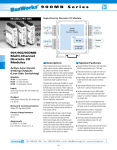
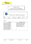
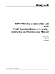
NuFloTM
Remote
Watercut Monitor
User Manual
Manual No. 40165001, Rev. B
© 2005 NuFlo Technologies, Inc. All information contained in this publication is
confidential and proprietary property of NuFlo Technologies, Inc. Any reproduction
or use of these instructions, drawings, or photographs without the express written
permission of an officer of NuFlo Technologies, Inc. is forbidden.
All Rights Reserved.
Printed in the United States of America.
Manual No. 40165001, Rev. B
June 2005
Table of Contents
Section 1—Description............................................................................................ 3
Introduction ............................................................................................................................................. 3
AC and DC Power Options ...............................................................................................................3
Other Features ..................................................................................................................................4
Specifications ......................................................................................................................................... 4
Section 2—Installation ............................................................................................ 7
Mounting the Remote Watercut Monitor................................................................................................. 7
Setting the Current Mode ....................................................................................................................... 8
Wiring the Remote Watercut Monitor ..................................................................................................... 9
10- to 30-VDC Model in Current Source Mode ...............................................................................11
10- to 30-VDC Model in the Current Sink Mode .............................................................................13
100- to 240-VAC Model in the Current Source Mode .....................................................................15
100- to 240-VAC Model in the Current Sink Mode..........................................................................16
Installing the Capacitance Probe.......................................................................................................... 18
Section 3—Setup and Operation .......................................................................... 22
Powering Up the Remote Watercut Monitor......................................................................................... 22
Configuring the Remote Watercut Monitor ........................................................................................... 23
Accessing with a Security Code......................................................................................................24
Selecting Probe Size .......................................................................................................................25
Setting a Security Code...................................................................................................................26
Configuring the Analog Output ............................................................................................................. 27
Calibrating the Capacitance Probe....................................................................................................... 29
Operating the Remote Watercut Monitor.............................................................................................. 29
Error Detection ................................................................................................................................30
Section 4—Spare Parts List .................................................................................. 31
June 2005
1
Safety Symbols
The following safety symbols are used in this manual and displayed on the instrument to alert users to
potential hazards. Take appropriate precautions to avoid personal injury.
Symbol
Description
Earth ground / intrinsically safe ground
Protective ground / power supply ground
Alternating current
Direct current
Caution: Risk of electric shock
Caution: Risk of danger
2
June 2005
Section 1
Description
Introduction
The Remote Watercut Monitor provides an analog signal that represents percent watercut. The fieldproven NuFlo Capacitance Probe is used to determine the percent watercut. As the Capacitance Probe
senses an emulsion’s dielectric properties, it generates a frequency that varies with the percentage of
water in the emulsion stream. The Capacitance Probe is designed to operate with fluid temperatures
up to 300°F (150°C). The Remote Watercut Monitor contains the power supply and safety barrier for
the capacitance probe, which is powered with the same cable used to receive the frequency signal.
The 4-20 mA signal generated by the Remote Watercut Monitor allows the percentage of watercut to
be read by other equipment.
The Remote Watercut Monitor is housed in a weatherproof fiberglass enclosure, suitable for
mounting to a bulkhead or a pole (Figure 1).
Figure 1—Front and side views of the Remote Watercut Monitor
AC and DC Power Options
The Remote Watercut Monitor is a four-wire instrument operating on 10- to 30-VDC or 100- to 240VAC power. Both the AC- and DC-powered models allow the user to configure the Remote Watercut
Monitor for Sink or Source current. When the Output Mode Select switch is set to Source mode, the
monitor is electrically configured to supply power to the 4-20 mA loop, allowing the user to feed the
June 2005
3
4-20 mA analog signal to any device without the need for loop power. For applications in which loop
power is embedded into the receiving device, the Output Mode Select Switch is set to Sink mode.
The Sink mode setting electrically configures the Remote Watercut Monitor for applications where
the user supplies power to the current loop.
These settings are described in detail in Section 2, Installation.
Other Features
The Remote Watercut Monitor is configured with pushbuttons and an LCD mounted on the circuit
assembly. (See Figures 2 and 3 on pages 3 and 4.) The LCD displays the percent watercut while the
unit is operating and provides user prompts in the configuration mode. A security access code
prevents unauthorized personnel from altering the configuration data in the instrument. The security
code may be disabled if this feature is not required.
The circuitry also contains an EEPROM, which saves the configuration data in the event of a power
failure.
Specifications
4
Enclosure
CSA/UL Type 4X
Environment
2000 m altitude max.
Internal Pollution Degree 2 rating
Watercut Range
0 to 100 percent (may be user programmed for other ranges,
provided that the difference between the minimum and maximum
watercut is at least 25 percent)
Input Power
10 to 30 VDC at 20 to 40 mA OR 100 to 240 VAC (50 to 60 Hz) at
35 to 75 mA (depending on model selected)
Operating Temperature
-20° to 60°C (-4° to 140°F)
LCD Display
Percent watercut, 0.3-in. character height
Update period: 1 second
Keypad
5 board-mounted momentary pushbutton switches
Inputs
Frequency signal from NuFlo Capacitance Probe
Intrinsically safe (Exia) input
Outputs
Isolated 4-20 mA, 2-wire loop representing percent watercut
16-bit resolution, 0.05 % of full scale at 25°C
50 PPM/°C temperature drift
Update period: 0.5 seconds
DAC calibration via keypad.
Compliance voltage: 8.5 VDC
Maximum load:
AC model in Source mode – 800 ohms
AC model in Sink mode – 100 to 1100 ohms dependent on
loop
supply voltage
DC model in Source mode – 100 to 1100 ohms dependent on
instrument supply voltage
DC model in Sink mode – 100 to 1100 ohms dependent on
loop supply voltage
June 2005
Figure 2—Nomenclature for DC-powered Remote Watercut Monitor (interior)
June 2005
5
Figure 3—Nomenclature for AC-powered Remote Watercut Monitor (interior)
6
June 2005
Section 2
Installation
Mounting the Remote Watercut Monitor
The weatherproof fiberglass enclosure that houses the Remote Watercut Monitor can be mounted to a
sturdy vertical flat surface (bulkhead) using four mounting holes on the back of the enclosure or to a
2-in. pole using an optional pole-mount kit.
Before mounting the Remote Watercut Monitor, check the following:
• Verify that the location of the area is not hazardous. The Remote Watercut Monitor is
designed to be located in non-hazardous locations only.
• Be sure that the vertical mounting surface is adequately braced to support the size and weight
of the instrument. The dimensions are shown in Figure 4.
Figure 4—Mounting dimensions for the Remote Watercut Monitor
June 2005
7
•
•
Ensure that the planned mounting height will allow easy viewing of the LCD display and
easy access to the pushbutton switches.
Ensure that the mounting location will provide adequate space for fully opening the front
door for access during wiring, maintenance, and calibration.
Setting the Current Mode
The Remote Watercut Monitor is a four-wire instrument that can be powered with 10- to 30-VDC or
100- to 240-VAC current. The procedure for wiring the unit depends on the power source (AC/DC)
and the current mode required for a specific application. Therefore, the current mode must be selected
before wiring can be installed.
To set the current mode, perform the following steps:
1. Locate the Output Mode Select switch inside the enclosure, beneath the DC-to-DC converter
circuit assembly (Figure 5). This switch should be set once during installation and left in one
position for as long as the instrument remains in a given location. The switch is positioned in
a discreet location to prevent inadvertent changing of the switch position during operation.
2. Remove the four Philips head screws from the DC-to-DC converter circuit assembly.
3. Gently lift the circuit assembly away from the baseplate and let it rest on its side (Figure 5),
taking care not to break or loosen the attached wiring.
4. Set the Output Mode Select Switch to the position required for the specific application (sink
or source).
5.
Reattach the DC-to-DC converter to the baseplate with the four Philips screws.
Figure 5—DC/DC converter circuit assembly (tilted upward) and the Output Mode Select
switch
8
June 2005
Wiring the Remote Watercut Monitor
The Remote Watercut Monitor requires power, a Capacitance Probe signal, and 4-20 mA output
connections for proper operation. It can be wired in four different configurations, depending on the
power source (AC/DC) and the current mode (Sink or Source) required. Field wiring diagrams and
maximum loop load resistance calculations are provided in this section for each of the four possible
configurations:
•
•
•
•
10- to 30-VDC model in Current Source mode
10- to 30-VDC model in the Current Sink mode
100- to 240-VAC model in Current Source mode
100- to 240-VAC model in the Current Sink mode
Important— Use of equipment in a manner other than that specified by NuFlo may impair any
protection afforded by the equipment. NuFlo bears no legal responsibility for the performance
of a product that has been serviced or repaired with parts that are not authorized by NuFlo.
Before you attempt to make field connections, verify that you are referencing the proper
instructions for the appropriate power source and current mode. Refer only to the section that
pertains to your specific application.
Caution – All field wiring must conform to the National Electrical Code, NFPA 70, Article 5014(b) for installations within the United States or the Canadian Electric Code for installations
within Canada. Local wiring ordinances may also apply. All field wiring must have a wire
range of 22 to 14 AWG and terminal block screws must be tightened to a minimum torque of 5
to 7 in-lbs. to secure the wiring within the terminal block. Only personnel who are experienced
with field wiring should perform these procedures.
Non-Intrinsically Safe Wiring
Non-intrinsically safe field wiring—the 4-20 mA loop and power supply wiring—enters the enclosure
through the left conduit hub at the bottom of the enclosure and connects to a terminal block at the
bottom of the baseplate inside the enclosure (Figure 6).
All external power supply wiring is to be 16-gauge or larger. The external power supply (customer
supplied) will include a disconnect switch or circuit breaker rated 13 A or less, located within easy
reach of the operator. The disconnect switch or circuit breaker must be clearly marked as the
disconnect for the external power supply.
The ground lug on the left side of the enclosure must be properly connected to an earth ground.
Intrinsically Safe Wiring
Intrinsically safe field wiring—the coaxial cable from the capacitance probe and the intrinsically safe
ground wire—enters the enclosure through the right conduit hub at the bottom of the enclosure. The
coaxial cable connects to the IS safety barrier inside the enclosure, and the IS ground wire connects to
the ground lug on the safety barrier support bar (Figure 6).
The Capacitance Probe generates a nominal 1-MHz high-frequency signal. Therefore, only coaxial
cable should be used between the Remote Watercut Monitor and the Capacitance Probe.
June 2005
9
The intrinsically safe ground must be 12-gauge stranded or larger CSA-approved wire with green
insulation, and must be segregated by a minimum of 50 mm from all non-intrinsically safe wiring.
Figure 6—Wiring locations for Remote Watercut Monitor
10
June 2005
10- to 30-VDC Model in Current Source Mode
Instruments that are powered by 10 to 30 VDC and are required to feed the 4-20 mA analog signal to
an end device without the need for loop power (current-sourcing) are wired as follows. These
instruments can source the 4-20 mA analog signal into a loop load of 100 to 1100 ohms, depending
on the voltage supplied to the instrument’s 10- to 30-VDC power terminal.
Field wiring of the DC model in Source mode is shown at right.
Important—Ensure that the Output Mode Select switch is set to the Source position.
CAPACITANCE
PROBE
+
4 - 20 mA
LOAD
G
SI
G
10-30 VDC
POWER
+
ND
RG-58 C/U
coaxial cable
+
4
+
-
10-30 VDC POWER
+
-
3
SAFETY
BARRIER
4 - 20 mA OUTPUT
IS GROUND
LUG
IS GROUND
REMOTE WATERCUT MONITOR
DC-POWERED MODEL CONFIGURED FOR CURRENT SOURCE MODE
June 2005
11
The maximum loop
resistance can be calculated
with the following formula
and graph.
Loop Voltage – 8
RL =
0.02
In DC-powered
current-source applications,
the loop voltage is the voltage
applied to the 10- to 30-VDC
power terminals.
The chart at right depicts this
relationship.
12
June 2005
10- to 30-VDC Model in the Current Sink Mode
Instruments that are powered by 10 to 30 VDC and receive loop power for the 4-20 mA analog signal
from the end device (current-sinking) are wired as shown below.
Important—Ensure that the Output Mode Select switch is set to the Sink position.
-
CAPACITANCE
PROBE
USER SUPPLIED
POWER SOURCE
12 TO 30 VDC
+
+
4 - 20 mA
LOAD
D
GN
10-30 VDC
POWER
G+
SI
RG-58 C/U
coaxial cable
+
4
+
-
10-30 VDC POWER
+
-
3
SAFETY
BARRIER
4 - 20 mA OUTPUT
IS GROUND
LUG
IS GROUND
REMOTE WATERCUT MONITOR
DC-POWERED MODEL CONFIGURED FOR CURRENT SINK MODE
June 2005
13
As is common with currentsinking devices, the loop
voltage determines the
maximum loop resistance.
The formula and graph below
define the loop voltage
requirement on the basis of
total loop resistance.
Loop Voltage – 8
RL =
0.02
In DC-powered current-sink
applications, the loop voltage
is the voltage of the usersupplied power source for the
current loop.
The chart at right depicts this
relationship.
14
June 2005
100- to 240-VAC Model in the Current Source Mode
Instruments that are powered by 100 to 240 VAC and feed the 4-20 mA analog signal to an end
device without the need for loop power (current-sourcing) are wired as shown below.
These instruments can source the 4-20 mA analog signal into a maximum loop load of 800 ohms.
Important—Ensure that the Output Mode Select switch is set to the Source position.
RISK OF ELECTRIC SHOCK. Exercise caution while installing AC power
supply wiring. Ensure that all disconnect switches are in the OFF position
before connecting wiring.
4 - 20 mA
LOAD
+
CAUTION
HOT
CAPACITANCE
PROBE
D
GN
G
SI
+
100 - 240 VAC
COM
POWER
RG-58 C/U
coaxial cable
4
COM HOT
100-240 VAC INPUT
+
3
-
4 - 20 mA OUTPUT
SAFETY
BARRIER
IS GROUND
LUG
IS GROUND
REMOTE WATERCUT MONITOR
AC-POWERED MODEL CONFIGURED FOR CURRENT SOURCE MODE
June 2005
15
100- to 240-VAC Model in the Current Sink Mode
Instruments that are powered by 100 to 240 VAC and receive loop power for the 4-20 mA analog
signal from the end device (current-sinking) are wired as shown below.
Important—Ensure that the Output Mode Select switch is in the Sink position.
CAUTION
RISK OF ELECTRIC SHOCK. Exercise caution while installing AC power
supply wiring. Ensure that all disconnect switches are in the OFF position
before connecting wiring.
-
USER-SUPPLIED
POWER SOURCE
12 TO 30 VDC
+
+
CAPACITANCE
PROBE
4 - 20 mA
LOAD
HOT
D
GN
G+
SI
100 - 240 VAC
COM
POWER
RG-58 C/U
coaxial cable
4
COM HOT
100-240 VAC INPUT
+
3
-
4 - 20 mA OUTPUT
SAFETY
BARRIER
IS GROUND
LUG
IS GROUND
REMOTE WATERCUT MONITOR
AC-POWERED MODEL CONFIGURED FOR CURRENT SINK MODE
16
June 2005
As is common with currentsinking devices, the loop power
is governed by the total loop
resistance. The graph below
defines the loop power
requirement on the basis of total
loop resistance. The relationship
of total loop resistance to the
loop voltage is as follows:
Loop Voltage – 8
RL =
0.02
In AC-powered current sink
applications, the loop voltage is
the voltage of the user-supplied
power source for the current
loop.
The chart at right depicts this
relationship.
June 2005
17
Installing the Capacitance Probe
The Capacitance Probe consists of a metal tube approximately 10 in. long, ranging in diameter sizes
of 2 in., 3 in., 4 in., and 6 in. with various end connections. An antenna assembly (coated metal rod) is
suspended in the center of the tube and insulated from the body, forming a coaxial capacitance cell.
An electronic circuit board mounted atop the tube is electrically connected to the antenna and the
body of the probe. The circuit board contains an oscillator for generating a frequency.
As a homogenous emulsion of oil and water flows through the probe body, the oscillator frequency
varies proportionally with the percent of water in the emulsion. The dielectric constant of the
emulsion is directly proportional to the percent of water contained within the emulsion. Due to the
physical and chemical properties of the emulsion, which vary with temperature and emulsion
constituents, the accuracy of the instrument is best at lower percentages of water and decreases as the
percentage of water increases. The Capacitance Probe is less accurate at water percentages above 50
percent because the oil/water emulsion enters a water-external phase and shorts out the capacitance
cell formed between the antenna and the body of the probe.
Because emulsion constituents vary, the Capacitance Probe must be calibrated in the field with the oil
that will be flowed through it, for optimum accuracy. The Capacitance Probe circuitry facilitates this
calibration by providing a variable trimmer capacitor to adjust the oscillator frequency.
The Capacitance Probe must be installed vertically as shown below in Figure 7. It may be installed
with either end up. In a separator application, the probe must be located upstream of the dump valve
and should be as close to the separator as possible, to ensure that it is always filled with fluid.
As shown in the above wiring diagrams, RG-58 C/U coax cable must be run between the Capacitance
Probe and the Remote Watercut Monitor. Lengths of several hundred feet are permissible.
Termination of the wiring is straightforward; follow the wiring diagram designations. Be certain to
protect the coax cable from traffic and moisture.
Figure 7—Installation of the NuFlo Capacitance Probe
18
June 2005
Mounting dimensions and part numbers for various NuFlo probe types are provided in the drawings
and tables below.
Capacitance Probe Dimensions—NPT Male Threaded Ends
Nom. Size
Thread
in. (mm)
Type
2
2-in. API LP
(50)
Max. WP
psi (MPa)
1000
(6.9 Mpa)
Part No.
A
100003563 10.00
(254)
B
2.37
(60.2)
C
D
E
8.23
6.21
3.49
(209) (157.7) (88.6)
Capacitance Probe Dimensions—Victaulic Grooved Ends
Nom. Size
in. (mm)
2
(50)
3
(80)
June 2005
Groove
Type
2-in. ES
3-in. ES
Max. WP
psi (MPa)
1000
(6.9 Mpa)
1000
(6.9 Mpa)
Part No.
A
B
C
D
E
F
G
H
100012107 10.00
2.37
8.23
6.21
2.25 0.255 0.562 3.49
(254) (60.2) (209) (157.7) (57.2) (6.5) (14.3) (88.6)
101246333 12.00
3.50
9.16
6.76
3.34 0.255 0.562 4.04
(304.8) (88.9) (232.7) (171.7) (84.8) (6.5) (14.3) (102.6)
19
Capacitance Probe Dimensions—Ring Joint Carbon Steel Flanged Ends
Flange Size (ANSI)
in. (mm)
lb
2
600
(50)
Max. WP
psi (MPa)
1480
(10.20)
H
Bolt Qty.
Dia.
Part No.
A
B
C
D
E
F
G
I
Angle, °
100063015 10.00
6.50
10.11
6.21
4.25
1.00 0.25
8
3/4
3.49
22.5
(254) (165.1) (256.8) (157.7) (108) (25.4) (6.4)
(19.1) (88.6)
Capacitance Probe Dimensions—Raised-Face Carbon Steel Flanged Ends
Flange Size (ANSI)
in. (mm)
lb
2
150
(50)
2
300
(50)
2
600
(50)
3
150
(80)
3
300
(80)
3
600
(80)
4
150
(100)
4
300
(100)
4
600
(100)
6
150
(150)
6
300
(150)
20
Max. WP
psi (MPa)
285
(1.96)
740
(5.10)
1480
(10.20)
285
(1.96)
740
(5.10)
1480
(10.20)
285
(1.96)
740
(5.10)
1480
(10.20)
285
(1.96)
740
(5.10)
Part No.
A
100012108 10.00
(254)
100063014 10.00
(254)
100012109 10.00
(254)
101004189 12.00
(304.8)
100063018 12.00
(304.8)
100063017 12.00
(304.8)
100063019 12.00
(304.8)
100063020 12.00
(304.8)
100063021 12.00
(304.8)
100063022 12.00
(304.8)
100063023 12.00
(304.8)
B
6.00
(152.4)
6.50
(165.1)
6.50
(165.1)
7.50
(190.5)
8.25
(209.6)
8.25
(209.6)
9.00
(228.6)
10.00
(254)
10.75
(273.1)
11.00
(279.4)
12.50
(317.5)
C
9.86
(250.4)
10.11
(256.8)
10.11
(256.8)
11.17
(283.7)
11.54
(293.1)
11.54
(293.1)
12.42
(315.1)
12.92
(328.2)
13.30
(337.8)
14.50
(368.3)
15.25
(387.4)
D
6.21
(157.7)
6.21
(157.7)
6.21
(157.7)
6.77
(172)
6.77
(172)
6.77
(172)
7.27
(184.7)
7.27
(184.7)
7.27
(184.7)
8.35
(212.1)
8.35
(212.1)
E
3.62
(91.9)
3.62
(91.9)
3.62
(91.9)
5.00
(127)
5.00
(127)
5.00
(127)
6.19
(157.2)
6.19
(157.2)
6.19
(157.2)
8.50
(215.9)
8.50
(215.9)
F
0.69
(17.5)
0.81
(20.6)
1.00
(25.4)
0.88
(22.4)
1.06
(26.9)
1.25
(31.8)
0.88
(22.4)
1.19
(30.2)
1.5
(38.1)
0.94
(23.9)
1.38
(35.1)
H
G
Bolt Qty.
0.06
4
(1.6)
0.06
8
(1.6)
0.25
8
(6.4)
0.06
4
(1.6)
0.06
8
(1.6)
0.25
8
(6.4)
0.06
8
(1.6)
0.06
8
(1.6)
0.25
8
(6.4)
0.06
8
(1.6)
0.06
12
(1.6)
Dia.
3/4
(19.1)
3/4
(19.1)
3/4
(19.1)
3/4
(19.1)
7/8
(22.2)
7/8
(22.2)
3/4
(19.1)
7/8
(22.2)
1
(25.4)
7/8
(22.2)
7/8
(22.2)
I
Angle, °
3.49
45
(88.6)
3.49
22.5
(88.6)
3.49
22.5
(88.6)
4.05
45
(102.9)
4.05
22.5
(102.9)
4.05
22.5
(102.9)
4.55
22.5
(115.6)
4.55
22.5
(115.6)
4.55
22.5
(115.6)
5.61
22.5
(142.5)
5.61
15
(142.5)
June 2005
June 2005
21
Section 3
Setup and Operation
Powering Up the Remote Watercut Monitor
After field wiring is completed, turn on the Remote Watercut Monitor using the Main Power Switch
on the upper right corner of the baseplate (Figure 8, page 23).
CAUTION: Never touch exposed wires. Only personnel who are experienced with field wiring
should attempt to make adjustments to the wiring.
Always use the Main Power Switch— not the power switch on the DC/DC converter—to powerup or power-down the Remote Watercut Monitor. The power switch on the DC/DC converter
must be set in the on position for the Remote Watercut Monitor to operate correctly.
The DC/DC converter board contains a fuse and a power switch that protect the Capacitance Probe.
•
•
In the AC-powered Remote Watercut Monitor, turning the DC/DC converter power switch off
while leaving the Main Power Switch on will power-down the Capacitance Probe interface board
and the 4-20 mA loop, causing the current output to drop to zero, but the AC power supply will
still be energized.
In the DC-powered Remote Watercut Monitor, turning the DC/DC converter power switch off
while leaving the Main Power Switch on will power-down the Capacitance Probe interface board,
but will leave the 4-20 mA loop energized, causing the current output to remain at the same
output level as it was immediately before the power was shut off.
There are three basic steps involved in making the Remote Watercut Monitor operational: configuring
the monitor, configuring the analog output, and calibrating the Capacitance Probe. Each step is
described in detail below.
22
June 2005
Figure 8—Location of the main power switch and the DC/DC converter power switch
Configuring the Remote Watercut Monitor
The first of three steps to making the Remote Watercut Monitor operational is to configure the
instrument by entering data. In the Configure mode, the upper line of the display will show prompts
consisting of abbreviated words. Each letter is formed with a 7-segment character. Due to the
limitations of a 7-segment character, some of the letters will be uppercase and some will be
lowercase. On the lower line of the display, the configuration data is entered. While in Configure
mode, each digit is changed one at a time. When a digit is selected to be changed, it will blink on and
off.
June 2005
23
In the following operation and configuration examples, display prompts and pushbutton names will
be shown in BOLD type. The prompts will be shown in uppercase and lowercase letters to
approximate their appearance on the display.
The pushbutton switches operate as follows:
ACCESS:
Press ACCESS while in the Run mode to place the instrument in the Configure
mode. Pressing ACCESS while in the Configure mode will return the instrument to
the Run mode. When returning to Run mode by pressing the ACCESS, any data that
has been input with the ENTER being pressed afterward will be saved to memory.
Any data that has been input without ENTER being pressed afterward will not be
saved. Data entered from a previous configuration will be retained.
STEP:
Pressing STEP allows the user to scroll to the left through the displayed digits to
select the digit to be changed. If the left-most digit is selected, pressing STEP again
selects the right-most digit. STEP is also used to toggle between selections.
INCR:
While entering numbers, INCR advances the value of the digit to be changed by one
from its initial value each time it is pressed. If INCR is pressed when the digit is
nine, the value rolls over to zero. INCR is also used to toggle between selections.
ENTER:
Pressing ENTER saves the displayed data for the current configuration function and
advances the display to the next configuration function.
RESET:
Pressing RESET causes a system reset in which all configuration data is set to
default values.
The steps required to configure the Remote Watercut Monitor are listed below. For clarity, the
explanation to each action is listed further down in this section:
1. Press ACCESS to enter the Configure mode.A segment test will be performed and the ROM
version will then be displayed. If a security code has been programmed, SEC.CodE will be
displayed. See the section below Accessing with a Security Code. If no security code is
programmed, the prompt ProbE will be displayed.
2. At the prompt ProbE, press INCR to select 2, 3, 4, 6, or oriG for the probe size. Press ENTER.
See the section below Selecting Probe Size for more information on probe selection
3. At the prompt voLt.oUt, press INCR to select oFF for the voltage output feature. After oFF is
selected, press Enter. The voltage output feature is not used on the Remote Watercut Monitor.
4. At the prompt CodE, press INCR to select oFF or on for the security code feature. If oFF is
selected, press ENTER. If on is selected, see the section Setting a Security Code.
5. At the prompt 4-20.oUt, press INCR to select on for the 4-20 mA output feature and press
ENTER. Go to the section Configuring the 4-20 mA Output to continue setup of the Remote
Watercut Monitor.
Accessing with a Security Code
Accessing the Configure mode of a Remote Watercut Monitor with a security code requires
knowledge of the security code.
1. Press the ACCESS key to enter the Configure mode.
24
June 2005
2. At the SEC.CodE prompt, use INCR and STEP keys to enter the security code. Press ENTER.
If the correct security code is entered, the user will be granted configuration access. If the
security code is incorrect, the device returns to Run mode.
Selecting Probe Size
Each size Capacitance Probe (2 in., 3 in., 4 in., and 6 in.) has a different response curve for the
frequency versus percent watercut as shown below. For this reason, the Remote Watercut Monitor is
internally programmed with the response curves of each of these probes. Typical response curves for
these various capacitance probe sizes are shown in Figure 9, page 26. The correct response curve for
the probe connected to the Capacitance Probe interface board must be selected to provide accurate
results.
The curves to be selected are:
•
2 in. – Select this curve for 2-in. probes with LCP coated antennas and Teflon bushings. (Probes
manufactured after 5/86)
•
3 in. – Select this curve for 3-in. probes with LCP coated antennas and Teflon bushings. (Probes
manufactured after 5/86)
•
4 in. – Select this curve for 4-in. probes with LCP coated antennas and Teflon bushings. (Probes
manufactured after 5/86)
•
6 in. – Select this curve for 6-in. probes with LCP coated antennas and Teflon bushings. (Probes
manufactured after 5/86)
•
Original – Select this curve for all sizes of NuFlo Capacitance Probes that have Delrin, ceramic,
®
®
or Ryton bushings and Ryton -coated antennas. (Probes manufactured before 5/86)
If the date of manufacture is not known, internals of the probe may be identified as follows:
•
•
Antennas
®
-
If the antenna is black or brown in color and 6 in. long, it is Ryton. Use the “original” curve.
-
If the antenna is tan in color and 7 in. long, it is LCP. Use the diameter of the probe body to
determine the correct size of the curve to input.
Bushings
®
-
If the bushing is brown or black, it is Ryton. Use the “original” curve.
-
If the bushing is yellow or cream in color, smooth and hard, it’s Delrin. Use the “original”
curve.
-
If the bushing is white or cream in color, hard and brittle, it is ceramic. Use the “original”
curve.
-
If the bushing is white, soft, and yielding to fingernail penetration, it is Teflon. For
identification purposes, all Teflon bushings made after late 1986 will have a circular groove
on the top surface. Use the diameter of the probe to determine the correct size of the curve to
input.
The diameter of the probe can easily be determined by the first number in the serial number prefix.
For example, the serial number 3SFP-844 denotes a 3-in. probe.
June 2005
25
1025
2" PROBE
3" PROBE
4" PROBE
6" PROBE
ORIGINAL
995
FREQUENCY OUTPUT (KHz)
965
935
905
875
845
815
785
755
0
10
20
30
40
50
60
70
80
90
100
PERCENT WATERCUT (%)
Figure 9—Response curves for various capacitance probe sizes
Setting a Security Code
Setting a security code will prevent altering of configuration data by unauthorized personnel and is
recommended to preserve data integrity. Any 4-digit number may be selected for the security code.
(Do not use 0000 as the security code since it is the default. If 0000 is set as the security code, the
user simply presses ENTER to access the Configure mode.) Select a number that is easy to
remember, but do not use a number that will be easy for unauthorized personnel to determine.
WARNING—Once a security code is set, it cannot be retrieved or erased should the user
accidentally misplace or forget the security code. If the security code is misplaced or forgotten,
contact your local NuFlo Sales Representative.
To enter a security code, perform the following steps:
1. Press ACCESS to enter the Configure mode.
2. Press ENTER until the CodE prompt appears to accept the current settings.
3. The lower line of the display will show oFF or on (factory default is oFF). Press INCR until on
is displayed to enable the feature. Press ENTER.
4. At the Ent.CodE prompt, use INCR and STEP to enter a 4-digit security code. The lower line
of the display will show the previously entered code (factory default code is 0000).
5. Press ENTER to return to Run mode.
26
June 2005
Configuring the Analog Output
The second step to making the Remote Watercut Monitor operational is to calibrate the 4-20 mA
circuitry and to establish the range of watercut that will be represented by the 4-20 mA to represent.
The Remote Watercut Monitor can be configured to represent any watercut range from 0 to 100
percent as long as the low engineering value and the high engineering value differ by at least 25
percent.
The low engineering value (typically configured for 0 percent watercut) may be configured for any
minimum desired percent watercut. A watercut equal to the low engineering value will result in an
output of 4 mA. During operation, if the flowing percent watercut falls below the minimum entered
watercut value, the current output will remain at 4.0 mA and the 4-20.oUt/Err Lo error message will
be displayed.
The high engineering value (typically configured for 100 percent watercut) may be configured to any
percent watercut that is at least 25 percent higher than the low engineering value. A percent watercut
equal to the high engineering value will result in an output of 20 mA. If the flowing percent watercut
rises above the high engineering value, the current output will go as high as 22 mA and the 420.oUt/Err Hi error message will be displayed.
Watercut percentages between the low and high engineering values will result in an output of current
between 4 mA and 20 mA according to the following calculation:
⎡
I MAX − I MIN
I OUT = ⎢
⎣WATERCUTHIGH − WATERCUTLOW
⎤
⎥ × [WATERCUTCURR − WATERCUTLOW ] + I MIN
⎦
Where:
I OUT = the output current
I MAX = the maximum current output which is 20 mA
I MIN = the minimum current output which is 4 mA
WATERCUTHIGH = the percent watercut high engineering value
WATERCUTLOW = the percent watercut low engineering value
WATERCUTCURR = the flowing percent watercut
In addition to defining the range of watercut, the user must adjust the output circuitry due to the
tolerance of the electronic components. This procedure is achieved with the keypad and ensures
maximum output accuracy. Figure 10 below illustrates the operation of the 4-20 mA output.
June 2005
27
Current Output (mA)
20
16
12
8
4
0
Low Engineering Value
High Engineering Value
Watercut (%)
Figure 10—4-20 mA output calibration range
CAUTION: Before performing any 4-20 mA calibrations, ensure that all peripheral equipment
connected to the 4-20 mA current loop is either disconnected or disabled. Calibrating and
testing the 4-20 mA output feature on the Remote Watercut Monitor with the peripheral
equipment in operation may cause false alarms or erroneous operation of the peripheral device
or associated equipment. This is due to the fact that during calibration, the Remote Watercut
Monitor outputs a value close to 4.000 mA to calibrate the zero point and a value close to 20.000
mA to calibrate the full scale.
Important: Configuring the output requires the use of an ammeter. The accuracy and resolution of
the ammeter determines the accuracy of the current output calibration of the Remote Watercut
Monitor. Use a recently calibrated ammeter traceable to NIST with a minimum resolution of two
decimal places.
To configure the engineering values and calibrate the 4-20 mA output circuitry, perform the
following steps.
1. Connect the ammeter in series within the 4-20 mA output loop. The Capacitance Probe does not
have to be connected to perform this procedure.
2. Press ACCESS to enter the Calibrate mode.
3. A segment test will be performed and the ROM version will then be displayed.
− If a security code has been programmed, SEC.CodE will be displayed. See the section
above, Accessing with a Security Code.
− If no security code was programmed, the prompt ProbE will be displayed.
4. Accept the current settings by pressing ENTER until the 4-20.oUt prompt appears.
5. Press INCR to toggle the bottom line to on in order to enable the feature. Press ENTER.
6. Set the ammeter to the highest resolution possible in the 4-20 mA range. At the i CAL.Lo
prompt, use INCR and STEP to enter the milliamp reading of the ammeter into the lower line of
the display. The lower line of the display will show the previous low value (factory default
4.000). Press ENTER.
7. At the i CAL.Hi prompt, use INCR and STEP to enter the milliamp reading of the ammeter into
the lower line of the display. The lower line of the display will show the previous high value
(factory default 20.000). Press ENTER.
8. At the i Eng.Lo prompt, use INCR and STEP to enter the low engineering value for the percent
watercut that is represented by 4 mA (e.g. 0). Press ENTER.
28
June 2005
9. At the i Eng.Hi prompt, use INCR and STEP to enter the high engineering value for the percent
watercut that is represented by 20 mA (e.g. 100). Press ENTER.
10. At this point, the 4-20 mA output has been calibrated. Pressing ACCESS exits the Configure
mode without making any further changes.
Calibrating the Capacitance Probe
The final step in making the Remote Watercut Monitor operational is to calibrate the Capacitance
Probe. The Capacitance Probe must be wired to the Remote Watercut Monitor electronics and the
monitor electronics must be configured and calibrated before the Capacitance Probe calibration is
initiated.
Optimal results are achieved when the Capacitance Probe is adjusted at operating temperature while
in operation. However, the probe may be calibrated while it is removed from the flow line. Accuracy
is maximized when the watercut of the emulsion sample comes closest to the 4 mA engineering value
(dry oil).
To calibrate the Capacitance Probe, perform the following steps:
1. Fill the probe completely with a known watercut sample volume of the same emulsion that the
probe will be used with.
2. Note the percent watercut displayed by the Remote Watercut Monitor.
−
−
If the Capacitance Probe watercut is correct, no adjustment of the Capacitance Probe is
required.
If the Capacitance Probe watercut is not correct, adjustment of the Capacitance Probe is
required. Proceed with step 3.
3. To adjust the Capacitance Probe, unscrew the pipe plug in the trimmer capacitor access hole and
adjust the trimmer capacitor on the Capacitance Probe circuit assembly just past the correct
watercut value.
4. Turn the trimmer the opposite direction just until the correct watercut value is indicated. The
calibration is complete; no further adjustment should be made.
5. Replace the pipe plug in the trimmer capacitor access hole.
Operating the Remote Watercut Monitor
The Remote Watercut Monitor has two modes of operation: Run mode and Configure mode.
In the Run mode, the Remote Watercut Monitor displays the percent watercut on the LCD and
outputs a corresponding analog signal based on its calibration. This is the normal operating mode for
the Remote Watercut Monitor.
If the Remote Watercut Monitor has not been configured, it must be configured before being placed
in service. See Configuring the Remote Watercut Monitor, page 11, for a step-by-step configuration
procedure.
June 2005
29
Error Detection
In the Run mode, the Remote Watercut Monitor informs the operator of detected errors. When an
error is detected, the word Error is displayed on the lower line of the display every other time that
the percent watercut value is updated.
To view the error, press INCR or STEP while the Error message is displayed. The first error will
appear on the upper line of the display.
Press INCR or STEP to check for additional errors. Each time INCR or STEP is pressed, the next
error will be displayed. When all errors have been displayed, pressing INCR or STEP will display
the first error again and the process can be repeated.
Press the INCR or STEP keys repeatedly to display all Error messages.
To return to the Run mode, press ENTER.
To enter the Configure mode to correct the errors, press ACCESS.
If more than one Error condition exists and an error is corrected, the next Error in sequence will be
displayed. When all Error conditions have been eliminated, the Remote Watercut Monitor
automatically returns to the Run mode.
There are four Error messages in the current version of firmware:
•
•
•
•
voLt.oUt/Err Hi
voLt.oUt/Err Lo
4-20.oUt/Err Hi
4-20.oUt/Err Lo
Note: The voltage output feature of the Capacitance Probe interface board is not used in the Remote
Watercut Monitor. After the voltage output is disabled during calibration, voLt.oUt/Err Hi,
voLt.oUt/Err Lo error messages will not be displayed.
The 4-20.oUt/Err Hi error message indicates the percent watercut has exceeded the high engineering
value set for the 4-20 mA output to the point that the current output has exceeded 22.0 mA. The
Error message appears on the lower line of the display only during the time that the condition exists.
When INCR or STEP is pressed during the error condition, the 4-20.oUt message appears on the
upper line of the display and the Err Hi message appears on the lower line of the display. This error
may indicate that the high engineering value is set too low for normal operating conditions. To
correct this error, change the high engineering value for the 4-20 mA output.
The 4-20.oUt/Err Lo error message indicates the percent watercut is below the low engineering value
set for the 4-20 mA output to the point that the output current has fallen below 4.0 mA. The Error
message appears on the lower line of the display only during the time that the condition exists. When
INCR or STEP is pressed during the error condition, the 4-20.oUt message appears on the upper line
of the display and the Err Lo message appears on the lower line of the display. This error may
indicate that the low engineering value is set too high for normal operating conditions. To correct this
error, change the low engineering value for the 4-20 mA output.
30
June 2005
Section 4
Spare Parts List
WARNING—Use of spare parts other than those identified by NuFlo voids CSA certification.
NuFlo bears no legal responsibility for the performance of a product that has been serviced or
repaired with parts that are not authorized by NuFlo.
The following spare parts are recommended for the Remote Watercut Monitor:
Quantity
Part Number
1
101238900
Capacitance Probe Interface Circuit Assembly
1
100079457
Power Supply Circuit Board
1
100035752
Safety Barrier, MTL 765
1
101236889
AC Power Supply ( AC powered models only)
5
101239754
Fuse, 0.25A for the Cap Probe Interface Circuit Board
5
100033669
Fuse, 2A for the Power Supply Circuit Board
1
101318809
Switch, Toggle, Main Power
June 2005
Description
31
32
June 2005
WARRANTY - LIMITATION OF LIABILITY: Seller warrants only title to the products,
software, supplies and materials and that, except as to software, the same are free
from defects in workmanship and materials for a period of one (1) year from the date
of delivery. Seller does not warranty that software is free from error or that software
will run in an uninterrupted fashion. Seller provides all software "as is". THERE ARE
NO WARRANTIES, EXPRESS OR IMPLIED, OF MERCHANTABILITY, FITNESS
OR OTHERWISE WHICH EXTEND BEYOND THOSE STATED IN THE
IMMEDIATELY PRECEDING SENTENCE. Seller's liability and Buyer's exclusive
remedy in any case of action (whether in contract, tort, breach of warranty or
otherwise) arising out of the sale or use of any products, software, supplies, or
materials is expressly limited to the replacement of such products, software,
supplies, or materials on their return to Seller or, at Seller's option, to the allowance
to the customer of credit for the cost of such items. In no event shall Seller be liable
for special, incidental, indirect, punitive or consequential damages. Seller does not
warrant in any way products, software, supplies and materials not manufactured by
Seller, and such will be sold only with the warranties that are given by the
manufacturer thereof. Seller will pass only through to its purchaser of such items the
warranty granted to it by the manufacturer.