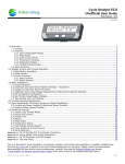
1
Cycle Analyst 3.0 p6
document version 3.0p6-g
2014.04.09
teklektik
Unofficial User Guide
This is a 'best effort' work intended as a temporary measure until formal documentation is available.
See the post “Cycle Analyst V3 Unofficial User Guide” for the most recent version of this document.
Selected text from the Grin Tech site is quoted in-line with colored background for reference; please review the
authoritative documentation on that site for more contemporary versions. Also see the Endless-Sphere.com
thread “Cycle Analyst V3 preview and first beta release” from which much of this material has been drawn.
Endless-Sphere.com
Unofficial CA V3 User Guide
Table of Contents
1.0 Overview............................................................................................................................................4
1.1 Concept........................................................................................................................................... 4
1.2 Features........................................................................................................................................... 4
1.2.1 User Configurable Presets......................................................................................................................4
1.2.2 Auto-Cruise Control.............................................................................................................................. 4
1.2.3 Limiting.............................................................................................................................................. 5
1.2.4 Temperature Sensing............................................................................................................................5
1.2.5 Diagnostic Displays...............................................................................................................................5
1.2.6 Throttle Enhancements......................................................................................................................... 5
1.2.7 External Controls................................................................................................................................. 5
1.2.8 RC Electronic Speed Controller (ESC) Support..........................................................................................6
1.2.9 Pedal Assist......................................................................................................................................... 6
1.2.10 High Voltage Monitoring...................................................................................................................... 6
1.2.11 Serial Communications........................................................................................................................ 6
1.2.12 Firmware Update and Setup Utilities......................................................................................................6
2.0 Console Operation and Display Screen Summary................................................................................7
2.1 Basic Button Navigation......................................................................................................................7
2.2 Mode Presets.................................................................................................................................... 7
2.3 Screen Summary...............................................................................................................................7
2.3.1 Setup Screens..................................................................................................................................... 7
2.3.2 Status Screens.....................................................................................................................................8
2.4 Display Averaging............................................................................................................................10
2.5 State of Charge Display....................................................................................................................10
3.0 Before You Start: Concepts and Considerations................................................................................11
3.1 Cycle Analyst Models: CA3-DP vs CA3-DPS..........................................................................................11
3.2 Operating Modes: Normal vs Legacy...................................................................................................11
3.3 Monitor-Only Mode...........................................................................................................................11
3.4 Conflicts with Controller Features.......................................................................................................12
3.5 Upgrading from a V2 to a V3.............................................................................................................12
4.0 Basic Installation (Install/Connect CA and Tune Throttle)................................................................13
4.1 Third Party Vendor Kit Installation / Configuration................................................................................13
4.2 Install Hardware..............................................................................................................................13
4.2.1 Connect Cycle Analyst to Controller.......................................................................................................13
4.2.1.1
4.2.1.2
4.2.1.3
4.2.1.4
4.2.1.5
4.2.1.6
Direct Connect: Controllers with CA Interface Connectors........................................................14
Direct Connect: Upgrading Controllers without CA Interface Connectors.....................................17
Installation with High Current External Shunt (Normal Mode)...................................................17
Installation with Cycle Analyst Molded External Shunt Module (Normal Mode)............................18
Installation with RC Electronic Speed Controller (Normal Mode)...............................................19
Installation with Multiple Controllers (2WD)...........................................................................19
4.2.2 Mount Console and Wheel Pickup..........................................................................................................20
4.2.3 Connect Throttle.................................................................................................................................20
4.3
4.4
4.5
4.6
Determine and Save Device-Specific Settings.......................................................................................21
Update CA with Most Recent Firmware................................................................................................22
Calibrate Current and Voltage Measurements (Make Device-Specific Settings)..........................................22
Configure Setup Parameters..............................................................................................................23
4.6.1 Set Up Baseline Configuration.............................................................................................................. 23
4.6.2 Set Throttle Input/Output Voltages....................................................................................................... 23
4.7 Test Throttle and Limit Settings (Interpreting Limit Flags)......................................................................26
4.8 Adjust Throttle Ramping...................................................................................................................27
4.9 Adjust Gain: Minimize Surging or Speed Oscillations.............................................................................27
4.9.1 Current and Power Gain (AGain, WGain)................................................................................................28
4.9.2 Speed Gain (PSGain, IntSGain, DSGain)................................................................................................28
5.0 Advanced Features...........................................................................................................................29
5.1 Battery Low Voltage Cutoff (LoVGain).................................................................................................29
5.2 Closed-Loop Throttle Modes..............................................................................................................29
5.3 eBrakes.......................................................................................................................................... 31
5.4 Auto-Cruise Control..........................................................................................................................33
5.5 Auxiliary Pot................................................................................................................................... 34
3.0p6-g
2/65
Endless-Sphere.com
Unofficial CA V3 User Guide
5.6 Pedal Assist.................................................................................................................................... 37
5.7 Temperature Sensor.........................................................................................................................42
5.8 High Voltage Vehicle Support.............................................................................................................43
5.9 Cycle Analyst as a Power Source........................................................................................................44
5.10 Serial Data Port............................................................................................................................. 46
6.0 Tips and Tricks.................................................................................................................................47
6.1 DC/DC Converters...........................................................................................................................47
6.2 DIY PAS Sensor / Adding Direction Output to a PAS Wheel.....................................................................47
6.3 Opening the Cycle Analyst Case.........................................................................................................47
6.4 Extending Cables.............................................................................................................................47
6.5 AutoTorqPAS – AutoPAS with RPM-Proportional Assist............................................................................48
6.6 PAS Assist Control without AUX Pot – DIY Virtual Torque Sensor.............................................................51
6.7 Using LM35 Temperature Sensors.......................................................................................................52
6.8 Operation in Wet or Cold Conditions...................................................................................................52
6.9 Displaying Wheel RPM......................................................................................................................52
6.10 Auto-Cruise as an Adjustable PAS Level.............................................................................................53
6.11 Determining Tire Circumference.......................................................................................................53
Appendix A. Calibrating the Cycle Analyst RShunt Value........................................................................54
A.1 The Calibration Correction Factor........................................................................................................54
A.2 Calibration Without Instruments.........................................................................................................54
A.3 Instrumented Calibration Using an Ah/Wh Meter...................................................................................54
A.4 Instrumented Calibration Using a Current Controlled Charger/Power Supply..............................................55
Appendix B.
Add/Remove Wheel Speed Pickup Sensor..........................................................................56
Appendix C. Summary of CA-DP Wiring for Controllers with Old/New Interface Types...........................57
C.1 “Large Screen Compatible” Controllers.................................................................................................57
C.2 “V2 Compatible” Controllers...............................................................................................................58
Appendix D. Tuning Speed Control Gain Parameters..............................................................................59
D.1 PID Controller Operation ...................................................................................................................59
D.2 Speed Gain Adjustment Procedure......................................................................................................60
Appendix E. Configurable Aux Pot 3-Position Switch Using Fixed Resistors............................................61
E.1 Grin Tech 3-Position Switch (Fixed Resistors)........................................................................................61
E.2 Custom DIY 3-Position Switch (Fixed Resistors).....................................................................................63
Appendix F. CA V3 Connector and PCB Images......................................................................................65
F.1 Connector Pinout...............................................................................................................................65
F.2 Pad Descriptions............................................................................................................................... 65
3.0p6-g
3/65
Endless-Sphere.com
1.0
1.1
Unofficial CA V3 User Guide
Overview
Concept
The Cycle Analyst V3 measures and displays detailed information about the battery, acts as a general purpose trip
computer, records and calculates statistics on vehicle performance, monitors and displays data from optional input
devices, and limits the motor controller based on the monitored and calculated data. This affords a single integrated
solution to display and control vehicle operation with all control passing to the motor controller via the throttle signal.
This approach allows any motor controller to be upgraded with advanced features like torque-sensing PAS or overtemperature power rollback.
In the role as intermediary between controller and accessory devices, the Cycle Analyst also processes the operator
throttle and combines it with other inputs to arrive at a single output throttle signal. This provides an opportunity to
provide options to enhance operator throttle operation. These options can materially improve the driving experience
by smoothing power application and mitigating uneven and quirky throttle response.
1.2
Features
The V3 is housed in the same Large Screen console as the V2 but offers expanded features using a more powerful
processor and increased memory.
1.2.1 User Configurable Presets
The V3 offers up to two Battery Presets that allow rapid reconfiguration when installing different battery packs.
Battery statistics are associated with each preset so unique historical information is maintained for each individual
pack.
Up to three Mode Presets are provided to allow easy selection of suites of preconfigured parameter settings. These
may be used to switch between different power limitations (e.g. legal, off-road), to enable/disable assist modes, or to
customize throttle behavior for different riding situations.
1.2.2 Auto-Cruise Control
The Cycle Analyst provides an auto-cruise control capability that holds the present throttle setting if the throttle
remains unchanged for a period of time. Auto-cruise releases on ebrake input or throttle application.
3.0p6-g
4/65
Endless-Sphere.com
Unofficial CA V3 User Guide
1.2.3 Limiting
The Cycle Analyst continually monitors three vehicle attributes: battery voltage, current, and speed. Four
configurable parameters (Low Voltage Cutoff, Current, Power, and Speed) provide limits beyond which the V3 will
reduce the throttle to alleviate the limit violation. All limits are always in play although any may be effectively
disabled by configuring it to an unattainably high value. Beyond these four core limits, other limits associated with
optional advanced features such as temperature monitoring and PAS assist may be similarly configured.
1.2.4 Temperature Sensing
The Cycle Analyst temperature sensor input supports either NTC (Negative Temperature Coefficient) thermistors or
linear devices like the LM335. In addition to displaying the temperature, the V3 moderates heat generation by
throttling back the controller as temperature rises through a configurable limit range.
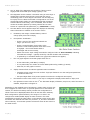
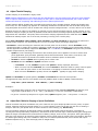
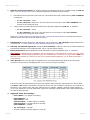
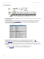
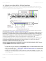
1.2.5 Diagnostic Displays
The Cycle Analyst has several displays designed to simplify setup and
problem resolution. The status screen to the right shows throttle input
and output voltages as well as an array of flags that indicate which of the
limiting parameters are presently in play and restricting controller power.
Other Setup screens display real time data values of related input
parameters. This allows the signals from throttle, 3-position switch, PAS,
and temperature devices to be inspected without external test equipment.
The display to the right shows the voltage from a custom external PAS
assist level adjustment knob.
1.2.6 Throttle Enhancements
The V3 provides three means to enhance throttle operation:
• throttle/controller voltage matching,
• throttle ramping, and
• alternative feedback-based throttle modes.
1.
Throttle dead zones and motor creep occur when the throttle output voltage range is not identical to the
throttle input range of the motor controller. The Cycle Analyst provides configuration options to match the
requirements of these two devices without additional test equipment.
2.
Configurable throttle ramping provides a means to smooth the application and removal of controller power.
This is of particular value to vehicles with powerful motors or with motors/drivetrains containing gears,
clutches, chains, etc. Ramping is universally applied to the generated Throttle Out signal and so affects all
operation, not just the operator throttle. This feature can make the bike more controllable and can safeguard
drivetrain components.
3.
Perhaps the most valuable throttle feature is the ability to employ one of three additional closed-loop feedback
modes: Current, Power, or Speed Throttle. In these modes the operator throttle is not used for direct control
but rather provides a 0-100% target level of the configured current, power, or speed limit for the Cycle
Analyst to achieve. The V3 runs the controller independently, monitoring speed, shunt, and/or battery voltage
and computing the necessary controller throttle voltage to achieve the operator target. This fly-by-wire
approach masks quirky controller/motor behavior by making difficult controller throttle adjustment the
responsibility of the CA, not the operator.
1.2.7 External Controls
The Cycle Analyst affords an optional input that may be used with an external control such as a 2 or 3 position switch
or potentiometer. This auxiliary input may be configured to switch configuration presets or to adjust current, power,
speed, or PAS limits. Off the shelf plug and play controls are available or custom controls may be fabricated.
3.0p6-g
5/65
Endless-Sphere.com
Unofficial CA V3 User Guide
1.2.8 RC Electronic Speed Controller (ESC) Support
The Cycle Analyst can provide either a voltage level or PWM signal as a controller throttle input to directly drive
either conventional vehicle controllers or RC ESCs (a separate ESC servo tester is not required). The CA can also act
as an ESC Battery Eliminator Circuit (BEC).
1.2.9 Pedal Assist
The Cycle Analyst supports both PAS cadence sensors and torque-sensing devices such as the Thun or TDCM bottom
brackets. Several PAS modes are available:
1.
Auto PAS: When pedaling is detected, the bike supplies a fixed configurable 'background' assist power level.
If the throttle is applied while pedaling, then the PAS signal is ignored and the throttle alone controls power.
Assist power is ON or OFF and does not vary with pedaling speed or effort.
2.
Throt PAS: There is no pedaling assist but you must be pedaling for the throttle to work.
3.
Torq PAS: Assist power is proportional to both crank rpm and a torque sensor (e.g. Thun BB), so the more
effort you exert the more power you get from the motor. If the throttle is applied while pedaling, then the
torque signal is ignored and the throttle alone controls power.
Configuration parameters allow specification of the maximum speed limit for assist and the maximum speed for
throttle use without pedaling. Together these parameters and modes can provide compliance with a variety of pedalec
legal requirements.
1.2.10 High Voltage Monitoring
Vehicles with high voltage traction batteries can pose safety issues if the traction battery voltage is routed directly to
the operator instruments. The Cycle Analyst provides an optional input to allow monitoring voltages up to 500v via
an external voltage divider while the CA itself is powered from a separate low voltage source such as a 12v DC/DC
converter. However, high and low voltage grounds remain shared so the CA is not fully isolated.
1.2.11 Serial Communications
The Cycle Analyst V3 provides a serial data port that continually sends live data such as voltage, throttle, distance,
speed, etc. This data can be collected by an external device or with a Cycle Analogger data recorder. When used with
an Analogger, complete trip and optional GPS (from the Analogger) data is recorded. The serial port also provides a
means to update the firmware or even to alter configuration parameters from an external device.
1.2.12 Firmware Update and Setup Utilities
Two interactive PC utilities are available for end-user operation (other platforms are supported depending on the
utility). Both communicate with the device via the serial communications port and the USB-TTL download cable
provided with the Cycle Analyst.
The Firmware Update Utility allows easy update with newer firmware versions. Firmware versions are available on the
Grin Tech web site.
The interactive Setup Utility maintains complete Cycle Analyst configurations as files which may be loaded to/from the
V3 to save or restore complete configurations. The utility allows configuration of all parameters normally accessible in
the CA native Setup mode and also provides access to other hidden features that impose Setup configuration limits or
exclude access to specific Setup screens. These hidden features can be used to enforce legal configuration or
otherwise limit access to critical settings. All lifetime and trip statistics are saved/restored with the Setup parameters
making the the utility a simple means to periodically archive historical vehicle and battery information.
3.0p6-g
6/65
Endless-Sphere.com
2.0
2.1
Unofficial CA V3 User Guide
Console Operation and Display Screen Summary
Basic Button Navigation
• Press right/left buttons to navigate Status or Setup Screens
• Press/hold left button to enter Setup
• Press/hold right button to reset trip statistics
• From the 'Trip Regen Stats' status screen, press/hold right button to reset peak trip statistics
2.2
Mode Presets
Mode and battery presets are configured in Setup and may be selected in Setup or at any time from the main status
screens using both buttons in 'hot swap' mode:
1.
Select Mode Presets by holding the left button then tapping the other button to sequence though presets.
2.
Select Battery Presets by holding the right button then tapping the other button to sequence though presets.
Mode presets may also be selected by means of a custom external 'preset switch' (see ' 5.5 Auxiliary Pot'). The CA
can be configured to power up with the either a fixed default or the mode preset in effect when last powered down.
Historical battery statistics (see 'Status Screens' below) are accumulated independently for each battery preset. By
assigning a separate battery preset to individual battery packs, unique historical data will be available for each.
2.3
Screen Summary
Although the images in this section were accurate at the time of publishing (3.0p6), they may become dated because
of firmware updates and are presented only to illustrate general content, style, and techniques.
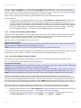
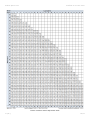
2.3.1 Setup Screens
The setup screens are divided into sections, each prefaced with a section preview screen. The preview screens
typically show an abbreviated summary of important parameters within the section.
3.0p6-g
7/65
Endless-Sphere.com
Unofficial CA V3 User Guide
Some preview screens display live data which can be identified by rapid blinking or flickering of the displayed value.
These screens are generally self-explanatory, but certain display features warrant special mention.
1.
The 'SETUP THROT OUT' screen (#4 above) shows the configured min/max output voltages followed by a
small sloping line. The steepness of the slope reflects the relative rate configured for ThrO->UpRate.
2.
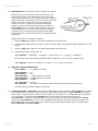
The Speedometer and PAS preview screens use animated glyphs to
indicate the live hi/lo values of digital inputs. The screen to the
right shows a speedometer with 3 poles (spoke magnets). The
small arrow adjacent to the tiny raised “P” points up/down
according to the hi/lo state of the SP input (wheel pickup). Proper
pickup operation can be easily verified by observing the arrow
while rotating the wheel. The PAS Preview Screen has similar
arrows indicating the hi/lo states of the RPM and Dir inputs.
Press-hold the right button on any preview screen to enter the section and
edit individual parameters. Each parameter is configured on an individual
screen. Advance to the desired parameter screen and press-hold the right
button to edit.
Note: Certain Setup parameters have global significance and are not part of any preset (e.g. tire circumference) while
others are preset-specific (e.g. number of battery cells) and may be set differently in each preset. To determine if a
parameter is global or preset-specific, see the most recent configuration summary file listed in this post. Individual
Setup parameters are described in detail on the Grin Tech V3 web page.
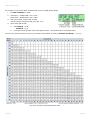
2.3.2 Status Screens
There are eleven Status screens which display information grouped by function. Some information (e.g. speed, Amps)
is displayed on more than one screen to give the operator a more comprehensive view without changing screens.
Most screens are self-explanatory, but some deserve a bit of clarification
1.
In PAS screens (#3 and #5 above) 'HW' refers to generated 'Human Watts' measured by the CA.
2.
'Rbatt' on the Battery screen (#10 above) refers to the calculated battery resistance which will normally vary
with age and temperature.
3.0p6-g
8/65
Endless-Sphere.com
3.
The 'In' label of the Diagnostic Screen blinks if Auto-Cruise is
engaged and the throttle input voltage (speed) is 'set'.
4.
The Diagnostic Screen contains a character string of Limit Flags. A
capital letter indicates that the limit is asserted and may be
moderating power to some degree. More than one limit flag may
be in play at once. When the throttle is configured for one of the
closed-loop throttle modes, the associated limit flag will appear
asserted almost continuously, even at standstill, since in these
modes the throttle operates by limiting Throttle OUT to some
fraction of a particular limit parameter (e.g. MaxCurrent = 100A).
5.
The Main Status screen appears simple but displays the following
status information in addition to the numeric values:
a.
the Battery Gas Gauge indicates battery state of
charge (SOC) from Full to Empty,
b.
the Operator Throttle Bar:
Unofficial CA V3 User Guide
• shows 0-100% of the configured Throttle IN
range (far left on 2nd line),
• shows a second blinking 'ghost' slider at the
selected 'cruise throttle' position when auto-cruise
is engaged - the normal throttle slider is
unchanged and moves normally,
• flashes if there the input voltage exceeds the configured value of ThrI->FaultVolt, indicating
a throttle fault voltage – typically caused by a broken throttle Gnd connection,
• is replaced by an animated ebrake lever glyph when ebrakes are applied,
c.
the bar graph adjacent to throttle graph shows one of:
• in Auto PAS mode, pedal RPM (0-120rpm)
• in Torq PAS mode, the number of Human Watts produced by pedaling (0-400W)
• otherwise, the bar graph is inactive.
d.
display elements flash to indicate significant status conditions:
• exceeding a limit causes the units to flash: 'kph/mph' flashes if over the configured speed limit,
'V' flashes if below LVC,
• the speed digits flash if the present speed is less than the configured Start Speed,
e.
the leftmost numeric value of the 2nd line may be configured to display either Watts or Amps, and
f.
the rightmost numeric value on the 2 nd line alternates display of distance, Amp hours, and if the sensor is
enabled, temperature in degrees C.
Depending on the installed suite of accessories, certain status screens may
be of negligible or limited value. To provide rapid access to information of
interest, the Preferences Setup section provides two configurations to
select screens to be displayed/hidden when at rest and when underway.
Both configurations operate similarly: the strings of 1's and 0's are
configured to enable/disable display of status screens in the order
navigated by pressing the right button. In the sample screens to the right,
all screens are visible at rest while only screens 1, 4, and 8 are accessible
when underway - three button presses will traverse them all and return to
the initial screen.
3.0p6-g
9/65
Endless-Sphere.com
2.4
Unofficial CA V3 User Guide
Display Averaging
Measurements for voltage, amperage, and temperature values are prone to jitter so the Cycle Analyst smooths
display of these values according to the Pref->Averaging Setup parameter. The configured value determines the
period of time over which consecutive data values are averaged; a new sample is obtained every 18msec and the
average is cleared and begun anew when the average is computed and the display is updated. Averaging affects only
the display – all other internal calculations use instantaneous measurement values.
2.5
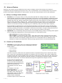
State of Charge Display
The Cycle Analyst 'gas gauge' display shows an estimate of the battery state of charge (SOC) based on these factors:
• battery chemistry
• battery voltage
• discharged Amp-hours
• battery capacity in Amp-hours
• calculated battery resistance
Battery chemistry is used to select internal parameters including the matching stored SOC curve which estimates
discharge level from open circuit voltage.
SOC can be estimated using either of two techniques:
• open circuit voltage and the stored SOC curve or
• the total expended Amp-hours.
Both approaches have strengths and weaknesses and the Cycle Analyst SOC algorithm combines these approaches to
give optimal accuracy over the entire discharge cycle. As part of this strategy, the Cycle Analyst calculates a battery
resistance (see Rbatt on status screen 10, ' 2.3.2 Status Screens') that is used to minimize gas gauge fluctuations
under varying load conditions.
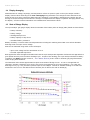
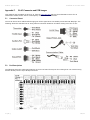
The illustration below shows approximate V3 Open Circuit State of Charge curves. To use an unsupported cell
chemistry, compare a discharge curve for the new cell to the supported curves in the illustration. Use a low rate
discharge curve (e.g. 0.2C) to better represent open circuit voltages. Choose an available existing curve that best
matches the new curve in the desired area of interest (this is often at the end-of-discharge).
3.0p6-g
10/65
Endless-Sphere.com
3.0
3.1
Unofficial CA V3 User Guide
Before You Start: Concepts and Considerations
Cycle Analyst Models: CA3-DP vs CA3-DPS
The Cycle Analyst V3 has two base models:
• 'CA3-DP' using speedometer signals from the controller (DD motors) and
• 'CA3-DPS' with wheel pickup wired into the console (DD or gear motors).
These models differ only in the wiring of the CA-DP cable and optional wheel sensor but are otherwise identical in all
aspects of electronics and firmware. Either model may be operated with direct connection to a controller or with an
external shunt. See 'Appendix B. Add/Remove Wheel Speed Pickup Sensor' for instructions to convert one model to
the other.
3.2
Operating Modes: Normal vs Legacy
The V3 can be operated in either of two modes: 'normal' mode or 'legacy V2' mode. In normal mode the operator
throttle (if present) connects to the CA and the CA provides the throttle signal to the controller. In legacy mode, the
operator throttle remains connected to the controller and the CA overrides the operator throttle only as needed to
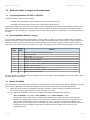
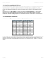
limit power in the same fashion as the earlier V2 models. The following table shows features available in each mode.
Normal
Mode
Legacy
Mode
Feature
PassThru / Current / Power / Speed Throttle
Throttle Ramping
Auto Cruise
PAS (Wheel or Torque Sensor)
AuxPot - PAS Level Adjust
AuxPot – Current / Power / Speed Limiting (throttle scaled for 100% rotation at limit)
AuxPot – Current / Power / Speed Limiting (limit at less than 100% throttle rotation)
AuxPot – Preset Selection
Current / Power / Speed Limiting
Temp Monitor with Power Rollback to limit Temperature
Ebrake Signal Pass Through
Although special circumstances may make legacy mode more desirable, most installations use normal mode to make
the full feature suite available.
3.3
Monitor-Only Mode
The Cycle Analyst has no configurable monitor-only mode where all limiting and throttle control is disabled. However,
either of these approaches will effectively disable CA throttle control while leaving monitoring operational.
1.
Follow the most convenient installation instructions for either normal or legacy V2 operation but sever or
do not connect the CA-DP connector throttle signal (pin 6 - green).
2.
OR - Follow the installation instructions for legacy V2 operation and make these settings:
ThrI->CntrlMode = Off (WOT), ThrO->MinOut = 4.90V, ThrO->MaxOut = 4.99V
In V2 legacy mode the CA limits by reducing the controller input voltage below that of the operator
throttle. The settings above restrict the CA to limit in the approximate range 5.5v to 5.6v which is too
high to affect normal operator throttle operation (1v to 4v) - so limiting is effectively disabled even
though the CA is still trying to do so. The diode drop (either Schottky or regular silicon diode) present in
the throttle circuit in V2 legacy mode raises the effective CA limit voltage 0.3v to 0.6v over the
configured values.
3.0p6-g
11/65
Endless-Sphere.com
3.4
Unofficial CA V3 User Guide
Conflicts with Controller Features
The Cycle Analyst and certain controllers implement advanced features such as auto-cruise, PAS, etc. However, if
interacting features are not controlled by same device, undetectable conflicts may arise that can lead to unexpected
or unsafe behaviors. The simple and preferred solution is to centralize all advanced features in one device.
An effective strategy is to restrict the controller to simple throttle-based motor control and to rely on the CA to
coordinate all advanced features. This is not to say that certain controller features cannot be made to operate with a
Cycle Analyst, but deeper knowledge of both controller an CA behavior is required (i.e. advanced users).
Here are some considerations for utilizing controller features (all are discouraged except ebrakes/regen):
• Ebrakes – Controller ebrakes temporarily suspend motor power when applied and also release auto-cruise,
suppress PAS, or activate regen if those features are present. Unless specifically required by a controller
feature, ebrake wiring need not be connected to the controller.
Ebrakes must be connected to the CA if using CA PAS or CA auto-cruise so those features are properly
disabled when braking.
• Auto-cruise – This controller feature applies motor power by means other than the operator throttle
connection. Attempts by the CA to limit power by manipulating the throttle will prove ineffective and can lead
to apparent deactivation of the operator throttle. This feature should not be used for safety reasons.
(See ' 5.4 Auto-Cruise Control' and ' 5.3 eBrakes')
• PAS – This controller feature applies motor power by means other than the operator throttle connection and
so may create control conflicts as the CA attempts to limit power by manipulating the throttle. Problems are
generally less acute than with auto-cruise, but CA-based PAS is preferred. If controller PAS is used, ebrakes
must (at least) be wired to the controller (see 'Install Using a CA Adapter Module ' and ' 5.3 eBrakes').
• 3-Speed Switch – This controller feature scales the operator throttle so that the maximum motor PWM (and
hence effective motor voltage) is limited. This will work normally for CA PassThru Throttle but can result in a
pronounced upper throttle 'dead zone' for the more desirable Current and Power Throttle modes. Using the
equivalent CA AuxPot feature will scale the reduced power range across 0-100% throttle rotation
(see ' 5.5 Auxiliary Pot'). Use of this controller feature is not recommended.
• Regen Braking – There are many controller regen implementations – here are two:
• Throttle-based Regen (Infineon Slip Current Charge Mode) applies regen braking when the throttle is
backed off and is only suitable for use with CA PassThru Throttle. It will conflict with any CA feature
where the CA controls the throttle programmatically (e.g. PAS, auto-cruise, Current/Power/Speed
Throttle). Use of this feature is not recommended.
• Ebrake activated regen requires that ebrakes are wired to the controller. Ebrakes must also be wired to
the CA or features that programmatically control the throttle may cause a power surge when ebrakes are
released (see ' 5.3 eBrakes').
3.5
Upgrading from a V2 to a V3
When upgrading from an existing V2 to a V3 it may be desirable to retain custom wiring instead of modifying and
installing the new V3 wiring. The supplied V3 CA-DP and pickup cables may be unsoldered from the V3 PCB and
replaced directly with existing V2 cables.
Older V2 CA-DP cable and speedometer pickups have the same cable color coding and are essentially identical
to those of the V3. The older V2 external shunt is an acceptable external shunt for V3 operation and the four
wires of the V2 shunt have the same color coding as the new V3 CA-DP cable/molded shunt combination. The
new V2/V3 molded shunt module does have an added breakout cable to make throttle wiring a bit easier, but
this can be achieved by other means.
Note: Although the V3 CA-DP connector is identical in form to that of the CA V2, there is a small difference in
operation of the throttle connection on pin 6. This difference accounts for why V2 models operate by 'limiting' the
operator throttle voltage while V3 models operate by 'providing' the throttle voltage (see 'Appendix C. Summary of
CA-DP Wiring for Controllers with Old/New Interface Types'). V2 and V3 models are not generally out-of-box plug
compatible.
Please follow the installation instructions in ' 4.0 Basic Installation (Install/Connect CA and Tune Throttle)' to ensure
that the new V3 operates properly in the old V2 environment.
3.0p6-g
12/65
Endless-Sphere.com
4.0
Unofficial CA V3 User Guide
Basic Installation (Install/Connect CA and Tune Throttle)
This section of the Guide presents step by step instructions to install the hardware and configure basic monitoring and
throttle operation. Relevant material is presented as it is required so completing all steps will not only yield a properly
operating Cycle Analyst but will provide sufficient background to tackle installation and configuration of more
advanced features. Please carefully follow the steps in order and without modification.
4.1
Third Party Vendor Kit Installation / Configuration
If the Cycle Analyst has been supplied or customized by a vendor (e.g. EM3EV) then follow the vendor instructions for
installation. Package or kit installations typically use:
• 'normal' mode V3 operation,
• a controller with a contemporary 'Large Screen Compatible' CA-DP interface to provide a simple plug and play
installation, and
• the same 'standard' cable connections as described below, although some minor wiring changes may exist
(e.g. use CA-DP yellow Spd wire to carry a signal from a temperature sensor).
Although the Setup parameter configuration described here may be performed for kit installations, the vendor may
have pre-configured the CA for proper out-of-box operation with the provided kit components. Consult the vendor to
determine what configuration is already in place. At the least, verifying throttle tuning may be advisable.
IMPORTANT: Vendor Setup parameter settings are not the normal CA 'defaults' and may not be available from any
source, including the vendor. Before making changes, use the Setup Utility (see ' 1.2.12 Firmware Update and Setup
Utilities') to read all settings from the CA and save them as a file. These unmodified baseline settings will allow the
CA to be restored to 'vendor original' condition if necessary.
4.2
Install Hardware
Except for the external wheel pickup, the CA3-DP and CA3-DPS models have identical console units with identical CADP cable, processor, and programming. This section applies apply to both models.
1.
If upgrading from a CA V2, record the value of the shunt in the existing system prior to removing the old CA.
2.
Familiarize yourself with V3 connections by briefly reviewing 'Appendix F.
CA V3 Connector and PCB Images'.
Note: The Cycle Analyst uses familiar JST-SM style connectors with tin-plated connection pins and locking
plastic shrouds. These connectors generally operate reliably with no special attention. However, users in
unusually wet or humid climates may find it useful after the CA is installed and tested to open the
connections, wipe the contact pins with Permatex dielectric grease (available in auto supply stores) and then
to re-seat the connectors. This optional dielectric grease can be refreshed as part of annual maintenance.
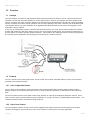
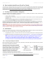
4.2.1 Connect Cycle Analyst to Controller
Basic Cycle Analyst operation requires power, shunt, speed input, and throttle output connections which are provided
by the 6 wire CA-DP cable and connector.
This connector can directly connect to a suitably
equipped controller or to an external shunt and
other controller wiring. The former can give a plug
and play solution suitable for most installations
while the second requires a bit more technical skill
and is employed where the controller lacks an
appropriate connector, where higher current
monitoring is required, or where multiple
controllers are operated from a single Cycle Analyst.
The following subsections detail both plug and play as well as more custom installations.
Connect the Cycle Analyst using only the single subsection appropriate for your situation then move on to
section 4.2.2 .
3.0p6-g
13/65
Endless-Sphere.com
Unofficial CA V3 User Guide
4.2.1.1 Direct Connect: Controllers with CA Interface Connectors
Controllers available from certain vendors (e.g. Grin Tech, EM3EV, Lyen) provide all required connections for power,
shunt, etc. via a single CA or 'Drainbrain' connector that mates with the CA-DP connector. However, there are two
distinct interface types that have electrically different throttle support – even though the connectors are identical:
• a newer 'Large Screen Compatible' interface (controllers produced after mid-2013) or
• an older 'V2 Compatible' interface (all controllers prior to mid-2013).
IMPORTANT: It is critical to correctly identify the controller interface type. Either interface style may be used with
the V3 in either normal or legacy mode, but electrical differences require very different connection techniques.
If the CA interface type is not known (the controller is not of recent manufacture or clearly labeled 'Large Screen
Compatible') then perform the following test to ascertain or verify the type:
1.
place the bike on a stand or invert it onto handlebars/seat so that the motor can run safely,
2.
plug the CA into the controller CA-DP interface and a throttle into the controller,
3.
power up the controller and CA,
4.
enter Setup, use all default CA settings, and configure:
5.
ThrO->MaxOutput = 2v and
ThrI->CntrlMode = Off(WOT),
6.
exit CA setup and be prepared to power down the controller.
7.
If the motor powers up spontaneously without manually applying throttle, then the controller
interface is 'Large Screen Compatible', otherwise is the earlier 'V2 Compatible' type.
8.
Power down the controller.
There are four combinations of the two interface types and two operating modes. Connect the Cycle Analyst to the
controller using whichever of the four following techniques (A, B, C, or D) is appropriate.
IMPORTANT: Differences in throttle connection schemes between the newer and older interface types may cause a
runaway throttle situation if a controller is simply plug-replaced with one of a different interface type. When replacing
a controller, it is imperative that the interface type and associated CA connections are reviewed to avoid improper or
dangerous operation.
A. Normal Mode Operation with 'Large Screen Compatible' Interface (V3 with New Controller)
This is a simple plug and play installation: plug the CA-DP cable into the mating controller CA connector.
Note: A CA Adapter Module may be
stacked on the CA-DP connector to
provide throttle and ebrake signals
to the controller (e.g. for regen
braking). See ' 5.3 eBrakes'.
Step Complete. Go to section ' 4.2.2
Mount Console and Wheel Pickup'.
3.0p6-g
14/65
Endless-Sphere.com
Unofficial CA V3 User Guide
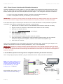
B. Normal Mode Operation with 'V2 Compatible' Interface (V3 Retrofit to Older Controller)
The CA-DP cable is plugged into the mating controller connector, but the CA-DP connector pin 6 throttle signal must
be severed and re-routed to the controller throttle input connector. There are many means to accomplish this - five
examples are shown below. Select and implement one option (Cases 1, 2, or 5 are recommended):
1.
Modify the controller wiring to bypass the V2 style interface and provide a 'V3 Compatible' interface instead.
The illustration below shows three means to achieve this.
a. Case 1: Pin 6 of the
controller CA connector is
re-routed to the 'Sense'
pin of a mating throttle
connector and plugged
into the controller. The
controller can be restored
to normal operation by
instead plugging in an
operator throttle.
b. Case 2: Pin 6 of the
controller CA connector is
routed directly to the
controller throttle 'Sense'
input wire and a 1K
resistor is added as
shown. This converts the
controller to the newer
'Large Screen Compatible'
interface so it will work
with either V2 or V3 Cycle
Analysts.
c. Case 3: This is a
simplified version of
Case 1 without the
connector. The throttle
and CA interface
connectors must not be
plugged in at the same
time – use one or the
other – not both.
2.
Or Modify the CA-DP cable by removing the heatshrink from the CA-DP connector, sliding out pin 6, then
seating pin 6 into a mating connector for the controller throttle input.
3.0p6-g
15/65
Endless-Sphere.com
3.
Unofficial CA V3 User Guide
Or Install Using a CA Adapter Module from Grin Tech. This breaks out the throttle connection and contains
logic to recover the ebrake signal from the throttle signal. The module operates as a pass-through so ebrakes
applied to the Cycle Analyst are also applied to the controller, making regen braking possible.
Step Complete. Go to section ' 4.2.2 Mount Console and Wheel Pickup'.
C. V2 Legacy Mode Operation with 'Large Screen Compatible' Interface
The Cycle Analyst V3 CA-DP cable interface is first modified so that it is the electrical equivalent of the legacy V2
interface.
• Open the case
(see ' 6.3 Opening the Cycle Analyst Case').
• Expose the Thd and ThO PCB pads by gently bending
the square brown polyfuse upright.
• Unsolder the CA-DP cable green throttle wire from the
ThO pad and solder it to the Thd pad.
• Reposition the brown polyfuse and close the console
case.
Next, since a 'Large Screen
Compatible' controller will operate
either a V2 or V3 in their respective
'normal' modes, the V3 with
modified V2 style interface can now
be directly plugged into the
controller CA connector and it will
behave in legacy V2 mode.
Step Complete. Go to section
' 4.2.2 Mount Console and Wheel
Pickup'.
3.0p6-g
16/65
Endless-Sphere.com
Unofficial CA V3 User Guide
D. V2 Legacy Mode Operation with 'V2 Compatible' Interface
This is a simple plug and play installation – plug the CA-DP cable into the mating controller cable as shown above. No
Cycle Analyst or controller modifications are required.
In this case, the unmodified V3
behaves in legacy V2 mode because
that is the only mode the controller
interface can support.
Step Complete. Go to section
' 4.2.2 Mount Console and Wheel
Pickup'.
4.2.1.2 Direct Connect: Upgrading Controllers without CA Interface Connectors
A CA interface connector may be added to a controller to allow simple plug and play CA connection as described in the
previous section. The modification can be done internal to the controller or exclusively to external controller wiring.
Follow the directions in the separate document “Adding a Controller 'Large Screen Compatible' CA Interface” then
return to ' 4.2.1.1 Direct Connect: Controllers with CA Interface Connectors' to connect the Cycle Analyst.
4.2.1.3 Installation with High Current External Shunt (Normal Mode)
The High Current model attaches to a 3rd party shunt resistor and the positive battery lead.
IMPORTANT: The shunt must be connected to the ground side of the battery; connection of the shunt to the positive
side of the battery can damage the circuitry.
Wire a male JST-6 connector as
illustrated to the right. The shunt and
Cycle Analyst S+ connections must be
arranged as shown relative to Vbatt- to
give the proper forward/regen current
sensing.
The CA Gnd (pin 2) must be connected
to Controller Gnd to improve the quality
of ground-relative signals (e.g. throttle
or motor temperature sensors that share
Controller Gnd wiring with hall sensors).
The Spd wire on CA-DP pin 5 can
optionally be tied to any motor hall wire
(between hall connector and controller)
as an alternative to using a wheel pickup.
Connect the new connector to the Cycle Analyst.
Note: A CA Adapter Module may be stacked with the custom connector to provide throttle and ebrake signals to the
controller (e.g. for regen braking). See ' 5.3 eBrakes'.
Note: There is no electrical significance to the common connection of CA-Gnd and S+; it is incidental to fulfilling the
ground and shunt polarity requirements above. For external shunts CA-Gnd and Controller Gnd are typically tied to
S+/Rshunt+; this is the case with the CA-SA molded external shunt. However, the opposite configuration is normally
found in controllers with an internal shunt where CA-Gnd and Controller Gnd are tied to S-/Rshunt-.
Step Complete. Go to section ' 4.2.2 Mount Console and Wheel Pickup'.
3.0p6-g
17/65
Endless-Sphere.com
Unofficial CA V3 User Guide
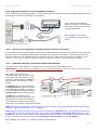
4.2.1.4 Installation with Cycle Analyst Molded External Shunt Module (Normal Mode)
The Grin Tech CA Molded External Shunt provides a
1.0mOhm external shunt resistor and brings out
necessary CA shunt and power connections to a 6 pin
CA-DP-compatible connector. The unused CA-DP Spd
and ThO signals are brought out to a Breakout Cable
for custom handling. The rated capacity is 50A but
sanding the face flat and clamping the shunt to an
aluminum plate or other heatsink will allow higher
current.
The module 'Controller' and 'Battery' wires are
unterminated and can be permanently wired in place
or fitted with connectors compatible with the installed
controller and battery.
Connect the shunt as shown to
the left.
The green ThO wire from the
breakout cable provides the
controller throttle Sense signal.
Attach an appropriate mating
connector.
The yellow Spd wire from the
breakout cable can optionally be
tied to any motor hall wire
(between hall connector and
controller) as an alternative to
using a wheel pickup.
As shown in the top illustration, the shunt resistor is in the negative power path and carries primary controller power.
However, the heavy red positive leads are only a packaging consideration and a convenient means to pick up Vbatt+
for CA power and monitoring; they need not carry primary controller power.
For instance, if a key switch is desired, then Vbatt+ can bypass the shunt module and run directly to the controller.
The two controller 'ignition' leads carry Vbatt+ to the key/kill switches and back to the controller to power the +5v
regulator and logic. When a controller has a CA interface connector, this switched Vbatt+ is supplied to pin 1. In this
case with no controller CA interface connector, the switched Vbatt+ is picked off the key switch and is run to either of
the shunt module heavy gauge red power leads to instead supply pin 1 of the shunt module connector. The other
heavy red module lead need not be connected.
Note: A CA Adapter Module may
be stacked with the molded
External Shunt Module to provide
throttle and ebrake signals to the
controller (e.g. for regen braking).
In that case, the Adapter Module
throttle connector must be used in
lieu of the green breakout cable
wire (see ' 5.3 eBrakes').
Step Complete. Go to section
' 4.2.2 Mount Console and Wheel
Pickup'.
3.0p6-g
18/65
Endless-Sphere.com
Unofficial CA V3 User Guide
4.2.1.5 Installation with RC Electronic Speed Controller (Normal Mode)
Depending on whether the Electronic Speed Controller (ESC) uses 50A or less, wire the unit according to either:
• ' 4.2.1.3 Installation with High Current External Shunt (Normal Mode)' or
• ' 4.2.1.4 Installation with Cycle Analyst Molded External Shunt Module (Normal Mode)'.
In either case, also wire CA-DP(6) (ThrO) to the ESC Servo Pulse Input. This signal is available as the green wire on
the CA-SA Molded External Shunt breakout cable.
If the ESC has no on-board BEC (Battery Eliminator Circuit), then the yellow CA-DP(5) connection for SP input can be
re-purposed to utilize the CA 5v supply as the BEC.
1.
On the controller end, tie CA-DP(5) to the ESC BEC input.
This connection is available on the CA-SA molded shunt breakout cable as the yellow wire.
2.
On the CA end, tie the yellow CA-DP wire to either the Throttle or AUX Pot 5v PCB pads. If working with a CADP instead of CA-DPS, it will be necessary to first unsolder the yellow wire from the CA PCB SP pad under the
brown square polyfuse.
CA-DPS Wiring to Supply 5v to RC ESC without BEC
Step Complete. Go to section ' 4.2.2 Mount Console and Wheel Pickup'.
4.2.1.6 Installation with Multiple Controllers (2WD)
A single Cycle Analyst CA-DPS can be used in multiple controller installations by supplying power to both controllers
using a single external shunt. Follow the Cycle Analyst installation instructions for the appropriate type of external
shunt and simply parallel the controller power, 'ignition' wires, and throttle connectors. If both wheel-motorcontrollers are identical then it can reasonably be assumed that each drive will use half the monitored/controlled
current so maximum current/power can be configured accordingly. Operation of the single throttle allows the CA to
give coordinated power to both drives using any of the available CA throttle modes (e.g. PassThru, Current, etc).
Switching between one and two motor operation requires special attention to accommodate different current/power
limits and can be accomplished with the AuxPot input. Installations with differing drives (wheel size, controller, or
motors) are more problematic and are beyond the scope of this manual.
Step Complete. Go to section ' 4.2.2 Mount Console and Wheel Pickup'.
3.0p6-g
19/65
Endless-Sphere.com
Unofficial CA V3 User Guide
4.2.2 Mount Console and Wheel Pickup
1.
Mount the Cycle Analyst Console
The Cycle Analyst display console comes with a mounting bracket for installation
on the handlebar. This bracket can rotate in two axes to adjust the display
position and fits 22 to 36mm bars. Use the provided rubber shims around the
tube if the clamp diameter is too large and fails to hold securely.
Note: The standard clamping thumbscrew may be replaced with the optional
security screw available separately from Grin Tech.
2.
Mount the Optional Wheel Pickup
Attach the pickup sensor to the fork using the two provided cable
ties and attach the magnet to a spoke using the screw in the
magnet body. Moving down the fork towards the hub will bring
these two components closer together. The magnet and pickup
sensor MUST be aligned as follows:
1.
position the pickup sensor so that it is aligned
perpendicular to the travel direction of the magnet
(i.e. aligned with the radius of the wheel). Because of fork
design this may not be exactly in line with the fork.
2.
position the magnet so that it is aligned with the groove
around the body of the pickup
3.
position the magnet and pickup sensor no more than
6mm apart - the closer the better
The sensor may be used with wheels lacking spokes (scooters, etc) by custom mounting to accommodate the
required alignment/clearance and gluing one or more rare earth Neodymium magnets to the wheel.
Note: Multiple spoke magnets may be installed to improve low speed responsiveness when using closed-loop
'speed throttle' (see ' 5.2 Closed-Loop Throttle Modes'). They need not be placed exactly evenly.
Note: Spurious power cutouts due to speed limiting or very large recorded maximum speed (see MaxS status
display) can arise from contact bounce in the sensor. Simple repositioning may remedy this problem, but
failed sensors with this issue require replacement – contact Grin Tech. A temporary remedy until replacement
is available is to defeat speed sensing by relocating the pickup so it cannot be triggered by the magnet(s).
4.2.3 Connect Throttle
Any device that can provide a voltage in the range 0-5v can serve as a Cycle Analyst throttle. Hall throttles typically
provide outputs of 1v to 4v while resistive throttles (e.g. Magura, 'pot box') typically provide outputs of 0v – 5v; any
of these are acceptable.
Follow either of the two following steps according to throttle type:
1.
Hall Throttles
The section ' 4.2.1 Connect Cycle Analyst to Controller' showed the proper point to connect the throttle for
each of the installation situations. If this has not yet been done, connect the throttle.
3.0p6-g
20/65
Endless-Sphere.com
2.
Unofficial CA V3 User Guide
Resistive Throttles
Loss of the throttle Gnd connection generally causes throttle output to swing to the rail voltage (+5v)
resulting in a Wide Open Throttle (WOT) runaway. The Cycle Analyst and some controllers can prevent such
runaways by detecting an 'input fault voltage' when the throttle voltage exceeds a certain limit somewhat
above the normal throttle maximum output.
Resistive throttles present a problem in that the maximum output is the +5v rail voltage making it impossible
to discriminate a fault condition.
A simple workaround is to introduce a resistor as shown to slightly
reduce the actual max throttle voltage. Loss of the Gnd connection
will still raise the Thi input to approximately 5v. Setup parameters
are adjusted for the slightly reduced working range so normal
throttle operation is unaffected.
Select a resistor to yield a 0.5v – 1.0v drop. For instance, with a
nominal Magura resistance of 5K, a 470 ohm to 1K resistor is
suitable.
The standard Cycle Analyst connector cable 'tree' shares a +5v connection for both Throttle and AuxPot
connectors. This makes addition of the resistor inside the CA case problematic if an AuxPot switch draws
varying amounts of current depending on setting – these current changes will upset throttle settings. The
resistor is best added to the throttle proper, in-line in the throttle cable, or within the CA case with a revised
CA throttle cable/connector that does not share wiring the AuxPot connector. In the latter case the resistor
can be soldered directly in-line with the (+5v) lead of the throttle cable within the case and then entirely
sleeved with heat shrink.
The section ' 4.2.1 Connect Cycle Analyst to Controller' showed the proper point to connect the throttle for
each of the installation situations. Connect the throttle as indicated.
IMPORTANT: If upgrading a previous V3 legacy installation, set ThrI->CntrlMode = PassThru before applying
power otherwise the existing setting of off (WOT) will apply WOT when the bike is powered ON.
Note: If in later steps the controller does not respond even though the V3 applies a proper throttle voltage (as
measured at the controller throttle input pin), then the controller may employ a 'missing throttle' safety circuit. Such
circuits block operation if the throttle is unplugged as determined by the absence of current at the throttle connector
power pins. If this symptom presents, simulate the presence of a throttle by adding a 1K resistor across the
controller throttle +5v/Gnd leads. This can may be conveniently done on the pins of the mating throttle connector
carrying the green CA-DP ThO wire. This resistor is harmless although unnecessary for controllers lacking a safety
circuit.
4.3
1.
Determine and Save Device-Specific Settings
Enter Setup and record the value of Cal->VScale which calibrates voltage measurements.
Do not lose this setting value.
IMPORTANT: This is a specific calibration for your particular CA and is set by Grin Tech during production.
2.
Determine and save the value to be used for Cal->RShunt which calibrates current measurements.
This is one of:
• 1 mOhm if using a new CA molded external shunt
• the shunt value of your specific controller
• the specific shunt value of your old V2 wired-in external shunt (value was saved above)
• the value of some other custom or high power external shunt
If the shunt value is unknown, see 'Appendix A. Calibrating the Cycle Analyst RShunt Value' for a default
value. After the CA is operational, use one of the procedures there to determine the proper value.
3.0p6-g
21/65
Endless-Sphere.com
4.4
Unofficial CA V3 User Guide
Update CA with Most Recent Firmware
1.
If the CA splash screen does not show the most recent version then download both the most recent firmware
and uploader application from the Grin Tech V3 web page. As a matter of policy, using the most recently
available uploader will ensure full feature functionality and will eliminate firmware installation difficulties.
2.
Flash the new firmware as described on the Grin Tech site. The
necessary programming cable (CA3-USB) is currently provided
with the V3 but see ' 5.10 Serial Data Port' if a replacement cable
is required.
During the flash procedure the Cycle Analyst will enter bootloader
mode and will display the screen to the right. The unit will reboot
and display the splash screen when re-flash completes successfully.
Note: Most settings in the Calibration section are preserved during re-flash, however, flashing erases all other
'settings. When performing subsequent firmware updates, first record all non-Calibration settings so that they
may be restored when the re-flash is complete. Setup Parameter documents located in this post contain a
printable form to assist in this manual save procedure.
4.5
Calibrate Current and Voltage Measurements (Make Device-Specific Settings)
1.
Configure Current Range, Voltage Scaling, and Shunt
Important: The V3 can operate in either of two modes to support vehicles drawing a maximum of
99.9 Amps (Cal->Range=Lo) or 999 Amps (Cal->Range=Hi).
Cal->Range differs from other Setup parameters and should not to be changed once the unit is configured.
Altering Cal->Range can have unforeseen effects on previously configured settings and associated Setup
entry screens. If configuration entry difficulties arise due to such alterations, re-flashing may be necessary.
a.
b.
If (Controller Maximum Amps) < 100A AND
(CA Shunt Resistance) >= 0.763 mOhm
1.
Set Cal->Range = Lo (W)
2.
Set Cal->VScale and Cal->RShunt as determined above
3.
The flashed PLim->AGain and PLim->WGain values provide suitable defaults.
(e.g. for v3B22 (AGain,WGain) = (150, 050) )
If (Controller Maximum Amps) >= 100A OR
(CA Shunt Resistance) < 0.763 mOhm
1.
Set Cal->Range=Hi (kW)
2.
Set Cal->VScale and Cal->RShunt as determined above
3.
Scale up the default values of PLim->AGain and PLim->WGain by 10x or set to 999 if the scaled
value is 1000 or greater (e.g. for v3B22 revise (AGain,WGain) = (999, 500) )
Important: The value of Cal->Range is not preserved when flashing and is instead reset to Lo. If you
are using the Hi setting and flash, always reset Cal->Range = Hi immediately after flash prior to altering
any other configuration items. This will ensure that other preserved calibration values are properly
interpreted and that entry fields are correctly displayed.
2.
Verify Zero Current Calibration
With ZERO throttle the CA should show a power reading in the neighborhood of 0-5W due to the controller
idle current. If you have large readings, the shunt voltage offset may need correction. Enter Setup and
navigate to the Calibration section, select Cal->ZeroAmps, and press-hold the right button. This will
re-calibrate the present current as 0.0 Amps.
If you have an external shunt or other custom wiring such that the CA obtains power independently of the
controller, then zero calibration is best done with the controller main power or 'ignition wire' disconnected.
This gives a 'true' zero current reading so that the CA will log a small battery drain due to the idle current
when the controller is ON but at zero throttle.
3.0p6-g
22/65
Endless-Sphere.com
4.6
Unofficial CA V3 User Guide
Configure Setup Parameters
4.6.1 Set Up Baseline Configuration
Only a few non-default parameters are required for basic operation; enter Setup and configure only the following
items - leave all others at defaults. Other necessary settings are addressed below - do not enable or configure more
advanced features until all setup steps in this section (' 4.0 Basic Installation (Install/Connect CA and Tune Throttle)')
are successfully completed.
(unless otherwise noted, the following values are only illustrative and should be
adjusted for your bike)
[...] = numeric entry field
{ ... | ... } = menu chooser
1.SETUP SPDOMETER
1. Spd -> Units
= { mi | km }
2. Spd -> Circumf = [2150] mm
3. Spd -> #Poles = [1]
(see 6.11 Determining Tire Circumference)
(number of motor poles or spoke magnets)
2.SETUP PRESETS
1. PrSt -> Preset Cnt = { Only1 }
- (leave at one preset for simplicity)
2. PrSt -> Batteries? = { Batt A Only } - (leave at one pack for simplicity)
3. SETUP BATTERY
1.Batt ->
2.Batt ->
3.Batt ->
4.Batt ->
5.Batt ->
A = { [A] }
Chemistry =
String#
=
Capacity
=
Vlt Cutoff =
{ LiFe | SLA | NiMH | LiMn | LiPo }
[20] Cells
[20] Ah
[50.0] Volts
4.SETUP THROT OUT
1.ThrO -> Output Mode = { Voltage | R/C Pulse }
5.SETUP POWER LIMS
1.PLim -> Max Current = [99.0] Amps
– (set to controller max rating)
To avoid unwanted interactions with other CA functionality, leave all other CA options in the default Disabled state.
1.
2.
3.
4.
PAS->PASMode
Trq->SensrType
Temp->Sensor
Aux->AuxFunct
=
=
=
=
Off
Disbld
Disabled
Off
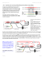
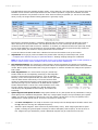
4.6.2 Set Throttle Input/Output Voltages
The goal of these voltage level adjustments is to match the output of the operator throttle with the controller throttle
input as illustrated below. This tuning
• minimizes throttle dead zones,
• ensures that wide open throttle (WOT) achieves maximum controller output, and
• ensures that the controller is completely shut down at zero throttle.
These are one-time adjustments and once made should never require alteration. Throttle voltage adjustments are not
designed to adjust controller power, although misadjustment can reduce power.
3.0p6-g
23/65
Endless-Sphere.com
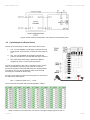
Unofficial CA V3 User Guide
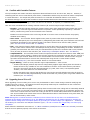
Voltage Range Mapping - Operator Throttle Output (ThrI) to Controller Input (ThrO)
The left figure above illustrates how the CA parameters are set near but not exactly equal to the related
throttle/controller values to ensure effectiveness in case of small mechanical and electrical variations with time and
temperature. For instance, ThrI->MaxInput and ThrO->MaxOut are adjusted so the CA detects max operator
throttle slightly before true WOT and accordingly delivers a bit more than the required maximum controller input.
Applying ebrakes always remaps any input voltage to ThrO->BrakeOut (normally 0.0v).
The right figure above illustrates the mapping of out-of-range inputs which can be caused by broken throttle
connections. As in the left figure, ebrake application supersedes these mappings but is not shown for clarity.
• Breaks in the throttle Sense or 5v+ connections send Throttle IN to 0.0v which the CA maps to
ThrO->MinOut.
• Breaks in the throttle Gnd connection drive Throttle IN to 5v, a dangerous failure. The CA prevents WOT
runaway by mapping voltages of ThrI->FaultVolt and above to ThrO->MinOut.
The following steps should ensure a near optimal configuration without guesswork - there are just a few steps and no
foreknowledge of the throttle or controller are required. Please postpone alterations to these recommended settings
until the entire throttle adjustment procedure is complete and fully operational.
Note: The following adjustments are best undertaken with the bike on a stand so the motor can be run to speed
safely. Use care in making these adjustments since high motor speeds may accidentally occur during the adjustment
process.
1.
EITHER – for 'Normal' Operation (CA Provides Throttle)
a.
Set ThrI->CntrlMode = Pass-thru
b.
Jot down the default settings for ThrO->UpRate, ThrO->DownRate , and ThrO->FastRate.
To avoid delayed response during adjustment, set these parameters to 99.99 V/Sec.
c.
3.0p6-g
Tune Thrl->MinInput and Thrl->MaxInput to match the actual throttle voltage range.
1.
Use the live Throttle In voltage display on the bottom of
the Setup Throt In screen to determine the voltages at
ZERO throttle and WOT.
2.
Transfer these readings to Thrl->MinInput and
Thrl->MaxInput but increase/decrease the Min/Max
settings respectively by 0.10V over the actual readings
to ensure full throttle range e.g. if read
(min,max) = (1.1, 3.9) then set instead to (1.2, 3.8)
24/65
Endless-Sphere.com
d.
Unofficial CA V3 User Guide
Set Thrl->FaultVolt auto-shutdown feature for damaged throttle connection.
Set Thrl->FaultVolt about half way between 4.99v and the actual measured max Throttle IN
e.g. for the example above (4.99+3.93)/2 ~= 4.5v.
e.
Adjust ThrO->MinOut and ThrO->MaxOut to match the controller min/max throttle input voltage range.
Note: The basic setup procedure outlined in this step is applicable to RC ESC installations although the
units are in msec instead of volts and the initial min/max range may be ESC-specific.
1.
Start by setting ThrO->MinOut,MaxOut to 0.00V and
4.99V respectively.
2.
Use the Diagnostic Screen (left button once from Main
Display) that shows Throttle OUT. While increasing the
throttle, note the OUT voltages at which the wheel
begins to turn (min) and stops turning faster (max).
3.
Verify the max setting does not cause the controller to
shut down from an input voltage fault. Slowly ramp the
throttle up until the controller shuts down from throttle
over-voltage fault; note the OUT voltage when this
occurs and in the next steps ensure that ThrO->MaxOut
is at least 0.25V less than this value.
Disregard this test if the controller does not shut down (it may lack this feature).
4.
Transfer the min/max readings to ThrO->MinOut and ThrO->MaxOut but decrease/increase the
settings respectively by 0.10V over the actual readings to ensure the controller is shut off at zero
throttle and actually reaches WOT e.g. if read (min,max) = (1.4, 3.9) then set to (1.3, 4.0) instead.
5.
If necessary, fine tune the ThrO settings so there is very small 'dead zone' at zero throttle and WOT.
Verify 'dead zones' by watching Watts on Main Display while moving throttle near/at zero and WOT Watts will not change in dead zones.
f.
2.
Restore ThrO->UpRate, ThrO->DownRate, and ThrO->FastRate to the default settings recorded earlier.
OR – for 'Legacy' Operation (CA Limits Operator Throttle)
a.
Set ThrI->CntrlMode=Off (WOT)
b.
In legacy mode, ThrI->MinInput and ThrI->MaxInput have no effect; these parameters may be left at
the default settings.
c.
In legacy mode, ThrO->MinOut and ThrO->MaxOut are equivalent to the CA v2.x parameters ITermMin
and ITermMax respectively. To paraphrase sections 8.11 and 8.12 of the CA v2.23 Manual:
“ThrO->MaxOut puts an upper limit on how high the throttle over-ride will drift upwards when none of
the limit values are being exceeded. Ideally this value is set to the voltage that is considered full
throttle by the controller. For hall effect throttles, full power occurs at about 4V, and limiting the ITerm
to this value will speed up the response time of the limiting features. Allowable values are from 0 to
4.99V.”
“ThrO->MinOut imposes a lower bound on how low the throttle over-ride can drift downwards when
one of the limiting values is being exceeded. By preventing the over-ride signal from going all the way
to 0V, you can decrease the recovery time for the signal to go back upwards. Range is from 0 to
4.99V, and must be less than ThrO->MaxOut.”
These values are ideally the controller throttle input voltages at which the motor just begins to turn
(actually a bit less), and stops turning faster at no-load (actually just a bit more). Unlike 'normal' mode,
there is means in legacy mode to measure and determine these settings using the CA alone. Unless you
have specific knowledge of the controller throttle input voltage range, leave these settings at the defaults
for the first try and adjust for more optimal limiting operation later if necessary.
3.0p6-g
25/65
Endless-Sphere.com
d.
4.7
Unofficial CA V3 User Guide
Use the Diagnostic Screen to verify that the Throttle OUT voltage is equal to the configured
ThrO->MaxOut. When underway, this value will fall towards ThrO->MinOut as any limiting parameter
comes into play.
Test Throttle and Limit Settings (Interpreting Limit Flags)
Your CA is now ready for a test ride where one or more of the limit parameters may affect the throttle output voltage.
1.
Verify Throttle Adjustments:
• Verify that at zero throttle there is no pronounced dead zone and no motor creep.
Otherwise, revisit the ThrI->MinInput and ThrO->MinOut adjustments above.
• Verify that at WOT there is no pronounced dead zone and that the bike delivers maximum power.
Otherwise, revisit the ThrI->MaxInput and ThrO->MaxOut adjustments above.
Note: The recommended 0.10v throttle adjustment offsets may be reduced to minimize throttle dead zones,
but motor creep, maximum power reduction, or auto-cruise/PAS problems may arise. Reducing the offsets is
not recommended, but if undertaken, should be accompanied with a policy of regular throttle setting
verification.
Persistent auto-cruise or PAS dropouts may be remedied by increasing the ThrI->MinInput offset to 0.15v.
2.
Verify Limit Configuration
If the throttle is correctly adjusted and the bike still fails to achieve full power, then some Limiting Parameter
may be unexpectedly coming into play. Use the 'Limit Flags' display on the Diagnostic Screen to identify any
limits in effect (see table below). Upper case flag characters indicate which Limiting Parameter is presently
moderating throttle output and so may require adjustment. Gain Parameters are discussed in the next
section.
Note that the speed limit flag is only asserted if you actually exceed the limit. There are other aspects of the
speed control logic that can lead to limiting or speed oscillations (next section) but that are difficult to
evaluate as causing a problem. As a result, there can be a speed-related issue with no 'S' Limit Flag.
Legacy mode only:
In legacy mode, limiting is in effect whenever Throttle OUT (plus a diode drop) is a lower voltage than
that of the operator throttle. If the bike does not achieve full power, the value of ThrO->MaxOut may be
set too low causing limiting to accidentally be in effect in spite of Limit Flag indications.
• Temporarily adjust ThrO->MaxOut = 4.99. If this remedies the problem, then take throttle voltage
measurements to more accurately determine the minimum voltage necessary to achieve maximum
unloaded motor speed at WOT.
• Alternatively, reset ThrO->MaxOut to the default then iteratively increase the value by 0.1v and test
until no further WOT speed improvement occurs.
3.0p6-g
26/65
Endless-Sphere.com
Unofficial CA V3 User Guide
Adjust Throttle Ramping
4.8
Throttle ramping is not available in legacy mode.
Note: Ramping adjustments in this section and gain adjustments in the next section may interact so some iteration
may be required. Adjustment may be unnecessary for many low to moderate powered builds, but review of these
sections will assist in recognizing and addressing less than optimal performance.
Throttle ramping affects Throttle OUT universally and so plays a role in operator throttle, closed-loop throttle, PAS,
auto-cruise, etc. The ramping logic appears as a clamping mechanism to moderate the rate of throttle change and
only participates when the the rate of Throttle OUT change exceeds configured limits – at lower rates it has no effect.
Ramping can have an effect on the stability of controller current and speed limiting logic for certain vehicles. It may
be best to configure ramping as close as possible to final desired values according to personal preference before gain
adjustments are undertaken. This policy allows conservative ramping adjustments to be made later with little
likelihood of stability impact. This is not strictly necessary, but may prove a useful policy.
Adjust ThrO->DownRate, ThrO->UpRate, ThrO->FastRate, and ThrO->FastThrsh as appropriate to achieve the
desired throttle response. All ramp settings are in V/sec so smaller values yield longer ramp times.
• DownRate is a limit controlling the maximum rate at which power can be reduced. Slower DownRate can be
beneficial for PAS or certain drive systems, otherwise a rapid rate may be desirable to give brisk throttle response.
Ebrake application immediately suppresses DownRate (see ' 5.3 eBrakes') so DownRate tuning need only consider
throttle responsiveness (not braking).
•
UpRate is a limit controlling the maximum rate at which power can be applied. This can be used to slow
power application giving smoother getaways without harsh acceleration. Gear motors, mid-drives, and
powerful DD motors may benefit from smaller values to moderate power on dead starts.
•
FastRate is similar to UpRate and is typically set to a faster rate.
•
FastThrsh sets the FastRate to UpRate switchover current.
• If FastThrsh = 0.00A, FastRate is ignored and UpRate is always employed, otherwise:
• When current is less than FastThrsh, the CA uses FastRate to allow the motor to quickly come to speed.
This is useful for gear motors or mid-drives when re-engaging a freewheel if already underway.
• When current is FastThrsh or greater, the CA uses UpRate – typically to apply slower ramping.
UpRate and DownRate are preset-specific; FastRate and FastThrsh are common across presets.
The approximate ramp time for a full throttle excursion (ZERO to WOT or WOT to ZERO) is determined by:
ramp time = (ThrO->MaxOut – ThrO->MinOut) * (ThrO->xxxRate)
Examples:
• The fastest down-ramp time can be achieved by using the largest allowable DownRate (99.99V/sec) and
might yield a typical delay of (3.9v – 0.8v) / (99.99V/sec) = 0.031 sec (essentially undetectable)
• To get a 2.5 second up-ramp time for a gear motor, UpRate might be (3.9v – 0.8v)/2.5sec = 1.25V/sec
4.9
Adjust Gain: Minimize Surging or Speed Oscillations
Control overshoot and power oscillations may occur whenever the Cycle Analyst provides current, power, or speed
limiting. Alternate closed-loop throttle modes (e.g. Current Throttle) where the throttle sets the limit so limiting is
always in effect are just special cases of classic 'maximum value limiting' (e.g. MaxCurrent).
The Cycle Analyst utilizes PI (proportional-integral) and PID (proportional-integral-derivative) controllers for
current/power and speed limiting respectively. The behavior of this controller logic is determined by gain settings that
affect the degree of feedback from measurements of battery voltage, shunt current, and speed. These gain settings
allow the Cycle Analyst to be tuned for proper operation across a wide range of vehicle powers and weights. Although
the default gain settings will prove suitable for many low to moderate powered builds, some vehicles will require
additional adjustment (e.g. those with high power to weight ratios).
3.0p6-g
27/65
Endless-Sphere.com
Unofficial CA V3 User Guide
Throttle correction is controlled by the gain setting of whichever Limiting Parameter is in play (see 'Limit Flags'). For
example, if PLim->MaxAmps forces limiting then PLim->AGain will control throttle correction. If power oscillation is
present, inspect the 'Limit Flag' display on the Diagnostic Screen while surging is underway. Limit Flag(s) that change
state in synchronization with the surging indicate the gain settings of interest.
Speed, current, and power gain settings are global parameters and are common across all presets.
Legacy mode only:
In legacy mode, slow limiting correction can also occur if ThrO->MinOut or ThrO->MaxOut are set far from
the desired values described earlier (i.e. default settings may work, but suboptimally). This can cause
correction delays as the CA limiting voltage takes time to change across the 'dead zone' between the actual
and optimal settings. This symptom can be identified by examining the Throttle OUT voltage on the Diagnostic
Screen and watching if there is substantial OUT change with no apparent effect on bike power - followed by
the delayed/desired correction. If necessary, adjust the ThrO parameters as described above.
4.9.1 Current and Power Gain (AGain, WGain)
These gains participate whenever current or power limiting are in play and in particular during operation of PAS and
Current or Power Throttle. Reducing the related gain setting minimizes overshoot and dampens oscillation, while
excessive reduction leads to sluggish response. Adjustment is straightforward.
Here are specific recommendations for each gain setting:
Grin Tech V3 web page:
AGain: Feedback gain for the current control loop. Generally it should be increased until you start to feel the current
limit being rough or oscillating, and then scaled back about 30%.
WGain: Same story as A Gain above, only now applied to the power limiting feedback loop.
It may also be worth a small gain adjustment if the bike appears to ride smoothly but the Amp/Watt displays fluctuate
widely around the limit setting - over/under fluctuations should be modest and easily tracked by eye.
4.9.2 Speed Gain (PSGain, IntSGain, DSGain)
These gains participate whenever speed limiting is in play and in particular during operation of Speed Throttle.
Here is a summary of the three speed-related gain adjustments:
Grin Tech V3 web page:
IntSGain: Integral feedback gain for speed PID control loop. Lower values give smoother control and less likelihood of
hunting, but can increase the time it takes for the speed limit to stabilize.
PSGain: Proportional feedback term for speed control loop. Displayed in terms of Volts / (mph or kph). So if it is set
to 0.5V/kph, then for each km/hr you go above the speed limit, the throttle output will immediately drop by 0.5V.
DSGain: Differential feedback term for speed control loop. This is used to dampen oscillations from speed limiting.
Because the speed PID controller tries to anticipate limiting situations before they occur, some vehicles may
experience cutouts during hard acceleration. The problem arises as the vehicle rapidly accelerates toward the speed
limit and the Cycle Analyst preemptively reduces the throttle to avoid overshoot – even though the limit has not yet
been reached. This cutout symptom is an indication that the DSGain setting is too high (too much 'future sense'). The
CA cannot actually discern that meaningful limiting is in effect and so the associated 'S' limit flag gives no indication.
The more complex PID controller employed for speed limiting is of a type that classically presents a greater
adjustment challenge. If speed-related surging or power cutouts occur, apply one of these two remedies:
1.
If Speed Throttle or enforcement of SLim->MaxSpeed are desired, please follow the tuning procedure for the
speed controller outlined in 'Appendix D. Tuning Speed Control Gain Parameters'.
2.
If Speed Throttle and maximum speed limit enforcement are not required, disable the speed control logic:
set SLim->MaxSpeed to the maximum value, IntSGain = 100, PSGain = 0, DSGain = 0.
3.0p6-g
28/65
Endless-Sphere.com
5.0
Unofficial CA V3 User Guide
Advanced Features
Features in this section may be enabled once basic setup is complete. Some of the features may interact in
unexpected ways and configuring/tuning them one by one is recommended. The CA3 Setup Utility may be used to
preserve intermediate configurations as 'restore points' until the entire desired feature suite is fully operational.
5.1
1.
Battery Low Voltage Cutoff (LoVGain)
Overview: If in non-legacy mode, the The Cycle Analyst provides low voltage cutoff (LVC) that reduces
power (throttle) until the LVC condition is alleviated or until power is removed completely. All batteries exhibit
some internal resistance that causes voltage sag under load as the current impressed across the resistance
develops the small 'sag' voltage. Reducing the throttle reduces the current drawn by the motor and has a side
effect of causing the battery voltage to rise – possibly eliminating the LVC condition. The V3 attempts to
'feather' the throttle to reduce voltage sag and so remove the LVC condition. Severe LVC situations that
reflect a true low state of charge, not simple sag, are remedied by rolling the throttle back completely.
LVC functionality is implemented as a PI (Proportional Integration) controller similar to the controllers that
implement other limiting functions such as speed and power. When the LVC limit is exceeded, the CA begins
correcting (reducing) the throttle in an attempt to remove the LVC condition. The gain setting determines the
magnitude of the corrections and so, indirectly, the rate at which the condition is alleviated.
2.
Adjustment: LVC is individually configured for each of the available battery presets. Switching presets applies
the LVC configuration appropriate for the associated battery. For each battery preset:
• Batt->VltCutoff is the simple limiting voltage
• Batt->LoVGain is a dimensionless gain setting. Large values cause larger corrections and more rapid
action, smaller values have the opposite effect, slowing the power roll-off. Specifically, lower values will
allow brief excursion of the battery voltage below the LVC on acceleration with no immediate power
reduction so cutouts are avoided while reaching cruising speed and lower current draw/voltage sag.
5.2
Closed-Loop Throttle Modes
1.
Overview: If in non-legacy mode, the CA offers three additional
closed-loop throttle modes that can give substantially improved
throttle control:
• Current Throttle
• Power Throttle
• Speed Throttle
These are 'fly by wire' modes where the operator throttle is not passed through to the controller but rather
sets 0-100% of the associated limit parameter as a target for the CA to achieve. The CA alone supplies the
controller throttle and receives feedback from the shunt or speed sensor to determine how well it has done in
achieving that target. It then adjusts the controller throttle in a closed loop to cause the output to track the
desired rider throttle input. The CA will maintain the target limit regardless of changes in terrain.
In this mode any unpleasant nonlinearities in the controller-motor
curves are of little consequence as
adjustments to achieve the desired
output are exclusively the
responsibility of the CA, not the
rider.
For example, in the case
of Current Throttle, if
PLim->MaxCurrent is set to 50A
then WOT is 50A. Assuming the
rider throttle is more or less linear,
adjusting the throttle to 10%
rotation yields a predictable
controller output of 10% of 50A or 5A.
3.0p6-g
29/65
Endless-Sphere.com
Unofficial CA V3 User Guide
The table below shows the available throttle modes - all but Pass-thru are closed loop. The columns show the
feedback source and the relevant parameters for each mode of operation. To get the smoothest and most
consistent operation it may be best to set the 'other' limits as loosely as possible (i.e. set as true max safety
limits) so only the single throttle limiting parameter is generally in play. Throttle Mode Summary
Note that the CA Speed Throttle is completely different than the Infineon controller throttle logic which is
often referred to as a 'speed throttle'. The CA Speed Throttle is a true closed loop control system that
measures the bike speed and corrects for variations. In contrast, the Infineon throttle uses open loop control
to vary phase PWM duty cycle according to the input throttle voltage without regard for directly measured
bike or motor speed; this results in varying speed with load and terrain.
Current and Power Throttle modes have a familiar feel and are the easiest to set up and control.
2.
Adjustment: If surging or power oscillations are present after selecting a closed-loop mode, revisit
' 4.9 Adjust Gain: Minimize Surging or Speed Oscillations'. Existing ramping settings are unaffected.
Note: It may be useful to use a new preset when tuning a new closed-loop throttle mode so that operation in
PassThru mode remains readily available until the new mode operates satisfactorily.
3.
Hall Throttle Linearity: The closed-loop control strategy cannot compensate for throttle non-linearities.
Many hall-effect throttles are intrinsically non-linear and so will compromise the effectiveness of these throttle
modes. Better quality hall throttles with a long linear magnet or resistive throttles like a Magura will yield the
best results.
4.
Limit Flag Behavior: It is normal when using any closed-loop
throttle mode for the corresponding Limit Flag on the Diagnostic
Screen to show almost continuous limiting - even at standstill.
Similarly, in the case of Speed Throttle, the main screen 'kph/mph'
units will flash almost continuously. This occurs because these
modes are implemented using the normal limiting logic except that
internally the logic input is assumed to be WOT and the operator
throttle instead scales 0-100% of the Limit Parameter. As a result,
the CA is always trying to go WOT but is almost always being
restrained by the adjustable throttle limiting. This asserts the
Limit Flag.
5.
Spoke Magnets and Speed Throttle: Using Speed Throttle at very low speeds can be problematic if using a
wheel pickup in the standard configuration. With only a single spoke magnet, the Cycle Analyst gets a speed
update only once per revolution or about once every two meters. Off the line or at very low speeds, this is
inadequate for smooth speed control. There are two means to remedy this:
3.0p6-g
a.
Set SLim->StrtSpeed to 5 or 6mph so that the Cycle Analyst will not attempt Speed Throttle control until
the Sp pulses are arriving with adequate frequency.
b.
Add more spoke magnets. These need not be placed exactly evenly. Each magnet generates a speed
update, reducing the ground speed necessary to achieve adequate pulse frequency. As few as three or
four magnets will give satisfactory results. Additional magnets may be ordered from Grin Tech.
30/65
Endless-Sphere.com
5.3
Unofficial CA V3 User Guide
eBrakes
1.
Grin Tech:
“This input has an on-board pull-up to 5V to be used with an ebrake cutoff switch. When the signal is shorted
to ground, the CA thinks that your brake levers are depressed and forces the CA's throttle output to 0V.“
2.
Operation: The Cycle Analyst EBK input is asserted when low. This causes ThO to be driven to
ThrO->BrakeOut which is nominally 0.00v; no other operation reduces ThO lower than ThrO->MinOut
making it possible for an external circuit (e.g. CA Adapter Module) to examine the ThO level to discriminate
between throttle ZERO and ebrake application.
PWM output is affected similarly when ThrO->OutptMode=R/CPulse. Some ESCs fault when the pulse
width goes to zero so in those cases ThrO->BrakeOut can be set to a low non-zero value that is compatible
with the particular ESC.
• Ebrake application suppresses ThrO->DownRate so Throttle OUT changes are affected immediately.
IMPORTANT: Setting ThrO->BrakeOut higher than ThrO->MinOut causes EBK assertion to apply
non-ZERO throttle. Use care in configuring this value.
• Ebrake application causes auto-cruise to disengage (See ' 5.4 Auto-Cruise Control').
IMPORTANT: Do not use the auto-cruise feature unless ebrakes are installed and wired to the Cycle
Analyst EBK input. Using auto-cruise with the conventional ebrakes connection to the controller can
cause a dangerous runaway situation as soon as the brakes are released since auto-cruise will not be
disengaged.
• Ebrake application causes PAS assist to cease immediately (See ' 5.6 Pedal Assist').
IMPORTANT: Depending on the installation and CA configuration, some PAS power overrun may occur
when pedaling ceases. Unsafe stopping situations may arise if ebrakes are not wired to the Cycle Analyst
EBK input. Although such situations are seldom an issue for low powered PAS installations, use of
ebrakes with CA PAS is recommended.
3.
Live Data: When EBK is asserted, an animated eBrake graphic replaces the Throttle Gauge on the main
display (see 'Main Status screen').
4.
Electrical Characteristics: The EBK pad ties to a microprocessor port through a 1K resistor. The pull-up
current is approximately 150uA with an effective (min,typical,max) pull-up resistance of (15K,30K,200K). The
threshold voltages at the EBK pad are approximately 1.5V to activate and 2.1V to release. Either a mechanical
switch or hall effect device makes a suitable sensor.
5.
Device Connection: The Cycle Analyst Ebk input is compatible with common Normally Open (NO) ebrakes.
If ebrake application is only to provide simple throttle cutout, then ebrakes may be connected to the Cycle
Analyst using the connector illustrated above. This will work in either new or legacy modes. However, if any
controller feature is employed that relies on direct ebrake input (e.g. regen), then the ebrake connection must
be run to the controller instead of, or in addition to, the Cycle Analyst.
The figures on the following page illustrate three common connection scenarios:
3.0p6-g
31/65
Endless-Sphere.com
a.
Unofficial CA V3 User Guide
Case 1: Simple
throttle cutout is
provided by the CA
and no controller
features require
ebrake input.
Ebrakes are run only
to the CA.
3.0p6-g
b.
Case 2: Both CA and
controller features
require ebrake input.
The ebrake signal is
connected in parallel
to both the CA EBK
input and the
matching controller
ebrake input. A
separate wire may be
run or for a CA-DPS
model, the yellow Spd
wire of the CA-DP
cable may be repurposed to carry the
signal. The controller
ebrake connector Gnd
connection is
unnecessary.
c.
Case 3: Both CA and controller features require ebrake input. A CA Adapter Module on the CA-DP cable
recovers an equivalent ebrake signal from the ThO signal on CA-DP pin 6 (see: 'Install Using a CA
Adapter Module '). The module provides a throttle and ebrake connectors to directly drive the controller.
This solution works for both 'legacy V2' and 'Large Screen Compatible' controller interfaces.
32/65
Endless-Sphere.com
5.4
Unofficial CA V3 User Guide
Auto-Cruise Control
1.
Operation: Auto-cruise is a firmware-only feature that locks in the preset Throttle IN voltage until
disengaged. For example, Speed Throttle selects a speed between 0-100% of SLim->MaxSpeed and so will
maintain the 'set' Throttle IN speed regardless of terrain. This feature can be used with any throttle mode:
PassThru, Current, Power, or Speed.
Auto-cruise is enabled by setting ThrI->AutoCruis from Off to one
of several preset hold times. This is a preset-specific parameter
that determines the period of time that the operator throttle must
be held stationary to engage auto-cruise.
The ThrI->CruiseHld parameter determines the allowable (+,-)
voltage variation for the operator throttle in order for it be
considered 'held stationary' for the AutoCruis period.
When auto-cruise engages, a second blinking 'ghost' indicator
appears on the throttle bar graph at the 'set' cruise level. The
normal solid slider continues to move with the throttle. The
appearance of the blinking slider gives a visual indication that cruise
is engaged and the throttle can be released. The 'In' label on the
Diagnostic screen also blinks.
Auto-cruise disengages when ebrakes are applied or when the operator throttle is moved in the direction of
WOT regardless of its present position.
IMPORTANT: Do not use the auto-cruise feature unless ebrakes are installed and wired to the Cycle Analyst
EBK input. Using auto-cruise with the conventional ebrakes connection to the controller will not disengage
auto-cruise when brakes are applied and may cause a potentially dangerous runaway situation as soon as the
brakes are released.
2.
PAS Interaction: If ThrotPAS mode is enabled, pedaling must be detected for auto-cruise to apply throttle
control. When pedaling ceases, auto-cruise ceases to provide throttle but does not disengage – resuming
pedaling will cause auto-cruise to resume the engaged throttle setting. Auto-cruise can be used as a means
to provide an on-the-fly setting for PAS assist – see ' 6.10 Auto-Cruise as an Adjustable PAS Level'.
3.
PAS Dropouts: Sporadic dropouts in PAS operation may be traced to a ThI->MinInput voltage offset that is
too small. See ' 4.7 Test Throttle and Limit Settings (Interpreting Limit Flags)'.
4.
Conflict with Controller Cruise Control: The conventional controller cruise control operates by
supplying/controlling motor power in lieu of the throttle input. Depending on Cycle Analyst configuration, this
can have dangerous consequences as the Cycle Analyst attempts to correct speed or power utilization that is
actually outside its control. If cruise control operation is desired, always use the Cycle Analyst functionality
which will provide properly integrated throttle control.
IMPORTANT: Do not use controller-based cruise control when a Cycle Analyst is attached in any but the
most basic monitoring mode (e.g. only shunt and voltage connections) as potentially dangerous loss of
throttle control may result.
3.0p6-g
33/65
Endless-Sphere.com
5.5
Unofficial CA V3 User Guide
Auxiliary Pot
The AUX Pot JST-3 is white to differentiate it from the black Throttle JST-3
1.
Grin Tech:
“The purpose of this input is to allow on-the-fly adjustments of one of the CA's limit values
(i.e. the current limit, speed limit, or power limit). That can be accomplished either via a potentiometer, or for
discrete settings with a multi-position switch and resistor dividers. A 0-5V signal range is allowed, and it
defaults to 5V if left disconnected.”
2.
Live Data Display: The AUX Pot Setup preview screen provides a
live data display of the POT input which can be used to dial in
trimpots or inspect voltages as controlling switches/pots are
manipulated.
3.
Modes: The AUX Pot input can operate in either of two modes
determined by Aux->Function:
• Limit: The applied voltage scales a limiting parameter or
• Preset: The applied voltage selects one of the available mode presets.
a.
Limit Mode: This provides a means to apply an external control voltage (max range 0-5v) to provide a
0-100% scale of the limiting parameter specified by Aux->ScaleLim.
Aux->ScaleLim
Amps Lim
Power Lim
Speed Lim
PAS Level
POT input controls
0-100% of parameter
PLim -> Max Current
PLim -> Max Power
SLim -> Max Speed
PAS->PAS Watts ( if PAS->PAS Mode = Auto PAS )
Trq->Asst Factr ( if PAS->PAS Mode = Torq PAS )
Any device with a voltage output in the range of 0-5v may be used. Examples of external controls:
• Potentiometer: This is the most basic adjustment technique.
R1 = 5K linear taper pot. To prevent contaminants from entering
the device either use a 'sealed' type pot, enclose it completely, or
seal it using a product like Liquid Lectric Tape or Plasti-Dip.
• Throttle: A resistive or hall effect throttle may be substituted for
the potentiometer. For instance, a thumb throttle may be located
on the left side and be modified so that it stays in position when
adjusted.
3.0p6-g
34/65
Endless-Sphere.com
Unofficial CA V3 User Guide
• 3-Position Switch: This is the Cycle Analyst version of the conventional controller 3-position
switch. The example implementations below provide three settings: Low, Medium, and High.
The LMH version is better suited to rocker switches while the LHM version may be better suited to
toggles where the center (high) position is a little fussier to achieve.
R1 = R2 = 5K 20 turn trimpots, R3 = 7.5K, R4 = 10K.
Depending on the Aux->ScaleLim setting, these sample circuits may be used as a 0-100% PAS Assist
knob, a 0-100% speed limit knob, a 3-position current or power limit control, etc. The examples can be
combined. For instance, the illustration below shows the LMH switch above extended with an external 5K
linear pot (R5) on the 'high' setting. The pot serves double duty in different presets as either a PAS level
adjustment or when set to the high extreme, the 'High' setting of the LMH switch for throttle-based
non-PAS operation.
These particular sample circuits assume
Aux->MinAuxIn = 0.0v and
Aux->MaxAuxIn = 4.99v; other circuits
may have different requirements.
Devices like a hall throttle are best
configured based on voltage
measurements from the AUX Pot
Setup preview screen.
b.
Preset Mode: This provides on-the-fly preset selection using an external switch. The Cycle Analyst
selects a mode preset by dividing the voltage range between Aux->MinAuxIn and Aux->MaxAuxIn into
the same number of equally sized voltage bands as there are presets (1,2, or 3) and determining in
which band Vpot lies. Input voltages below/above the configured min/max range are considered to fall
within the adjacent lower/upper voltage band respectively. The highest voltage band is preset #1.
When a new preset is selected, a “CHNG MODE PRESET” screen is briefly displayed.
The left diagram above will select from two presets. The right diagram uses R1 = R2 = 4.7K resistors
and will select from three presets. These particular sample circuits assume Aux->MinAuxIn = 0.0v and
Aux->MaxAuxIn = 4.99v although other circuits might use a different range.
Note: The Grin Tech 3-Position Switch is available as a plug-and-play solution for either Limits or Presets
modes. Although this switch uses fixed resistors instead of trimpots, the selectable limit levels are
configurable using Setup. 'Appendix E. Configurable Aux Pot 3-Position Switch Using Fixed Resistors'
describes how to configure the Grin Tech switch as well as how to construct a similar DIY version.
3.0p6-g
35/65
Endless-Sphere.com
Unofficial CA V3 User Guide
4.
Electrical Characteristics: To avoid affecting external resistor dividers, the Aux POT input does not have
pull-up or pull-down resistors on the PCB although there is a weak pullup internal to the processor port. The
applied impedance should be no more than 10K for the A/D converter to achieve full 10bit accuracy, although
realistically, full 10 bit accuracy is unnecessary for these external switch applications.
5.
Throttle Scaling: Throttle scaling causes the throttle maximum to be limited by the POT input value instead
of the configured limiting parameter maximum. For example, if PLim->MaxCurrent=50A, POT (min,max) is
(0v,5v), and POT = 1.0v (20% of the 5v POT range), then Throttle OUT will be limited to 20% of 50A or 10A.
To obtain automatic throttle scaling, Aux->ScaleLim and ThrI->CntrlMode must be configured to use the
same limiting type. This may not always be possible, for instance when using Current Throttle and PAS Aux
Pot control, but mixed current and power limiting can be resolved to use one or the other limiting type
exclusively. For the example above to work as described, Aux->ScaleLim and ThrI->CntrlMode must be set
to matching values: AmpsLim and Current respectively. 'Matching' limiting type values are shown above in the
'Throttle Mode Summary' table.
The sample plots to the left show the
Cycle Analyst current limit vs 0-100%
throttle rotation for three different Aux
POT limit settings (20%, 70%, and
100%). In each case WOT is scaled to the
existing Aux POT limit and the throttle
output is linear with throttle rotation,
ZERO to WOT. This is a desirable behavior
for an Aux Pot control such as a LMH
switch.
In contrast, the plot to the right shows
an example where throttle and Aux POT have
differing limit parameters
(e.g. current and power). In this case there is
no throttle scaling; instead, the Aux POT limit
imposes a ceiling above which further throttle
rotation has no effect. This causes an operator
throttle 'dead zone' identical to that produced
by the simple limiting of legacy mode (V2)
operation. This behavior can be converted to
that shown above by simply adjusting
Aux->ScaleLim = AmpsLim.
3.0p6-g
36/65
Endless-Sphere.com
5.6
Unofficial CA V3 User Guide
Pedal Assist
1.
Grin Tech:
“10V: This is an output pad specifically for supplying power to the THUN torque sensing bottom bracket. It
can potentially be used as a low current power source by other PAS sensors too, however care must be taken
as this supply is not fused or protected, and a short to ground will damage the CA. Current draw from this
line should be limited to 15mA max and only with 48V or lower batteries.
Pedal Sensor Input (RPM): This is a digital input for a pedal cadence sensor. It has an onboard pull-up resistor,
so it can work with an active hall effect device or a simple magnet and reed switch pickup.
Pedal Direction Input (Dir): This is used to distinguish between forwards and reverse pedal rotation for PAS
sensors that provide this signal. It can support both a pure direction signal (e.g. 5V = fwd, 0V = reverse), or
a quadrature type encoder such as on the THUN sensors.
Torque Sensor (Trq): This is a 0-5V input for a torque signal. The human pedal torque can be measured either
via a torque sensing bottom bracket (THUN, FAG), or via a DIY tension meter on the bike chain itself. The
torque signal here is multiplied by the calculated pedal RPM signal to derive the human power on the CA, and
to provide proportional torque assist.”
2.
Supported Sensors: The PAS signal interface is primarily designed for the THUN torque sensing bottom
bracket but also supports similar units from TDCM, FAG from Germany, and Green Trans from Taiwan.
Alternatively, it can use a simple PAS cadence wheel providing a contact closure or 0v/5v pulse output. The
direction input can be a Fwd/Rev level or a pulse waveform providing quadrature encoding in concert with the
RPM signal. Grin Tech has custom PAS wheel sensors that are plug compatible with the CA-TRQ connector.
These units utilize novel mounting techniques so the crank/BB do not require disassembly.
Note: PAS wheel sensors must have a pulse output. Sensors providing a throttle-compatible analog voltage
output cannot be used. PAS wheels typically do not have a direction output to detect pedaling backwards
although some may instead only send pulses pedaling forward which is equally effective. See ' 6.2 DIY PAS
Sensor / Adding Direction Output to a PAS Wheel' for a means to add a second pickup to simple PAS wheels to
discriminate direction.
3.
Sensor Operational Overview: PAS cadence sensors are 'pedaling detectors' and provide a means to
activate a constant non-proportional power assist, that is, the assist is ON or OFF and constant regardless of
pedal RPM. PAS wheels are available with varying numbers of poles – typically 5 to 16. PAS wheels with many
magnets are preferred because the larger number of impulses mean pedaling is detected sooner and the PAS
system reaction is more responsive and natural.
Torque sensors provide the same 'pedaling detection' pulse signal as PAS cadence sensors but add an analog
torque signal that varies linearly with torque. In TorqPAS mode, the Cycle Analyst uses this variable torque
signal to provide proportional assist according to how hard the rider pedals. However, if the Cycle Analyst is
instead configured in AutoPAS or ThrotPAS modes (see below) then the torque signal is ignored and the
sensor operates as a simple PAS cadence sensor.
For PAS cadence sensors, assist is enabled only when the optional direction signal indicates 'Fwd'. For torque
sensors, the rider actually be pedaling to enable assist; simply standing on the pedals to generate a large
torque signal is ineffective.
3.0p6-g
37/65
Endless-Sphere.com
4.
Unofficial CA V3 User Guide
Sensor Power: The Thun, TDCM, and PAS wheel sensors from Grin Tech are plug and play compatible with
the CA V3 and no special action is required to obtain power.
Certain other PAS cadence sensors utilize hall sensors instead of reed switches. These sensors require a +5v
supply which may be obtained by various means:
• A +5v tap may be added to either mating JST connector for CA throttle or Aux POT.
• The white +10v power lead of the CA-TRQ/PAS connector may be re-purposed by relocating the
connection to either of the Throttle or POT +5v pads of the CA PCB.
• A +5v tap may be added to the mating JST connector for the controller throttle.
IMPORTANT: THUN Power Requirements: Please pay particular attention to the current limit of the CA
when powering any added sensor. Please choose an appropriate power strategy as described in ' 5.9 Cycle
Analyst as a Power Source' when adding any sensor or accessory to the CA.
5.
PAS Configuration:
a.
PAS->Plrty controls Fwd/Rev direction determination for both level (Dir) and quadrature (RPM+Dir)
signal types.
b.
PAS->PAS Mode options:
In all modes, if throttle is applied even a small amount while pedaling, PAS assist is ignored and the
throttle alone determines the output.
Set SLim->MaxSpeed to limit the maximum assisted speed. The throttle is enabled without pedaling at
speeds up to PAS->MxThrotSpd, while at higher speeds pedaling is required to enable the throttle; set
PAS->MxThrotSpd to zero to always require pedaling or to a very high speed to never require pedaling.
SLim->MaxSpeed in conjunction with PAS->MxThrotSpd can provide compliance with a variety of pedalec
legal requirements.
1.
Auto PAS – This mode provides fixed non-proportional PAS assist. It is designed for a simple
cadence PAS wheel; the torque signal input has no effect even if present and enabled.
• Pedaling with no applied throttle causes PAS->PASWatts of motor power to be applied. This
provides a fixed 'background' assist - pedaling harder/faster does not affect the assist level. The
assist level can be modified with Aux Pot.
• Below PAS->MxThrotSpd, the throttle is enabled and if applied operates normally and disables
PAS.
• Above PAS->MxThrotSpd, if pedaling is detected, the throttle is enabled and if applied operates
normally and disables PAS.
2.
Throt PAS – This mode provides no PAS power assist. It is designed for a simple cadence PAS
wheel; the torque signal input has no effect even if present and enabled.
• Below PAS->MxThrotSpd, the throttle is enabled and operates normally.
• Above PAS->MxThrotSpd, if pedaling is detected, the throttle is enabled.
3.
Torq PAS – This mode provides proportional PAS assist. It is designed for use with torque sensors
such as the Thun X-Cell RT.
• Pedaling with no applied throttle provides PAS assist power proportional to rider effort –
pedaling harder/faster gives more assist. The assist level can be modified with Aux Pot.
• Below PAS->MxThrotSpd, the throttle is enabled and if applied operates normally and disables
PAS.
• Above PAS->MxThrotSpd, if pedaling is detected, the throttle is enabled and if applied operates
normally and disables PAS.
In Torq Pas mode, Human Watts are computed using the greater of 55 rpm or the true pedal rpm.
This ensures a workable minimum power delivery on getaway. The computed wattage scales with
both increasing torque and increasing rpm.
3.0p6-g
38/65
Endless-Sphere.com
c.
Unofficial CA V3 User Guide
PAS->StrtThrsh and PAS->StopThrsh determine the pedal RPM at which the Cycle analyst detects that
pedaling has started and stopped. In order for the CA to detect pedaling quickly on the first revolution
and terminate assist power promptly after pedaling ceases, the start RPM is typically less than the stop
RPM. PAS wheels with fewer magnets operate best with higher RPM settings.
Follow this procedure to configure these parameters:
1.
Based on PASPoles, the CA provides default StartThrsh and StopThrsh values according to this
table (may vary slightly). Use this table to restore default values if necessary.
2.
StopThrsh should be set to the minimum RPM to yield an acceptable power cutoff delay when
3.
StartThrsh should be set to the maximum RPM to yield an acceptable power application delay when
pedaling stops. Adjust if needed.
pedaling begins or resumes. Adjust if needed.
Note: Routine pedaling at RPMs between the StartThrsh and StopThrsh can cause power dropouts so
the range should be minimized. Ideally this range is transitioned only when starting and stopping.
d.
PAS->PASWatts determines the motor assist power when in Auto PAS mode. This value is superseded
by PLim->MaxPower and so typically set to the same or a lower value.
e.
Torque Offst: The nominal torque sensor offset voltage for zero torque should be set at installation time
and may need to be zeroed again from time to time. Trq->TrqOffst operates much as does
Cal->ZeroAmps - Press-Hold to store the present torque output voltage as the baseline for zero torque.
f.
Trq->AsstAvg determines the number of torque sensor readings that are averaged when in Torq PAS
mode. Larger values give smoother but less responsive operation. For example, for an 8 pole torque
sensor (Thun), a setting of 16 averages readings over two full revolutions. From a standing start,
averaging uses only as many samples as are available until the AsstAvg number of readings are
accumulated, so start-up torque processing will be responsive even with a long average.
6.
Power Limiting: AutoPAS and TorqPAS modes operate by limiting applied power (Watts) much in the same
manner as Power Throttle; inspection of the Limit Flags on the Diagnostic screen will show Watts limiting to
always be in effect. As a result PLim->WGain is always in play and may be adjusted to mitigate overshoot or
smooth power application. This is, however, a global parameter, so some compromise with other non-PAS
presets may be necessary.
7.
Live Data: There are two Setup preview screens for PAS
support: the PAS Sensor screen for the RPM and Dir inputs and
a second screen for Trq, the proportional voltage torque input.
Both show live data as in the illustrations to the right. The small
up/down arrows on the PAS screen show the hi/low state of the
RPM and Dir inputs. The torque input voltage and equivalent
converted torque value are shown on the Torque Sensor screen.
Pressing a pedal with the rear wheel blocked will show a torque
voltage while turning the crank will show the small 'P' ( RPM)
arrow going up/down as magnets pass the sensor head.
Depending on the PAS sensor, the small 'D' ( Dir) arrow may or
may not change
('yes' for Thun, 'no' for PAS wheels).
In addition, the main display shows a bar graph of human Watts:
• in Auto PAS or Throt PAS mode, pedal RPM (0-120rpm)
• in Torq PAS mode, the number of Human Watts produced by pedaling (0-400W)
3.0p6-g
39/65
Endless-Sphere.com
8.
Unofficial CA V3 User Guide
External 'Assist Level' Control: An external Assist Level adjustment knob may be added using the AUX Pot
input – see ' 5.5 Auxiliary Pot'. This is configured differently for PAS and torque sensors.
a.
PAS cadence sensors provide on/off control of a fixed assist level that is determined by PAS->PASWatts.
To configure:
• Set Aux->Function = Limits
• Set Aux->ScaleLim = PAS Level. This will cause the control knob to scale PAS->PASWatts from
0-100% of the configured value.
b.
Torque sensors provide proportional assist and are specially supported by AUX Pot. To configure:
• Set Aux->Function = Limits
• Set Aux->ScaleLim = Pas Level. This will cause the control knob to scale Trq->AsstFactr
0-100% of the configured value of Watts.
Please see ' 6.6 PAS Assist Control without AUX Pot – DIY Virtual Torque Sensor' for an alternate means to
install an Assist Level control for PAS cadence sensors.
9.
PAS Dropouts: Sporadic dropouts in PAS operation may be traced to a ThI->MinInput voltage offset that is
too small. See ' 4.7 Test Throttle and Limit Settings (Interpreting Limit Flags)'.
10. PAS-only (No-Throttle) Operation: Configure ThrI->CntrlMode = Off(0V) if there is no throttle installed or
to deactivate operation of an installed throttle. This is a preset-specific setting.
11. Ebrake Interaction: Ebrake application causes PAS assist to cease immediately (See ' 5.3 eBrakes').
IMPORTANT: Depending on the installation and CA configuration, some PAS power overrun may occur when
pedaling ceases. Unsafe stopping situations may arise if ebrakes are not wired to the Cycle Analyst EBK input.
Although such situations are seldom an issue for low powered PAS installations, use of ebrakes with PAS is
recommended.
12. Thun Specifics: Grin Tech provides a compatible Thun X-Cell RT digital bottom bracket with the proper
connector to mate with the CA-TRQ/PAS JST-5. The connector wiring is as follows:
The Thun X-CELL RT digital generates 8 pulses per rotation and has a power requirement of 7-16v at 20ma.
The RPM and Dir signals are quadrature encoded as cosine and sine waveforms respectively. The nominal 0.0
Nm offset is 2.5v and the max (left,right) pedal torques of (-200Nm,+200Nm) generate output voltages of
(0.5v,4.5v) respectively. The CA maps these outputs into (Fwd/Rev) pedal direction and positive pedal torque
for both left and right side.
13. Suggested Initial Thun Settings:
• PLim->WGain = 10 (adjust as needed))
• PAS->PASPoles = 8
PAS->DirPlrty = Rev
PAS->StrtThrsh = 10 RPM (adjust as needed)
PAS->StopThrsh = 16 RPM (adjust as needed)
PAS->PASMode = TorqPAS
• Trq->SensrType = ThunBB
• All other settings to default (adjust as required)
3.0p6-g
40/65
Endless-Sphere.com
Unofficial CA V3 User Guide
14. TDCM Specifics: The TDCM generates 12 pulses per rotation.
Unlike the Thun which measures actual crank torque, the
TDCM sensor measures the backwards force on the crank
produced by chain tension. This indirect measurement design
makes it dependent on chainring size since a larger chainring
produces less force (chain tension) for the same pedal
torque. As a result, to adjust the measured TRQ signal
voltage (V) to the actual torque value (Nm), the value for
Trq->TrqScale (Nm/V) must be configured according to the
chainring diameter. A nominal value of 50 Nm/V will work
acceptably as an initial guess (the reported Human Watts
may be off a bit) or a more exact value can be determined by
experiment.
Typical values are in the range 30-80 Nm/V:
a.
Note the TRQ signal voltage on the Setup TRQ Section Preview Screen.
b.
Apply the back brakes and then apply a known mass (like 50lb) on the forward pedal to produce a known
torque.
c.
Note the TRQ signal voltage on the Setup TRQ Section Preview Screen.
d.
Compute the torque scaling factor as:
Trq->TrqScale = (testWeight) * (4.44N/lb) * (crank Lengh in m) / (Vweight – VnoWeight)
for example: using a 50lb weight and before/after voltages of 2.45v/3.1v with a 175mm crank
Trq->TrqScale = (50 lb)* (4.44 N/lb )* (0.175m) / (3.1V - 2.45V) = 59 Nm/V.
15. Suggested Initial TDCM Settings:
• PLim->WGain
= 10 (adjust as needed))
• PAS->PASPoles
=
=
=
=
=
PAS->DirPlrty
PAS->StrtThrsh
PAS->StopThrsh
PAS->PASMode
12
Rev
7 RPM (adjust as required)
11 RPM (adjust as required)
TorqPAS
• Trq->SensrType = Custom
Trq->TrqScale
= 50 (adjust as needed or determine by experiment as described above)
• All other settings to default (adjust as required)
16. Torque-based PAS – Operation: The CA takes the BB torque voltage, subtracts Trq->TrqOffst to normalize
the voltage relative to the zero-torque signal level, and multiplies the result by Trq->TrqScale to convert to
Nm of torque. Using this torque with the larger of 55rpm or rider cadence, it calculates the rider contribution
in 'Human Watts'. It subtracts Trq->AsstStart from 'Human Watts' and multiplies the result by
Trq->AsstFactr to determine the assist power to deliver. An external switch or pot hooked to the AuxPot
input scales Trq->AsstFactr 0-100% to give adjustable assist based on the rider torque and cadence. The
determined assist level is used to control the motor using the Power PID controller which is configured by
PLim->MaxPower and PLim->WGain.
3.0p6-g
41/65
Endless-Sphere.com
5.7
Unofficial CA V3 User Guide
Temperature Sensor
1.
Grin Tech:
“This is the input for a temperature signal. The pad has a precision pull-up resistor to 5V, so it can be used
with a simple 10K NTC thermistor between the pad and ground. Alternately, an actively driven signal from 05V (such as from an LM35 type IC) can be fed to this pad and scaled linearly into a temperature reading.”
2.
Limiting Operation: The Cycle Analyst limits PLim->MaxCurrent
linearly 100-0% as the temperature rises in the configured danger
range. Maximum current begins to be limited (100%) at
Temp->ThrshTemp and is finally reduced to zero (0%) at
Temp->MaxTemp. The T Limit Flag indicates that temperature
limiting is in effect.
3.
Supported Devices: This input can be supplied by either a 10K
NTC thermistor or a linear temperature sensing IC such as an
LMx35 (datasheet) that operates like a zener diode. Note that
the LM35 (datasheet) is not part of this device family and is not
formally supported. However, the LM35 may come pre-installed in
some motors as the only option. In such cases, CA/LM35 electrical incompatibly can be remedied by minor
modification of the Cycle Analyst PCB. See ' 6.7 Using LM35 Temperature Sensors'.
4.
Thermistor Selection: The 3.0p6 firmware has a fixed calibration for 10K NTC thermistors with a beta of
3900. Any beta in the 3800-4000 range is fine. Beta is can be viewed as the slope of the temperatureresistance correction curve where the thermistor has 10K resistance at 25degC. So - a beta of 4050 is
'outside spec' but still workable for this application although it will be off by a few degrees at high temps.
5.
Electrical Characteristics: The NTC input is pulled up to 5v via a 5K resistor. This value provides forward
current for devices like the LM335 to give reliable linear response while giving good sensitivity for 10K
thermistors in the 80-100 degC temperature range.
6.
Live Data: If enabled, the temperature in degrees Celsius is
displayed in alternation with other data on the Main Screen
(see 'Main Status screen'). The temperature as well as the raw
sensor voltage may also be viewed on the Setup Temperature
Preview screen. The displayed temperature is averaged according
to Pref->Averaging.(see ' 2.4 Display Averaging').
7.
Signal Wire Routing: For CA-DPS models, the NTC connection for
the sensor may be routed by re-purposing the yellow pin 5 CA-DP
Spd connection in a manner similar to that used in section ' 4.2.1.5
Installation with RC Electronic Speed Controller (Normal Mode)').
This is the method used in EM3EV kits. A separate ground connection is not required if the sensor shares
ground with the motor hall sensors, otherwise the sensor ground can be tied to the CA-DP pin 2 to pick up CA
ground. See the next section for considerations using this policy with high current CA accessories.
8.
Ground Reference: It is recommended that the temp sensor ground be tied to the provided CA PCB Gnd pad
and not be shared with other devices. This policy minimizes unwanted voltage offsets between the CA and
sensor grounds which may affect the measured sensor voltage. As a practical matter, however, this effect has
negligible impact except in cases of high current CA accessories which raise the CA ground reference slightly
above that of the controller ground. For example, temperature errors may occur where the temp sensor
shares ground with motor hall sensors and a high current headlight is run from the CA external power jack.
3.0p6-g
42/65
Endless-Sphere.com
5.8
Unofficial CA V3 User Guide
High Voltage Vehicle Support
1.
Grin Tech: “Battery Power (V+): This is the V+ supply of the battery pack, used both to power the CA and
also to sense the battery voltage. The maximum supply voltage with no accessories is 150V, but this must be
de-rated if there are other devices (Torque Sensor, Input Throttle etc) also drawing power from the CA.”
2.
High Voltage Operation: Voltages up to 500vdc may be monitored by redirecting the CA voltage measuring
functionality from the power supply +V PCB pad to the Vex pad. The +V pad continues to supply CA power.
Locate the three adjacent solder pads shown above and relocate the solder bridge from the
[middle + bottom] pads to the [middle + top] pads. With this modification, the +V pad only supplies power
while the voltage sense input is taken from [Vex and external divider] instead of [+V and on-board divider].
Note: Rev 2 boards may have an SMD capacitor hand-soldered from C11 to the middle/bottom 'bridge' pads.
Remove this capacitor.
An external resistor divider must be provided as shown to scale the monitored voltage to 0-5v with R1 limited
to no more than 10K. Set Cal->VScale to the voltage scaling ratio (R1 + R2)/R1.
For instance, if (R1, R2) = (4.7K, 220K) then Cal->VScale = 224.7/4.7 = 47.81v/v for a maximum monitored
voltage of 5v x 47.81v/v = 239.05v. Fine tune Cal->VScale as needed so the V3 voltage reading matches
that of an attached DMM.
3.
IMPORTANT: Non-Isolated CA Power Supply: The CA V3 design requires that the CA power and
monitored voltage share a common ground.
High voltage vehicles normally isolate the 12v accessory system as a safety precaution. Because the V3
voltage sensing circuit shares a common ground with the monitored high voltage (motor) power, it is
recommended that a separate small DC/DC converter be driven by the high voltage source and used to power
the V3. The converter must be capable of supplying 10ma plus power for accessories (THUN, etc).
When a DC/DC converter is used, the converter ground must be common with the CA ground. If the converter
is isolated, the isolation must be defeated by tying the converter negative output to Vbatt(-).
4.
IMPORTANT: Forcing a Data Save: Data is saved to EEPROM when the monitored voltage falls below
Pref->V Shutdown. Since the voltage monitor is now divorced from +V, turning off the vehicle must both
remove power from the CA as well as so reduce Vex as to trigger a data save prior to CA shutdown.
A simple approach is to tie the external divider Monitored Voltage line to the switched high voltage power
supplying the CA DC/DC converter. Opening the switch will allow R1 to pull down Vex, forcing the save.
3.0p6-g
43/65
Endless-Sphere.com
Unofficial CA V3 User Guide
Typical remote sensing configuration with alternate Cycle Analyst power
Cycle Analyst as a Power Source
5.9
The CA can provide power to other devices by three means:
1.
The +5v bus available on PCB pads is unfused and can
supply power to the throttle, custom Aux POT switches,
etc.
2.
The +10v bus available on the PCB is unfused and
primarily intended for use with PAS and torque sensors.
3.
The external DC Power Plug is attached to VF and
supplies V+ via a 1A auto-resetting polyfuse.
The CA V3 uses stacked 10v and 5v regulators so the current
limit is calculated by summing current for all 5v and 10v
accessories together instead of addressing two separate limits.
'Accessories' are any devices drawing power from the PCB
excluding the external DC Power Plug.
The CA V3 can supply current to accessory devices as shown in
the table below according to:
Max = (1500mw/(Vbatt-10v)) – 10ma.
The current limit decreases with increasing battery voltage.
Table of Maximum Total Accessory Current for CA Supply Voltage Applied to Pad V+
3.0p6-g
44/65
Endless-Sphere.com
Unofficial CA V3 User Guide
Typical accessory current requirements are shown in the table to
the left.
For instance, an installation with a hall throttle, Thun BB,
DIY 3-position switch, and two hall ebrakes requires:
5ma + 20ma + 0.53ma + (2 x 5ma) = 35.53 ma
The preceding 'V+ vs Imax' table shows this configuration can be
supported by the Cycle Analyst for V+ voltages up to 42v.
Either of two strategies may be applied for battery packs above this maximum voltage:
1.
Power one or more accessories from an alternate source
Additional 5v+ power can drawn from the controller throttle connector to power hall sensors, etc. If there is a
Thun BB or similar 10v sensor and a large current shortfall, then an external DC/DC converter can be used to
power the device(s). In these cases, the accessory power (+) connection is redirected to the alternate source
but the ground and device output signal lines run to the CA connectors normally.
2.
Power the CA from a lower voltage source to raise the available current it can supply
Vbatt is stepped down via a DC/DC converter and used to reduce the CA power supply to the extent that the
V3 can supply the needed accessory current requirements itself. Since the CA is no longer powered by Vbatt,
it is configured as if in a high voltage environment, driving Vex from Vbatt via an external resistor divider. For
details see ' 5.8 High Voltage Vehicle Support'.
Whenever a DC/DC converter is used, the converter ground must be common with the CA ground. If the converter is
isolated then the negative converter output connection must be tied to Vbatt(-) to defeat the isolation.
See ' 6.1 DC/DC Converters' for additional DC/DC converter information.
3.0p6-g
45/65
Endless-Sphere.com
Unofficial CA V3 User Guide
5.10 Serial Data Port
1.
Encoding/Signal Levels: The Tx/Rx serial ports operate at 9600 baud with 8 bits, 1 Stop bit, and no parity
at 0v/+5v TTL levels.
2.
Live Data Stream: In normal operating mode a serial data stream is transmitted from the serial port. This
stream may be captured by a Cycle Analogger or similar device (there is no handshake) and contains
TAB-separated data as described in the following table. The data rows are sent periodically at the rate
configured by Pref->DataRate.
Col
1
2
3
4
5
6
7
8
9
10
11
12
13
Heading
Ah
V
A
S
D
Deg
RPM
HW
Nm
ThI
ThO
Acc
Lim
Description
Amp hour
Voltage
Amperes
Speed
Distance
Temperature degC
PAS RPM
Human Watts
PAS Torque Newton-meters
Throttle In Voltage
Throttle Out Voltage
Acceleration
Limit Flag Characters
3.
Interface Cable: The standard Grin Tech CA V3 programming cable (pn: CA3-USB) is an FTDI
TTL-232R-5V-AJ and is best ordered with the CA V3 to facilitate firmware updates.
See the Grin Tech site for USB->TTL converter cable ordering and device driver download information.
4.
External Memory Access: Using the bootloader, all of the V3 EEPROM may be accessed externally via the
serial interface. This supports loading new firmware as well as external inspection and configuration of Setup
parameters.
• See these posts [1, 2] for bootloader protocol and EEPROM parameter layout.
• See the Grin Tech site for details on operation of the updater application .
3.0p6-g
46/65
Endless-Sphere.com
6.0
Tips and Tricks
6.1
DC/DC Converters
Unofficial CA V3 User Guide
Builds involving the Cycle Analyst may require a DC/DC converter to either power accessories or the CA itself. An
ordinary AC switching power supply can be viewed as a DC/DC converter with an EMI filter and full wave bridge on
the front end. These will run nicely on DC. AC supplies are typically rated 90-240vac but the voltage specification
reflects standard mains international voltages not the actual limits at which the supply will operate; reliable operation
at 50vdc and lower is not uncommon. Because of production volume, these supplies provide an economical source of
quality wide range DC/DC converters.
Automotive/motorcycle '12v' accessories actually expect 13.8v and will operate without difficulty 10v-16v. This makes
15v power supplies an ideal choice although 12v models are acceptable at the lower end. Choosing a supply to power
the Cycle Analyst or Thun that is also compatible with automotive components allows secondary use for LED lighting,
GPS, and phones. (This strategy of sharing the automotive accessory power with the Cycle Analyst is not
recommended for truly high voltage vehicles – see ' 5.8 High Voltage Vehicle Support').
Common netbook and laptop supplies have waterproof packaging and cost about $10. For example, the Toshiba
ADP-60RH laptop supply provides 15v at 4A. Netbook supplies are smaller and are a good choice where only an
ampere or so is required. Conventional switching supplies such as the Mean Well APV-12-15 (15v 0.8A) are available
off the shelf from suppliers like Mouser for about the same price.
When using these isolated AC supplies it is necessary to jumper the output negative connection to Vbatt- to defeat
the isolation and provide the common ground required by the Cycle Analyst.
6.2
DIY PAS Sensor / Adding Direction Output to a PAS Wheel
An effective PAS cadence sensor can be fabricated by affixing magnets to
the front sprocket and placing two speedometer wheel pickups next to one
another. Wire the pickups to the Cycle Analyst RPM and Dir inputs.
Similarly, adding a second reed switch or hall pickup to a simple
one-hall PAS wheel will provide direction information.
To determine pedaling direction the two pickups must provide a
quadrature signal similar to that of the Thun BB. Arrange the pickups so
that the RPM and Dir signals have the relationship shown to the right
when the crank is turned in the forward direction.
The hi/lo signal states can be determined by using the PAS Preview screen and examining the small arrows as the
crank is rotated ( see ' 2.3.2 Setup Screens').
6.3
Opening the Cycle Analyst Case
The Cycle Analyst case is held closed with four screws located in the corners of the rear case half. The PCB is
sandwiched between aligned sets of four screw bosses in the front and rear case haves with the extra small gap
between the opposing front and rear bosses taken up with four small o-rings around the four screws. Removing the
screws and opening the case halves frees the tiny o-rings to escape.
To open the case without losing the o-rings, unscrew the four screws until the threads disengage but leave them in
place in the rear case half so the screw ends are touching the opposing threaded bosses and continue to engage the
o-rings. Separate the case halves and push the screws home into the rear case while pushing the o-rings all the way
up the screw threads. This will hold both the screws and o-rings in place in the rear case half until re-assembly which
is a matter of closing the case halves together and running down the screws.
6.4
Extending Cables
The supplied Cycle Analyst cables may be extended either by splicing or by adding intermediate connectors. This
includes the 6-conductor CA-DP cable which carries the shunt connection, the 2-conductor speedometer pickup, or
cables for accessories such as the Thun bottom bracket.
3.0p6-g
47/65
Endless-Sphere.com
Unofficial CA V3 User Guide
AutoTorqPAS – AutoPAS with RPM-Proportional Assist
6.5
This techniques uses the TorqPAS setting with a simple PAS wheel to achieve rpm-proportional assist.
The Cycle Analyst has a pull-up on the Trq signal line so with no torque sensor attached (Thun) it gets a signal of
approximately 5v which indicates the maximum crank torque. The torque offset (voltage at which there is zero
torque) defaults to around 2.5v which is correct for the Thun. As a result, the CA calculates
(Trq Signal) - (Trq->TrqOffst) ~= 5v - 2.5v = 2.5v of torque signal. The configured value of Trq->TrqScale is used
to convert this to Nm of torque, so for example, if Trq->TrqScale = +10 Nm/V, the result is 25Nm of torque. This
torque is fixed and the result of the pull-up resistor and a few configured values. The CA uses this calculated torque
and the RPM to figure out 'Human Watts', then multiplies that by Trq->AsstFactr get the assist in 'motor Watts'.
By choosing the proper Trq->TrqScale value and configuring the CA for TorqPAS, when pedaling is detected the CA
will convert the fixed voltage (torque) from the pull-up resistor into Watts and apply it as assist - just like AutoPAS.
However, when doing Human Watts calculations in TorqPAS mode, the CA assumes a baseline cadence of 55rpm. If
the rider pedals faster than 55rpm, the Assist wattage scales up with increasing cadence – exactly what we want.
Configured as described below, TorqPAS mode (with no torque sensor) will work like AutoPAS to give fixed assist up to
55rpm, then above that cadence it will give additional rpm-proportional assist.
Configuration:
= TorqPAS
•
PAS->PASMode
•
Trq->SensrType = Custom
•
Trq->AsstAvg
=1
The following tables show the settings to achieve the desired Assist Watts (similar to PAS->PASWatts) at two
different rpm levels: 55rpm (column 1) and 90rpm (other columns). These points determine the rate at which power
increases as cadence increases. Each cell of the tables contain the target assist level in Watts at 90rpm and three
values that must be transferred to Setup:
•
Trq->TrqScale
•
Trq->AsstFactr
•
Trq->AsstStart
Begin by examining the stored Trq->TrqOffst voltage in Setup
(see to right).
1.
Use the first following table if you have the default Trq->TrqOffst of about 2.5v.
For example, for 175W of assist @55rpm and 455W of assist @ 90rpm, locate the 175W row and the desired
455W column, then set:
• Trq->TrqScale = 38.2
• Trq->AsstFactr = 1.00
• Trq->AsstStart = +265
2.
A Trq->TrqOffst voltage close to 4.99v indicates that a Press-Hold operation has been done on
Trq->TrqOffst which stored the pull-up voltage as the zero torque baseline. As a result, the pull-up resistor
will now appear to be applying zero torque voltage so the resulting calculated torque will be zero.
This situation can be remedied either by re-flashing to restore the default 2.5v offset voltage or with a onetime calibration with a jumper plug to set the offset to 0.00v:
To calibrate Trq->TrqScale = 0.00v: Make up a 5 pin JST that just jumps the Trq input (pin 5) to Gnd
(pin 2), install this jumper plug on the CA Trq/PAS connector, and do the Press-Hold to set Trq->TrqOffst to
0.00v. Remove the jumper plug, and restore the regular PAS sensor connector. With this 0.00v calibration in
place, use the second following table to select the appropriate settings as described for case (1).
3.0p6-g
48/65
Endless-Sphere.com
3.0p6-g
Unofficial CA V3 User Guide
49/65
Endless-Sphere.com
3.0p6-g
Unofficial CA V3 User Guide
50/65
Endless-Sphere.com
Unofficial CA V3 User Guide
PAS Assist Control without AUX Pot – DIY Virtual Torque Sensor
6.6
Using AUX Pot to provide variable Assist Level is a very desirable feature when installing a PAS cadence sensor,
however, this is problematic for builds where a preset or 3-position power level switch is also desired. Ideally, both
controls would be available for separate independent use.
The illustration above shows how this can be accomplished. This is a simple extension of the technique described
above (section ' 6.5 AutoTorqPAS – AutoPAS with RPM-Proportional Assist').
In this case the fixed voltage from the CA pull-up resistor on the Trq input is replaced with a variable voltage from a
5K linear pot. In concert with the PAS wheel, this yields the approximate electrical equivalent of a Thun BB. The
potentiometer output substitutes for the rider torque signal and delivers an adjustable but constant torque voltage.
The Cycle Analyst is configured for a torque sensor and so converts the artificial torque voltage into a proportional
assist level. The normal CA torque sensor logic will not apply this assist until pedaling is detected. AUX Pot is not
required and may be used for another purpose. The throttle operates as it does for a Thun BB.
In the illustration above, the white +10v lead is re-purposed to carry +5v by relocating it to the AUX Pot +5v PCB
pad although +5v could instead be picked up externally from the Throttle or AUX Pot connectors. This voltage is
required for the potentiometer and may also be used to power hall sensors in the PAS unit. The suggested
potentiometer configuration gives a Trq input range of 0-4.99v.
The 'Zero Trim' trimpot is set to zero when Trq->AsstStrt = 0W but is increased for larger start values. This
eliminates a 'dead zone' at the beginning of the Assist Level pot that would otherwise reflect the rotation needed to
reach Trq->AsstStrt watts before pedal assistance was applied.
Configuration:
•
Turn the Assist Level pot to minimum, go to Trq->TrqOffset in Setup, then right Press-Hold to set the voltage
baseline for 'zero torque'. The left displayed voltage should go to zero.
•
Follow the configuration steps in ' 6.5 AutoTorqPAS – AutoPAS with RPM-Proportional Assist' using the second
configuration table (for Trq->TrqOffst = 0.00v).
•
With the Assist Level pot at minimum, increase the Zero Trim pot until assist just begins, then back off a bit.
Increasing the Assist Level pot slightly above minimum should now cause assist power to be applied. This is a
one-time adjustment.
As with a real Thun BB, assist is rpm-proportional above 55rpm.
3.0p6-g
51/65
Endless-Sphere.com
6.7
Unofficial CA V3 User Guide
Using LM35 Temperature Sensors
Certain motor vendors utilize LM35 sensors (datasheet) because the temperature can be displayed in Celsius with a
simple DMM. The LM35 is typically powered from the hall sensor +5v and Gnd leads and the LM35 output lead is
routed out of the motor for monitoring. Although this device is incompatible with the Cycle Analyst, it can be
accommodated with a small PCB modification and external resistor.
1.
Locate 5K pull-up resistor R17 and remove it – the SMD PCB pads are identified in the illustration below.
2.
Add a 470 ohm resistor from the LM35 output lead to Gnd. This is best done as close to the LM35 as possible:
inside the motor is best but at a connector just outside the motor is suitable as a second choice.
3.
Configure Temp->Sensor = LinearType, Temp->0Deg = 0.00 Volts, and Temp->TScale = 100.0 Deg/V
6.8
Operation in Wet or Cold Conditions
Grin Tech CA v2.3 User Manual:
The Cycle Analyst enclosure contains a clear sealed window to protect the circuitboard and LCD from water exposure.
There is generally no problem using the meter in light rain or heavy rain, so long as the meter is upright if the with
the cables exiting downwards. The open holes in the bottom allow the device to breath to prevent condensation
issues.
That said, there have been occasional instances of water ingress into the button keypad circuitry that has caused the
buttons to misbehave. If this happens, please contact your dealer for a replacement front enclosure casing. Also, if
the enclosure is ever opened up, it is important to re-apply a bead of silicone sealant around the seam so that it is
properly waterproofed again on reassembly.
The LCD screen is specified to operate between -10oC to 50oC. At the colder end of the temperature range, the
response time of the LCD segments is slow, and so rapidly changing digits and screen changes will appear as a blur.
The underlying operation of the internal circuitry is unaffected. At high temperatures in direct sunlight, the display
characters may become quite dark, but will return to normal once the unit has cooled off.
6.9
Displaying Wheel RPM
Set the wheel circumference to 1666 mm and the display units in Km. The speed indicator will display in 10's of RPMs,
so for instance 345 RPM will display as 34.5 kph. Of course, the distance displays will be inaccurate with this
configuration, but for motor/wheel bench testing, rpm readings are likely of greater value than those for imaginary
distance.
3.0p6-g
52/65
Endless-Sphere.com
Unofficial CA V3 User Guide
6.10 Auto-Cruise as an Adjustable PAS Level
Auto PAS mode relies on the standard speed, current, power limit parameters to set the assist level. In the absence of
an Aux Pot control, the only means to adjust the assist level is to manually adjust a limit parameter in Setup.
However, when PAS is enabled auto-cruise requires pedaling to remain active and will automatically resume the set
throttle value if pedaling is suspended then resumed. This behavior can be exploited to obtain an easily set assist
level.
Enable auto-cruise, set PAS->PASMode = ThrotPAS, and optionally set PAS->MxThrotSpd = 0. While pedaling,
adjust the throttle to the desired assist level and allow auto-cruise to engage. ZERO the throttle and continue
pedaling with auto-cruise providing the assist. If you stop pedaling, the assist will also stop and will recommence at
the same level as soon as pedaling is again detected.
6.11 Determining Tire Circumference
Use this table for an approximate initial configuration of Spd->Circumf (from the Grin Tech CA 2.3 User Manual):
Tire Size
Circumf (mm)
Tire Size
Circumf (mm)
16 x 1.50
1185
26 x1-1/2
2100
16 x 1-3/8
1282
26 x 1.5
1995
20 x 1.75
1515
26 x 1.75
2035
20 x 1-3/8
1615
26 x 2.0
2075
24 x 1-1/8
1795
26 x 2.25
2115
24 x 1-1/4
1905
26 x 2.35
2131
24 x 1.75
1890
700c x 23
2097
24 x 2.00
1925
700c x 28
2136
24 x 2.125
1965
700c x 32
2155
26 x 1-1/8
1970
700c x 38
2180
26 x 1-38
2068
700c x 2.0
2273
A most accurate value can be found by placing a blob of typewriter correction fluid, paint, or nail polish on the tire and
riding (not rolling) the bike forward. Use a tape measure to find the distance between the trailing edges of two dots.
Measuring across multiple rotations will yield improved results. If you measured in inches, multiply by 25.4mm/in to
convert.
3.0p6-g
53/65
Endless-Sphere.com
Appendix A.
A.1
Unofficial CA V3 User Guide
Calibrating the Cycle Analyst RShunt Value
The Calibration Correction Factor
The Cycle Analyst can use either the internal controller shunt or an external shunt of known value, such as the CA-SA
external molded shunt or a larger high-current external shunt. While the external shunts are typically precision units,
the exact resistance of controller shunts can vary from controller to controller even from the same manufacturer and
batch. Typically:
•
6 mosfet Infineon controllers are between 5-6 mOhm,
•
12 mosfet controllers are between 2.5-3.5 mOhm.
•
Crystalyte controllers can range from 1.1 mOhm to about 2.6 mOhm.
•
eZee controllers are between 1.3 - 1.6 mOhm.
•
Controllers with custom modified shunts have unknown values and must be calibrated.
There are several means to calibrate the CA RShunt setting. Ideally, a precision reference is used and the Cycle
Analyst readings are compared with those of a precision Amp or Amp-hour meter. A correction factor is calculated and
applied to the nominal CA RShunt value to arrive at a corrected setting. For instance:
•
If the Cycle Analyst reads 27 Amps and the current reference shows 19 Amps,
•
then the correction factor = 27A/19A = 1.421.
•
If the nominal RShunt value is 1.000 mOhm,
•
then the corrected value would be 1.000 mOhm x 1.421 = 1.421 mOhm.
Of course, the CA RShunt calibration will be no more accurate than the accuracy of the test equipment.
A.2
Calibration Without Instruments
In the absence of an Amp or Amp-hour meter, a serviceable calibration can be obtained based on the claimed current
limit of the controller. Examine the continuous amperage draw (second CA screen) while riding at low speed at full
throttle i.e. up an incline. If the CA reads 53 amps and the motor controller is limited to 20 amps, then a fair estimate
for the correction factor is 53A/20A = 2.65.
This calibration will not be of greater accuracy than a claimed shunt value that comes with the controller, since the
claimed resistance is the value used by the controller limiting. It will, however, give a reasonable shunt resistance
value if the shunt is user-modified. Apply this correction factor to RShunt as shown above.
A.3
Instrumented Calibration Using an Ah/Wh Meter
This procedure uses a Watts Up or similar Amp-hour/Watt-hour meter for calibration. Perform the calibration with a
fully charged battery.
1.
Wire the meter between the battery and controller taking care to exclude all other current drains (lights, etc)
from the current path through the meter.
2.
Perform a Trip Reset on the Cycle Analyst
3.
Ride the bike. The more AH consumed, then more accurate will be the calibration.
4.
Compare the meter AH or WH with the corresponding reading from the CA and compute a correction factor as
described above in section A.1 – either:
• (meter AH)/(Cycle Analyst AH) or
• (meter Wh)/(Cycle Analyst Wh)
5.
As in section A.1 apply the correction factor to the nominal RShunt setting to determine the corrected value.
6.
Verify the calibration by repeating this procedure and make a second adjustment if necessary.
3.0p6-g
54/65
Endless-Sphere.com
A.4
Unofficial CA V3 User Guide
Instrumented Calibration Using a Current Controlled Charger/Power Supply
This technique utilizes an iCharger in Constant Current (foam cutting) mode. The same technique can be used with a
common constant current bench power supply.
1.
Plug the CA into the controller DP connector.
2.
Attach a power supply or battery to the controller.
Any voltage within the controller and CA specifications is adequate.
3.
Set the iCharger to Foam Cutting mode with a constant current of 20A.
4.
Attach the iCharger (-) output Vbatt(-).
5.
Attach the iCharger (+) output to one of the controller motor phase leads.
6.
Power up the controller and CA.
7.
Power up the iCharger to drive the configured constant current through the controller shunt.
8.
Read the CA displayed current (second screen).
9.
Power down the iCharger.
10. Determine the correction factor and revised RShunt setting as described in section A.1 using the
Cycle Analyst reading and the iCharger actual current.
11. Verify the calibration by repeating steps 7-9; make a second adjustment if necessary.
3.0p6-g
55/65
Endless-Sphere.com
Appendix B.
Unofficial CA V3 User Guide
Add/Remove Wheel Speed Pickup Sensor
The CA V3 comes in two forms: 'CA3-DP' using speedometer signals from the controller (DD motors) and 'CA3-DPS'
with wheel pickup wired into the console (DD or gear motors). These models are identical in all aspects of electronics
and firmware and differ only in the wiring of the CA-DP cable and optional wheel sensor.
Either CA-DP or CA-DPS model may be converted to the other as follows:
1.
Open the case (see ' 6.3 Opening the Cycle Analyst Case') and expose the Sp PCB Pad by gently bending the
square brown polyfuse upright.
2.
Do one of the following conversions:
a.
Convert to CA-DP
• remove black/white pickup wires and solder the yellow wire from the CA-DP cable to the PCB Sp
pad.
b.
Convert to CA-DPS
• remove the yellow CA-DP cable wire from the Sp pad.
• Thread the pickup cable through the back of the console case and add a strain relief to the cable
inside the case to prevent it from being pulled free (e.g. a band of heatshrink, a small cable tie, or
multiple turns of waxed dental floss).
•
3.
Attach the white/black pickup wires to the Sp and G pads respectively.
Reposition the brown polyfuse and close the console case.
The optional CA-SA external molded plug-in shunt comes with a short breakout cable. As shown above, the unused
yellow wire in the CA-DPS model may be used to route a signal to/from the CA (e.g. a rear-mounted wheel pickup,
ESC BEC +5v supply, or temp sensor signal).
3.0p6-g
56/65
Endless-Sphere.com
Appendix C.
Unofficial CA V3 User Guide
Summary of CA-DP Wiring for Controllers with Old/New Interface Types
The illustrated controller circuits are for Xie-Chang (Infineon) controllers - other types vary, but possess similar series
diode/resistor input configurations. Regardless of the controller CA-DP interface type, these hook-ups ensure that:
• for 'normal mode' there is only a series resistance in the path from CA ThrOut to controller MCU input
(CA continuously supplies controller throttle voltage level), or
• for 'legacy V2 mode' there is a series diode in the path from controller MCU input to CA ThrOut
(operator throttle supplies controller voltage level and CA limits that level only when a limit is exceeded).
C.1
“Large Screen Compatible” Controllers
This newer style controller has only been available since mid-2013. The first illustration outlines the generally
preferred mode of operation.
3.0p6-g
57/65
Endless-Sphere.com
C.2
Unofficial CA V3 User Guide
“V2 Compatible” Controllers
If wired as shown below, controllers with this older interface design will provide the same functionality as those with
the newer interface. The first illustration outlines the generally preferred mode of operation.
3.0p6-g
58/65
Endless-Sphere.com
Appendix D.
D.1
Unofficial CA V3 User Guide
Tuning Speed Control Gain Parameters
PID Controller Operation
The Cycle Analyst speed limiting is implemented as a classic PID (proportional-integral-derivative) controller. There
are three interacting gain parameters that can make configuration somewhat challenging. The technique presented
below should yield a good working baseline configuration although tuning PID controllers is more art than fixed
procedure.
The table below shows the three gain parameters and the effects of increasing each individually. 'Setpoint' refers to
the desired or limiting speed.
Feedback
Error
Initial Rise
Time to
Setpoint
Setpoint
Overshoot
IntSGain
Integral
Accumulated Past
decreases
PSGain
Proportional
Present
decreases
DSGain
Derivative
Projected Future
small change
Parameter
Settling
Time
Stability
increases
increases
degrades
increases
small change
degrades
decreases
decreases
improves for
small values
then degrades
The plots below illustrate some typical behaviors on getaway with Speed Throttle. Some initial overshoot is normal
and desirable - the idea is to achieve a responsive initial rise time, minimum overshoot, reasonably rapid settling
time, and stable (non-oscillating) behavior. These are interacting features, so achieving balance is the goal.
The red plot shows an unstable underdamped oscillating response that may never converge on the setpoint. In this
case there is likely either to much PSGain and/or not enough DSGain - the controller is continually overshooting the
setpoint. The orange plot shows an overdamped case where PSGain and IntSGain are too low – the response
converges on the setpoint but only after a long delay with a very slow rise time – the controller has too little gain.
On the other hand, the green and blue plots show desirable DD and gear motor responses. In both cases there is
some initial overshoot followed by settling to the setpoint. The curves differ slightly because of the freewheel clutch in
the gear motor which gives a more pronounced asymmetrical control effect – the Cycle Analyst can speed the vehicle
up, but it rolls freely and slows down of its own accord - the same is true to a lesser extent for the DD case. Because
of this, the speed controller for the gear motor is adjusted to have a more damped response (less gain) to minimize
overshoot. This slows the initial rise time and the overall settling time is slightly longer.
As mentioned in an earlier section, ramping logic can have a destabilizing effect on the control logic, particularly if it is
suddenly engaged and introduces unexpected behavior into the feedback loop. Whenever possible, it is best to satisfy
slower UpRate requirements with more conservative (PSGain) adjustments so the controller has a nominal
responsiveness in line with overall needs. This will give better stability than imposing throttle ramping to restrain
controller tuning that has an unnecessarily aggressive response due to high gain settings. As a bonus, it is somewhat
easier to tune for a more damped response. Slower response can be achieved in the following tuning procedure in
step (4) by further reducing PSGain beyond the recommended factor.
3.0p6-g
59/65
Endless-Sphere.com
Unofficial CA V3 User Guide
Note: Please be certain to have proper ramping values in place before proceeding. This is of particular importance for
gear motors, mid-drives, and powerful DD motors since full throttle may be applied off the line resulting in drive line
stress and potentially dangerous riding situations.
D.2
Speed Gain Adjustment Procedure
This procedure is designed to help tune higher powered bikes that experience surging and oscillation. It is, however,
experimental and is strong affected by individual vehicle characteristics. If speed overshoot cannot be achieved in
step (3), then this procedure is likely unusable (see very experimental alternative in that step). A tested procedure for
tuning lower powered bikes is not yet available.
Begin by setting SLim->MaxSpeed to a conservative test speed e.g. 15mph (25kph). Set ThrI->CntrlMode to the
throttle mode where difficulties have occurred (e.g. Speed, Current, or Power Throttle – use Power Throttle for PAS
issues). In the following tests, run the same stretch of level or very slightly inclined test road and apply and hold
WOT off the line to achieve consistent test conditions.
Follow this procedure:
1.
Set IntSGain to 1 and DSGain to zero
2.
Calculate initial PSGain = 6 x (ThrO->MaxOut - ThrO->MinOut) / ( SLim->MaxSpeed ).
3.
Increase PSGain to the point where a single modest overshoot occurs before the speed settles.
If no setting produces overshoot, this procedure is not appropriate (bike power too low). However, in such
cases some success has been reported by setting PSGain to the initial value from step (2) and skipping to
step (4) - this is a largely untested and experimental strategy for low power tuning.
4.
Reduce PSGain to 1/2 of its value.
5.
Increase IntSGain until oscillations die out with no more than 1 or 2 additional upswings after the initial
overshoot.
6.
Increase DSGain until settled operation is just jittery (power feels rough or ratty), then reduce 30%.
This procedure should give workable settings. However, subsequent incremental adjustment iterations can benefit
from starting with pre-adjusted values compared to those of the initial untuned state; this is particularly true for bikes
with high power to weight ratios. To iterate,
1.
note the time from getaway to settled speed, then
2.
increase PSGain somewhat and repeat steps 5 and 6.
3.
Compare the new time to settled speed. Repeat until no time improvement occurs, then restore settings from
the previous iteration (i.e. back up a bit).
This second tuning phase should yield the fastest rise time with the the fastest overall settling time. This procedure
may improve responsiveness, but is not strictly necessary – as mentioned earlier, for many situations (PAS) a slightly
damped response may be more desirable.
When tuning is complete, restore the desired SLim->MaxSpeed and ThrI->CntrlMode settings.
Here are some common symptoms and likely causes if 'wing it' adjustments are made instead of the procedures
outlined above:
1.
If there are (decaying) oscillations centered about the setpoint,
then IntSGain is probably okay but either PSGain is too high or DSGain is too low. Try increasing DSGain.
If this leads to jittery power or does not reduce the oscillations,
then restore DSGain and instead reduce PSGain.
2.
If the rise time is slow and speed is on the average below the setpoint until it has settled,
then IntSGain is too low.
3.
If the initial rise time is too slow or there is negligible overshoot and oscillation,
then PSGain and IntSGain are too low.
4.
If there are cutouts when accelerating,
then DSGain is too high. Repeat the adjustment of step (6) above.
3.0p6-g
60/65
Endless-Sphere.com
Appendix E.
Unofficial CA V3 User Guide
Configurable Aux Pot 3-Position Switch Using Fixed Resistors
The somewhat counter-intuitive idea of 'adjustable' limit points in a 3-position switch built with fixed resistors can be
realized by not by sliding the limit points within the input range, but rather by sliding the range around the limit
points. Shifting the endpoints of the allowable Aux Pot input voltage range in Setup causes the intermediate limit
points to appear to have different relative values even though the corresponding voltages remain fixed – it's a matter
of point of view...
In this technique the switch selects one of three percentages of the configured limiting parameter:
(low, med, high) = (Llow, Lmed, 100%) e.g. (33%, 66%, 100%). The high setting is always equal to 100% of the
Aux Pot limiting parameter e.g. PLim->MaxCurrent or PAS->PASWatts.
1.
In the illustration to the right, the lower (red) scale
shows the physical Aux Pot voltage range and
several voltages determined by fixed resistors.
2.
The upper (blue) scales show different possible
logical working ranges (0-100%) of the POT input
as determined by (AuxMinIn,AuxMaxIn). Although
limits Llow and Lmed are bound to fixed voltages,
the overall scale can be shifted left or right or
expanded or compressed by moving the endpoints this changes the effective percentage values of Llow
and Lmed within that range.
3.
The fixed voltages impose certain limitations on the
possible Limit Value configurations – the endpoints
can only be shifted so far. The trick is to pick
voltages that will allow a range of commonly useful
limit settings.
Although this approach lacks the convenience of trimpots to
dial in the desired voltage, the tables on next pages make
the one-time setup fairly easy.
E.1
Grin Tech 3-Position Switch (Fixed Resistors)
This scheme is used by the Grin Tech 3-position switch which gives a convenient plug and play solution.
The fixed voltages are (L,M,H) = (1.66v,2.50v,3.33v) and the maximum current is 0.35ma.
Follow this setup procedure using the table on the following page:
1.
Set appropriate Setup limit parameter (e.g. PLim->MaxCurrent, Pas->PasWatts) to desired maximum value.
2.
Set Aux->Function = Limits
3.
Set Aux->ScaleLim = {AmpsLim | SpeedLim | PowerLim | PASLevel } as appropriate
4.
Determine
LowLimit% = (
LowValue/MaximumValue)*100.
Determine MediumLimit% = (MediumValue/MaximumValue)*100.
5.
Locate proper cell in table at (col,row) = (LowLimit%, MediumLimit%)
6.
Transfer cell values to Aux->AuxMinIn and Aux->AuxMaxIn.
7.
Go to Setup Aux Pot Section Preview screen and verify switch settings
(L,M,H) display limits of (LowLimit%, MediumLimit%, 99%).
8.
If limits are not exactly as desired, then locate the appropriate adjacent cell and modify both
AuxMinIn and AuxMaxIn toward those new cell values.
Note: Altering the maximum limit value (e.g. Pas->PasWatts) will result in proportional changes to the
medium and low limits.
3.0p6-g
61/65
Endless-Sphere.com
Unofficial CA V3 User Guide
For example, to set up the switch for PAS Assist at levels (750W, 500W, 250W):
1.
Set PAS->PASWatts = 750W
2.
LowLimit% = 250W/750W x 100 = 33%
MedLimit% = 500W/750W x 100 = 66%
3.
Look up row 66%, column 33% in table.
Use the nearest cell (66,32) and get (0.88, 3.31)
4.
Go to Setup PAS section
a.
Set AuxMinIn = 0.88
AuxMaxIn = 3.31
b.
Go to PAS section preview screen and operate switch - Asst% should show (32%,66%,99%)
The Grin Tech switch can also be used as a 3-position Preset Switch by setting ( AuxMinIn, AuxMaxIn) = (1v, 4v).
Grin Tech 3-Position Switch Adjustment Table
3.0p6-g
62/65
Endless-Sphere.com
E.2
Unofficial CA V3 User Guide
Custom DIY 3-Position Switch (Fixed Resistors)
A similar custom switch can be fabricated using the 3-resistor circuit shown
here. This is slightly different than the Grin Tech implementation and offers
a slightly expanded adjustment range.
The fixed voltages are (L,M,H) = (1.60v,2.42v,4.99v) and the maximum
current is 0.53ma.
The switch can be any center-off SPDT toggle or rocker switch or any of the
commercially available ebike 3-position switches. Current is very low resistor wattage can be anything available (1/8W, etc).
R1=10K
R2=4.7K
R3=4.7K
This can be fabricated many ways, including squeezing the resistors into the side cover of common 3-speed ebike
switch. However, an easy technique is to cut the cable of an ebike 3-speed switch and splice the resistors in-line.
Choose some part of the cable run that is relatively straight and will not be subject to flex. Leave the end resistor
leads a little long and spiral wrap the resistors and wires down and back with waxed dental floss (DIY cable lacing
twine) out to the end of the resistor leads so they are bound to the insulated cable wire for strength. Sleeve with a
couple of layers of heatshrink.
Before adding the outer heatshrink, verify the pin-to-pin resistances below with a meter for the three switch positions.
If resistances check out, plug the cable into the CA, navigate to the Setup Aux Pot Section Preview screen and check
that the voltages are as shown in the table for the three switch settings. If all is well, apply the outer heatshrink.
Calibrate this custom switch exactly as with the Grin Tech switch in the previous section, but use the table on the
following page.
This switch can be used as a 3-position Preset Switch by setting ( AuxMinIn, AuxMaxIn) = (2v, 3v).
3.0p6-g
63/65
Endless-Sphere.com
Unofficial CA V3 User Guide
Custom 3-Position Switch Adjustment Table
3.0p6-g
64/65
Endless-Sphere.com
Appendix F.
Unofficial CA V3 User Guide
CA V3 Connector and PCB Images
This material was excerpted on 2012-12-31 from the Grin Tech Site which is the authoritative source for V3
information. Please see the site for contemporary versions of this information.
F.1
Connector Pinout
The V3 CA device has a cable bundle bringing out all the signal wires into suitably terminated JST-SM plugs. The
following shows the standard CA V3 wiring harness connector details for all cables coming out of the V3 CA:
F.2
Pad Descriptions
The following shows the solder pad locations on the circuit board for anyone who is doing their own custom wiring
harness directly into the Cycle Analyst enclosure:
3.0p6-g
65/65