1
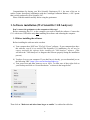
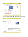
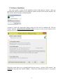
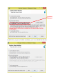
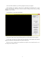
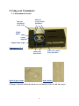
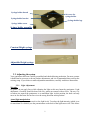
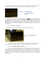
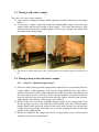
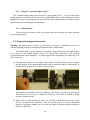
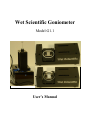
Wet Scientific Goniometer
Model G1.1
User’s Manual
Congratulations for buying your Wet Scientific Goniometer G1.1, the state of the art in
surface science that allows combination with the Centrifugal Adhesion Balance, a 2013 patent
that is solely produced by Wet Scientific LLC.
Please read this manual carefully before using the goniometer.
1. Software installation (Wet Scientific CAB Analyzer):
Don’t connect the goniometer to the computer at this stage!
Before connecting the G1.1 to the computer you need to install the software. Connect the
G1.1 with its two USB cables only after installing the software and rebooting the computer.
1.1. Before installing the software
Before installing the software make sure that:
a) Your computer does NOT have "FlyCap2 Viewer" software. If your computer does have
this software, even if it is a result of Wet Scientific G1.1 installation, you will need to
remove (uninstall) this software before installing the "CAB Analyzer" software. (This
will allow the "CAB Analyzer" to integrate this software properly during the installation
process).
b) You have Java on your computer. If you don't have it already, you can download java at
the following URL: https://java.com/en/download/index.jsp
c) Your screen text and other items are set to 100%. To make sure of that, right click on
your Desktop and click on “Screen Resolution.” as shown in the image below:
Then click on “Make text and other items larger or smaller” as outlined in red below:
1 Tick the radio button next to “Smaller – 100%” which is outlined in red and then click on
“Apply” which is outlined in green in the following image:
With this you complete the screen adjustment.
2 1.2. Software Installation
Now your system is ready for the installation of the CAB Analyzer software. After you
download the software installer to your computer, double click the icon to run the installer. The
first window that will prompt will look like this:
Continue to follow the instructions during which you will also be installing the "FlyCap2
Viewer" software. Special attention should be paid to the part in which you are asked to select
interface driver as follows:
When this screen shows up, you should check the box next to “I will use USB cameras.” but
uncheck the box that says “Install USBPro – Point Grey USB Interface Driver” (see picture
below)
3 Uncheck
this box!
So that before you proceed with the installation, your screen should look like this:
4 At the end of the installation, you will be prompted to restart your computer.
After restarting your computer, connect the two USB cables of Goniometer G1.1 to your
computer and launch the CAB Analyzer software by double clicking the shortcut that says “Drop
Imaging” on your desktop.
You should have a screen that looks like this:
Click on the "Open Camera" option following which you will be asked to select a camera.
At this stage, reach with your fingers inside the goniometer on the opposite side from the
light source and remove the protecting cover from the camera lens.
With this, you have completed your installation successfully, and you should be able to see a
live image on the computer screen.
5 2. Using your Goniometer
2.1. Instrument Overview
Holes for
installation
in the CAB
Holes for
syringe holder
placement
Sample
holder
Sample
supporter
Sample holder stripes
Goniometer G1.1:
Anchors for
dome holder
Optical glass dome:
Groove for optical
dome placement
; dome holder:
(If image with and without the dome are not identical clean it with lens paper)
6 Syringe holder thread
Set screw for
syringe holder
Syringe holder bracket
Syringe holder legs
Syringe holder screw
Syringe holder assembly:
Constant Height syringe:
Adjustable Height syringe:
2.2. Adjusting the system
Your goniometer has been carefully assembled and checked during production. For most systems
it should not be necessary to do any further adjustments, and it is recommended that you keep the
existing setup. If you choose to make adjustments nonetheless, carefully read these instructions.
2.2.1. Light Adjustment
Warning:
Be gentle, do not apply force while adjusting the light as this may harm the goniometer. Light
adjustment, if needed, should be done with very gentle movements with no force. The way it is
set when you unpack the goniometer is on maximum light. At this position, the knob can only
move in one direction. Do not force it to the wrong direction at this position!
Actual light manipulation
If needed, the goniometer can work at low light levels. To reduce the light intensity (which is set
for maximum as a default), use the potentiometer at the back of the light source side. This allows
7 light adjustments. Locate the potentiometer according to the image below (a small blue square at
the center of which there is a grey circle with a cross that fits a Phillips screwdriver):
Potentiometer (grey
crossed circle in a blue
square).
To adjust the light, gently use a Phillips screwdriver to gently turn the potentiometer and
observe the changes in the light intensity. Should you feel any resistance, do not force the
potentiometer! The resistance means you have reached the end of the scale. The light
adjustment does not mean necessarily brighter or less bright image as this is also a function of
the shutter setting. Different light and shutter setups will require choosing different thresholds in
the software.
2.2.2. Camera focus Adjustment
The focus adjustment hole is at the back side of the goniometer as shown below:
Focus adjustment hole
Use a Philips screwdriver ideally of diameter of about 4.8 mm and insert into the deep in
this hole until you feel resistance. Turn the screwdriver and adjust the focus accordingly.
2.2.3. Camera Height and angle Adjustment
The Camera height and angle adjustment has been optimized so that when a surface is
placed properly in place, the vision is optimal. It is recommended that you do not change this
setting. However, if you still want to modify it, there is an access to two screws from two slits at
the top of Wet Scientific goniometer G1.1. Note that since there are two screws, any height
adjustment with one screw will cause a slight angle change that needs to be corrected with the
opposite screw.
8 2.3. Placing a sold surface sample
There are a few ways to place samples:
a) You can place a sample by using a double sided tape and stick it directly on the sample
holder.
b) You may use a longer sample that reaches the sample holder stripes. Press down the
sample holder and insert the sample as shown below. The easiest dimensions to work
with are close to those of the sample supporter. This way you can place the sample from
the middle of the sample holder.
c) You can use a double sided tape to glue a small sample to the sample supporter and insert as in
(b).
2.4. Placing a drop on the solid surface sample
2.4.1. Using the "adjustable height syringe":
a) Decide on which of the legs of the syringe holder touches first its corresponding "hole for
syringe holder" on the goniometer. Note that the syringe holder has four legs, while a
surface is defined by 3 points. This means that one of the legs will not necessarily touch
the surface (in most cases it will not). This is a normal situation. You need to decide for
yourself which two legs are placed first and which leg follows. Based on that decision,
slight changes in the position of the syringe can be induced.
b) Decide on the way to insert the "adjustable height syringe" to the syringe holder. Note
that the syringe's top has a side with wider round margin, and a side with flat narrow
margin. Based on this and on the position of the scales on the syringe, you can insert the
syringe in the syringe holder in the same way every time, bringing you close to the same
position on the sample holder.
c) Decide on a height for the syringe and lock the "syringe holder screw" in that position
using the "set screw for syringe holder".
9 2.4.2. Using the "constant height syringe":
The "constant height syringe" does not fit the "syringe holder screw". To use it, take out the
syringe holder screw and insert it directly to the syringe holder thread. This configuration can be
slightly less accurate in reproducing the same position on the sample holder, but at times can be
quicker while still enabling good reproducibility.
2.4.3. Additional tips:
You may keep the syringe inside the syringe holder and carrying the whole assembly
when pumping liquids.
2.5. Evaporation suppression system
Warning: The optical dome is fragile, it can break if you drop it. Nonetheless, there is no
problem applying pressure on it using the designated rubber “dome holder”.
The optical dome is used to suppress evaporation. Simple placement of the optical dome
in its groove on the sample holder (“Groove for optical dome placement”) will suppress
evaporation but not seal it completely. To further suppress the evaporation you can do any or all
of the following:
a) After placing the dome, use the rubber “dome holder” to hold the dome in place: identify
the four anchors for the dome holder and use them to anchor the rubber “dome holder” to
its place while the dome is in its place as shown below:
Note that the dome holder is naturally adhering to the dome as it needs to grip the dome.
Therefore you need to place its central hole at the top of the dome so that the 4 stripes
will have similar tensions.
b) Either before or after placing the dome you can add a small amount of water to the
Groove for optical dome placement. This will use the groove as a mote and further
suppress evaporation. Adding step (a) to this step blocks evaporation almost completely
(but not completely).
10 c) Optional (not all components supplied, recoverable damage occurs): Before placing the
dome you can add a small amount of oil such as tetradecane or other simple oils to the
“Groove for optical dome placement”. This dissolves the white rubber and allows it to
make hermetic seal with the dome. Evaporation will now be suppressed to the maximum,
leaving a water drop for weeks or longer. With this configuration the dome will remain
attached to the groove. It can be detached from the groove by dissolving the white rubber
in the groove using hexane. Wet Scientific can sell additional material for creating a new
layer of white rubber in the groove (this is not supplied with the package).
11 3. Using the software:
Note the following:
3.1. The camera's high resolution loads the memory of the computer.
3.2. The actual frame rate is a function of the frame rate that the camera feeds the computer
AND the frame rate the computer can accept those frames. Many computers are slower
to accept images than the camera ability to deliver, and they set the limiting factor for
frame rates.
3.3. The "Open Camera" option opens the camera to show a streaming picture, but not to
record.
3.4. To record, press the "Record" knob under the "Open camera" knob and follow the
instruction from that point on.
3.5. Try to keep the recording time to a minimum - it will help save memory.
3.6. Choose the right setting: make sure the shutter is set high enough to allow the
background around the drop to appear white (if this is not possible, then as white as
possible) outside the drop.
3.7. Important: Choose the shutter so that the background is white also outside the drop
edges, while the drop edges themselves are as black as possible. Thus, the solid surface
appears a little lower than the reflecting plane. This will supports proper performance of
the software.
3.8. Calibrating the pixels to mm conversion factor: Use an item of about 4 mm and measure
its exact size with a caliper. Place it on the sample holder and record a short film. The
film will be stored as a set of images. Choose any of these images and open it in Paint.
There you can measure the number of pixels that your object actually occupies. Write
that number in its proper place in the Drop Imaging software.
3.9. A "Calibration image" is not different from any other, but parameters used in it can be
used by the software for the analysis of any number (batch) of images. There are two
parameters that will need to be inserted:
3.9.1. Reflection plane position: There are two green cursers at the edge of the screen.
They need to be placed at the reflecting plane of the drop (the place where the three
phase contact line needs to pass). Once the reflecting plane is defined, the software
12 remembers it until it is replaced by another one. In this sense, the image chosen was
used to "calibrate" the reflection plane.
3.9.2. The threshold value is the value from which on the software considers a pixel as a
drop pixel, namely as a black pixel. The threshold value depends on the
experimental system . Your calibration image will set the threshold value to be used
for the corresponding batch of images. As a default, you can choose a value of 100
and see if the fit is reasonable. Make sure item 7 above is satisfied before choosing
a threshold value.
3.9.3. After choosing a "Calibration image", click process image to process it. Based on
the fit observed, decide if the threshold value should be modified.
3.10.
10. Once you decide on your system's values in item 9 above, you may proceed to
analyze a batch of images (i.e. a movie). The movie will be stored as a batch of single
images (you may decide to convert them back to a movie using "Window Live Movie
Maker" or other available free programs).
In addition to the images, the same folder in which they are stored now holds two files that can
be open with Excel and contain the time of each image and the physical values (contact angle,
drop height, etc.).
13