1
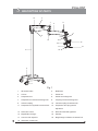
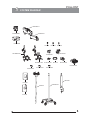
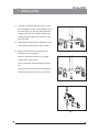
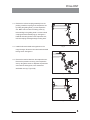
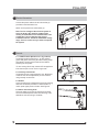
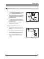
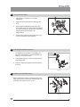
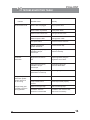
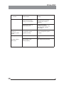
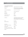
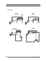
R
PRIMA DNT
User Manual
Operating Surgical Microscopy
To ensure proper use of this instrument as well as to avoid injury while operating
instrument, understanding this manual completely before use is highly recommended.
Prima DNT
CONTENTS
1
INTRODUCTION
1
2
SAFETY INSTRUCTIONS
2
3
SPECIAL INSTRUCTIONS
3
4
UNPACKING
4
5
DESCRIPTION OF PARTS
5
6
SYSTEM DIAGRAM
6
7
INSTALLATION
8
ELECTRICAL CONNECTIONS
9
9
CONTROLS
9
10
INSTRUCTIONS FOR USING THE MICROSCOPE
10
10.1
SETTING UP MICROSCOPE
10
7-8
10.2 SETTING UP MAGNIFICATION
10
11
HOW TO FOCUS THE OBJECT
11
12
CHANGING THE OBJECTIVE/EYEPIECE
11
13
REPLACING THE ILLUMINATION SOURCE
11
14
FUSE REPLACEMENT
12
15
ADJUSTMENT OF TENSION WHILE USING ACCESSORIES
12
16
DISINFECTION AND STERILIZATION
12
17
CLEANING AND SERVICING
13
18
TROUBLE SHOOTING TABLE
19
SPECIFICATION
14-15
16
1
Prima DNT
INTRODUCTION
The LABOMED Prima DNT is a surgical and diagnostic microscope, which is adaptable for different surgical
needs without compromise to performance.
The microscope provides extremely high optical image quality, good depth of focus and wide field of view for
precise surgery. Illumination control, inbuilt tilt, adjustment of the observation head help to reduce the
surgeon’s work fatigue and allow comfortable use over long period.
Salient features of this Microscope are:
1.
The observation head can easily be positioned with the help of suspension arm .
2.
An advanced 5-step magnification changer allows an optimal magnification for a particular surgery from
five different magnifications.
3.
Cold light illumination with a high intensity 50W LED lamp is provided using a fiber optic guide for proper
illumination. The illumination is further adjustable up to its most suitable brightness using intensity
control knob suitably located at the suspension arm, and is easily approachable to the surgeon.
4.
When the microscope is not in use, the suspension arm can be folded over the main body to store it
compactly.
5.
Rigid H-form base with castor wheels provides greater stability as well as mobility to the instrument.
1
2 SAFETY INSTRUCTIONS
Prima DNT
1.
This microscope is manufactured according to the safety norms as per CE regulation and FDA
approval .
2
This microscope is intended for use only as prescribed in this manual.
3.
Servicing and repairs are allowed through authorized persons only.
4.
Replace burnt out fuses by live fuses of the same type only (rated voltage, rated current, switch – off
characteristics.)
5.
Use mains plug and mains socket both with protective earth conductors only.
6.
Do not use force while fixing cable connections. If the male and female parts do not readily connect,
make sure that they are appropriate for one another. If any of the connectors are damaged. Please
contact the representative.
7.
Make sure that inlets and outlets of ventilation system for cooling the housing are open (not
covered).
8.
The microscope is built for use in dry rooms only. Take care that no fluids enter the microscope
components. Do not place any fluid-filled container on top of instrument.
9.
Microscope is protected against overheating through a thermal cut-off.
10.
The manufacturer will not accept any liability for damage caused by unauthorized persons
tampering with the instrument; this will also forfeit any rights to claim warranty.
11.
It is recommended to use the instrument only with the accessories supplied. In case you wish to
use other accessory, make sure that LABOMED has certified that its use will not impair the safety of
instrument.
Very important: For identification, service people must know the serial number of the microscope.
2
3 SPECIAL INSTRUCTIONS
Prima DNT
3.1 Before every use and after re-equipping the instrument
1.
Check all electrical connections.
2.
Attach sterilized covers, panels or caps which have been re-moved or opened.
3.
Pay special attention to labels on the instrument, such as caution label, warning triangles
with exclamation marks or notes.
4.
Do not cover any ventilation openings.
3.2 When instrument is in use
1.
Avoid looking directly into the light source, microscope objectives lens or light guide.
2.
When the illumination is on, the light guide must be connected at both ends. Otherwise there
is a risk of fire or burn injuries.
3.
Any kind of radiations has a detrimental effect on biological tissue. This also applies to
illuminating the surgical field, therefore adjust the brightness and duration of illumination on
the surgical field to the absolute minimum required.
4.
Adjust tension of suspension arm as per convenience.
3.3 After every use of the instrument
3
1.
Switch off the mains supply to the instrument.
2.
When the microscope is not in use, the suspension arm can be folded over the main body for
compact storage.
4 UNPACKING
Prima DNT
The appliance is delivered in sub-assembled groups along with one set of Installation Kit and
one instruction / service manual.
Please check following at the time of unpacking:
1.
Mobile supporting base with brakes on castor wheels.
2.
Column
3.
Swivel arm and Suspension arm assembly with fibre optic cable and illumination
assembly
4.
Cover for swivel arm (pre-fitted to the microscope)
5.
Inclined arm with magni-changer assembly and objective (as ordered)
6.
Observation Head
7.
Paired Eye Pieces; as ordered
8.
Power Cord
9.
Set of sterilizable caps
10. Installation Kit
a) Allen Wrench 5.00mm
b) Allen Wrench 8.00mm
11. Instruction cum Operating Manual / Service Manual
4
5
Prima DNT
DESCRIPTION OF PARTS
13
4
7
11
5
9
6
8
10
12
14
18
17
3
15
16
2
1
Fig. 1
1.
Wheel with brake
2.
Metal base
3.
Column
4.
Swivel arm
5.
Suspension arm
6.
Swivel arm locking knob
7.
Suspension arm movement locking knob
8.
Coupling movement locking knob
9.
Inclined coupling
10.
Inclined coupling movement knob
11.
Suspension arm hydraulic movement lock
12.
Suspension arm spring tension
adjustment
5
13.
Swivel arm covers
14.
Binocular head with eyepieces
15.
Magnification changer
16.
Handles
17.
Common main objective
18.
Magnichanger inclination movement lock
19.
Illumination control knob
6
Prima DNT
SYSTEM DIAGRAM
A616500-811
613800-815
613400-820
612086-600
1271094
A6138000-000
6122012
6122016
6122015-800
613200-800
A6138000-100
6134105-102
6134105
6134100-800
6135000-809
6133250-801
6133300-801
6133400-801
6137300
6137500
6137200
6165000-817
6137100
6
7 INSTALLATION
Prima DNT
7.1 The base is installed by fixing the column on the
base. Engage the column to the indexing screw on
the base. See Fig. 2. Align the tapped hole of the
upright in the screw seat, Hold the upright firmly
and tight the allen screws from the bottom of the
base. See Fig.3.
7.2 After fixing the upright to the H shape base, make
sure the parts are fitted to each other properly.
7.3 Retrieve the swivel arm and suspension arm
Fig. 2
assembly from the packing box.
Install the swivel arm assembly on the upright
holding shaft (1). See figure 4.
Lock the swivel arm with threaded plug from the
top.
Loosen the swivel arm lock knob and suspension
arm locking arm knobs so that it can be rotated.
Fig. 3
1
Fig. 4
7
Prima DNT
7.4 Retrieve the inclined coupling assembly from the
3
packing. Install the coupling to the suspension arm
by sliding the guiding shaft (1) to the suspension
arm. Make sure to loosen the locking screw (2)
before sliding in the guiding shaft. Lock the inclined
2
1
coupling with the threaded plug (3). See figure 5.
Install all the locking knobs to the suspension arm,
inclined coupling and magnichanger locking knob.
7.5 Install the binocular head and eyepieces on the
Fig. 5
magni-changer. Secure the binocular head with head
locking screw. See figure 6.
7.6 Remove the caution label from the suspension arm.
Remove the protection screw (1) from suspension
arm by using allen screw 5.0. Replace the protection
screw with the locking knob, riser washer and
sterlizable cover (2). Tight it fully.
Fig. 6
2
Caution
Caution
Caution
Caution
1
Fig. 7
8
Prima DNT
8 Electrical Connections
Connect the power cable to the AC inlet socket (2)
provided on the illumination box.
Switch on the power from on/off switch (2).
Note: The line voltage of the electrical system is
set in the factory the rated line voltage of the
country of destination which must be either 110V
or 220V AC. The line voltage at the sight of
installation must lie within the admissible voltage
range. If this is not the case you must not operate
the system.
1 2
Fig. 8
9 Controls
9.1 ON/OFF switch (Shown as 2 in fig. 8 above)
It is located under the swivel arm. At ‘ON’ position,
green LED glows and cooling fan starts running. Keep
the intensity control knob at minimum level before
switching on the system.
To save burning life of lamp, switch OFF the appliance
if the microscope is not in use for longer time.
9.2 Intensity control knob
It is located in front of the suspension arm. Brightness
of field of view can be adjusted as per user comfort
using intensity control knob.
9.3 Brakes
Locks the stand from unwanted movement by pressing
down the two brakes provided on caster wheels. To
unlock press upper portion of brake. See Figure 8.
Fig. 9
9.4 Swivel arm locking knob
This knob helps you to lock the movement of swivel
arm at the desired position after initial focusing of the
attendance area by turning it clockwise.
Fig. 10
9
Prima DNT
10 Instructions for using the microscope
Setting up of Microscope:
1
Lock all the brakes on base wheels after setting
up of microscope on the attendance area for
stability.
2
Adjust tension on suspension arm using tension
adjustment screw as per your convenience by
turning the knob clock
wise or anti-clock wise.
3
4
Lock the Up & Down movement of suspension
arm using locking knob after coarse focusing of
the attendance area.
11a
11b
11c
Fig. 11
Adjust the eye distance as per IPD scale
according to your convenience.
Setting up of magnification (Ref. Fig. 11)
1
Adjust to highest magnification with one of the
rotating knobs (11a) provided at magnification
changer.
2
Fine focusing is done through FOV knob (11b).
3
Absolute centering of observation area in field
of view can be done by manual handle(11c).
4
Make sure that the magnification changer is
engaged in the index point at the click stop
position.
Fig. 12
10
Prima DNT
11
How to focus the object
1.
Adjust both the eyepieces to ‘0’ diopter
adjustment.
2.
Adjust IPD of the observation head using IPD
scale.
3.
Bring highest magnification factor in the click
stop position using one of the knobs provided at
the magni-changer unit. By doing so observation
area will remain par-focalized in all
magnifications.
4.
Fine focusing is done by using FOV knob (1) by
turning it clockwise or anti clockwise.
1
Fig. 13
12 Changing the objectives/ eyepieces
1. The objectives can be taken out by rotating it in
anti-clock wise direction. It can be threaded in by
rotating in clock wise direction.
2. To install the eyepieces, insert in the eye tubes of
observation head.
3. A range of objectives/eyepieces can be selected
by choice.
Fig. 14
13 Replacing the illumination source
Open the swivel arm cover’s. Detach the fibre optic
cable and replace the illumination assembly with new
assembly. Secure pack the arm cover’s.
1
Fig. 15
11
Prima DNT
14 Specifications
14 Technical Data (Specifications)
Type:
Base (Dimensions):
Stand Height:
Weight of complete microscope:
Elevation Stroke:
Stand Height in Horizontal Position:
Field of illumination with F.O.V.
Length of arm extended:
Floor stand
775mm width
762mm length
1676mm
72 Kg. Approx.
600mm
1300mm
f=200mm objective; Ø85.0mm
1702mm
15 Adjustment of Tension while using Accessories
After Supplementary accessories are mounted, the additional load of suspension arm must be
compensated by adjusting tension on tension control screw provided on suspension arm by moving it
clock wise or anticlockwise.
16 Disinfection and Sterilization
For Diagnosis:
Moisten smooth cotton with antiseptic fluid (for example Sagrotan – P); when required, clean often
touched parts, like rotating knobs, handles and so on.
After surgery:Sterilizable polymer covers are provided on every part that require to be touched during operation.
Sterilize them after every use of the instrument.
12
17 CLEANING AND SERVICING
17.1
Prima DNT
Cleaning of optical surfaces:
Remove coarse dirt particle with a clean dry air from optics outer surfaces (Objectives,
Eyepieces).
Moisten smooth cotton cloth with lens cleaning agent and wipe on the lens surface
gently starting from the middle of the lens to the outer edge.
17.2
Cleaning of mechanical surfaces:
All mechanical surfaces of the equipment can be cleaned by wiping with a moist cloth.
Don’t use any aggressive or abrasive cleaning agents.
Any household dish washing fluid can be used for cleaning residue.
17.3
Servicing:
Service whenever required, inform after-sale service.
13
18 TROUBLESHOOTING TABLE
Problem
No Illumination at all
Insufficient
Illumination
Prima DNT
Possible Cause
Remedy
Power cable not plugged
Plug in power cable.
Power switch not pressed
Press power switch
Defective instruments fuse
Change instrument fuse
Defective power cable
Change power cable
Line power failure
Contact in-house Techician
Failure of suspension
system electronics
Contact service dept.
Light guide not properly
inserted in lamp or
microscope.
Insert light guide to the
maximum intensity.
Brightness level set too
low
Adjust brightness using the
brightness control knob.
Light guide not properly
inserted in lamp or
microscope.
Insert light guide to the
maximum illumination
Defective light guide
(illumination not uniform)
Chance light guide.
Halogen lamp in the
illumination system
remains dark, and
fan is running
Knob for brightness control
Lamp module has no
contact.
Insert lamp module properly.
Halogen lamp goes
constantly off and on
during operation.
Defective halogen lamp.
Switch to backup lamp.
Ventillation slots are
covered or contaminated
Ventillation slots must be clear,
clean them if necessary.
14
Prima DNT
Problem
15
Possible Cause
Remedy
Thermal cut-off in lamp
housing is contaminated.
Clean thermal cut-off with a
dry brush; blow it clean, if
necessary
Defective fan. Failure of
system electronics.
Contact service dept.
Illuminate surgical field using
an Or illuminator. Contact
service dept.
Up & Down motion
of screw on
suspension system
too stiff
Friction adjustment screw
on suspension system
tightened too firmly.
Loosen friction adjustment
screw on suspension system
as require
Microscope Unstable
Brakes on wheels not
Use Brakes.
used.
No image visible in
field of view.
Magnichanger is not
indexed properly.
Index magnichanger properly.
19 SPECIFICATIONS
Technical Data (Specifications)
Binocular tubes
Ergonomic binocular tube 0°-210° tiltable
Eyepieces
WF 10x/16mm with eye guards; optional WF
12.5x/16mm; WF 16x/16mm; WF 20x/12mm
Apochromatic magnichanger
0.4x, 0.6x, 1.0x, 1.6x & 2.5x
Objective
f=250, manual fine focus
Light source
27W LED
Built-in filters
Green
Vertical movement of arm
600mm
Microscope carriers
Ergonomic
Accessories
Assistant Binocular attachment, iVu OP Beam
splitter integrated digital camera Module;
Double Beam splitter; 0-210° inclinable ergo tube
Type:
Floor stand
Base (Dimensions):
600mm width
620mm length
Stand Height:
1677mm
Weight of complete microscope:
72 Kg. Approx.
Elevation Stroke:
600mm
Stand Height in Horizontal Position:
1100mm
Field of illumination with F.O.V. f=200mm
Ø85.0mm
objective
16
Dimensions
1124.6
1124.6
525
525
1124.6
525
1464.6
843
525.0
1733.09
767.7
1245
930
1280.8
536
17
www.laboamerica.com
Our policy is one of continuous development. Labo America, Inc., reserves the right to change design and specifications without prior notice.
Labo America Inc.
920 Auburn Court
Fremont
CA 94538
U.S.A.
Telephone: 510 445 1257
Fax: 510 991 9862
[email protected]
LABOMED and Prima DNT are registered trademarks of Labo America, Inc.
With a policy of continuous development, Labo America, Inc. reserves the right to change design and specifications without prior notice.
© 2010 Labo America, Inc. | 6138000-990A 02-2010
ISO 9001 : 2008
File No. A9020


![[Unlocked] SC-2042](http://vs1.manualzilla.com/store/data/005660029_1-1367986a5e7a7fe673239a9957384234-150x150.png)