1
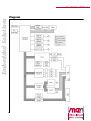
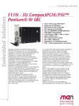
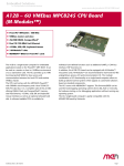
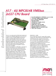
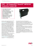
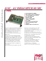
A14C Data Sheet - 2009-03-16
Embedded Solutions
A14C - 6U VME64 MPC8540 SBC
/ PMC
n
n
n
n
n
n
n
n
n
n
n
n
PowerPC® MPC8540 / 800MHz
FPGA 12,000 LEs (approx.144,000 gates)
1-slot 64-bit VMEbus master and slave
Up to 2 GB (ECC) DRAM
NAND Flash, FRAM
Graphics via PMC or FPGA
2 Gigabit/1 Fast Ethernet
Up to 6 COMs
Parallel ATA for onboard hard disk
Further I/O individually via FPGA
2 PMC slots
MENMON™ BIOS for PowerPC® cards
The A14C is an advanced PowerPC® based single-board
binary I/O etc. can be realized as IP cores in FPGA
computer for embedded applications. It features full
for the needs of the individual application. The
VME64 support and it can be used as a master or a
corresponding PHYs are available via SA-Adapters™ on a
slave in a VMEbus environment. The A14C provides 1
transition module to the rear.
MB local shared SRAM for slave access and
The FPGA acts as a standard PCI device on the A14C.
communication between the local CPU and another
The FPGA functions are loaded by software during power-
VMEbus master.
up within less than 1s. FPGA updates can be carried
The A14C is controlled by an MPC8540 integrated
out dynamically during operation.
PowerPC® processor working at 800MHz. The SBC is
In addition, the A14C can be equipped with PMC
equipped with a DDR SO-DIMM socket for data storage,
mezzanine cards supporting 64 bits/66 MHz as well as
with NAND Flash for program storage as well as with
front I/O and rear I/O (PIM).
non-volatile FRAM. The board provides front-panel
The A14C comes with MENMON™ support. This
access for two Gigabit Ethernet, one fast Ethernet
firmware/BIOS can be used for bootstrapping
and one COM via four RJ45 connectors. Four more
operating systems (from disk, Flash or network),
UARTs are optionally accessible via SA-Adapters™ for
for hardware testing, or for debugging
front connection.
applications without running any operating system.
Additional functionality such as graphics, touch, CAN,
1
®
A14C Data Sheet - 2009-03-16
Embedded Solutions
Technical Data
CPU
n PowerPC®
o MPC8540 PowerQUICC™ III
o 800MHz (666..833MHz optional)
o e500 PowerPC® core with SPE APU and MMU
o Integrated Northbridge and Southbridge
o High memory bandwidth
Memory
n 2x32KB L1 data and instruction cache, 256KB L2 cache /
SRAM integrated in MPC8540
n Up to 2GB SDRAM system memory
o SO-DIMM slot for SDRAM modules
o DDR2100 with or without ECC
o 133MHz memory bus frequency
n Up to 1GB soldered NAND Flash (and more), FPGA-controlled
n Up to 16MB additional SDRAM, FPGA-controlled, e.g. for
video data and NAND Flash firmware
n 8MB boot Flash
n 32KB non-volatile FRAM
n Serial EEPROM 4kbits for factory settings
Mass Storage
n Parallel IDE (PATA)
o One port for hard-disk drives
o Drive can be connected via ribbon cable or mounted
directly on the CPU board using MEN adapter kit
(instead of PMC modules)
o Only one VMEbus slot needed even with hard disk
o PIO mode 0 support
n Up to 1GB soldered ATA NAND Flash (and more),
FPGA-controlled
I/O
n Three Ethernet channels
o Two 10/100/1000Base-T Ethernet channels
o One 10/100Base-T Ethernet channel
o Three RJ45 connectors at front panel
o Two onboard LEDs to signal LAN Link and Activity
n One RS232 UART (COM1)
o One RJ45 connector at front panel
o Data rates up to 115.2kbits/s
o 16-byte transmit/receive buffer
o Handshake lines: CTS, RTS
n One LVTTL UART (COM10)
o FPGA-controlled
o Accessible via rear I/O
o Data rates up to 115.2kbits/s
o 60-byte transmit/receive buffers
o Handshake lines: CTS, RTS; DCD, DSR, DTR; RI
n Quad UART (COM20..COM23)
o Physical interface using SA-Adapters™ via 10-pin
ribbon cable on I/O connector
2
RS232..RS485, isolated or not: for free use in system
(e. g. cable to front)
o Data rates up to 115.2kbits/s
o 128-byte transmit/receive buffer
o Handshake lines: CTS, RTS; DCD, DSR, DTR; RI
GPIO
o 39 GPIO lines
o FPGA-controlled
o Accessible via rear I/O
o
n
Front Connections
n Three Ethernet (RJ45)
n COM1 (RJ45)
n COM20..COM23 (optional, instead of PMC modules, or in
second front-panel slot)
n PMC 0 and 1
Rear I/O
n COM10
n GPIO
n Mezzanine rear I/O: PMC 0
FPGA
n Standard factory FPGA configuration:
o Main bus interface
o 16Z070_IDEDISK - IDE controller for NAND Flash
o 16Z043_SDRAM - Additional SDRAM controller (16MB)
o 16Z023_IDENHS - IDE controller (PIO mode 0;
non-hot-swap)
o 16Z025_UART - UART controller (controls COM10)
o 16Z034_GPIO - GPIO controller (40 lines, 5 IP cores)
n The FPGA offers the possibility to add customized I/O
functionality. See FPGA.
Mezzanine Slots
n Two PMC slots
o Compliant with PMC standard IEEE 1386.1
o Up to 64-bit/64-MHz, 3.3V V(I/O)
o PMC I/O module (PIM) support through J4
Miscellaneous
n Real-time clock with GoldCap backup
n Power supervision and watchdog
n Reset button, GPIO-controlled, in ejector handle
Local PCI Bus
n 32-bit/33-MHz, 3.3V V(I/O)
n Compliant with PCI Specification 2.2
®
A14C Data Sheet - 2009-03-16
Embedded Solutions
Technical Data
VMEbus
n Compliant with VME64 Specification
n Slot-1 function with auto-detection
n Master
o D08(EO):D16:D32:D64:A16:A24:A32:ADO:BLT:RMW
n Slave
o D08(EO):D16:D32:D64:A16:A24:A32:BLT:RMW
n 1MB shared fast SRAM
n DMA
n Mailbox functionality
n Interrupter D08(O):I(7-1):ROAK
n Interrupt handler D08(O):IH(7-1)
n Single level 3 fair requester
n Single level 3 arbiter
n Bus timer
n Location Monitor
n Performance
o Coupled read/write D32 non-block transfer rate 6.5 MB/s
o DMA read/write D32 BLT transfer rate 12.1 MB/s
o DMA read/write D64 MBLT transfer rate 25 MB/s
EMC
n Tested according to EN 55022 (radio disturbance),
IEC1000-4-2 (ESD) and IEC1000-4-4 (burst)
BIOS
n MENMON™
Software Support
n VxWorks®
n Linux (ELinOS)
n QNX®
n For more information on supported operating system
versions and drivers see Software.
Electrical Specifications
n Supply voltage/power consumption:
o +5V (-3%/+5%), 3A typ.
o +12V (-5%/+5%), only provided for PMCs that need 12V
o -12V (-5%/+5%), only provided for PMCs that need 12V
n MTBF: 92,800h @ 40°C (derived from MIL-HDBK-217F)
Mechanical Specifications
n Dimensions: standard double Eurocard, 233.3mm x 160mm
n Weight (without PMC modules): 450g
Environmental Specifications
n Temperature range (operation):
o 0..+60°C
o Airflow: min. 10m³/h
n Temperature range (storage): -40..+85°C
n Relative humidity (operation): max. 95% non-condensing
n Relative humidity (storage): max. 95% non-condensing
n Altitude: -300m to + 3,000m
n Shock: 15g/11ms
n Bump: 10g/16ms
n Vibration (sinusoidal): 2g/10..150Hz
n Conformal coating on request
Safety
n PCB manufactured with a flammability rating of 94V-0 by
UL recognized manufacturers
3
®
A14C Data Sheet - 2009-03-16
Embedded Solutions
Diagram
4
®
A14C Data Sheet - 2009-03-16
Embedded Solutions
Configuration & Options
Standard Configurations
Article No.
CPU Type
01A014C00 MPC8540
Clock
System RAM NAND Flash Additional
SDRAM
FRAM
Boot Flash
Mezzanine
Slots
Operation
Temperature
800 MHz
512 MB (no 128 MB
ECC)
32 KB
8 MB
2 PMC
0..+60°C
16 MB
Options
CPU
n Type
o MPC8540
o MPC8560
n Clock
o 666..833 MHz
Memory
n System RAM
o 256 MB, 512 MB, 1 GB or 2 GB
o With or without ECC
n NAND Flash
o 0 MB up to maximum available
n Additional SDRAM
o 0 MB or 16 MB
n FRAM
o 0 MB or 32 MB
n Boot Flash
o 8 MB or 16 MB
I/O
n Quad UART (COM20..23)
o Direct onboard connection via 10-pin connectors,
instead of PMCs
n Front Connections
o D-Sub instead of RJ45 connectors
Mezzanine Slots
n 2 PMC
n 3 PC-MIP®
Operation Temperature
n 0..+60°C
Please note that some of these options may only be
available for large volumes. Please ask our sales staff
for more information.
5
®
A14C Data Sheet - 2009-03-16
Embedded Solutions
FPGA
Flexible Configuration
n This MEN board offers the possibility to add customized
I/O functionality in FPGA.
n It depends on the board type, pin counts and number of
logic elements which IP cores make sense and/or can be
implemented. Please contact MEN for information on
feasibility.
n You can find more information on our web page "User I/O
in FPGA"
FPGA Capabilities
n FPGA Altera® Cyclone® EP1C12
o 12,060 logic elements
o 239,616 total RAM bits
n Connection
o Available pin count: 47 pins
o Functions available via onboard and rear I/O connectors
6
®
A14C Data Sheet - 2009-03-16
Embedded Solutions
Ordering Information
Standard Hardware
Software: VxWorks
01A014C00
10EM03-60
VxWorks BSP (MEN) for EM3, EM3A, EM8, EM8A,
EK7, A14C and F13
13P010-60
VxWorks UART driver (MEN) for P10 and P11
13Z025-60
VxWorks native driver (MEN) for
16Z025_UART, 16Z057_UART and 16Z125_UART
13Z100-60
VxWorks FPGA update tool (MEN)
MPC8540/800MHz, 512MB DRAM, 128MB NAND
Flash, 16MB graphics memory, 32KB FRAM, 2
PMC slots, 0..+60°C
SA-Adapters
05A013-00
Mounting kit for 4 SA-Adapters for 6U
VME/cPCI boards, incl. 1-slot front panel
and ribbon cable, without SA-Adapters
08SA01-00
RS232, not optically isolated, 0..+60°C
08SA02-00
RS422/485, half duplex, optically isolated,
0..+60°C
08SA02-01
RS422/485, full duplex, optically isolated,
0..+60°C
08SA02-07
RS422/485, full duplex, optically isolated,
-40..+85°C screened
08SA03-00
RS232, optically isolated, 0..+60°C
Software: Firmware/BIOS
08SA03-01
RS232, optically isolated, -40..+85°C
screened
14EM03-00
Systems & Card Cages
Miscellaneous
05F006-00
RS232 interface cable RJ45 to 9-pin D-Sub
(1 COM to 1 COM), 2m
0710-0028
Industrial PATA hard disk, 2.5", 80GB,
24hours/7days, for on-board mounting (hard
disk mounting kit may be required
additionally), -30..+85°C qualified
08AD71-00
AD71, 2.5" hard disk adapter for A13, A14,
A15, D6, D7
Software: QNX
10EM03-40
QNX BSP (MEN) for EM3, EM3A, EM8, EM8A,
EK7, A14C and F13
13Z025-40
QNX native driver (MEN) for 16Z025_UART and
16Z125_UART
13Z100-40
QNX FPGA update tool (MEN)
MENMON (Firmware) for EM3, EM3A, EM8, EM8A,
A14C and F13 (object code)
Documentation
20A014-00
A14C User Manual
20A014CER
A14C Errata
21APPN009
Application Note: 16Z025_UART and
16Z125_UART under Linux
21MENM-00
MENMON 2nd Edition User Manual
22Z025-ER
16Z025_UART Errata
For the most up-to-date ordering information and direct
links to other data sheets and downloads, see the A14C
online data sheet under » www.men.de.
Software: OS independent
13Z017-06
MDIS5 low-level driver sources (MEN) for
16Z034_GPIO and 16Z037_GPIO
Software: Linux
7
13Z014-90
Linux device driver (MEN) for PCI-to-VME
bridge on A12, A13, A14, A15, A17, A19, A20
and B11
13Z025-90
Linux native driver (MEN) for 16Z025_UART,
16Z057_UART and 16Z125_UART
13Z100-91
Linux FPGA update tool (MEN)
®
A14C Data Sheet - 2009-03-16
Embedded Solutions
Contact Information
Germany
MEN Mikro Elektronik GmbH
Neuwieder Straße 5-7
90411 Nuremberg
Phone +49-911-99 33 5-0
Fax +49-911-99 33 5-901
E-mail [email protected]
www.men.de
France
MEN Mikro Elektronik SA
18, rue René Cassin
ZA de la Châtelaine
74240 Gaillard
Phone +33 (0) 450-955-312
Fax +33 (0) 450-955-211
E-mail [email protected]
www.men-france.fr
USA
MEN Micro, Inc.
24 North Main Street
Ambler, PA 19002
Phone (215) 542-9575
Fax (215) 542-9577
E-mail [email protected]
www.menmicro.com
The date of issue stated in this data sheet refers to the Technical Data only. Changes in ordering information given herein do not affect the date of issue.
All brand or product names are trademarks or registered trademarks of their respective holders.
Information in this document has been carefully checked and is believed to be accurate as of the date of publication; however, no responsibility is assumed for
inaccuracies. MEN Mikro Elektronik accepts no liability for consequential or incidental damages arising from the use of its products and reserves the right to
make changes on the products herein without notice to improve reliability, function or design. MEN Mikro Elektronik does not assume any liability arising out of
the application or use of the products described in this document.
The products of MEN Mikro Elektronik are not suited for use in nuclear reactors or for application in medical appliances used for therapeutical purposes.
Application of MEN's products in such plants is only possible after the user has precisely specified the operation environment and after MEN Mikro Elektronik
has consequently adapted and released the product.
Copyright © 2010 MEN Mikro Elektronik GmbH. All rights reserved.
8
®