1
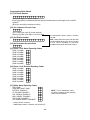
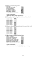
INSTALLATION
MANUAL
PC25OO
NOTES ON UL INSTALLATION
This equipment is UL listed in accordance with UL standard 1023 (Household Burglar Alarm System
Units), UL standard 985 (Household Fire Warning Units) and UL standard 1635 (Digital Alarm
Communicator System Units).
This equipment has the capability of being programmed for operational features that are not allowed
for UL recognized installations. To stay within the standard for Household applications, the Installer
should stay within the following guidelines when configuring the system.
1. All components of the system should be listed for the intended application. Note elsewhere
in this manual, recommendations for smoke detectors and battery to be used with this
equipment.
2. If this system is configured for “Fire”, the installer should refer to NFPA Standards #74 for
details on locating smoke detectors. When the “Fire” feature is enabled, there must be at
least one UL recognized indoor Fire Alarm Warning Signalling Appliance.
3. Maximum allowed Entry Time = 45 seconds
Maximum allowed Exit Time = 60 seconds
Minimum allowed Bell Cutoff Time = 4 minutes
4. The “Split-Arming” feature is not allowed for UL recognized installations. The equipment
must be configured as a Single System.
5. User Bypass must be enabled so that a User Code is required to Bypass zones.
6. The installer should caution the User to NOT give system information to casual users. e.g.
Codes, Bypass methods, etc. to babysitters or home service people. Only the “One-Time”
Use Code should be given to the casual user.
7. The Installer should advise the User and note in the User Manual:
i) Service organization name and telephone number
ii) The programmed Exit time
iii) The programmed Entry time
TABLE OF CONTENTS
1. SPECIFICATIONS ...................................................................................................................... 3
2. FEATURES ................................................................................................................................. 4
3. INSTALLATION
Bench Testing ........................................................................................................................ 5
Mounting Panel ...................................................................................................................... 6
Hook-up Procedure ................................................................................................................ 6
Terminals Connections (Description of all Terminals) ............................................................ 6
Keypad Installation ................................................................................................................. 8
Power-up Procedure .............................................................................................................. 8
Hook-up Diagram ................................................................................................................... 9
Fire Alarm Diagram .............................................................................................................. 10
System Testing .................................................................................................................... 11
Instructing the End User ....................................................................................................... 11
4. KEYPAD FUNCTIONS
Introduction .......................................................................................................................... 11
Master Code ......................................................................................................................... 12
Installer’s Code .................................................................................................................... 12
Arming .................................................................................................................................. 12
Auto-Bypass/Home-Away Arming ........................................................................................ 12
Entry Delay Off Arming ................................ [ ][9][User Code] ........................................... 13
*
Disarming ............................................................................................................................. 13
Zone Bypassing (Shunting) .......................... [ ][1] .............................................................. 13
*
Trouble Display ............................................ [ ][2] .............................................................. 13
*
Alarm Memory Display ................................. [ ][3] .............................................................. 14
*
Switched Aux. Power Supply ....................... [ ][Hold Down 4] ........................................... 14
*
Programming new User Codes .................... [ ][5][Master Code] ....................................... 15
*
Programming Other User Functions ............ [ ][6][Master Code] ....................................... 15
*
- Setting the Internal Clock ............................................................................................... 16
- Automatic Arm ............................................................................................................... 16
- Quick Arm ...................................................................................................................... 16
- Door Chime .................................................................................................................... 16
- Installer’s Test ................................................................................................................ 16
- Bell Test ......................................................................................................................... 16
Utility Output Command ............................... [ ][7] or [ ][7][User Code] ............................. 17
*
*
Installer’s Programming Commands ............ [ ][8][Installer’s Code] ................................... 17
*
“Quick-Arm” Command ................................ [ ][0] .............................................................. 17
*
Keypad Zones ...................................................................................................................... 17
5. PROGRAMMING GUIDE [ ][8][Installer’s Code] Commands
*
[00]
[01]
[02]
[03]
[04]
[05]
[06]
[07]
Binary Programming (Special Applications Only) ........................................................ 18
1st Telephone Number ................................................................................................ 19
1st Account Code Number .......................................................................................... 19
2nd Telephone Number ............................................................................................... 19
2nd Account Code Number ......................................................................................... 19
Alarm Reporting Codes Zones 1 to 8 .......................................................................... 19
Restoral Reporting Codes Zones 1 to 8 ...................................................................... 20
Utility Alarm Reporting Codes ..................................................................................... 20
1
[08]
[09]
[10]
[11]
[12]
[13]
[14]
[15]
[16]
[17]
[18]
[19]
[20]
[21]
[22]
[23]
[24]
[25]
[26]
[27]
[28]
[50]
Utility Restoral Reporting Codes ................................................................................. 21
Closing Reporting Codes by User Codes 1 to 8 .......................................................... 21
Opening Reporting Codes by User Codes 1 to 8 ........................................................ 22
Miscellaneous Reporting Codes .................................................................................. 22
Definitions for Zones 1 to 8 ......................................................................................... 22
1st System Definition Code ......................................................................................... 23
2nd System Definition Code ........................................................................................ 24
Zone Shunt Mask ........................................................................................................ 24
System Times ............................................................................................................. 25
Entry Delay (Seconds)
Exit Delay (Seconds)
Bell Cut Off Time (Minutes)
AC Failure Transmission Delay (Minutes)
Standard Loop Response Time (× 10 ms)
Test Transmission Repeat Time (Days)
System Clock Times (HH:MM in 24-hour Format) ...................................................... 25
Auto Arm Time
Test Transmission Time
New Installer’s (Programmer’s) Code ......................................................................... 25
New Master Code ....................................................................................................... 25
Future Use .................................................................................................................. 25
Communications Format ............................................................................................. 25
1st Telephone Number Format
2nd Telephone Number Format
Programmable Input and Output Options ................................................................... 27
Auxiliary Input Options
Programmable Output Options
Group A Zone Assignments ........................................................................................ 28
Group B Zone Assignments ........................................................................................ 28
Access Code Group A Assignment ............................................................................. 28
Access Code Group B Assignment ............................................................................. 28
Transmission to 1st or 2nd Telephone Number Options ............................................. 29
Group A Alarms and Restorals
Group B Alarms and Restorals
Group A Openings, Closings and Partial Closings
Group B Openings, Closings and Partial Closings
Priority Alarms and Restorals
Maintenance Alarms and Restorals
Reset EEPROM Memory to Factory Defaults ............................................................. 29
EEPROM Copy Routine (Making Master Chips) ......................................................... 29
6. PROGRAMMING WORKSHEETS ........................................................................................... 31
7. LIMITED WARRANTY .............................................................................................................. 36
COPYRIGHT 1989 DIGITAL SECURITY CONTROLS LTD. 1645 FLINT ROAD, DOWNSVIEW,
ONTARIO, CANADA M3J 2J6 TELEPHONE: (416) 665-8406
2
When the transformer is plugged in there should be lights on the keypad and the buzzer connected to
the bell terminals may go on for a few seconds. The “ARMED” light may be on or off the first time the
panel is powered. The last armed/disarmed condition is stored in the EEPROM memory so the panel will
always power up in the last armed/disarmed state. If the “ARMED” light is on, enter the default master
code [1234] to disarm the panel. If the keypad is not active, check for the presence of AC power at the
“AC” terminals, check the keypad connections and check the panel fuses.
If all the zones are properly connected with end of line resistors all of the zone lights will be off. Note
that the panel will arm only if all zones are properly connected with end of line resistors (including FIRE
circuit) so that the “READY” light is on. The keypad should beep several times to indicate acceptance of
the master code. Enter the master code to arm or disarm the panel.
Read the “KEYPAD COMMANDS” section of this manual or the USER INSTRUCTION MANUAL and
enter commands on the keypad to become familiar with the different commands.
Turn to the “PROGRAMMING GUIDE” in this manual and enter a sample program into the panel through
the keypad to become familiar with the programming commands.
Mounting the Panel
Select a dry location close to an unswitched AC source, close to a ground connection and close to the
telephone connection.
Remove printed circuit board, mounting hardware and keypad from cardboard retainer inside panel.
Before attaching cabinet to wall, press the five white nylon printed circuit board mounting studs and the
ground connection screw into the cabinet from the back.
Pull all cables into cabinet and prepare them for connection before mounting the circuit board to the back
of the cabinet. Press circuit board down onto mounting studs.
Hook-up Procedure
DO NOT connect transformer or battery until all other wiring has been connected. See power-up
procedure.
Connect a ground cable from the cabinet ground connection by the shortest and most direct route to a
cold water pipe or a grounding rod.
Connect zone cables to zone loop inputs. Put end of line resistors on any unused zones. Connect wires
supplying power to motion detectors to auxiliary supply.
Install keypads and connect wires to keypad terminals on panel.
Connect RJ31-X cord to telephone terminals. Do not insert plug into RJ31-X jack.
NOTICE: Ensure that plugs and jacks meet the dimension, tolerance and metallic plating requirements
of 47 C.F.R. Part 68, Subpart F.
WARNING: FCC restricts using this equipment on certain types of telephone lines. Read FCC
COMPLIANCE STATEMENT at the end of this manual. Also, do not use this equipment on a telephone
line equipped with “call waiting” feature as the tone generated may interfere with the communicator
operation.
Connect bell or siren to “BELL+” and “BELL-” terminals. Observe correct polarity for sirens and polarized
bells. Connect 1K ohm 1/2 watt resistor across terminals to eliminate trouble condition if bell circuit is
not being used.
Terminal Connections
AC Power Terminals “AC”
Use a 15.5 VAC transformer with a minimum 40 VA rating to supply AC power to the PC2500. The
transformer should not be connected to an outlet that is controlled by a switch. If AC failure occurs it is
displayed as a trouble on the keypad (see KEYPAD COMMANDS [ ][2] trouble conditions). It can also
*
be transmitted to the monitoring station as a trouble condition (see PROGRAMMING GUIDE [ ][8]
*
section 07 and 08 for alarm and restore codes and section 16 for transmission delay).
6
If after signal silence, the smoke detector is not restored to normal, the signals will re-sound after 90
seconds and 30 seconds after that, the communicator will transmit. If the signals re-sound, they may
again be silenced, [#] key, and the communicator will be aborted if silence occurs within the 30 second
delay period.
To restore the smoke detector to normal, clear all products of combustion from the detector and reset the
detector by pressing [ ] and then holding down [4] for 2 or 3 seconds. This action will remove power from
* if it is clear of smoke, the detector will return to normal. If the detector is still in
the smoke detector, and
alarm, the signals will sound immediately and the above sequence will repeat.
For an open on the FIRE loop, the keypad sounder will beep twice every 10 seconds and the “TROUBLE”
light will show on the keypad. The communicator will transmit the trouble condition if programmed for
trouble transmission. The audible trouble signal may be silenced by pressing the [#] key. To determine
the nature of the trouble, press [ ], [2] (see the “TROUBLE DISPLAY” section).
*
Zone Input Terminals “Z1” to “Z8”
NOTE: For UL installations, zone inputs must be terminated with normally closed initiating devices or
end-of-line resistors (1K ohm).
Zone inputs “Z1” to “Z8” are supervised end-of-line (E.O.L.) resistor circuits. Each input must be
terminated with a 1K ohm E.O.L. resistor. An alarm condition will be created if a normally open contact
is used to short across the E.O.L. resistor. An alarm is also created if normally closed contacts, wired in
series with the E.O.L. resistor, are opened. See the wiring diagram for normally open and normally
closed contact connection. The type of circuit or zone definition (delay, instant, 25 hour, etc.) is
programmed from the keypad using the [ ], [8] installer programming commands (PROGRAMMING
*
GUIDE section 12).
Telephone Terminals “TIP”, “RING”, “T-1” and “R-1”
The wires from the RJ31-X telephone jack are connected to these terminals in the following way.
TIP green wire from RJ31-X cord
RING red wire from RJ31-X cord
T-1 brown wire from RJ31-X cord
R-1 grey wire from RJ31-X cord
NOTICE: Ensure that plugs and jacks meet the dimension, tolerance and metallic plating requirements of
47 C.F.R. Part 68, Subpart F.
For proper operation there must be no other telephone equipment connected between the control panel
and the telephone company’s facilities.
Do not connect the alarm panel communicator to telephone lines intended for use with facsimile (FAX)
machines. These lines may incorporate a voice filter which disconnects the line if other than FAX signals
are detected, resulting in incomplete transmissions.
Battery Connections
Do not connect the battery or the transformer until the wiring is complete. Connect the red battery lead
to the positive battery terminal and the black lead to the negative battery terminal. If the connection is
made in the reverse, the battery fuse will blow. The battery charging voltage is factory adjusted for 13.8
volts and normally needs no adjustment. If the battery charging voltage is out of adjustment, contact
your service representative. NOTE: The battery charging voltage must not be adjusted on UL listed
systems.
Keypad Installation
Mount the keypads near the exit-entry doors. The PC2500RK keypad has a red, a black, a green and a
yellow wire on the back. Connect these four wires to the four keypad terminals on the control panel using
four conductor (quad) telephone wire. Up to five keypads may be connected to one PC2500. Connect all
green wires from the keypads to the “GRN“ terminal on the panel. Connect all yellow wires from the
keypads to the “YEL” terminal on the panel. Connect all red wires from the keypads to the “RED”
terminal. Connect all black wires from the keypads to the “BLK” terminal. The blue wire loop on the back
of the keypad can be programmed to switch on the programmable output “PGM OUT” (see section [22]
PROGRAMMING GUIDE). Cut the blue loop and connect one or more normally closed contacts in
series. When the loop is opened the “PGM OUT” terminal switches to ground.
Power-up Procedure
If the keypads are located a distance from the panel, install an extra keypad temporarily at the panel
during power up and testing. An extra keypad with a short length of cable and alligator clips attached is
8
helpful for testing and programming PC2500 systems.
Connect the transformer.
Utility Output Command [*]+[7] or [*]+[7]+[USER CODE]
The programmable output (PGM terminal) on the PC2500 can be made to activate by a command from
the keypad. This output can be used for operating other devices such as a garage door opener, special
lighting or door strikes.
The programmable output must be selected for keypad utility using the [ ][8][Installer code][22] command
*
and programming items [2], [3], [4] or [5].
Depending on the option chosen in the programming section, the programmable output is activated by
pressing the [ ] then [7] keys followed by a Group A access code, Group B access code, any access
*
code or no code at all. When the proper keys are pressed the keypad sounder and the programmable
output are activated for 2 seconds.
Installer’s Programming Commands [*]+[8]+[INSTALLER CODE]
The PC2500 is completely programmed from the keypad using commands in the [ ][8] section. The
*
commands are described in detail in the programming section of this manual.
“At Home” Arming Command [*]+[9]+[USER CODE]
Entering [ ][9] before the arming code arms the panel without any entry delay on the delay zones. This
*
command is used for arming the system while at home. The “Armed” LED will flash while the panel is in
the “at-home” armed mode.
“Quick-Arm” Command [*]+[0]
Entering [ ][0] is accepted as a valid arming code when the “QUICK-ARM” feature is activated. This
*
command is often used when individuals are required to arm the system but it is not wanted that they be
able to disarm the system. This could be used with home visitors in the case of a residential alarm or
junior employees and maintenance staff in the case of a commercial alarm. See instructions in the “[ ][6]
*
USERS’ PROGRAMMING COMMANDS” section for activating the “QUICK-ARM” feature.
Keypad Zones
There are three zones which can be activated from the keypad. The alarm and restoral codes for keypad
zones are programmed using the [ ][8] command.
*
Pressing the [1] and [3] keys at the same time activates a Fire alarm. The fire alarm sounds the siren/bell
in a pulsed mode and is annunciated as a memory condition.
Pressing the [4] and [6] keys at the same time activates an Auxiliary keypad zone. If a reporting attempt
is made to an alarm receiver and it is successful the PC2500 will acknowledge the transmission with a
short series of beeps from the keypad.
Pressing the [ ] and [#] keys at the same time activates the Police (or Panic) alarm. The panic alarm can
*
be programmed for audible or silent operation (see section [13] in PROGRAMMING GUIDE).
There is no light annunciation from the keypad for the last two keypad zones, however, the keypad buzzer
beeps 3 times to confirm activation on any of the keypad zones. If the keys are held down the buzzer
continues to beep.
See section [11] for alarm and restoral codes for all three keypad zones.
NOTE: The [1] and [3] keypad activated zone should be used for FIRE only.
18
See “TERMINAL CONNECTIONS” section of manual for a description of the operation of the FIRE ZONE
and the AUXILIARY INPUT ZONE. Section [22] contains options for the AUXILIARY INPUT ZONE. The
BATTERY TROUBLE reporting code will be sent when the battery voltage drops below 11.5 volts. This
reporting code will also be sent because of a battery fuse failure. The battery is tested under load every
10 seconds. Only one transmission will be sent during an arm or disarm period to prevent multiple
transmissions from a weak battery. The AC FAILURE TROUBLE reporting code will be sent after the
delay time programmed in section [16]. This prevents transmissions during temporary power failures.
AUXILIARY POWER SUPPLY TROUBLE reporting code is sent when the auxiliary power supply fuse is
defective. The BELL CIRCUIT TROUBLE reporting code is sent when the bell circuit is open or the fuse
is defective. The FIRE ZONE TROUBLE code is sent when the fire zone becomes open circuit (E.O.L.
resistor is disconnected). The FOIL ZONE TROUBLE code is sent when any zone defined as a foil loop
(see section [12]) goes into alarm during the day when the system is disarmed. See [ ][2] TROUBLE
*
COMMAND for additional description of trouble codes and transmissions.
[08] Utility Restoral Reporting Codes (Communicator)
These reporting codes are used by the communicator to transmit the following list of restoral conditions
which correspond to alarm conditions in section [07]. Use instructions in section [05] as a guide for
programming.
FIRE ZONE
AUXILIARY INPUT ZONE
BATTERY TROUBLE
NOTE: For UL installations,
AC TROUBLE
either AC failure or battery
FOIL ZONE(S) TROUBLE
trouble reporting codes must
BELL CIRCUIT TROUBLE
be enabled.
FIRE ZONE TROUBLE
AUX POWER SUPPLY TROUBLE
[09] Reporting Codes for Closing (Arming) Via User Codes 1 to 8
The reporting codes in sections [09] and [10] are used to identify “OPENINGS AND CLOSINGS”
(disarming and arming of the system) by user access code.
After entering the section code [09], enter 8 two-digit reporting codes. The 8 reporting codes correspond
to the 8 user access codes which as programmed using the [ ][5] command. When the system is armed
*
using one of the user access codes, the corresponding reporting code is transmitted.
When transmitting in 4/2, 3/1 extended or any of the other extended formats (see examples in section
[05]), the 8 closing codes are programmed as follows:
[C1], [C2], [C3], [C4], [C5], [C6], [C7], [C8]
The first digit, “HEX C”, is one which is used to represent a closing signal (this could be another number
depending on what is used at the monitoring station), and the second digit represents the user access
code which was used to arm the system.
The closing code transmission takes place after the exit delay time. Therefore, if the system is armed and
disarmed before the expiry of the exit time, no closing transmission will take place.
Remember that the first user access code is the master code and that the 8th code is the temporary or
maid’s code. The 8th user code can be converted to a normal code using on of the options of the system
definition code in section [13].
When the system has been armed using “QUICK ARM” [ ][0] or “AUTO ARM” (see [ ][6] keypad
*
*
commands), the first reporting code (reporting code for master code) will be transmitted. The master
code has control over whether these functions are enabled or disabled.
When the system is armed with one or more zones bypassed (see [ ][1] command for zone bypassing),
*
the monitoring station can be notified by programming PARTIAL ARM reporting in section [11]. Note that
the PARTIAL CLOSING code is sent in tandem with the regular closing code to identify it as a partial
closing condition.
22
[10] Reporting Codes for Openings (Disarming)
VIA User Codes 1 to 8
The 8 reporting codes correspond to the 8 user access codes which are programmed using the [ ][5]
*
command. When the system is disarmed using one of the user access codes, the corresponding
reporting code in this section is transmitted.
See section [09] for an example of “OPENING AND CLOSING” reporting code programming.
[11] Reporting Codes for Miscellaneous Functions
The reporting codes programmed in this section include the partial arm code described in section [10];
alarm and restoral codes for the keypad zones and the periodic test reporting code (every 1 to 99 days).
The periodic test cycle time is set in section [16] and the reporting time of day is set in section [17].
The reporting codes are programmed in the following order:
PARTIAL CLOSING
KEYPAD PANIC ALARM [ ][#]
*
KEYPAD FIRE ALARM [1][3]
KEYPAD AUXILIARY ALARM [4][6]
KEYPAD PANIC RESTORAL [ ][#]
*
KEYPAD FIRE RESTORAL [1][3]
KEYPAD AUXILIARY RESTORAL [4][6]
PERIODIC TEST TRANSMISSION
[12] Zone Definition for Zones 1 to 8 (Control Panel)
As in the reporting codes, once this section number is entered, 8 two-digit numbers are required. Each 2
digit number entered describes how a zone will operate. The 8 two-digit numbers entered correspond to
zone definitions for zones 1 to 8.
The first digit entered determines whether the zone will be audible or silent and fast or slow response time
(loop response time is programmed in section [16]). The second digit determines the type of zone (i.e.
delay, instant, interior or 24 hour zone).
23
[16] SYSTEM TIMES (Control Panel and Communicator)
Once the section is entered 6 two digit numbers are expected to be entered. The valid range for entries in
this section is 01 to 99. Hex values are not allowed. The times are entered in the following order.
ENTRY DELAY TIME (IN SECONDS)
EXIT DELAY TIME (IN SECONDS)
BELL CUT OFF TIME (IN MINUTES)
DELAY BEFORE AC FAILURE TROUBLE REPORTING (IN MINUTES)
SLOW LOOP RESPONSE TIME (IN 10msec INCREMENTS)
TEST TRANSMISSION CYCLE TIME (IN DAYS)
Up to a 99 minute delay may be programmed before the AC FAILURE reporting code is transmitted. The
reporting code for AC FAILURE TROUBLE is programmed in section [7] and [8].
The loop response time is the length of time than an alarm condition must be present on a loop before it is
detected. Certain vibration detectors, shock sensors and glass break detectors require a fast response
loop in order to operate. The loops to which these types of detectors are connected should be
programmed as fast response loops. All other loops should be programmed as slow response loops.
Loops are defined as either fast or slow response time in section [12]. The fast response time is fixed at
10 milliseconds. The SLOW LOOP RESPONSE TIME is programmable in increments of 10 milliseconds.
The normal entry would be 20 for a 200 msec slow response time.
The test transmission sent to the monitoring station on a regular basis to confirm that the communication
link to the system is intact. The TEST TRANSMISSION CYCLE TIME is how often (in days) the test
transmission is sent. The reporting code for the test transmission is programmed in section [11]. The
time of day that the test transmission is sent is programmed in section [17].
[17] SYSTEM CLOCK TIMES
After the section number [17] is entered, 3 four digit numbers are expected. These numbers are the
following system times.
AUTOMATIC ARMING TIME OF DAY (HH:MM)
TEST TRANSMISSION TIME OF DAY (HH:MM)
Times are entered using the “24 hour clock” (military time). Valid entries are 00 to 23 for HH (i.e. hours)
and 00 to 59 for MM (i.e. minutes). NOTE: IF INVALID TIMES ARE ENTERED FUNCTIONS WILL NOT
WORK. The automatic arm function is enabled and disabled using the [*][6][MASTER CODE] USER
PROGRAMMING COMMAND. The installer can totally disabled the auto arm function and therefore not
make it available to the end user by entering invalid times such as 99:99 for HH:MM.
[18] NEW INSTALLER’S CODE
[19] NEW MASTER CODE (1ST USER ACCESS CODE)
Enter a new 4 digit code in each of the sections above once the section number has been entered. Only
use digits 0 to 9 as code numbers. Do not press the [*] or [#] keys. If an error is made in entered in a
code, continue to enter the four digits then enter the section number again an re-enter the correct code.
Do not press the [*] or [#] while entering these codes. Do not make any of the two codes the same.
[20] FUTURE USE - Do not enter section [20]
[21] COMMUNICATOR FORMAT OPTIONS
This section sets the type of format which will be sent to each of the two telephone numbers
programmed in sections [1] and [3]. Enter one HEX digit (ie. when entering HEX A press [*][1][*]) for
each. The number entered for each phone number is determined by the type of receiver being called.
Enter the format number
25
for the “1st TELEPHONE NUMBER” first. It is necessary to program both format numbers for each
telephone number even if the first phone number is the only one being used. Options are as follows:
[0] SILENT KNIGHT / ADEMCO SLOW, 10 BPS (1400 Hz HANDSHAKE) 3/1 AND 4/2 NON
EXTENDED FORMAT
[1] SESCOA, FRANKLIN, DCI, VERTEX, 20BPS (2300 Hz HANDSHAKE) 3/1 AND 4/2 NON
EXTENDED FORMAT
[2] SILENT KNIGHT FAST, 20 BPS (1400 Hz HANDSHAKE) 3/1 AND 4/2 NON EXTENDED FORMAT
[3] RADIONICS (2300/1400 Hz HANDSHAKE) 3/1, 4/2 NON EXTENDED FORMAT
[4] RADIONICS (2300/1400 Hz HANDSHAKE) 3/1, 4/2 NON EXTENDED WITH PARITY FORMAT
[5] NOT USED
[6] NOT USED
[7] FOR FUTURE USE
[8] SILENT KNIGHT / ADEMCO SLOW, 10BPS (1400 Hz HANDSHAKE) 3/1 EXTENDED FORMAT
[9] SESCOA, FRANKLIN, DCI, VERTEX, 20BPS (2300 Hz HANDSHAKE) 3/1 EXTENDED FORMAT
[A] SILENT KNIGHT FAST, 20 BPS (1400 Hz HANDSHAKE) 3/1 EXTENDED FORMAT
[B] RADIONICS, (2300/1400 Hz HANDSHAKE) 3/1 EXTENDED FORMAT
[C] RADIONICS, (2300/1400 Hz HANDSHAKE) 3/1 AND 4/1 EXTENDED WITH PARITY FORMAT
[D] FOR FUTURE USE
[E] FOR FUTURE USE
[F] FOR FUTURE USE
Communications Compatibility
All these communication formats are compatible with the Silent Knight model SK9000 and Ademco model
685 receivers. Other receivers may also be compatible with some of the formats listed. For UL
installations, ensure that the control unit is reporting to one of the above receivers.
10 BPS and 20 BPS FORMATS
10 BPS is the standard slow format used on Silent Knight / Ademco receivers.
DATA = 1900 Hz KISSOFF = 1400 Hz
SPEED = 10 BAUD
20 BPS is the standard fast format used on DCI, Franklin, Sescoa and Vertex receivers.
DATA = 1800 Hz KISSOFF = 2300 Hz
SPEED = 20 BAUD
Radionics Format
For conventional Radionics 3/1 format, the communications mode should be set on either Radionics
rounds [B] or Radionics parity [C]. The extended version of the Radionics format is normally used. The
following guidelines are provided to help in configuring the PC1500 for Radionics format.
1. The customer account code must be only 3 digits with a zero making up the 4th digit (i.e. Enter 1230
to program an account code of 123).
2. The zone alarm reporting codes must all be single digit numerical codes with no extended 2nd round
being sent (i.e. Zone 1 = 10, Zone 2 = 20... Zone 6 = 60). The zero in the 2nd digit position tells the
PC1500 not to send an extended round.
3. All other non-alarm reporting codes must be set up to send an extended 2nd round. The 1st digit of
the reporting code is used to identify the event while the 2nd or extended digit is used to associate
the event with a particular item (i.e. A reporting code of E3 means restore zone 3. E = restore, 3 =
zone 3).
4. The following is a list of 1st digit identifiers that should be used with the Radionics format.
Restorals “E” Example: E3 = restore zone 3
Openings “B” Example: B2 = opening by user 2
Closings “C” Example: C4 = closing by user 4
Troubles “F” Example: F5 = trouble from source 5
Misc.
“D” Example: D1 = partial closing
34
Programming Work Sheets
[01] 1st Phone Number
(Enter [0] for digit “0” in phone number)
(Enter [ 4 ] (HEX D) for additional dial tone detection between phone number digits, as in local PBX
**
systems)
(Be sure to enter [#] to end phone number)
[02] 1st Customer Account Code
(For a 3 digit code, enter [0] for the last digit)
(Enter [ 1 ] (HEX A) for digit 0 in account code)
**
NOT REQUIRED WHEN USING A SINGLE
SYSTEM.
NOTE: FOR UL INSTALLATIONS, THE SECOND
PHONE NUMBER MUST NOT BE ACTIVATED
AS THE TOTAL NUMBER OF DIALLING
ATTEMPTS WOULD BE GREATER THAN 10.
[03] 2nd Phone Number
[04] 2nd Customer Account Code
[05] Zones 1 to 8 Alarm Reporting Codes
ZONE
ZONE
ZONE
ZONE
ZONE
ZONE
ZONE
ZONE
1
2
3
4
5
6
7
8
ALARM
ALARM
ALARM
ALARM
ALARM
ALARM
ALARM
ALARM
[06] Zones 1 to 8 Restoral Reporting Codes
ZONE
ZONE
ZONE
ZONE
ZONE
ZONE
ZONE
ZONE
1
2
3
4
5
6
7
8
ALARM
ALARM
ALARM
ALARM
ALARM
ALARM
ALARM
ALARM
[07] Utility Alarm Reporting Codes
FIRE ZONE*
AUXILIARY INPUT ZONE*
BATTERY TROUBLE**
AC FAILURE TROUBLE**
FOIL ZONE(S) TROUBLE**
BELL CIRCUIT TROUBLE**
FIRE ZONE TROUBLE**
AUX POWER SUPPLY TROUBLE**
NOTE: For UL installations, either
AC failure or battery trouble reporting
codes must be enabled.
* Priority alarms / restorals
** Maintenance alarms / restorals; see section [27]
32
[08] Utility Restoral Reporting Codes
FIRE ZONE*
AUXILIARY INPUT ZONE*
BATTERY TROUBLE**
AC FAILURE TROUBLE**
FOIL ZONE(S) TROUBLE**
BELL CIRCUIT TROUBLE**
FIRE ZONE TROUBLE**
AUX POWER SUPPLY TROUBLE**
* Priority alarms / restorals
** Maintenance alarms / restorals; see section [27]
[09] Closing (Arming) Reporting Codes for Access Codes 1 to 8
ACCESS
ACCESS
ACCESS
ACCESS
ACCESS
ACCESS
ACCESS
ACCESS
CODE
CODE
CODE
CODE
CODE
CODE
CODE
CODE
1
2
3
4
5
6
7
8
[10] Opening (Disarming) Reporting Codes for Access Codes 1 to 8
ACCESS
ACCESS
ACCESS
ACCESS
ACCESS
ACCESS
ACCESS
ACCESS
CODE
CODE
CODE
CODE
CODE
CODE
CODE
CODE
1
2
3
4
5
6
7
8
[11] Miscellaneous Functions Reporting Codes
PARTIAL CLOSING***
KEYPAD PANIC ALARM [ ][#]*
*
KEYPAD FIRE ALARM [1][3]*
KEYPAD AUXILIARY ALARM [4][6]*
KEYPAD PANIC RESTORAL [ ][#]*
*
KEYPAD FIRE RESTORAL [1][3]*
KEYPAD AUXILIARY RESTORAL [4][6]*
PERIODIC TEST TRANSMISSION**
* Priority alarms / restorals
** Maintenance alarms / restorals; see section [27]
*** Transmission reports with section [9] & [10] (openings and closings).
33
FACTORY
PROGRAMMED
(DEFAULT)
[17] SYSTEM CLOCK TIMES
ENTER 4 DIGITS: 00 TO 23
FOR HOURS FOLLOWED BY
00 TO 59 FOR MINUTES)
AUTOMATIC ARMING TIME OF DAY
TEST TRANSMISSION TIME OF DAY
[18] NEW INSTALLER’S CODE
2 5 0 0
[19] NEW MASTER CODE
1 2 3 4
[20] FOR FUTURE USE
ENTER 4 DIGITS FROM 0 TO 9 DO NOT ENTER [ ] OR [#]
*
[21] COMMUNICATION FORMAT OPTIONS
1ST TELEPHONE NUMBER
1
2ND TELEPHONE NUMBER
1
ENTER ONE HEX DIGIT FROM [0] TO [F] FOR EACH PHONE NUMBER FROM LIST:
[0] SILENT KNIGHT / ADEMCO SLOW, 10 BPS (1400 Hz HANDSHAKE) 3/1 AND 4/2 NON
EXTENDED FORMAT
[1] SESCOA, FRANKLIN, DCI, VERTEX, 20BPS (2300 Hz HANDSHAKE) 3/1 AND 4/2 NON
EXTENDED FORMAT
[2] SILENT KNIGHT FAST, 20 BPS (1400 Hz HANDSHAKE) 3/1 AND 4/2 NON EXTENDED
FORMAT
[3] RADIONICS (2300/1400 Hz HANDSHAKE) 3/1, 4/2 NON EXTENDED FORMAT
[4] RADIONICS (2300/1400 Hz HANDSHAKE) 3/1, 4/2 NON EXTENDED WITH PARITY FORMAT
[5] NOT USED
[6] NOT USED
[7] FOR FUTURE USE
[8] SILENT KNIGHT / ADEMCO SLOW, 10BPS (1400 Hz HANDSHAKE) 3/1 EXTENDED
FORMAT
[9] SESCOA, FRANKLIN, DCI, VERTEX, 20BPS (2300 Hz HANDSHAKE) 3/1 EXTENDED
FORMAT
[A] SILENT KNIGHT FAST, 20 BPS (1400 Hz HANDSHAKE) 3/1 EXTENDED FORMAT
[B] RADIONICS, (2300/1400 Hz HANDSHAKE) 3/1 EXTENDED FORMAT
[C] RADIONICS, (2300/1400 Hz HANDSHAKE) 3/1 AND 4/1 EXTENDED WITH PARITY FORMAT
[D] FOR FUTURE USE
[E] FOR FUTURE USE
[F] FOR FUTURE USE
[22] PROGRAMMABLE INPUT AND OUTPUT OPTIONS
2
AUXILIARY INPUT ZONE
ENTER 1, 2 OR 3 FOR OPTIONS BELOW
[1] SILENT 24 HOUR INPUT
1, 2 OR 3 ARE THE
[2] AUDIBLE 24 HOUR INPUT ONLY VALID ENTRIES
[3] MOMENTARY KEY ARMING
PROGRAMMABLE OUTPUT
ENTER 1 TO HEX B FOR OPTIONS BELOW
[1] GROUND START PULSE
[2] UTILITY OUTPUT NO ACCESS CODE
[3] UTILITY OUTPUT ANY ACCESS CODE
1 THROUGH 9
[4] UTILITY OUTPUT GROUP A ACCESS CODE
ARE THE ONLY
[5] UTILITY OUTPUT GROUP B ACCESS CODE
VALID ENTRIES
[6] KEYPAD BUZZER FOLLOW MODE
[7] SYSTEM STATUS (ARM/DISARM) OUTPUT
[8] STROBE OUTPUT (LATCHED ALARM OUTPUT)
[9] FAILURE TO COMMUNICATE OUTPUT
34
6
FCC Compliance
CAUTION: Changes or modifications not expressly approved by Digital Security Controls Ltd. could void
your authority to use this equipment.
This equipment has been tested and found to comply with the limits for a Class B digital device, pursuant
to Part 15 of the FCC Rules. These limits are designed to provide reasonable protection against harmful
interference in a residential installation. This equipment generates, uses and can radiate radio frequency
energy and, if not installed and used in accordance with the instructions, may cause harmful interference
to radio communications. However, there is no guarantee that interference will not occur in a particular
installation. If this equipment does cause harmful interference to radio or television reception, which can
be determined by turning the equipment off and on, the user is encouraged to try to correct the
interference by one or more of the following measures:
• Re-orient the receiving antenna.
• Increase the separation between the equipment and receiver.
• Connect the equipment into an outlet on a circuit different from that to which the receiver is
connected.
• Consult the dealer or an experienced radio/television technician for help.
The user may find the following booklet prepared by the FCC useful: “How to Identify and Resolve Radio/
Television Interference Problems”. This booklet is available from the U.S. Government Printing Office,
Washington D.C. 20402, Stock # 004-000-00345-4
Important Information
This equipment complies with Part 68 of the FCC Rules. On the side of this equipment is a label that
contains, among other information, the FCC registration number of this equipment.
Notification to Telephone Company
Upon request, the customer shall notify the telephone company of the particular line to which the
connection will be made, and provide the FCC registration number and the ringer equivalence of the
protective circuit.
FCC Registration Number: F534J3-10411-AL-E
Ringer Equivalence Number: 0.0B
USOC Jack: RJ-31X
Telephone Connection Requirements
Except for the telephone company provided ringers, all connections to the telephone network shall be
made through standard plugs and telephone company provided jacks, or equivalent, in such a manner as
to allow for easy, immediate disconnection of the terminal equipment. Standard jacks shall be so
arranged that, if the plug connected thereto is withdrawn, no interference to the operation of the
equipment at the customer’s premises which remains connected to the telephone network shall occur by
reason of such withdrawal.
Incidence of Harm
Should terminal equipment or protective circuitry cause harm to the telephone network, the telephone
company shall, where practicable, notify the customer that temporary disconnection of service may be
required; however, where prior notice is not practicable, the telephone company may temporarily
discontinue service if such action is deemed reasonable in the circumstances. In the case of such
temporary discontinuance, the telephone company shall promptly notify the customer and will be given the
37
opportunity to correct the situation.
Additional Telephone Company Information
The security control panel must be properly connected to the telephone line with a USOC RJ-31X
telephone jack.
The FCC prohibits customer-provided terminal equipment be connected to party lines or to be used in
conjunction with coin telephone service. Inter-connect rules may vary from state to state.
Changes in Telephone Company Equipment of Facilities
The telephone company may make changes in its communications facilities, equipment, operations or
procedures, where such actions are reasonably required and proper in its business. Should any such
changes render the customer’s terminal equipment incompatible with the telephone company facilities the
customer shall be given adequate notice to the effect modifications to maintain uninterrupted service.
Ringer Equivalence Number (REN)
The REN is useful to determine the quantity of devices that you may connect to your telephone line and
still have all of those devices ring when your telephone number is called. In most, but not all areas, the
sum of the RENs of all devices connected to one line should not exceed five (5.0). To be certain of the
number of devices that you may connect to your line, you may want to contact your local telephone
company.
Equipment Maintenance Facility
If you experience trouble with this telephone equipment, please contact the facility indicated below for
information on obtaining service or repairs. The telephone company may ask that you disconnect this
equipment from the network until the problem has been corrected or until you are sure that the equipment
is not malfunctioning.
Digital Security Controls Ltd.
160 Washburn Street
Lockport, NY 14094
PRINTED IN CANADA
MANUAL 29000005 R4/UL
VER 7.0
38
11.01.89