1
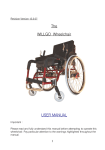
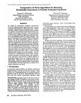
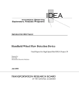
www.kids-quads.co.uk [email protected] 0843 289 0871 LIKE US ON FACEBOOK! QUAD ELECTRIC 36V 500W Models EQ-500 and EQ-501 ASSEMBLY AID To lose the least amount of time possible, follow these instructions in the order indicated. Ask if possible the carton on a table to work at the correct height Open the cardboard box by lifting the lid, and then by removing the hexagon side and finally the angles. Empty the contents of the small cardboard box, and put aside the charger. Open the bags, and take out the tools provided. 1- Unpack and install first the handlebar using the two screws that are there, taking care to avoid that the sons do a turn. 2- Place the central shock absorber as follows: To limit the volume in the carton, the central shock absorber (under the seat) is freed in its lower part and is therefore not operational. For the fit: * Locate, under the seat, just in front of the manufacturer's plate, the two metal tabs in U crossed by a long threaded rod. * Defeats the nut of this rod, and pull it out. * Hold the quad by its framework and press the rear axle: the rear part moves on its axis. * Place the lower part of the shock absorber between the metal tabs by playing on the movement of the rear axle, and center the holes of the tabs with the axis of the shock absorber * Thread the threaded rod through this set, and then tighten. 3- Install the 4 guard-sludge (important to do this before installing the wheels) : Use the 2 screws installed on the tabs to this effect. Observe the direction of the fenders on the photo above (spikes toward the rear and toward the front). The reverse is also possible 4- Install the front wheels. Thread the hubs well to the bottom of the axles, install the nuts which are pre-installed on the axles, without tightening. 5- Install the brake callipers to disk: Drag the disk between the two pads. Do play gently, even the most recalcitrant leave sop! Voltage adjustment cable Then take the allen head screw 6 hollow (BTR) in bag of tools. Slide and then turn the callipers on the disk so as to put the housing of not of bolts in front of the two holes provided for this purpose. Install these 2 screws that will maintain the brake callipers to the framework. Tighten securely. ATTENTION: It happens that in the factory, the brake cables are too tight. Make sure that the pads are not tightened on the disk, and that the wheel turns freely. If applicable, drop a little tension by releasing a little bit of cable using a key of 10 on the lever of the calliper. (See red arrow above) Do the same on both sides. Also check the rear caliper, in the same way. This verification is very important. In effect, the engine of 500W is powerful enough to allow a use even if the brakes are a little tight, and you don't realize. On the other hand, the engine penalty because it is too much, it heats up as any engine too strongly solicited, and eventually burn out. 6- Tighten the wheel nuts and check the operation (wheel free of any impediment). Too tighten these nuts would be to prevent the wheel to rotate freely, and would result in an electricity consumption excessive and even an overheating of the engine. 7- In one of the bags, is located the rear reflector. Install it on the bracket located at the rear of the quad. 8- In the bag containing the user manual, there are two small fuses (including 1 spare fuse). Unscrew the cap marked "fuse" located in the left front of the quad, first install the fuse in the CAP ( important), and then install the cap with its fuse in the housing, and screw. 9- Turn the ignition by turning the key to the right (a detent). The LED battery indicator lights (on the throttle handle) will illuminate. Check the operation of the front light (red button at left hand) 10- Test the proper functioning of the engine and transmission by lifting the rear axle or by installing the machine so that the rear wheels are in the empty, and then operate the throttle handle very gently. Turn off the ignition. 11- Install the bull bars on the front using the BTR screws + nuts which are pre-installed. 12- Check the parallelism of the front axle, correct if necessary with the help of nuts installed to this effect on the steering rods (yellow metal), and tighten. (Attention: each track rod is fitted with a nut to not normal and a nut to not reversed). 13- Make sure all the nuts and bolts of your quad, tighten as much as possible. It is recommended to install the brake-net (blue - medium) on all not of screws, to decrease the risk of loss of tightness due to vibration in use. 14- Turn on the quad at the ground, and test the brakes AV and AR pushing by hand 15- Make sure that all of the wheels are tight (but free! ), as well as the handlebars, handles the accelerator and brake. 16- Turn on charge the batteries with the charger 36V 1600mA provided, to the exclusion of any other, approximately 12 hours before first use. Always connect the charger first on the quad and then the sector CAUTION: Handle the plug of the charger in the taking by the tip. Never pull on the wire, the welds that can release, creating a short circuit or a polarity inversion, fatal for the charger. DO Never approach a metal object of the charging socket of quad! ATTENTION! The manipulation of the charger is reserved exclusively to parents . The charger, said "smart" -smart load -, introduced a red LED during the load, which LED changes to green when charging is complete. There is no risk to leave in charge for many hours even after the end of the load. PARENTAL CONTROL - SLOW SPEED - Restriction The latest models EQ-500 are equipped with a feature of parental control of speed, allowing to limit the peak velocity for the beginner and the more young people. This functionality is realized by a key lock located on the right side of the machine Middle Position (0) : free speed (20 km/h) Position 1 and 2: Gearbox flanged -50% and - 30% REMOTE CONTROL This feature (still present on some of our ads) has been very quickly abandoned, because it cannot operate on an electric model: an electric motor emits an electromagnetic field that the harness of the remote control may not cross that the quad is moving away from a few meters. To date there is no feasible technical solution to this handicap. RECOMMENDATIONS ENGINE The engine can be led to heat in extreme operating conditions. The absence of differential on the quads in general caused a kind of resistance in the turns, that the electrical system includes as a slope or a difficult terrain, and it sends a addition of current generating an overheating. It is recommended to monitor the temperature of the motor if the equipment is used in trotating in circles (the children love it! ), and to background ,during a continuous time greater than 15 minutes. TIRE RECOMMENDATIONS Optimal Inflation: 1.5 bar The quad is shipped with tires cross to big cleats, intended for the all-terrain. The use on asphalt or concrete generates a premature wear of the tires, especially in the case of many turns. In this case, it is recommended to fit tires semi-slicks. The change of tires or air chamber is performed by opening the rim. In effect, these rims are opened in two of that was unscrewed the 3 Allen screws located on the 3 fins of the rim. Very convenient! RECOMMENDATIONS BATTERIES: To maximize the life of your batteries (350 deep cycles in optimal conditions), always replace load at the end of the day, even if the use has been short. The load being deliberately slow for this type of batteries (chargers 1500 or 1600mA, 8 to 10 hours to empty batteries), if you omit a night of charge, you can hardly use the quad the next day. Note: 80% of the load is done in the first half of the charge time, which allows you to catch up a day of forgetfulness ... For the wintering grounds, connect the charger to a programr and adjust a charging time of 20 minutes per week (prog. hebdo) or 5 minutes per day (prog. quot.) to simulate a sort of "floating". This will preserve the life of your batteries. Do not store in places too much exposed to freezing, at the risk of damaging these batteries. Note: drive with the lighthouse lit, it is necessarily fun, but do not forget that this also flushes the battery and reduces the autonomy! Important recommendation : Any electrical system is sensitive to water. Do not use the machine in the rain, on land too wet, snowy or very muddy conditions, or even in case of dense fog. Always store in a dry place and protected. If water penetrates into the variator (e-box), it then happens that short-circuits occur randomly, and one of the phenomena the most feared is a departure uncontrolled machine of powering on and without even operate the accelerator! DANGER! Be careful! If you can not do otherwise, take appropriate measures of protection of the drive against the projections of water and mud, making it as tight as possible. In this case, and to limit the risk, heavily coat of silicone the outputs of son of the drive, and then wrap the drive in a handheld waterproof plastic. You will restrict all this risk, but its elimination is not guaranteed and the vigilance is required. Similarly, never wash the quad to large water (water jet, Kärcher etc. ). The washing should be smooth, by hand, without risk of splashing water. FRAMEWORK FOR THE USE OF THE QUAD - SAFETY This machine is not allowed on public roads. It is recommended to use this quad that on private lands, closed, and with the least possible obstacles. Secure the hazardous locations (ravines, stairs, plans of water, major obstacles, etc. ) Never let a child use this quad without the supervision of an adult. This machine is intended for children of 6 years and more. The parents retain the right to entrust it to younger children, depending on their own appreciation of the capacity of the child. But caution and vigilance are required! Always populate your child of protections, such as headset etc ... VERY IMPORTANT: Always take care to close the exits (portal etc. ) to avoid that by accident or carelessness your child is found on a public road and in the movement MAINTENANCE These machines require little maintenance. However, there is a need to ensure: - Regularly lubricate the chain (ideally with a spray of the type WD40) - Monitor the voltage of the chain. The latter must be tight (but not too). A slack chain causes of derailments, which cause damage to the teeth of the sprocket or the crown, or on the chain itself. Ideally, the tension of the chain must be total (not of "arrow" ). The adjustment of the ideal tension is done by loosening the 4 screws that hold the engine, pushing the engine toward the front by hand (which tends the chain) and then in refixant the engine in the now in a position chain tight. Freeze then this position by tightening the nuts on the front and pulling on the eyelets. Caution: these nuts should not be used to tighten the chain. Only to maintain the chosen position. - Ensure a maximum load of batteries. (Remission in charge after each use, and periodically during the wintering) - Check the tire pressure before each use. Rolling under-inflated can cause the shear of the valve of the air chamber, which requires irretrievably the replacement of the latter. TROUBLESHOOTING - REPAIRS GENERAL APPROACH If the sources of failure are few in number on an electric vehicle, they are sometimes more "vicious" and complicated to detect, would it be only because of our low education in electrical matters and of our habits in terms of thermal engines. To help you determine you-even the causes of a problem and implement the resolution, here is a list of symptoms with their possible sources and our repair advice. A- THE QUAD DOES NOT ADVANCE THE ALL CASE 1 The LEDS of the witness of batteries and the lights do not come on when the ignition is switched: There was a total absence of current in the machine. In this case, check the breaks and false possible contacts in the main supply circuit to the strategic locations: Contact terminals of batteries (6 terminals) Fuse (25 Amps 'rapid', reference F25A250V), or welding the red wires on the output of the fuse box Large white connector fitted with large red and black wires (power supply batteries) Ignition lock (lock barrel " Neiman") and welding the wires below this lock Secondary fuse installed in a black cylinder, present on the red wire of the pair red/blue outgoing of the variator (command key contact) White connector to which directs the pair red/blue (command key contact) NOTE CONCERNING THE FUSE: It happened that by mistake the factory provide fuses too weak or defective on some series. Consequence: Most of the time, the quad works correctly to speed clocked, but the fuse banging of that we released the restriction. Not panic! The resolution of this problem is simple. Explanation: The engine "consumed" 17.8 HAS in fast speed, but less than 10A in slow speed. It is therefore logical that a fuse of less than 20A resisted in slow speed, but the grid when we activated the function fast Resolution of the problem : Install a 25A fuse (reference F25A250V) easy to find and inexpensive, in the traditional commerce (for example among e.g. Halfords) or online (for example, among CONRAD) CASE 2 The LEDS of the witness of batteries and/or the phare will illuminate when the ignition is switched : The machine is powered. Power supply problem engine only. In this case, it is necessary to determine at what level the motor power supply is interrupted, by checking the following points: - Check that the inverter is well on F or R, and not in N (neutral) - Disconnect the connectors from the drive containing the pairs of wires Yellow / Black and test if this solves the problem, in which case the problem comes from the contact breaker circuit breaker safety located in the brake levers. Then check the small switches circuit breaker located on the inside of the brake levers (possibly test with a running-screw end, by pressing on the small contactors plastic) - Check the connection of the son ( 4-wire connector) of the accelerator. - Test the value of the output current of the drive, on the big yellow and blue wires. If the value is zero by accelerating, the drive is faulty. - If this test is positive, test the value of the current on the output of the inverter (red and black wires routed to the engine) by accelerating (take care to put the inverter on F or R). If this test is negative (no current), the problem is located in the inverter that he must change If this test is positive, the problem is located at the engine itself. In this case, verify that the red and black wires are well soldered in the engine. (Requires opening the engine) Note: To determine if the engine is in question, it is sufficient to connect it direct to the terminals of the extreme set of batteries. This simple operation is binary: the engine is running and is therefore not in issue, or the engine is not running and it is not powered (unsoldered terminal on the inside) B - THE QUAD ADVANCED, BUT IT SEEMS TO BE LOW, OR DOES NOT REMAIN POWERFUL THAT VERY LITTLE TIME, OR LACK OF AUTONOMY Make sure that the function slow speed is not enabled, and that the wheels turn freely! In general, a lack of power from either a permanent braking erratically (check the cable tension on the brake calipers! ), either a problem with the charging of batteries. Verify that the LED on the charger remains well red for a long time after use (this means that the load is carried out correctly). The green LED means that nothing is happening. Needless to insist in this case. If the LED on the charger does not pass to the Red franc, it must test the charger before everything, either by plugging it into the sector and by measuring the output voltage (it should be approximately 41V minimum), either in a more empirical manner as follows: 1- Connect the charger ONLY to the sector If the LED is lit green, the charger receives the current If the LED remains off, the charger is faulty input side current and must replace it 2- Connect the charger ONLY on the quad If the LED is green, this means that the charger "communicates" with the machine If the LED does not light up, this means that there is a problem either on the charger (it must be then the Replace), either on the load connection (check all connections downstream of the charging socket up to the variator) 3- Connect the charger to the quad and the sector - If the LED is flashing, there is a default general supply on the quad (very often the main fuse 25A) - If the LED turns red, the load is carried out correctly - If the LED remains green, there is no load The problem can also (more rarely) come from a defective battery. It must measure (after full charge, more rest 1 hour) the voltage of each of the batteries which must indicate ideally 13.25 V (at 12V, a battery is no longer operational). If a battery gives a value of less than and different from the other two, it is defective and must be replaced. We can complete this test with a bulb of car 12V fitted with two wires, and connect on the batteries one by one. A defective battery will give an intensity of light (yellow) much less intense than the other (white). It is appropriate in this case to change the defective battery. A single battery defective corrupted very significantly the capacity of the whole. VARIATOR - CRUISE CONTROL - CONTROLLER This component (see photo below) is the heart of the machine. It is also called "electronic unit" or "cruise control". Its main function is to manage the amount of current sent to the motor according to the movements made on the throttle handle. Secondarily, it concentrates the features annexs, such as the lights, the cut-brake circuits, clamps etc ... If for any reason you need to manipulate the variator, the multiple wires coming out may worry about, but the principle remains simple. It is sufficient to observe the connections as shown on the visual below. Some, such as the stop lamp or the rear light remain free, this quad is not fitted. What you need to know: The function "basic" of this device is to vary the amount of current sent to the engine, depending on the data pulses on the throttle handle. To verify the operation of database, you can disconnect without hesitation all the connectors of features annexs, in not leaving branches that the 4 following elements: - POWER SUPPLY BATTERIES (large red/black) - MOTOR OUTPUT (Large blue/yellow) - IGNITION KEY (small Red/Blue) - Throttle (4-wire connector) This operation allows you to determine if the drive operates, by excluding the interference phenomena induced by the secondary features. The connection as the other connectors, interspersed with tests as the course progresses, allows you to determine what function may be causing problems. We wish you many hours of intense pleasure with this wonderful little machine! www.kids-quads.co.uk [email protected] 0843 289 0871