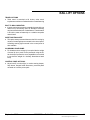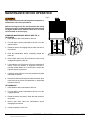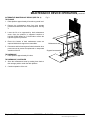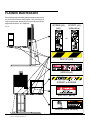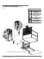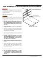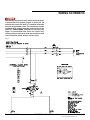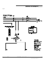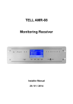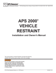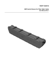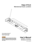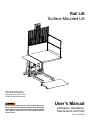
1
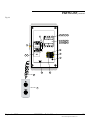
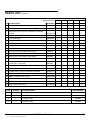
Rail Lift
Surface-Mounted Lift
This manual applies to Rail
Lifts manufactured beginning
September 2013 with the serial
numbers 61089635 and higher.
Do not install, operate or service this product unless you
have read and understand the Safety Practices, Warnings,
Installation and Operating Instructions contained in this
User’s Manual. Failure to do so could result in death or
serious injury.
User’s Manual
Installation, Operations,
Maintenance and Parts
Part No. 6002750E
table of contents
Introduction..................................................................2
Safety Signal Words....................................................2
Safety Practices..........................................................3
Owner’s Responsibilities.............................................4
Installation...................................................................5
Operations...................................................................6
Rail Lift Options...........................................................7
Maintenance Device Operation................................... 8
Troubleshooting.........................................................10
Planned Maintenance................................................12
Mast Guide Roller Bearing Removal and Replacement..... 15
Wiring Schematic......................................................17
Hydraulic Schematic..................................................21
Parts List...................................................................22
Limited Warranty.......................................................27
Distributor Information...............................................28
introduction
Welcome and thank you for choosing this Rail Lift for your material handling applications.
This User’s Manual contains information that you need to safely install and identify parts for the Rail Lift. Please
read and follow this User’s manual when installing the Rail Lift.
safety signal words
You may find safety signal words such as DANGER, WARNING, CAUTION or NOTICE throughout this User’s
Manual. Their use is explained below:
This is the safety alert symbol. It is used
to alert you to potential personal injury
hazards. Obey all safety messages that
follow this symbol to avoid possible death or
injury.
Indicates an imminently hazardous situation which,
if not avoided, will result in death or serious injury.
Indicates a potentially hazardous situation which, if
not avoided may result in minor or moderate injury.
Indicates a potentially hazardous situation which, if
not avoided, could result in death or serious injury.
Notice is used to address practices not related to
personal injury.
2
©2013 4Front Engineered Solutions, Inc.
6002750E — Rail Lift Manual
September 2013
safety practices
INSTALLATION, MAINTENANCE AND SERVICE
Read these safety practices before installing, operating or
servicing the Rail Lift. Failure to follow these safety practices
could result in death or serious injury.
READ AND FOLLOW THE OPERATING INSTRUCTIONS
CONTAINED IN THIS MANUAL BEFORE OPERATING THE
Rail Lift. If you do not understand the instructions, ask your
supervisor to teach you how to use the Rail Lift.
OPERATION
Use restricted to trained operators.
Do not operate the Rail Lift while under the influence of drugs or
alcohol.
Do not stand in the driveway between the Rail Lift and a backing
truck.
Be certain that the truck wheels are chocked, or that the truck
is locked in place by a truck restraining device before loading or
unloading.
Do not use the Rail Lift if it appears to be broken or does not seem
to work properly. Inform your supervisor at once.
Be certain, before doing any maintenance or repair under
the Rail Lift that 1) the maintenance devices are securely in
position and 2) the power is disconnected and properly tagged
or locked off.
All electrical trouble shooting or repair must be done by a
qualified technician and must meet applicable codes.
If it is necessary to trouble shoot inside the control box with
the power on, USE EXTREME CAUTION. Do not place fingers
or uninsulated tools inside the control box. Touching wires or
other parts inside the control box may cause electrical shock,
serious injury or death.
Place barricades on the dock floor around the rail lift and in
the driveway in front of the rail lift while installing, maintaining
or repairing the rail lift.
If you have any questions, contact your supervisor or your local
4Front Engineered Solutions, Inc. distributor for assistance.
Stand clear of moving rail lift.
Keep hands and feet clear of hinges at all times.
Only authorized personnel should perform inspection or
maintenance and service procedures. Unauthorized personnel
attempting maintenance procedures do so at the risk of personal
injury or death.
Do not operate the Rail Lift with equipment, material or people on
the lip.
Always contact the factory for assistance whenever it is perceived
that normal maintenance procedures cannot be followed.
Do not attempt to manually lift the Rail Lift.
Failure to properly adhere to maintenance device operation
procedures is to risk the sudden and uncontrolled descent of
the lift during maintenance or inspection. A falling lift can cause
severe injury or death. Follow the procedures maintenance device
operation instructions EVERY time you plan to reach or enter bodily
beneath the lift to perform service or maintenance – no matter how
momentary that might be.
Ensure that there no obstructions which may interfere with the
operation of the Rail Lift.
If the Rail Lift does not operate correctly using the operating
procedures contained in this manual, DO NOT USE THE Rail Lift.
Call your local 4Front Engineered Solutions, Inc. distributor for
service.
Be certain no equipment, material or people are on or near the Rail
Lift lip before allowing the truck to pull out.
Do not operate the Rail Lift when anyone is underneath it unless
they are securing a safety stand.
Stand clear of moving rail lift.
September 2013
If the maintenance device(s) are damaged or missing, stop
immediately and contact the factory for assistance. The
manufacturer can not foresee, and are not liable for, failure to use
the approved maintenance device(s) and procedures that have
been provided.
Never go under an unsupported platform! To avoid personal injury
or death, always be sure the load has been removed from the
platform and that it has been blocked adequately to prevent shifting
or dropping unexpectedly!
6002750E — Rail Lift Manual
©2013 4Front Engineered Solutions, Inc.
3
safety practices, continued
If NOT operational: The carriage MUST be blocked adequately
from beneath until the time that the lift is made operational again.
If the rail lift cannot be lowered normally, contact the factory for
assistance. If stuck or stalled, the carriage should be secured at its
stuck position before attempting to walk on or under the platform.
All loads must be removed from the Rail Lift platform prior to
engaging the maintenance devices. These devices are designed
to support an unloaded platform only. Failure to remove the load
from the platform prior to blocking could cause the failure of the
maintenance devices and allow the lift to fall unexpectedly.
Do not stand under the platform while setting the maintenance
devices into position. Check the stability of the supports. Make sure
there is no debris under the lower end of the maintenance devices.
No maintenance, or lubrication, shall be performed when the Rail
Lift is in operation.
All Safety devices or guards, handrails shall be in place before
starting equipment for normal operation.
oWNER’S RESPONSIBILITIES
It is the responsibility of the user/purchaser to advise
the manufacturer where deflection may be critical to the
application.
Inspection and Maintenance
The lift shall be inspected and maintained in proper working
order in accordance with the manufacturer’s operating/
maintenance manual and safe operating practices.
Only trained personnel and authorized personnel shall be
permitted to perform maintenance/service operations on the
lift.
Before Operation
Before using the lift, the operator shall have:
• Read and/or have explained, and understood, the
manufacturer’s operating instructions and safety rules.
• Inspected the lift for proper operation and condition.
Any suspect item shall be carefully examined and a
determination made by a qualified person as to whether
it constitutes a hazard. All items not in conformance with
the manufacturer’s specification shall be corrected before
further use of the lift.
Maintenance/Service personnel shall have:
• Read and/or have explained and understood, the
manufacturer’s operating/maintenance manual, and all
safety rules and labels, prior to performing any maintenance/
service operations on the equipment.
During Operation
The lift shall only be used in accordance with the manufacturer’s
operating/maintenance manual.
• Full time unlimited access to the manufacturer’s operating/
maintenance manual.
• Ensure that all safety devices are operational and in
place.
Removal from Service
Any lift not in safe operating condition such as, but not limited
to excessive leakage, missing rollers, pins or fasteners, any
bent or cracked structural members, cut or frayed electric,
hydraulic or air lines, damaged or malfunctioning controls or
safety devices, etc. shall be removed from service until it is
repaired to the original manufacturer’s standards. All repairs
shall be made by qualified personnel in conformance with the
manufacturer’s instructions.
Modifications or Alterations
Modifications or alternations of industrial scissors lifts shall be
made only with written permission of the original manufacturer.
These changes shall be in conformance with all applicable
provisions of this standard and shall be as safe as the
equipment was before modification. These changes shall also
satisfy all safety recommendations of the original equipment
manufacturer for the particular application of the lift.
• Do not overload the lift.
Operators
Only trained personnel and authorized personnel shall be
permitted to operate the lift.
4
©2013 4Front Engineered Solutions, Inc.
6002750E — Rail Lift Manual
September 2013
installation
Fig. 1
To avoid bodily injury read and follow all instructions
before installing, operating or servicing the rail lift.
Before installation, read and follow the Safety Practices
on page 3. Failure to follow these safety practices could
result in death or serious injury. READ AND FOLLOW THE
OPERATION INSTRUCTIONS IN THIS MANUAL BEFORE
OPERATING THE RAIL LIFT. If you do not understand
the instructions, ask your supervisor to teach you how
to use the rail lift.
NOTE:
For Rail Lifts requiring higher than standard travel range,
the deck and A-Frame assemblies may ship unattached
to the main assembly. For these orders, see supplemental
installation sheet for installation details.
1. Upon receipt of rail lift examine all packages for shipping
damages and make claims against carrier for damages.
A-Frame assembly
Deck
assembly
Front
anchor
angle
Mast rail
assembly
Floor mounted
approach ramp
Power unit
cover
Rear anchor
angles
2. Check that floor is flat and level.
3. For units with remote control panel and/or power pack,
install hoses and control wire through conduit in floor.
4. Connect hoses to rail lift cylinder (if applicable).
5. Using a fork lift or crane place the rail lift into the desired
position. Check for any interference with the deck and
the A-frame.
6. If the rail lift does not have an internal power pack, install
power pack as per wiring and hydraulic schematics. Check
for proper motor rotation to avoid pump damage. Check
if all fitting connections are tight. Anchor the power pack
to the floor or mount it on the wall bracket.
Do not install the rail lift anchor bolts into aged or
unsound concrete.
7. The rail lift must be mounted to a concrete pad using six
(6) 5/8" diameter x 4.5" minimum long expansion anchors.
Follow the manufacturer’s recommended installation
instructions for the anchors.
8. Bleed the hydraulic cylinder of air by slowly loosening the
plug until air escapes. As soon as only oil is escaping,
tighten the plug.
September 2013
6002750E — Rail Lift Manual
©2013 4Front Engineered Solutions, Inc.
5
Operations
Before operation, read and follow the Safety Practices
on page 3. Failure to follow these safety practices could
result in death or serious injury. READ AND FOLLOW THE
OPERATION INSTRUCTIONS IN THIS MANUAL BEFORE
OPERATING THE RAIL LIFT. If you do not understand
the instructions, ask your supervisor to teach you how
to use the rail lift.
DESCRIPTION
● The push-button station is on a coil cord or can be fixed
to the wall or to the guard rail
● Optional equipment for the controls are: in motion flashing
light, in motion warning beeper, keyed on/off, Stop button,
and a second push-button station
OPERATION PROCEDURES
GENERAL:
● Cantilever type design
To avoid bodily injury read all instructions before
operating or servicing rail lift.
● Side mounted, direct thrust cylinder
LOADING/UNloading:
● Deck surface of the rail lift must always be level with the
truck bed, building floor or any other surface that goods
are to transferred to or from
● The deck assembly is guided by eight oversized ball
bearing rollers riding on heavy duty elevator mast rail,
providing excellent stability for full capacity loading from
any of the three open sides
DECK:
● Rigid deck consisting of a welded structural steel assembly
with a non-skid checker plate surface
● Beveled toe guards around three sides of the perimeter
HYDRAULICS:
● Direct thrust, extra heavy duty walled cylinder
● Velocity fuse that will lock and fully support the deck
assembly (including the load at rated capacity) in the event
of hose failure
● The cylinder is sealed by a polyetheleyne U-ring, an Hstyle double lip wiper and a high strength low friction wear
ring provide superior rod cleaning and support
● The power pack assembly is comprised of a direct coupled
motor and fully submerged pump, oil reservoir, suction
strainer, solenoid operated lowering valve, pressure relief
valve and a pressure compensated flow control valve.
CONTROLS:
● The control panel is comprised of a NEMA 12 enclosure
(NEMA 4 optional) with a magnetic contactor with thermal
overload motor protection
● Control voltage is 24 VAC (other voltages are optional) is
provided by a transformer in the control panel.
● Push-button station is NEMA 4 rated and consists of two
constant pressure type buttons
6
©2013 4Front Engineered Solutions, Inc.
● Extend the lip before entering the vehicle, retract the lip
when complete.
● The lip is to enter a truck, no less than six inches
● Do not change direction (except in a forward or backward
motion) while on the lip
● The rail lift will accept an unbalanced load, but every effort
should be made to place the center of gravity of the load
over the center of the deck
OPERATION:
Always have the handrails and the safety chains secured
when moving the deck up or down.
Stand clear of moving rail lift.
● To raise or lower the deck assembly, depress and hold
the corresponding button until the deck is at the desired
height, then release the button and the deck will stop
● When the “UP” button is depressed, the motor and pump
start, pushing hydraulic oil from the reservoir through the
lowering valve and into the cylinder
● Pushing the “DOWN” button actuates the solenoid
operated lowering valve, allowing the hydraulic oil to return
to the reservoir along the pressure line and by-pass the
pump
6002750E — Rail Lift Manual
September 2013
rail lift options
TRAVEL OPTIONS
● Table travel is standard at 60 inches, other travel
requirements can be met if ordered at time of manufacturing
BOLT TO WALL MOUNTING
● If space restrictions prevent the standard gusset with rear
anchor set up from being used, an alternative mounting
may be ordered at the time of manufacture. The alternative
is to bolt the mast rail assembly to a suitable composite
material wall.
SAFETY MOTION ALERT
● This option warns personnel whenever the lift is moving by
means of a warning beeper mounted in the control panel.
A flashing warning light mounted in the control panel is
also available.
ALUMINUM LIP AND RAMP
● For situations where a large lip is required but the weight
of a steel lip is too much for the personnel using the lift.
An aluminum lip offers the same capabilities at one third
to one half the weight of a similarly dimensioned steel
ramp.
CONTROL PANEL OPTIONS:
● Keyed on/off, in motion light, in motion warning beeper,
Stop button, flanged fused disconnect, pre-wired panel
mounted on a remote power pack
September 2013
6002750E — Rail Lift Manual
©2013 4Front Engineered Solutions, Inc.
7
maintenance device operation
Fig. 2
Only authorized personnel should perform inspection or
maintenance and service procedures.
Before servicing the rail lift, read and follow the Safety
Practices on page 3, and the Operation instruction section
on page 6 of this User's manual. Failure to do so could
result in death or serious injury.
STANDARD MAINTENANCE DEVICE (See fig. 2)
TO ENGAGE
1. Raise platform above maintenance devices.
2. For both sides, pull the maintenance device out of the
stored location.
3. Rotate the device and engage the pin within the hole of
the mast rail.
4. Push the maintenance device completely though the
mast rail.
5. Ensure both sides have the maintenance device fully
engaged through the mast rail.
6. Lower platform until it comes to rest on the maintenance
device. Once the platform is supported continue to
hold the DOWN button for 5-10 seconds to relieve the
hydraulic system of pressure.
7. Confirm that the platform is securely supported by both
maintenance devices.
8. Disconnect and lock-out/tag out all electrical and/or other
power sources to prevent an unplanned or unexpected
actuation of the lift
TO DISENGAGE
1. Raise platform above maintenance devices.
2. For both sides, pull the maintenance device out of the
engaged position.
3. Rotate the device and store it within the hole located in
the gusset.
4. Ensure both sides have the maintenance device
disengaged and stored.
5. Continue operation of the unit.
8
©2013 4Front Engineered Solutions, Inc.
6002750E — Rail Lift Manual
September 2013
maintenance device operation, continued
ALTERNATIVE MAINTENANCE DEVICE (See fig. 3)
TO ENGAGE
1. Raise platform approximately 4 feet above ground level.
Fig. 3
2. Remove the maintenance struts from their storage
position and rotate them into a vertical position. See Fig
3.
3. Lower the lift to be supported by both maintenance
struts. Once the platform is supported continue to
hold the DOWN button for 5-10 seconds to relieve the
hydraulic system of pressure.
4. Ensure the bottom of both maintenance struts are
captured inside their support box assemblies.
Maintenance strut
5. Disconnect and lock-out/tag out all electrical and/or other
power sources to prevent an unplanned or unexpected
actuation of the lift.
Support box assembly
TO DISENGAGE
1. Raise platform approximately 6 inches.
TO DISENGAGE, continued
2. Store the maintenance struts by rotating them back to
their storage position under the deck platform.
3. Continue operation of the unit.
September 2013
6002750E — Rail Lift Manual
©2013 4Front Engineered Solutions, Inc.
9
troubleshooting
Be certain, before doing any maintenance or repair under
the Rail Lift that 1) the maintenance devices are securely
in position and 2) the power is disconnected and properly
tagged or locked off.
Stand clear of moving rail lift.
NOTE:
This troubleshooting section assumes that the rail lift has
been installed properly and that all electrical and hydraulic
connections have been made correctly. If this is a new
installation or electrical or hydraulic work has been done
on the unit, refer to the appropriate schematics and/or
instructions to verify that the unit is installed correctly.
Before servicing the rail lift, read and follow the Safety
Practices on page 3, and the Operation instruction section
on page 6 of this User's manual. Failure to do so could
result in death or serious injury.
PROBLEM
POSSIBLE CAUSE
SOLUTION
a) Installation connections are not
made.
a) Check to ensure all installation
connections are made.
b) Motor not wired properly.
b)Ensure motor is wired properly.
2. Motor/Pump operate, but rail lift
fails to raise.
a)Pressure relief is set too low.
a)Check to ensure pressure relief is
opened up sufficiently to allow the table
to raise under rated capacity.
3. Rail lift quickly creeps down
while in a raised position.
a) Hydraulic oil is leaking.
a)Ensure that there are no visible
hydraulic oil leaks anywhere in the
system.
b) Hydraulic oil is contaminated.
b)Hydraulic oil must be flushed and
replaced with new clean oil (use
only the oils recommended in the
Maintenance and Lubrication section
on page 13 in this manual.
c)Contaminated hydraulic oil is
preventing check valave from
closing properly.
c)Remove and clean the check valve
and make sure that the seat area in
the valve is not damaged. If the seat
is damaged, call your local 4Front
distributor for the replacement valve.
d)Contaminate hydraulic oil has
damaged seals in valve manifold.
d)Call your local 4Front distributor for
replacement seal kits.
1. Rail lift fails to operate.
10 ©2013 4Front Engineered Solutions, Inc.
6002750E — Rail Lift Manual
September 2013
troubleshooting, continued
PROBLEM
POSSIBLE CAUSE
SOLUTION
4. Rail lift lowers too quickly.
a) Improperly rated flow control.
a) Replace the flow control with a smaller
one (NOTE: for units with adjustable
flow controls you only need to close
valve sufficiently to provide the
desirable down speed.)
5. Motor chatters and rail lift fails
to raise.
a)Contactor not pulling in.
a)Push contactor in manually to confirm.
6. Rail lift fails to lower.
a) Faulty solenoid.
a)Check to ensure solenoid on hydraulic
manifold to confirm.
b) Adjustable flow control is completely
closed.
b)Ensure flow control is not closed
completely.
c) Hydraulic oil is leaking.
c)Check for leaks in the hydraulic system.
If leaks exist, velocity fuse on cylinders
may have tripped. Fix leaks and
repressurize hydraulic system, then
lower.
September 2013
6002750E — Rail Lift Manual
©2013 4Front Engineered Solutions, Inc.
11
planned maintenance
Every 90 days inspect all safety labels and tags to ensure they
are on the rail lift and are easily legible. If any are missing or
require replacement, please call your local authorized 4Front
Engineered Solutions, Inc. distributor.
Fig. 4
6010489 (x2)
(std.)
6010377 (x2)
(alternative)
or
3003147 (A/R)
6003148 (x2)
6008547 or 6008548
6007121 (1 per lift)
6003150 (1 per handrail)
12 ©2013 4Front Engineered Solutions, Inc.
6002750E — Rail Lift Manual
September 2013
planned maintenance, continued
Be certain, before doing any maintenance or repair under
the Rail Lift that 1) the maintenance devices are securely
in position and 2) the power is disconnected and properly
tagged or locked off.
Stand clear of moving rail lift.
Before servicing the rail lift, read and follow the Safety
Practices on page 3, and the Operation instruction section
on page 6 of this User's manual. Failure to do so could
result in death or serious injury.
Use only lubricants referenced below. Improper
lubrication or adjustments may cause operational
problems.
monthly
annually
1. Clean motor/pump assembly.
1. Drain, flush and change oil. Use only Mobil Aero HFA
(49011), Exxon Univis Grade J13, Texaco Aircraft Oil
#1537BB or U.S. Oil Co., Inc. #5606 (low temp.)
2. Clear dust and debris.
3. Keep deck surface clean of all grease, oil and debris.
4.Ensure that all chains, handralis and safety features are
in place and function properly.
2. Remove and clean hydraulic oil pump strainer and reservoir
magnet.
3. Clean inside of reservoir of any debris from old oil.
4. Remove all grease and build-up from mast rail. Re-grease
the mast rail after it is cleaned.
quarterly
1. Grease the mast rail where the bearings make contact. use
general purpose grease.
2. Check mast guide bearings for signs of damage. If any
damage is apparent, replace bearing immediately.
3. Check hoses and fittings for cracks and leaks.
4. Clean accumulated dirt and grease from hoses so that
cracks and leaks can be easily identified.
5.Inspect all safety labels and tags. Replace if necessary.
See page 12 for safety label locations.
6. Check fluid level. Use only Mobil Aero HFA (49011), Exxon
Univis Grade J13, Texaco Aircraft Oil #1537BB or U.S. Oil
Co., Inc. #5606 (low temp.)
September 2013
6002750E — Rail Lift Manual
©2013 4Front Engineered Solutions, Inc.
13
planned maintenance, continued
Fig. 5
Legend
Symbol
Description
Lubricate - oil
Light oil - SAE 30
Lubricate - grease
Molybdenum disulfide
NLGI #2
Cleaning
(Location - frequency)
Visually inspect
(Replace damaged or worn)
Clean debris from under Rail Lift deck assembly
14 ©2013 4Front Engineered Solutions, Inc.
6002750E — Rail Lift Manual
September 2013
Mast Guide Roller Bearing removal and replacement
Cylinder Removal And Replacement
Fig. 6
Be certain, before doing any maintenance or repair under
the Rail Lift that 1) the maintenance devices are securely
in position and 2) the power is disconnected and properly
tagged or locked off.
NOTE: Handrail not shown.
Stand clear of moving rail lift.
Lifting lug position
on back plate (pre-cut)
Before servicing the rail lift, read and follow the Safety
Practices on page 3, and the Operation instruction section
on page 6 of this User's manual. Failure to do so could
result in death or serious injury.
1. Raise deck assembly to approximately two feet above
grade and place supports under the deck assembly. Be
sure that the supports can sufficiently support the weight
of the deck.
2. If using a tow motor or lift truck to lift underneath the
deck go to instruction 7.
Lifting lug position on deck
3. Install load centering eye bolts in the holes provided
in the vertical back plate of the deck assembly and the
deck plate. See Fig. 6 for details.
4. Unbolt the ram of the cylinder from the A-frame assembly.
Once the cylinder is free, clamp or tie the A-frame to the
back of the deck assembly.
5. Disconnect all wires (if applicable) from the deck
assembly. Only tables with options such as perimeter
safety stops or upper travel limit switches should have
wires attached to the deck assembly.
6. Clamp or strap the cylinder to the mast assembly. Ensure
the cylinder will stay vertical once the deck assembly is
removed.
7. With the load centering eye bolts in place on the deck
assembly, vertically raise the deck assembly off the
mast assembly. Place the deck assembly on a solid
level surface to be worked.
8. With the deck assembly removed, now the cylinder can
be removed or worked on.
9. Once the cylinder has been replaced, or the work
is complete, ensure the cylinder is raised back to the
vertical position and is ready to be bolted the A-Frame
assembly.
September 2013
6002750E — Rail Lift Manual
©2013 4Front Engineered Solutions, Inc.
15
Mast Guide Roller Bearing removal and replacement, continued
The deck assembly has a weight imbalance which must be
handled very cautiously when lifting the deck off of the mast
rails. The majority of the weight is on the rail side of the
deck. If using a lift truck or tow motor to remove the deck
assembly it is strongly advised that the deck assembly be
clamped to the forks of the lift truck. When using a crane to
remove the deck assembly be sure to have an experienced
rigger set up the chains or straps before attempting to lift
the deck assembly clear of the rails.
10. Using split ring pliers remove the retaining rings from
the mast guide bearings assemblies. With the retaining
rings removed all the rollers on the deck assembly
should come off with little effort. If a roller is seized on
the stud, be sure not to damage the stud while removing
the bearing.
11. Replace all the old rollers with new rollers and re-install
the retaining rings. (Be sure that the new bearings are
packed with grease.) If a roller bearing replacement kit
was purchased there will be new retaining rings in it.
12. With EXTREME caution lift the deck assembly back onto
the mast assembly. Be sure to use caution when getting
the mast guide bearings started onto the mast assembly
so as not to damage the mast guide bearings.
13. Reconnect all wires that were disconnected to facilitate
deck assembly removal. Re-bolt the A-frame to the
cylinder ram.
14. Remove the load centering eye bolts from the deck
assembly.
15. Restore power to the rail lift and remove supports from
underneath the deck assembly.
16 ©2013 4Front Engineered Solutions, Inc.
6002750E — Rail Lift Manual
September 2013
wiring schematic
Before doing any electrical work, make certain the power
is disconnected and properly tagged or locked off. All
electrical work must be done by a qualified technician
and meet all applicable codes. If it is necessary to make
troubleshooting checks inside the control box with the
power on, USE EXTREME CAUTION. Do not place your
fingers or uninsulated tools inside the control box.
Touching wires or other parts inside the control box could
result in electrical shock, death or serious injury.
Fig. 7
September 2013
6002750E — Rail Lift Manual
©2013 4Front Engineered Solutions, Inc.
17
wiring schematic, continued
Fig. 8
18 ©2013 4Front Engineered Solutions, Inc.
6002750E — Rail Lift Manual
September 2013
wiring schematic, continued
Fig. 9
September 2013
6002750E — Rail Lift Manual
©2013 4Front Engineered Solutions, Inc.
19
wiring schematic, continued
Fig. 10
20 ©2013 4Front Engineered Solutions, Inc.
6002750E — Rail Lift Manual
September 2013
hydraulic schematic
Fig. 11
September 2013
6002750E — Rail Lift Manual
©2013 4Front Engineered Solutions, Inc.
21
parts list
Alternative Maintenance Device
To ensure proper function, durability and safety of the
product, only replacement parts that do not interfere with
the safe, normal operation of the product must be used.
Incorporation of replacement parts or modifications that
weaken the structural integrity of the product, or in a way
alter the product from its normal working condition at the
time of purchase could result in product malfunction,
breakdown, premature wear, death or serious injury.
17
Fig. 12
6
18
19
5
3
16
4
2
1
7
8
15
14
9
20
13
10
12
11
22 ©2013 4Front Engineered Solutions, Inc.
6002750E — Rail Lift Manual
September 2013
parts list, continued
ItemQuantityPart DescriptionPart Number
1
1
Deck Assembly
Consult Factory
2
1
Handrail Assembly
Consult Factory
3
1
A-Frame Assembly, 60" Travel
6010024
4
1
Flat Washer, 3/8"
000-051
5
1
Lock Washer, 3/8"
234301
6
1
Socket Head Cap Screw, 3/8-16 x 1.5" Thread
213454
7
8
Mast Guide Bearing
6010056
8
4
External Retaining Ring, 1-3/8" ID
6010404
9
1
Lift Cylinder, 60" Travel
6010063
10
1
Hydraulic Power Unit, 5HP (208-230/460 VAC), 3 Phase
(For other voltages consult factory)
380382
11
1
Mast Assembly
Consult Factory
12
1
Pin, Lift Cylinder
6008327
13
1
Ramp Assembly
Consult Factory
14
2
Maintenance Stop Assembly
6010252
15
1
Pin, A-Frame
6008328
16
2
Maintenance Strut
6010397
17
4
Clevis Pin, 1/2" Dia x 2-1/4" Long
231506
18
8
Plain Washer, 9/16" ID
234121
19
1
Cotter Pin, 1/8" x 3/4"
231341
20
1
Serial tag
September 2013
6009761
6002750E — Rail Lift Manual
©2013 4Front Engineered Solutions, Inc.
23
parts list, continued
Fig.13
9
8
10
1
7
2
6
3
5
4
ItemQuantityPart DescriptionPart Number
1
1
Filter Breather
033013
2
1
Sight Gauge
033028
3
1
Pressure Gauge, 0-4000 psi (Optional)
033022
4
1
Flow Control Valve
024015
5
1
Elbow, 1/2" M NPT TO #8 M JIC
026076
6
1
Pressure Relief Valve
024165
7
1
Solenoid Coil
024104
8
1
Valve Cartridge
024167
9
1
Velocity Fuse, 10 GPM
313239
10
1
1/2" Hydraulic Hose Assembly, 30" Long
6001899
24 ©2013 4Front Engineered Solutions, Inc.
6002750E — Rail Lift Manual
September 2013
parts list, continued
Fig. 14
18 19 20 21 22
2
4
5
6
7
8
9 10 11 12 13
14
25
24
15 16
23
1
26
3
17
September 2013
6002750E — Rail Lift Manual
©2013 4Front Engineered Solutions, Inc.
25
parts list, continued
Where Used/Quantity
Complete Control Panel 6010401V4 6010401V5 6010401V6 6010401V7 6010401V8
ItemPart DescriptionPart Number
1 Bar, Ground
2
Circuit protector, thermal, 1-pole, 2AMP
3 Sprial cable, 16-3C SJO, 48" retracted, 20' extended,
6" leads
4 Block, Fuse, 2 Pole, Class CC, BC series
5 Fuse, Time Delay
6 Block, Fuse, 2 Pole, Class CC, BC series
7 Fuse, Time Delay
8 Block, Fuse, 2 Pole, Class CC, BC series
9 Fuse, Time Delay
10 Block, Fuse, 2 Pole, Class CC, BC series
11 Fuse, Time Delay
12 Block, Fuse, 2 Pole, Class CC, BC series
13 Fuse, Time Delay
208V/3/60 240V/3/60
380V/3/50
480V/3/60
600V/3/60
1
6000559
1
1
1
1
6000495
1
1
1
1
1
4ZZ-1603-48-SJO
1
1
1
1
1
6000556
1
FNQ-R-6/10
2
6000556
1
FNQ-R-1/2
2
6000556
1
FNQ-R-3/10
2
6000556
1
FNQ-R1/4
2
6000556
1
FNQ-R1/4
2
14 IEC Contactor, Non-reversing, 24VAC, 3-Pole,
+1NO+1NC, 1-15hp/18A
6000467
1
1
1
1
15 Overload Relay, 5.5-8 AMP
6000476
1
1
1
16 Overload Relay, 12-18 AMP
6000478
1
1
17 Pendant Station, 2 NO, 2 Pushbutton, Up/Down
9001BW72Y
1
1
1
1
1
18 XFMR, 208V to 24V, 50VA
9070T50D14
1
19 XFMR, 240/480V to 24V, 50VA
9070T500D2
20 XFMR, 360/380/400V to 24V, 50VA
9070T50D73
21 XFMR, 240/480V to 24V, 50VA
9070T500D2
22 XFMR, 600V to 24V, 50VA
9070T50D16
1
1
1
1
1
ItemQuantityPart DescriptionPart Number
23
1
Surge Supressor
6006852
24
2
End STOP, Screwless, 6mm
6000549
25
7
Terminal, 4 Pole
6006846
26
3
Terminal, 2 Pole
6007888
26 ©2013 4Front Engineered Solutions, Inc.
6002750E — Rail Lift Manual
September 2013
limited warranty
4Front Engineered Solutions, Inc. expressly warrants that this RAIL LIFT will be free from flaws in material and
workmanship under normal use for a period of one (1) year from the earlier of 1) 60 days after the date of initial
shipment by 4Front Engineered Solutions, Inc., or 2) the date of installation of the RAIL LIFT by the original
purchaser, provided the purchaser maintains and operates the RAIL LIFT in accordance with this User’s Manual.
In the event the product proves deficient in material or workmanship, 4Front Engineered Solutions, Inc. will at
its option:
1. Replace the product or the deficient portion thereof without charge to the purchaser; or
2. Alter or repair the product; on site or elsewhere, as 4Front Engineered Solutions, Inc. may deem
advisable, without charge to the purchaser.
This limited warranty stated in the preceding paragraph IS EXCLUSIVE AND IT IS IN LIEU OF ANY OTHER
GUARANTEES AND WARRANTIES, EXPRESS OR IMPLIED. The limited warranty does not cover any
failure caused by improper installation, misapplication, overloading, abuse, negligence, or failure to maintain
and adjust the RAIL LIFT properly. Parts requiring replacement due to damage resulting from vehicle impact,
abuse, or improper operation are not covered by this warranty. 4Front Engineered Solutions, Inc. disclaims any
responsibility or liability for any loss or damage (including, without limitation, direct, indirect or consequential
damages, or lost profits or production time) that results from the use of unauthorized replacement parts or
modification of the RAIL LIFT. 4Front Engineered Solutions, Inc. sole obligation with regard to a RAIL LIFT that
proves to be deficient in material or workmanship shall be as set forth in its standard limited warranty above (i.e.,
4Front Engineered Solutions, Inc. will, at its option, repair or replace the RAIL LIFT or portion thereof, without
charge to the purchaser.).
This limited warranty does not cover any failure caused by improper installation, abuse, negligence, or failure
to properly maintain and adjust the RAIL LIFT. This limited warranty will be void or of no effect if the original
purchaser does not notify 4Front Engineered Solutions, Inc.’s warranty department within ninety (90) days
after the product flaw is discovered. Parts requiring replacement due to damage resulting from vehicle impact,
abuse, or improper operation are not covered by this warranty. 4Front Engineered Solutions, Inc. disclaims any
responsibility or liability for any loss or damage that results from the use of unauthorized replacement parts or
modification of the RAIL LIFT.
THERE ARE NO WARRANTIES, EXPRESS OR IMPLIED, WHICH EXTEND BEYOND THE DESCRIPTION
ON THE FACE HEREOF, AND THERE IS NO WARRANTY OF MERCHANTABILITY OR OF FITNESS FOR A
PARTICULAR PURPOSE.
4Front Engineered Solutions, Inc. warranties extend only to the RAIL LIFT itself.
4Front Engineered Solutions, Inc. DISCLAIMS all warranties, express or implied, responsibility or liability
for loss or damage of any kind associated with the installation or maintenance of the RAIL LIFT, including
any liability for premature product wear, product failure, property damage or bodily injury arising from
improper installation or maintenance of the RAIL LIFT.
September 2013
6002750E — Rail Lift Manual
©2013 4Front Engineered Solutions, Inc.
27
Please direct questions about your Rail Lift to your local distributor or to 4Front Entrematic.
Your local 4Front Engineered Solutions, Inc. distributor is:
Corporate Head Office:
1612 Hutton Dr. Suite 140
Carrollton, TX. 75006
Tel. (972) 466-0707
Fax (972) 323-2661
©2013 4Front Engineered Solutions, Inc.
Part No. 6002750E