1
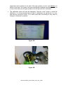
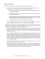
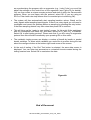
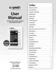
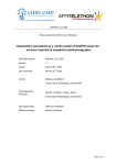
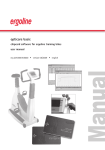
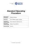
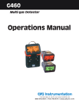
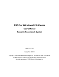
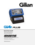
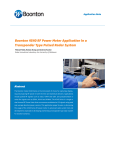
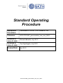
Standard Operating Procedure Equipment / Procedure: ParvoMedics TrueOne® 2400 Metabolic Cart Filename: 2013.0701SOP_parvomedics_true_one_2400 Assessor’s name & date: Reviewer’s name & date: Review Date: Richard Metcalfe, July 2013 Tom Nightingale, July 2013 July 2015 2013.0701SOP_parvomedics_true_one_2400 ParvoMedics TrueOne® 2400 Metabolic Cart The ParvoMedics TrueOne Metabolic Cart allows breath by breath analysis of expired gases. The metabolic cart software can also be synchronised with (or used to control) various ergometers and there are plug-ins available to allow simultaneous collection of heart rate/ECG. This SOP details how to calibrate and set-up the analyser for testing and how to perform various aspects of maintenance. It is presumed that the analyser has been initially set up and is ready to use. For more detailed information relating to the initial set up of the metabolic cart the reader can refer to the user manual. Switch-On and Warm-Up The main on-switch is located at the back of the analyser module (Figure 1A). You must also switch-on the heater which is located at the front of the analyser module (Figure 1B). The system requires a minimum of 30-minutes to warm up prior to calibration – when the green light marked “heater” is off the system is sufficiently warm. Figure 1A Figure 1B Calibration The system calibration includes flow meter calibration, gas analyser calibration, gas analysis, sampling line calibration, and calibration parameter entry. It is recommended that the calibration is performed prior to each test. During whole-day testing protocols it is recommended that calibration is performed once at the start of the morning and once at the start of the afternoon. Gas Analyser Calibration The TrueOne 2400 is set up to allow auto-calibration of the O2 and CO2 analysers. The gas analyser calibration screen can be accessed from the main menu. You will firstly be prompted to enter baseline room temperature, barometric pressure and relative humidity (Figure 2A). These variables can be found on the weather system located next to the monitor. From this menu, also ensure that AutoCal is selected and that the concentrations for the standard gases are correct (a reference sheet with these values is located on the side of the gas cylinder). You will then be prompted to turn on the flow from the standard gas cylinder. To do this, turn the tap valve located on top of the gas cylinder 90° counter clockwise (Figure 2B; denoted by arrow). Always ensure that the pressure regulator (blue 2013.0701SOP_parvomedics_true_one_2400 topped tap valve) located on the side of the gas cylinder is set to 3 psi before you switch on the flow. The system will then automatically calibrate and then prompt you to turn off the flow from the gas cylinder (turn the tap valve 90° clockwise). The calibration report will then be displayed. Click the “save” button to store the calibration. It is recommended that at least 2 calibrations are performed in a row, and that they should be within 1% of each other after accounting for any effect of changes in barometric pressure. Figure 2A Figure 2B 2013.0701SOP_parvomedics_true_one_2400 Flow meter Calibration The flow meter calibration screen can be accessed from the main menu. The flow meter is calibrated using a standard 3L syringe (figure 3A). This is connected to the mixing chamber as shown in Figure 3B. Briefly: 1. Attach the 3L syringe to the Hans Rudolf 2-way non re-breathing valve and then to falconia tubing. 2. Attach the other end of the falconia tubing to the water trap and then to the purple filter’s tapered port. 3. Push the exhale port of the purple filter to the input end of the pneumotach adapter (with 2 O-rings). The exhale port on the purple filter has a slightly larger diameter and has a flat ring at the base of the port. 4. Connect the pneumotach adapter to the heater pneumotach. First the program will prompt you to enter the room temperature, barometric pressure, and relative humidity. Select “sample baseline” to continue. Note: Both the breathing tube and the purple filter must be dry during the flow meter calibration. Otherwise the air will be humidified and expanded in volume when it is passed from the calibration syringe to the pneumotach. The flow meter calibration program first samples the base values of the expiratory and/or inspiratory flows. If the signal is too noisy, when viewed from the graphical screen, you should identify and correct the source of the problem, then click retry to re-sample the signal. You will then be taken to the flow meter calibration processing screen. Here you pass a number of strokes of the 3 L syringe through the system. The first five strokes are detection and flushing strokes (note: it is also recommended to flush a number of strokes through before starting the calibration process) and then there are five calibration strokes. During the calibration you should pass some slow, medium and fast strokes through the system (roughly 50, 100, 150, 200 and 250 l.min-1 is recommended). If the syringe gets stuck or you fail to generate a complete stroke, you can cancel the stroke using the “cancel n.nnnn” button. You will then be taken to the calibration confirmation screen which displays the data relating to the calibration. Click the “save” button to save the new calibration data. It is recommended that the calibration procedure is repeated until the low, high and average volumes are within 1% of the previous calibration. 2013.0701SOP_parvomedics_true_one_2400 Figure 3A Figure 3B VO2/Metabolic Measurements The VO2/Metabolic Measurements menu is located on the main screen of the TrueOne 2400 software. As the program starts, the Patient/Test information screen is displayed. Enter the demographic information about your participant (Participant Code, Age, Height, Weight and Sex). You must also enter a numeric medical record number. Once the test is complete the file will be stored under the information entered in the first and last name boxes. At this point you can also choose to synchronise the program with an ergometer (ergometer must be connected up to the computer to do this) or with the ECG/Heart rate plug in (ECG/Heart rate plug in must be attached prior to selecting this). If you 2013.0701SOP_parvomedics_true_one_2400 are synchronising the program with an ergometer (e.g., Lode Cycle) you must first adjust the settings on the control box of the ergometer (see Figure 3A for details). You can then create a unique exercise protocol and store it within the Parvomedics software. When you are happy with the protocol, select OK (If you are using an ECG or Polar heart rate strap ensure this is connected prior to selecting OK). The system will then automatically start sampling baseline values. Watch out for noisy signals whilst sampling base signals. If there is a noisy signal you will need to investigate and correct the problem before re-sampling by pressing the retry button. If the base sampling detects very little noise then press OK to continue. This will bring up the “ready to start testing” screen. At this point fit the participant with the mouthpiece and nose clip, and allow values for O2 and CO2 to stabilise. Select OK to start testing protocol. Please note that if you are using an ergometer protocol then this will start immediately upon pressing OK on this menu. The metabolic testing screen can display a number of breath by breath or pooled breath variables. To select which variables you would like to monitor during the test select the configure button at the bottom right hand corner of the screen. At the end of testing, if the End Test button is selected, the save data screen is displayed. You can enter test summaries or review/edit events created during the testing session here. Select OK to save/store the data. Figure 4A End of Document 2013.0701SOP_parvomedics_true_one_2400