1
LINC-NIRVANA
–
Generic Infrared Software –
Pattern Constructor
Doc. No.
Short Title
Issue
Date
LN-MPIA-MAN-ICS-008
GEIRS Pattern Constructor
1.295
October 22, 2015
Prepared . .Richard
. . . . . . . . .J.
. . .Mathar
. . . . . . . . . . . . . . . .October
. . . . . . . . .22,
. . . . 2015
.........................
Name
Date
Signature
Approved .Peter
. . . . . . .Bizenberger
...........................................................
Name
Date
Signature
Released . .Martin
. . . . . . . .Kürster
..........................................................
Name
Date
Signature
ii
LN-MPIA-MAN-ICS-008 – GEIRS Pattern Constructor – Issue 1.295
Change Record
Issue
0.041
0.119
Date
2013-02-11
2013-04-29
Sect.
all
Reason/Initiation/Documents/Remarks
created
Version submitted to the ADP
LN-MPIA-MAN-ICS-008 – GEIRS Pattern Constructor – Issue 1.295
iii
Contents
1 OVERVIEW
1.1 Design . .
1.2 Interfaces
1.3 Acronyms
1.4 References
.
.
.
.
.
.
.
.
.
.
.
.
.
.
.
.
.
.
.
.
.
.
.
.
.
.
.
.
.
.
.
.
.
.
.
.
.
.
.
.
.
.
.
.
.
.
.
.
.
.
.
.
.
.
.
.
.
.
.
.
.
.
.
.
.
.
.
.
.
.
.
.
.
.
.
.
.
.
.
.
.
.
.
.
.
.
.
.
.
.
.
.
.
.
.
.
.
.
.
.
.
.
.
.
.
.
.
.
.
.
.
.
.
.
.
.
.
.
.
.
.
.
.
.
.
.
.
.
.
.
.
.
.
.
.
.
.
.
.
.
1
1
1
1
2
2 FILE NAMES
2.1 Start of Computation .
2.2 Conventions . . . . . . .
2.3 Cycle Type Conventions
2.4 Logging . . . . . . . . .
.
.
.
.
.
.
.
.
.
.
.
.
.
.
.
.
.
.
.
.
.
.
.
.
.
.
.
.
.
.
.
.
.
.
.
.
.
.
.
.
.
.
.
.
.
.
.
.
.
.
.
.
.
.
.
.
.
.
.
.
.
.
.
.
.
.
.
.
.
.
.
.
.
.
.
.
.
.
.
.
.
.
.
.
.
.
.
.
.
.
.
.
.
.
.
.
.
.
.
.
.
.
.
.
.
.
.
.
.
.
.
.
.
.
.
.
.
.
.
.
.
.
.
.
.
.
.
.
.
.
.
.
.
.
.
.
3
4
5
5
7
.
.
.
.
.
.
.
.
.
.
.
.
.
.
.
.
.
.
.
.
.
.
.
.
.
.
.
.
3 File Syntax
3.1 Command line expansion . . . . . . . . . . . . . .
3.1.1 White Space and Old-fashioned Comments
3.1.2 Optional Repeat Count . . . . . . . . . . .
3.1.3 Optional Embedded Verbose Comment . .
3.1.4 Optional Embedded Timing Evaluation . .
3.1.5 Further Comment Removal . . . . . . . . .
3.1.6 Do Loop Expansion . . . . . . . . . . . . .
3.2 Expressions . . . . . . . . . . . . . . . . . . . . . .
3.2.1 State Variables . . . . . . . . . . . . . . . .
3.2.2 Automatic Variables . . . . . . . . . . . . .
3.2.3 Constants . . . . . . . . . . . . . . . . . . .
3.2.4 Operators . . . . . . . . . . . . . . . . . . .
3.2.5 Send Expressions . . . . . . . . . . . . . . .
3.2.6 Include Expression . . . . . . . . . . . . . .
.
.
.
.
.
.
.
.
.
.
.
.
.
.
.
.
.
.
.
.
.
.
.
.
.
.
.
.
.
.
.
.
.
.
.
.
.
.
.
.
.
.
.
.
.
.
.
.
.
.
.
.
.
.
.
.
.
.
.
.
.
.
.
.
.
.
.
.
.
.
.
.
.
.
.
.
.
.
.
.
.
.
.
.
.
.
.
.
.
.
.
.
.
.
.
.
.
.
.
.
.
.
.
.
.
.
.
.
.
.
.
.
.
.
.
.
.
.
.
.
.
.
.
.
.
.
.
.
.
.
.
.
.
.
.
.
.
.
.
.
.
.
.
.
.
.
.
.
.
.
.
.
.
.
.
.
.
.
.
.
.
.
.
.
.
.
.
.
.
.
.
.
.
.
.
.
.
.
.
.
.
.
.
.
.
.
.
.
.
.
.
.
.
.
.
.
.
.
.
.
.
.
.
.
.
.
.
.
.
.
.
.
.
.
.
.
.
.
.
.
.
.
.
.
.
.
.
.
.
.
.
.
.
.
.
.
.
.
.
.
.
.
.
.
.
.
.
.
.
.
.
.
.
.
.
.
.
.
.
.
.
.
.
.
.
.
7
7
7
7
8
8
8
8
9
10
13
14
14
15
16
4 TIMING CALCULATIONS
4.1 Aim . . . . . . . . . . . . .
4.2 Timers . . . . . . . . . . . .
4.3 Subcommands . . . . . . .
4.3.1 set . . . . . . . . . .
4.3.2 define . . . . . . . .
4.3.3 state . . . . . . . . .
4.3.4 add . . . . . . . . .
4.3.5 on . . . . . . . . . .
4.3.6 off . . . . . . . . . .
4.4 Functions . . . . . . . . . .
4.4.1 range . . . . . . . .
4.4.2 timeof . . . . . . . .
.
.
.
.
.
.
.
.
.
.
.
.
.
.
.
.
.
.
.
.
.
.
.
.
.
.
.
.
.
.
.
.
.
.
.
.
.
.
.
.
.
.
.
.
.
.
.
.
.
.
.
.
.
.
.
.
.
.
.
.
.
.
.
.
.
.
.
.
.
.
.
.
.
.
.
.
.
.
.
.
.
.
.
.
.
.
.
.
.
.
.
.
.
.
.
.
.
.
.
.
.
.
.
.
.
.
.
.
.
.
.
.
.
.
.
.
.
.
.
.
.
.
.
.
.
.
.
.
.
.
.
.
.
.
.
.
.
.
.
.
.
.
.
.
.
.
.
.
.
.
.
.
.
.
.
.
.
.
.
.
.
.
.
.
.
.
.
.
.
.
.
.
.
.
.
.
.
.
.
.
.
.
.
.
.
.
.
.
.
.
.
.
.
.
.
.
.
.
.
.
.
.
.
.
.
.
.
.
.
.
.
.
.
.
.
.
.
.
.
.
.
.
.
.
.
.
.
.
18
18
19
19
19
19
19
19
20
20
20
20
20
.
.
.
.
.
.
.
.
.
.
.
.
.
.
.
.
.
.
.
.
.
.
.
.
.
.
.
.
.
.
.
.
.
.
.
.
.
.
.
.
.
.
.
.
.
.
.
.
.
.
.
.
.
.
.
.
.
.
.
.
.
.
.
.
.
.
.
.
.
.
.
.
.
.
.
.
.
.
.
.
.
.
.
.
.
.
.
.
.
.
.
.
.
.
.
.
.
.
.
.
.
.
.
.
.
.
.
.
.
.
.
.
.
.
.
.
.
.
.
.
.
.
.
.
.
.
.
.
.
.
.
.
.
.
.
.
.
.
.
.
.
.
.
.
.
.
.
.
.
.
.
.
.
.
.
.
5 DETECTOR WINDOWS
20
5.1 Principles of Operation . . . . . . . . . . . . . . . . . . . . . . . . . . . . . . . . . . . 20
5.2 Example . . . . . . . . . . . . . . . . . . . . . . . . . . . . . . . . . . . . . . . . . . . 21
iv
LN-MPIA-MAN-ICS-008 – GEIRS Pattern Constructor – Issue 1.295
6 PATTERN SCRIPTING
25
6.1 Auto-increment Layer-2 Loops . . . . . . . . . . . . . . . . . . . . . . . . . . . . . . 25
7 TROUBLE-SHOOTING
7.1 Connectivity . . . . . . . . . . . . . .
7.1.1 Linux Driver . . . . . . . . . .
7.1.2 Workstation to ROE . . . . . .
7.1.3 Data Generator (with GEIRS)
.
.
.
.
.
.
.
.
.
.
.
.
.
.
.
.
.
.
.
.
.
.
.
.
.
.
.
.
.
.
.
.
.
.
.
.
.
.
.
.
.
.
.
.
.
.
.
.
.
.
.
.
.
.
.
.
.
.
.
.
.
.
.
.
.
.
.
.
.
.
.
.
.
.
.
.
26
26
26
26
28
File Inclusions . . . . . . . . . . . . . . . . . . . . . .
Timing File Inclusions . . . . . . . . . . . . . . . . .
Subwindow example (full window) . . . . . . . . . .
Subwindow example (detector windows) . . . . . . .
Subwindow example (detector windows) . . . . . . .
Image with open ADC inputs . . . . . . . . . . . . .
Test image by the ROE FPGA simular . . . . . . . .
Hawaii-2 Test image by the ROE data generator . .
Hawaii-2 RG Test image by the ROE data generator
.
.
.
.
.
.
.
.
.
.
.
.
.
.
.
.
.
.
.
.
.
.
.
.
.
.
.
.
.
.
.
.
.
.
.
.
.
.
.
.
.
.
.
.
.
.
.
.
.
.
.
.
.
.
.
.
.
.
.
.
.
.
.
.
.
.
.
.
.
.
.
.
.
.
.
.
.
.
.
.
.
.
.
.
.
.
.
.
.
.
.
.
.
.
.
.
.
.
.
.
.
.
.
.
.
.
.
.
.
.
.
.
.
.
.
.
.
.
.
.
.
.
.
.
.
.
.
.
.
.
.
.
.
.
.
.
.
.
.
.
.
.
.
.
.
.
.
.
.
.
.
.
.
.
.
.
.
.
.
.
.
.
17
18
22
23
24
27
28
29
30
.
.
.
.
.
.
.
.
.
.
.
.
.
.
.
.
.
.
.
.
.
.
.
.
.
.
.
.
List of Figures
1
2
3
4
5
6
7
8
9
LN-MPIA-MAN-ICS-008 – GEIRS Pattern Constructor – Issue 1.295
1
1
OVERVIEW
1.1
Design
The Generic Infrared Software (GEIRS) is a software layer written almost entirely in ANSI-C,
which
• assembles parameter lists and commands received from its own graphical interface or other
supervisor software,
• translates these into the firmware language (“patterns”) of the readout electronics (ROE)
• initializes the readout cycles
• and accumulates the frames received from the ADC’s of the electronics as FITS files on the
local disks or X11 images displayed in the engineering GUI.
This document summarizes the functionality within GEIRS that scans a textual description of
readout patterns and emits the codes (lines) that are converted by the firmware to the sequence of
clocks. We coin the phrase pattern constructor to avoid a name clash with pattern generator, which
is the bottom level (the pattern RAM program) of the firmware actually running the detector pins.
A design choice of the pattern construction is to split functionality into the scanner and the textual
description, assuming that the scanner is a kind of virtual representation of the FPGA’s capabilities
and updated infrequently and co-jointly with that part of the firmware, whereas the patterns are
independently editable by the electronic engineers investigating the characteristics and performance
of the individual chips.
That lead to a simple type of programming (interpreter) language for patterns, the grammar of
which we describe in this manual. (The noun patterns is perhaps misleading here, as the framework
is the current interface to Version 3.1 of MPIA’s readout electronics for Hawaii-2 and Hawaii-2 RG
infrared detectors with two FPGA’s, not any generic driver for a state machinery of arbitrary
detector chips.)
1.2
Interfaces
The document complements the documents on the camera control software [1], ROE [2], readout
patterns [3], and RoCon [4]. To obtain a full list of the commands understood by the FPGA, please
contact the representative electronic engineer of the MPIA.
1.3
Acronyms
ADC
analog-to-digit conversion
ADU
analog-to-digital unit
ANSI
American National Standards Institute http://www.ansi.org
ASCII
American Standard Code for Information Interchange http://http://en.wikipedia.
org/wiki/American_Standard_Code_for_Information_Interchange
2
LN-MPIA-MAN-ICS-008 – GEIRS Pattern Constructor – Issue 1.295
CARMENES Calar Alto High-Resolution Search for M Dwarfs with Exoearths with Near-infrared
and Optical Echelle Spectrographs carmenes.caha.es
FITS
Flexible Image Transport System http://fits.gsfc.nasa.gov
FPGA
Field programmable gate array
GEIRS
Generic Infrared Software
GUI
Graphical User Interface
LINC
LBT Interferometric Camera http://www.mpia-hd.mpg.de/LINC/
LINC-NIRVANA LBT Interferometric Camera and Near-Infrared / Visible Adaptive
Interferometer for Astronomy
LN
liquid nitrogen
LN
LINC-NIRVANA
MPIA
Max-Planck Institut für Astronomie, Heidelberg http://www.mpia.de
MPIfR
Max-Planck Institut für Radioastronomie, Bonn http://www.mpifr-bonn.mpg.de
NIRVANA Near-Infrared / Visible Adaptive Interferometer for Astronomy
OMEGA2000 http://www.caha.es/CAHA/Instruments/O2000/index.html
PANIC
Panoramic Near-Infrared Camera https://panic.iaa.es
PCIe
Peripheral Component Interconnect Express
http://en.wikipedia.org/wiki/PCI_Express
PLX
PLX Technology, Sunnyvale, CA http://www.plxtech.com
RAM
Random Access Memory
RoCon
Readout Controller
ROE
Readout Electronics
SVN
Subversion http://subversion.apache.org
1.4
References
References
[1] C. Storz, LINC-NIRVANA - Infrared Camera Control Software, lN-MPIA-FDR-ICS-005
(6 Jun. 2005).
[2] B. Grimm, U. Mall, LINC-NIRVANA - Readout Electronics for the Science Detector, LNMPIA-FDR-ELEC-001 (21 Jan. 2005).
LN-MPIA-MAN-ICS-008 – GEIRS Pattern Constructor – Issue 1.295
3
[3] V. Naranjo, LINC-NIRVANA - IR Detector Control Pattern, LN-MPIA-DES-ELEC-007
(5 Apr. 2008).
[4] J. R. Ramos, ROCON REad-out Controller Board (Nov. 2009).
URL webdavs://sk1/geirs/roe3MPIA/Roconv3-Draft.pdf
[5] R. J. Mathar, LINC-NIRVANA - Generic Infrared Software, Graphical User Manual, LNMPIA-MAN-ICS-007 (13 Feb. 2013).
URL http://www.mpia.de/~mathar/public/LN-MPIA-MAN-ICS-007.pdf
[6] W. Gaessler, LINC-NIRVANA - Software Style Guide, LN-MPIA-MAN-ICS-001 (02 Aug.
2004).
[7] U. Mall, C. Storz, CARMENES - NIR channel – Readout electronics and software, FDR04C2A. E: in section 2.6.2 the factor 0.5 of the voltage divider is wrong. The actual value for
the CARMENES racks is 0.699. (30 Jan. 2013).
[8] C. Storz, V. Naranjo, U. Mall, J. R. Ramos, P. Bizenberger, J. Panduro, Standard modes
of MPIA’s current H2/H2RG-readout systems, in: 2012 Astronomial Telescopes and Instrumentation, Vol. 8453 of Proc. SPIE, Int. Soc. Optical Engineering, 2012, p. 2E. doi:
10.1117/12.927170.
[9] J. Ramos, Detector-FPGA design v3.1.7, neue Befehle (2 May 2012).
[10] J. R. Ramos, ROCON v3 Upgrade von ROCON v3.0 auf ROCON v3.1 (6 Nov. 2014).
2
FILE NAMES
The main body of the GEIRS, including the text file parser and communicator with the RoCon, is in
the SVN repository https://svn.mpia.de/gulli/geirs/src, whereas the patterns are in repositories on a per-instrument basis, in particular https://svn.mpia.de/gulli/geirs/nirvana/ for
LINC-NIRVANA. In consequence,
• adding new features to the parser or any kind of extensions to the syntax described below,
and occasionally also modifications of constants requires changes in the C-source code of the
current branch plus recompilation;
• adding new patterns, modifications on the shuffling, insertion/changes of patterns and their
orders and so on can usually be done on the spot by editing the textual representation in the
INFO subdirectory of the layout. These files are interpreted, not compiled.
• different SVN version numbers appear, one for the common GEIRS source code and one for
the pattern files of a particular instrument (here: for the LINC-NIRVANA).
Permanent changes anyway require uploading the modifications to SVN.
The relevant pattern files are in $CAMHOME/INFO, the subdirectory appropriate for the instrument,
here $CAMHOME/INFO/Nirvana. The SVN copy is obtained for example with
cd $CAMHOME
mkdir -p INFO/Nirvana
4
LN-MPIA-MAN-ICS-008 – GEIRS Pattern Constructor – Issue 1.295
cd INFO/Nirvana
svn checkout https://svn.mpia.de/gulli/geirs/nirvana/trunk .
This subject is more deeply covered by the first chapter (installation) of the associated basic manual
[5].
If the name of an instrument is changed—for example from Lucifer to Luci1 and from Luci to
Luci2—, one would
1. add an alias to the enumeration, the new name and the new extension in camtypes.h,
2. create a new subdirectory in $CAMINFO reflecting the new name, copy all files of the old
directory to the new one, and switch suffixes in the new INFO/instru with a script similar to
#!/bin/bash
# Move all files with suffix .lucifer to files with suffix .luci1
for fil in *.lucifer ; do
targ=${fil%".lucifer"}.luci1 ;
mv $fil $targ
done
3. introduce the new CAMERA variable in the scripts/GENERIC and optionally add a new link.
Some overview of which exposure times have been calculated is kept in $CAMHOME/log/itime*.
Detailed accounts of how these intervals accumulate appear in $CAMTMP/timing*.log. Software
style and file layout are completely unaware of any LN-specific documented guidelines [6].
2.1
Start of Computation
The entry point in the file system where the construction of the pattern starts is roe init chch.extension,
where
• ch denotes the one or two digits of the number of ADC channels in use. For multi-chip cameras
like PANIC or CARMENES, this is the number of channels dedicated to each individual chip,
• and where .extension is .nirvana in our case.
The scanner steers the selection of parameters that build tables in the FPGA program by computing
file names from variables that are known to the main parser. The selection of read-out modes and
window modes, for example, triggers inclusion of a subset of files in the INFO directory with the
mechanism detailed later and illustrated in Figure 1. Conceptionally, all supported readout modes
are implied by the files in one SVN revision of the associated repository.
The effect of scanning the pattern files is immediate. In particular each send command (Section
3.2.5) visited in a file interacts with the real hardware of the ROE. If GEIRS had been started
with the ROE declared in an offline state, a form of software simulation within GEIRS takes over.
This software simulator is essentially the only method for a dry-run syntax check of the pattern
and timing files; it will detect problems with ill-defined variables, missing parentheses and other
typographic errors, but it also is absolutely optimistic assuming that all commands to the ROE
that are constructed would be returning no errors from the firmware.
LN-MPIA-MAN-ICS-008 – GEIRS Pattern Constructor – Issue 1.295
5
The scanner interprets the pattern files line-by-line. So
• the contents of files that are not included (by the mechanism of chapter 3.2.6) does not matter.
• errors in commands sent to the ROE may leave the (partially initialized) ROE in some fuzzy
state.
For that reason, the communication with the firmware may use a relaxed set of timeouts (see Section
3.2.5). With that concept of early setup, the read command will start an exposure with minimum
time overhead. (The delay of this exposure still depends on which type of idle-(break)-mode is
currently executed by the firmware.)
2.2
Conventions
The files named biases with commands in the 900 range appear to contain, well, voltage biases
and register settings for the infrared chip [4, 7].
Files starting roe* are top level commands issued by GEIRS at certain strategic times (power-up,
shutdown, re-init,. . . ).
Files starting lay* and pat* emit lines for the up to five intermediate layers of the FPGA program
and the lowest (RAM) layer. The name pat indicates these are the definitions of the actual patterns
beyond the administrative other layers.
The table* files are tables that cross through one or more layers.
incl* are sequences in lower levels meant not to be started as a self-sustained program but to be
included by other files.
The timing* files contain basically sets of embedded timing commands, see Section 4.
There is no formal difference in the handling of these files. Any file can incorporate other files
with the include mechanism (Section 3.2.6). The variable syntax is the same. Lines within the
timing* files that use the timing calculator still need to start with the special comment #!timing=
to trigger some calculation. In that respect, it is a mere convention and is not syntactically required
that the construction of the patterns and the timing calculation are kept in separate files.
2.3
Cycle Type Conventions
After an underscore, the standard acronyms of readout modes are often a substring of the file names
[8]. The acronyms and the representation in the FITS headers are: The two chop modes are only
of historical interest with MAX/UKIRT. This list is basically fixed if the file name is computed
by expanding the ctype variable (see Section 3.2). The cycle types listed above are a hard-coded
list in the current source code, cameratypes.h, and depend on which version of GEIRS is used.
The suffix of the file names is instrument specific, here .nirvana, and otherwise .blue, .black,
.max128, .max256, .omegap, .omegac, .omega2k, .roe1, .roe2, .midi, .pyramir, .linc, .fft,
.roe3, .panic, .luci, .lucifer, .carmenes, .sc. Lists with aspects like these contain many
entries which may be obsolete for a decade or more and may certainly change in the future.
The read modi (cycle types) offered by the software for a specific instrument (camera) are hardcoded in the function supported ctype in nutil.c as in Table 1.
6
LN-MPIA-MAN-ICS-008 – GEIRS Pattern Constructor – Issue 1.295
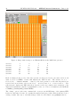
Table 1: Supported GEIRS readout modes. The checked combinations are admitted by the software.
Allowance is restricted to the privileged users if the check mark appears in parentheses.
short
FITS
LN,PANIC
CARMENES,Luci
rrr
reset.read.read
X
X
rrrr
res.res.read.read
rr
reset.read
multi
multiple.endpoints
ramp
ramp.reads
speckle
speckle.reads
subarray
subarray.rrr
dc
DC.read
scr
single.corr.read
dcr
double.corr.read
mcr
multi.corr.read
oramp
ramp.reads
orrr
reset.read.read
omult
multiple.endpoints
X
X
rr-mpia
fast-reset.read
X
X
rrr-mpia
fast-reset-read.read
X
X
rrr-fmpia
intrlvd-ln-rd-rst-rd
subrrr-mpia
subarray.fastrrr
subrrr-fmpia subarray.fullrrr
rr-irl
reset.read
rrr-irl
reset.read.read
subrrr-irl
subarray.rrr
submer
sub.multiple.endpoints
subsrr
sub.sample.ramp.read
mer
multiple.endpoints
o2mer
multiple.endpoints
srr
sample.ramp.read
X
X
srre
sample.ramp.read.embreset
X
fcr
fast-rst-double.corr.read
lir
line.interlaced.read
X
X
fullmpia
intrlvd-ln-rd-rst-rd
o2scr
o2.single.corr.read
X
X
o2dcr
o2.double.corr.read
X
X
msr
multiple.successive.read
X
X
spr
single.pixel.read
rlr
reset.level.read
X
X
sfr
single.frame.read
X
X
fecr
fast.end-corr-dcr.read
X
X
limer
line.interlaced.multiple.endpoint.read
X
X
lisrr
line.interlaced.sample.ramp.read
X
X
limsr
line.interlaced.multiple.successive.read X
X
licntsr
line.interl.continuous.sampling.read
X
X
cntsr
continuous.sampling.read
X
X
LN-MPIA-MAN-ICS-008 – GEIRS Pattern Constructor – Issue 1.295
7
Based on criteria which are not related to software, only the lir with electronic multi-sampling
set to 4 and rrr are considered the readout modes for standard LN scientific operations.
2.4
Logging
The stream of commands to and responses from the ROE are logged as described in the base
manual [5]. One may watch updates of this file with a GEIRS GUI, which opens a X-terminal
executing tail -f on this log file [5].
One may change the log level individually for the object files camsend, camset and camtiming by
sending a log command to the interpreter shell—see the command list in the appendix of the GUI
manual [5].
To aid debugging, the contents of the entries in levels 6 down to level 1 and the “pattern” level
most recently downloaded to the ROE may be summarized with the command geirs roeDump.pl
in the devel subdirectory. The command is called with a single argument which is the instrument
to be debugged, for example
geirs_roeDump.pl Luci1
or
geirs_roeDump.pl Panic
and prints the content of $CAMHOME/log/roe ...log by eliminating duplicates.
3
File Syntax
3.1
Command line expansion
Interpretation of the command line is done with the following steps executed in the order documented.
3.1.1
White Space and Old-fashioned Comments
The lines in the files contain comments that are first stripped off the contents:
• Letters/numbers/strings starting at and including the semicolon (;) up to the end of the line
are discarded. This way of delimiting comments with the semicolon is obsolete.
• White space then remaining at the start and/or end of the line is also removed.
3.1.2
Optional Repeat Count
Lines that start with the asterisk (*) followed by an (optionally parenthetically nested) integer
expression followed by a second asterisk and more tokens have the expression between the asterisks
evaluated. This *...* expression signals a count for a loop over the rest of the line.
8
LN-MPIA-MAN-ICS-008 – GEIRS Pattern Constructor – Issue 1.295
• If the expression evaluates to a negative value, an error is raised. The remainder of the file is
not parsed or executed.
• If the expression evaluates to zero, this line is effectively not executed, independent of what
remains in the line.
• if the expression evaluates to a number ≥ 1, a repeat count applies to the rest of the line.
If the line does not start with a *...* expression, the repeat count is implicitly set to 1.
If the expression in *...* evaluates to 1 or 0, i.e., a boolean value, the semantics is equivalent to
the singly branched if-statement of other programming languages.
3.1.3
Optional Embedded Verbose Comment
If the remaining line now starts either
#!verbose=on
or
#!verbose=off
the log level is increased or decreased.
3.1.4
1
Optional Embedded Timing Evaluation
If the remaining line contains an “embedded” comment of the form
#!timing=
(without spaces), the followup timing expression is evaluated (see Section 4).
3.1.5
Further Comment Removal
Any characters/numbers/strings starting at a hash (sharp) mark (#) up to the end of the line are
discarded. (At that point the embedded comments of the two formats mentioned in Sections 3.1.3
and 3.1.4 are wiped.) Note that removal of the (old) comments started with the semicolon or with
the sharp cannot be masked by means known from other scripting or programming languages.
Another round of removing white space at the start and end of the line follows. If the residual line
is empty, the execution of this line is effectively done. This faith happens to most of the simple
free-form comment lines which start just with the hash.
3.1.6
Do Loop Expansion
If the command contains a substring of the form do (the white space after the do is mandatory),
it is verified whether a repeat count had been found before the do. The repeat count has either the
1
C. Storz 2013-05-16: Verbose activates output to the shell.
LN-MPIA-MAN-ICS-008 – GEIRS Pattern Constructor – Issue 1.295
9
computed *...* format described above, including the implicitly defined 1, or is a variable name.
If that check fails, an error is raised.
The first part of the expression after the do is a blank-separated loop variable—a name without $
or &. The name is to be unique (as a syntax check of correctly nested loops) and reappears in the
list of known variables (see Section 3.2.1).
The next expression after the name of the loop variable evaluates to an integer, the loop counter;
the remainder of the line is executed as often as requested by this counter. (This is a loop executed
within the GEIRS scanner simplifying the task of sending similar blocks of FPGA program lines
to the ROE. It is not related to the loops in levels 2 and up of the Control-FPGA.)
Note that variables in the “body” (after) the do accumulate any changes while looping. (They are
passed by name, not by value.) So their values in any of the loops is whatever has been substituted
(left over) by the previous loop.
Note also that the (optional) repeat count at the start of the line and the loop counter are two
independent multipliers. The total number of executions of the expression after the loop counter
is the product of both.
Do-loops may be nested, so the “body” of the do-loop may contain another do-loop. The nesting
is currently limited to 10 levels (see MAXCMDLOOPINFO in camintf.h). This containment typically
occurs indirectly by an include command which calls another do-loop.
3.2
Expressions
An expression is evaluated by the following rules:
• Nested parentheses (....(....)..(..).) are evaluated right to left. Improperly nested
parentheses and empty parentheses () result in errors.
• Assignments have the format
variable:
value
or
variable=value
and are also evaluated right to left (if there are more than one).
The first format is an assignment which assumes that the variable has not been used before
and is generally used to initialize auto-variables (see Section 3.2.2). A check that the variable
is not known up to that point of the flow of the scanner is done; this helps for example to
detect cyclic inclusions of files. (This can be switched off by undefining the preprocessor
variable DEBUG AUTOVAR REASSIGN in camintf.c). 2
The second format with the = sign replaces the value of the variable on the left hand side by
the value on the right hand side.
• State variables (indicated by a leading $) and auto-variables (indicated by a leading &) are
substituted in the order right-to-left. The range of the name may be explicitly bound by curly
parentheses of the format ${...} or &{....}. This allows “computed” variable names or file
2
C. Storz 2013-05-16: The first format results in an empty string, where the second assignment is delivering the
result to the interpreter
10
LN-MPIA-MAN-ICS-008 – GEIRS Pattern Constructor – Issue 1.295
names of the format ${....&{...}...}, for example. This is similar to constructs known in
Tcl, Unice’s shells,. . .
The curly parentheses are not needed in general, because names are limited by the next white
space, the next operator symbol (Section 3.2.4) or the next question mark ?. So &huu*...
takes the variable huu and not a variable huu*, for example.
3.2.1
State Variables
Definitions (values) of state variables are first searched in files roe variables.<extension> in
$CAMINFO, which is roe variables.nirvana here. The file contains zero or more lines with the
following format:
• The embedded comment #!verbose=on or #!verbose=off at the start of a line switches
verbosity on or off.
• Leading white space is ignored. Everything starting with # or ; up to the end of a line is also
ignored (comments). Leftover white space at the start or end of the line is also stripped off.
• After this comment reduction step, a matching line has the format of the variable name
(starting with the $), one ore more blanks, and the substitutional value. (In between there
is neither the colon nor the equal sign.)
Variable names are case sensitive. The full name in the file must match, so if searching for
abeq1, neither the value in a line starting $abeq nor a line starting $abeq1o is taken.
The substitutional value may still contain embedded blanks. The main application of this
feature (expressions with interlaced blanks) is to assemble the command and argument lines
sent to the ROE by simply writing these side by side, separated by blanks, on the same line.
• If more than one line in the file matches the name, the first match sets the value—in a
principle of early return from the file.
If the variable has not been found in the file, the second search place is the list of loop variables
kept in scanner’s state, introduced with a do (Section 3.1.6).
If the variable is not a loop variable either, a third fixed list is build into the source code:
• $canSrre Boolean value (0 or 1). The 1 indicates that the current ROE and detector type
support the srre mode, which means that the FPGA on the current ROE supports the
commands related to the uploading of the associated serial registers of the chip and that the
current chip type is the Hawaii-2 RG. The main use of this variable is to skip inclus’ion of
the pattern files multi* according to the recipe
*($canSrre)*include multi_win_res_init
• $chans Number of detector channels (per chip if there is an array/mosaic)
• $chlines Number of lines (slow direction) in each detector channel.
• $chpixels Number of pixels (fast direction) in each detector channel.
LN-MPIA-MAN-ICS-008 – GEIRS Pattern Constructor – Issue 1.295
11
• $cmdtablesize This was only used for the ROE2 generation and used for a double-scan
evaluation of the command table.
• $crep Cycle repetition count. See the crep parameter of the roe command [5]. For the lir
and fullmpia cycle types, this is the “clean” count, not counting the first frame that will be
discarded by the GEIRS process after being received.
• $crep1m4lir The same meaning as crep but including a work-around for a lir macro frame
count problem. Apparently this was only used for OMEGA2000.
• $ctype The code name of the current cycle type; one of the list in Section 2.3.
• $dif idle Boolean value which indicates whether the idle-type differs from the read-withoutconversion type.
• $ems Electronic multi-sampling count. 1, 2 or 4. See the ems parameter of the roe command
[5].
• $eof Boolean value which indicates with a value of 1 (indicating true) that the end-ofconversion datum in the frames is generated by the ROE, otherwise with a value of 0 that
these bytes are not in the data stream.
• $eop Boolean flag: if true, the end-of-pattern trigger in the ROE firmware is activated. See
the eop parameter of the roe command [5].
• $ffprot Boolean value (0 or 1), indicating full-frame persistence protection with subwindows
should be activated. See the ffprot parameter of the roe command [5].
• $fpatall The summatory (total) number of fast windows in all pattern windows in the slow
direction.
• $fpatsi The number of fast pattern windows in the slow pattern window number number i.
• $gap Remaining time up to the integration time seconds or microseconds?
parameter of the roe command [5].
See the gap
• $idle The method to leave the idle mode, either the string break or the string wait.
• $irmult For the correlated reads, the number of frames. Since there are at least two frames
needed for the reduction, the range of the variable is from 2 upwards.
• $isH2RG Indicates with a value of 1 that this is a Hawaii-2 RG, and with a value of 0 that
this is any other type (Hawaii-2, Hawaii-1, . . . ).
• $isAIav Indicates with a value of 1 that the auto-increment command of the ROE3 (version
3.1.7 and newer) is available, else 0. The command is special in the sense that it takes three
integer parameters—start, skip (which may be negative) and maximum—and increments
the original start value by the skip value (up to the maximum) each time the command is
revisited [9]. Besides the program counter at each of the FPGA levels this is apparently the
only memory build into the FPGA program.
• $itime cnti with i = 1, 2, 3 or 4.
12
LN-MPIA-MAN-ICS-008 – GEIRS Pattern Constructor – Issue 1.295
• $lskiptime Line skip time in integer units of the base clock of this skip time. See the lskip
parameter of the roe command, the output of status roe and the lskp entry of the GUI
for the current base clock [5]. A-posteriori the value of the base clock (in nanoseconds) can
be found marked with type=geirsROE LSKIP/3 in the debug*.log file.
• $ndet Is the number of chips in the camera, 4 for PANIC, 2 for CARMENES, 1 for all other
instruments planned or in use.
• $oflwprot Boolean: 1 if the overflow protection against persistence effects should be activated, 0 if it should be off (deactivated). See the oflwprot parameter of the roe command
[5]. This variable and ffprot are just flags from the point of view of the main software
which can be set or reset. What they actually mean is entirely in the hands of the pattern
definitions.
• $preadtime Pixel read time in units of the base clock of this read time. See the pread
parameter of the roe command, the output of status roe and the value after the prd label
in the GUI [5]. A-posteriori the value of the base clock (in nanoseconds) can be found
searching for type=geirsROE PREAD/1 in the debug*.log file.
• $pskiptime Pixel skip time in integer units of the base clock of this skip time. See the pskip
parameter of the roe command, the output of status roe and the value of pskp in the
GUI [5]. A-posteriori the value of the base clock (in nanoseconds) can be found marked with
type=geirsROE PSKIP/2 in the debug*.log file.
• $ptime Pixel time in integer units of the base clock of this time. See the ptime parameter of
the roe command [5].
• $pxllns Appears to be the number of lines in the pattern RAM table spent for one conversion
(including the time of the electronic or software multisampling). See the pxllns parameter
of the roe command [5].
• $readf This is an abbreviation to mean the same as readf1s1 (see below).
• $readfX sN with two integers X ≥ 1 and N ≥ 1 is the number of reads (pixels) to cover the
fast hardware window number X along the slow direction.3
• $reads This is an abbreviation to mean the same as reads1 (see below).
• $readsi with i ≥ 1 is the number of reads (clocks) to cover the hardware window number X
along the slow direction.
• $rocv RoCon FPGA version of ROE3. This integer variable is assigned to 2 for version 2, to
3 for version 3, and to 4 for version 3.1.
• $shortlines Is a power of two between 1 and the value of chlines (the latter is the default).
It indicates that the readout (and associated resets) is not performed sequentially along the
slow direction of the quadrant or detector, but that the number of pixels along that direction
is divided into blocks of length shortlines. The readout-reset cycle is first done on the first
block, then on the second and so on, such that the integration time on each pixel is “short”,
that is one half, a quarter, one eights and so on compared to the standard integration time.
To first order, this shuffling and subdivision leaves the cycle time unaffected.
3
C. Storz 2013-05-16: pixels of slow window N
LN-MPIA-MAN-ICS-008 – GEIRS Pattern Constructor – Issue 1.295
13
• $skipf This is an abbreviation to mean the same as skipf1s1 (see below).
• $skipfX sN with two integers X ≥ 1 and N ≥ 1 is the number of reads (clocks) to skip to
reach the fast hardware window number X along the slow direction.4
• $skips This is an abbreviation to mean the same as skips1 (see below).
• $skipsi with integer i ≥ 1 is the count of skips to reach subwindow i in the fast direction.
• $spat Number of hardware window patterns defined in the slow clocking direction.
• $subrep Sum of the skipped and coadded number of frames that altogether result in one
co-added frame to be saved. A value of 5, for example, could mean that each quintuple of 5
frames generated by the ROE are coadded to one image, or that in a dash-dot-pattern of 2 : 3
(or 1 : 4, 3 : 2, 4 : 1 . . . ) two frames are skipped then 3 coadded to form an image, then two
skipped and 3 coadded to form the next, cyclically repeated. This was probably only used
for MIDI.
• $subwin The string subwin or the empty string. Useful to dispatch inclusion of files that
use or do not use subwindows.
• $SWms Software multi-sampling count. See the swms parameter of the roe command [5]. In
practise always 1.
• $synccrep
• $tbl idle Integer representation of the idle type according to the enumeration in cameratypes.h:
0 ReadWoConv
1 Reset
2 Rlr
3 Lir
• $time
• $useSHI Boolean flag: if 1 (representing true), the variable shortlines is used, otherwise (if
0) the variable is not meaningful.
New variables are added (others hardly ever removed by the principle designer’s programming
conventions) as new detector modes are implemented.
3.2.2
Automatic Variables
Automatic variables have no value beyond the computation of the (timing) pattern. The meaning
of automatic is that the variable’s value does not extend beyond the pattern evaluation and that
it is created and initialized with the colon : assignment, see Section 3.2.
There are two subtypes of automatic variables. The variables with a name starting with capital-A
are volatile and the others are resident.
4
C. Storz: 2013-05-16: of slow window N
14
LN-MPIA-MAN-ICS-008 – GEIRS Pattern Constructor – Issue 1.295
• The volatile variables start to be known after their first assignment and are lost (forgotten)
when the UNIX/Linux process that creates them terminates.
• The resident variables are held in the shared memory data base and keep/update their values
as long as the shared memory manager (of that user for that instrument) is alive, which
means, between startup and shutdown of GEIRS. Sending data to the RoCon is optimized to
compare new requests by the command interface—originating from the GUI’s or the command
interpreter/shell or external command calls through the cmdServer—with the most recent
values maintained in the data base; if the requested parameter values are the same as those
memorized, they are not forwarded to the ROE.
A maximum of 100 volatile automatic variables may be in use (variable MAXAUTOVARINFO in
camintf.c) and a maximum of 1200 resident automatic variables (variable MAXGLOBALVARINFO
in camera.h).
3.2.3
Constants
• String constants are delimited by tic marks ’.....’.
• Integers are written in the usual ASCII representation. If the representation is in base 16,
the expression must start with 0x in front of the digits. (There is no equivalent typography
for base-8 that one might expect from other languages.)
• Floating point constants are symbolized by having a dot . in their value. The precision of
the expression is defined by the highest precision of the individual values, that is, the largest
numbers of digits after the dots of any of the values that are combined with the operators
(Section 3.2.4). The precision (number of digits in the sense of the f-format of C) of the
substituted (resulting) value is set to that precision of the expression.
3.2.4
Operators
Operators look like single-letter abbreviated operators of C/C++/csh and pattern matching operations in perl, awk etc:
1. The plus + initializes addition.
2. The dash - is the minus sign or operator. Caution: In cases without leading white space like
abc-de, the dash is part of the name. To obtain the minus-operator, insert a blank in front
of the minus.
3. The star * is the multiplication operator. The strict difference to the star in the loop count,
Section 3.1.2, is that there is no variable/value to the left of the loop count. Therefore the
notation is unambiguous with respect to the meaning of the *-symbol.
4. The slash / is the division operator.
5. The percent % is the remainder (modulo) operator.
6. The less-than < is the comparison operator.
7. The greater-than > is another comparison operator.
LN-MPIA-MAN-ICS-008 – GEIRS Pattern Constructor – Issue 1.295
15
8. The bang ! is the comparison on not equal. (Think of the C/C++/Java style binary
operator.) This is a binary operator with two operands, one to the left and one to the right.
9. The tilde ~ is the comparison on equal, opposite to the !.
The four comparison operators are also applicable to strings with the standard strncmp(3) library definition (where shorter strings are less than longer strings, and strings of equal length are
compared left-to-right based on position of the letters in the ASCII table).
The 9 operators are evaluated left-to-right; there is no standard priority like multiplication and
division ranking above addition and subtractions. If order matters, an additional inclusion of the
higher order operation in (...) ensures that the calculations are performed in the desired order.
The value of a comparison operator becomes either 1 (representing the boolean value true) or 0
(false). The standard way building an integer-based de-Morgan Algebra starts from the 4 comparison operators:
• To construct an expression which is true if a and b are true, the values of a and b are
multiplied to form a new expression.
• To build an expression which is true if a or b or both are true, the values of a and b can be
added and compared to zero to form a new expression.
• To build an expression which is true if exactly one of a or b is true, the values of a and b can
be compared with the not-equal operator to form the combined expression.
If either the left or right operand of one of these operators is a hex-based integer, the result will
also be written in that base with a 0x in front.
The arithmetics is generally done in double precision mode, but if neither the left nor the right
operand are floating point values, the result is converted back to integer after the calculation. This
implies that the / is the round-to-minus-infinity integer division if the two operands are integers.
There are no trigonometric, exponential, logarithmic, number-theoretic or other functions or operations dealing with lists, vector or similar set-constructions recognized by this calculator.
3.2.5
Send Expressions
A command is forwarded to the ROE if an optional expression with zero, one or two exclamation
marks ! is followed by an expression with one or two question marks. Each line of that type
must—after substituation of any parentheses—represent a valid command to the microprocessor
interface as specified in the RoCon drafted manual [4].
• ? Send the following expression and wait for an answer.
• !? Send the following expression, wait for an answer, and do not check the answer.
• !n!? Send the following expression, wait for an answer, re-try this up to n times, and do not
check the answer.
• !-n!? Send the following expression, wait for an answer, retry this up to n times, and check
the answer.
16
LN-MPIA-MAN-ICS-008 – GEIRS Pattern Constructor – Issue 1.295
The timeout in these 4 formats may be changed by using two—not one—question marks with a
timeout (an integer, in units of seconds) in between: $seconds$.
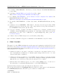
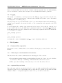
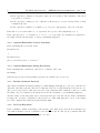
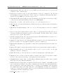
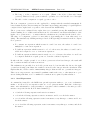
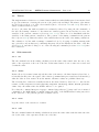
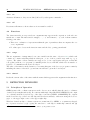
3.2.6
Include Expression
The expression of the form include followed by white space and a filename—without the instrument
suffix—starts to scan that file from the top and returns to the file of the include that started this
discursion. The log files (Section 2.4) write Start and End marks when entering and exiting the
files.
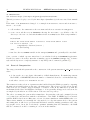
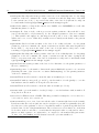
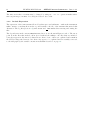
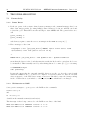
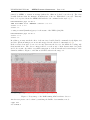
The dependencies in the current INFO/Nirvana directory are shown in Figures 1 and 2. The arrow
point from the files that include others (noted without the suffix) to the files that are included.
Some files appear in disconnected clusters from others. Some of these are orphaned and remain in
the SVN for unspecified reasons, but others only appear to be orphaned and are actually connected
to the full graph by the variable extension mechanism described on page 10.
LN-MPIA-MAN-ICS-008 – GEIRS Pattern Constructor – Issue 1.295
test_subwin
test_extensions
17
incl_subwin
file(&Autovar
roe_run
table_rlr_subwin
table_rlr_lnR$subwin
table_mcramp
irmult_mcramp
table_combi_ctype
table_combi
size_qlay1
size_qlay2
roe_qlayer_size
size_qlay3
size_qlay4
size_qlay5
size_qpat
incl_combi
table_$(&curCtype)${subwin}
table_msr_embed
table_embed_ctype
incl_mcramp_embed_part
table_embed
table_mcramp_embed
incl_mcramp_ff_skip_rdpart
table_o2scr_subwin
table_scr_frmR_subwin
incl_slow_RnoConv_subwin
roe_rdmode_msr_embed_msr
table_dcr_frmRrr_subwin
incl_slow_noConvER_subwin
table_rrr_subwin
table_dcr_slwfrmRrr_subwin
incl_slow_rdER_subwin
incl_slow_rdnoER_subwin
table_fecr_subwin
table_dcr_rrlnR_subwin
table_o2dcr_subwin
table_dcr_fstfrmRrr_subwin
incl_slow_Res_subwin
table_msr_subwin
table_mcramp_subwin
lay3_irmult_mcramp_subwin
table_srr_subwin
table_ucr_ItimeRd_subwin
incl_slow_rd_subwin
table_cntsr_subwin
table_dcr_lnR_subwin
table_sfr_subwin
append_dcr_lnR_subwin
table_rrr-mpia_subwin
incl_slow_rr_subwin
incl_fast_PIXnoConv_subwin
incl_fast_rd_subwin
table_mer_subwin
table_rlr_lnR_subwin
table_spr_subwin
table_rr-mpia_subwin
table_licntsr_subwin
table_scr_lnR_subwin
incl_slow_RdRd_subwin
table_limer_subwin
incl_slow_lir_subwin
table_limsr_subwin
incl_slow_rNoRd_subwin
table_lisrr_subwin
incl_slow_RnoPIX_subwin
table_lir_subwin
incl_rlr_mainstream_part
incl_fast_RnoPIX_subwin
itime_stream3
incl_nondestr_mainstream_part
incl_slow_${s3ctype}_subwin
table_mcramp_embed_s3s2ratio
roe_rdmode_msr_embed_lir
roe_rdmode_debug
roe_rdmode_fecr
roe_rdmode_licntsr
incl_rlr_ff_skip_rdpart
table_mcramp_embed_noAI
table_mcramp_embed_lir
roe_rdmode_limer
roe_rdmode_lir
incl_rlr_ff_skip_rdpart_noAI
itime_embed
incl_nondestr_ff_skip_rdpart
incl_rlr_embedstreams_part
roe_rdmode_limsr
roe_rdmode_lisrr
incl_slow_${s2ctype}_subwin
incl_nondestr_ff_skip_rdpart_noAI
incl_rlr_embedstreams_part_noAI
roe_crep
incl_nondestr_embedstreams_part
incl_nondestr_embedstreams_part_noAI
roe_rdmode_mer
roe_rdmode_msr
roe_rdmode_o2dcr
roe_rdmode_o2scr
roe_idletype
rdmode
roe_rdmode_rlr
roe_rdmode_rr-mpia
proc_crep
table_${ctype}$subwin
timing_${ctype}$subwin
roe_itime
lay3_dcr_1st_rrlnR
roe_rdmode_rrr
roe_rdmode_rrr-mpia
lay3_dcr_rrlnR
roe_rdmode_sfr
lay3_short_dcr_1st_rrlnR
roe_rdmode_spr
table_fecr
lay3_short_dcr_rrlnR
lay3_cntsr
roe_rdmode_srr
lay3_rlr_lnR
roe_rdmode_test_rr-mpia
roe_rdmode_cntsr
table_${ctype}_subwin
lay3_scr_lnR
roe_itime_subwin
table_cntsr
lay3_sfr_ItimefflnNoR
lay3_srr
lay3_ff_lnRes
lay3_lir
init_lay3
lay3_dcr_fstfrmRrr
table_o2dcr
lay3_dcr_short_fstfrmRrr
lay3_dcr_lnRrr
table_rrr-mpia
lay3_short_dcr_lnRrr
biases
lay3_dcr_short_slwfrmRrr
table_rrr
lay3_dcr_slwfrmRrr
table_licntsr
lay3_licntsr
table_limer
lay3_limer
table_mer
lay3_mer
table_msr
lay3_irmult_mcramp
table_srr
table_debug
lay2_aui_short_dcr_rrlnR
init_lay2_aui
lay2_aui_short_dcr_1st_rrlnR
pat_ems_ConvOnly_H2
table_test_rr-mpia
pat_ems_PIXnoConv_H2
lay2_aui_short_dcr_fstfrmRrr
pat_ems_PIXwConv_H2
init_pat
lay2_aui_short_dcr_lnRrr
pat_ems_NoPIXnoConv_H2
roe_ptime
lay2_aui_short_dcr_slwfrmRrr
pat_ems_NoPIXnoConv_H2RG
table_pxl_sampling
init_pat_H2
pat_ems_PIXnoConv_H2RG
table_limsr
init_pat_H2RG
pat_ems_PIXwConv_H2RG
table_lisrr
lay3_irmult_liramp
pat_ems_ConvOnly_H2RG
init_lay1
itime_pat
init_H2
roe_init_ch32
init_H2RG
roe_init_ch4
init_adc_ch$chans
roe_init
init_lay4
init_lay5
init_lay6
init_simram$simram
roe_rdmode_$ctype
biases_and_registers
Figure 1: Mutual inclusion of files by other (non-timing) files.
18
LN-MPIA-MAN-ICS-008 – GEIRS Pattern Constructor – Issue 1.295
timing_fecr
table_fecr
timing_o2scr
timing_o2scr_subwin
timing_rr-mpia
timing_rr-mpia_subwin
timing_rrr-mpia_subwin
timing_rrr_subwin
timing_sfr
timing_sfr_subwin
timing_spr
timing_srr
timing_srr_subwin
timing_test_rr-mpia
timing_cntsr_subwin
timing_debug
timing_dummy
timing_fecr_subwin
itime_pat
timing_licntsr_subwin
timing_limer
timing_limer_subwin
timing_limsr
timing_limsr_subwin
timing_lir
timing_lir_subwin
timing_lisrr
timing_lisrr_subwin
timing_mer
timing_mer_subwin
timing_msr
timing_msr_subwin
timing_o2dcr_subwin
timing_o2dcr
table_o2dcr
timing_rrr
table_rrr
timing_rrr-mpia
table_rrr-mpia
Figure 2: Mutual inclusion of files by timing files.
4
4.1
TIMING CALCULATIONS
Aim
The timing calculations accumulate the clock cycles of the stages of (virtually) running a pattern.
In that sense they are informative and do not generate ROE command lists, but serve to predict
the total time spent in readout cycles depending on chip capabilities, windowing, readout modes,
ROE base clock frequencies etc. If there is demand of fixing the duration of the readout cycles,
such calculation also allows to defer an integration time by calculation of the overhead times as a
function of all these parameters.
In summary, this part of the GEIRS software predicts how much time will be spent on which
stages/levels of the ROE’s pattern generator, but the actual timing is independent of these calculations. The result of summing up all the loops and steps down to the lowest (RAM) level of the
pattern program in the associated FPGA of the ROE over one frame of the exposure appears as
the cycle time of the control GUI [5].
LN-MPIA-MAN-ICS-008 – GEIRS Pattern Constructor – Issue 1.295
4.2
19
Timers
The implementation defines a set of named timers which are individually started, incremented and
stopped as a function of tracing the actions of the pixel reads and skips. The names of the timers
are used without the $ or & of the other variables (those of Sections 3.2.1 and 3.2.2). The unit of
values of timers is microseconds.
Access to the timer list with its variables is exclusively achieved by using the subcommands of
the embedded timing comment. So the timers are entities separated from, but have access to the
variables of the pattern constructor (Sections 3.2.1, 3.2.2). There is a close handshake with the
variables of the main pattern construction. The position of the timing commands in the pattern
files of (Section 3.1.4) defines the values of the variables that are the basis of the timing evaluations.
The evaluation of a line with a timing= command is done by dropping everything starting with
any optional second # character (comments) that may follow the initial # at the start of the line
(Section 3.1.3), and then looking for one of the following subcommands (Sections 4.3.1–4.3.6) after
the =-character.
4.3
4.3.1
Subcommands
set
The subcommand set in the timing calculation sets the timer value named after the set to the
value of the expression of the rest of the line. If the named timer does not exist, it is created and
obtains the value.
4.3.2
define
Define followed by a timer’s name uploads the value of the timer to the shared memory data base, so
it basically lets know the other parts of the software (command interpreter and data read-interface)
what the value is. If no name follows the define, all timer’s values are published that way.
The following list of timers is actually known in the shared memory data base, i.e., fixed in the
scanner: ctime, creptime, roitime, gapitime, skiptime, shortflag, irmult, Nreads, patitime,
itime. Any other names after the define will not be recognized.
Note that the command interpreter’s pipe command (Appendix in [5]) may send bare formatted
commands to the ROE which potentially change the state of the ROE without leaving any traces
in the data base or the pattern generator’s variable tables.
4.3.3
state
Logs the values of the current set of timers.
4.3.4
add
The subcommand add in the timing calculation increases the timer value with the name after the
set by the value of the expression in the rest of the line.
20
LN-MPIA-MAN-ICS-008 – GEIRS Pattern Constructor – Issue 1.295
4.3.5
on
Activates all timers so they are modified/effected by subsequent commands.
4.3.6
5
off
Deactivates all timers so their values are frozen until re-enabled.
4.4
Functions
Two functions with one respectively two arguments may appear in the expression of the subcommands set or add. The functions are range(...,...) and timeof(...); each of them returns a
floating point value.
• There is no evaluation of expressions within the pair of parentheses that encompasses the one
or two arguments!
• No white space between the function name and the left, opening parenthesis!
4.4.1
range
The two arguments of range must be two auto-variables in the sense of Section 3.2.2, which each
contain one common substring which is either pat, or one of the 6 possible layi with 1 ≤ i ≤ 6,
or proc. The values of these variables are supposed to be two non-negative integers, a start and
a stop (line) address of a “program” (command) in the detector FPGA, which refer as usual to a
sequence of commands in the next lower layer.
The value of the function is the duration of executing this part of the detector program, recursively
including the times of the sub-loops and auto-increment loops in the lower layers.
4.4.2
timeof
Reads the current value of the timer with the name which appears as the argument in the function.
5
DETECTOR WINDOWS
5.1
Principles of Operation
GEIRS spans a 2D coordinate system across the detector area, which defines the user’s coordinates
of windows (rectangular subareas). For cameras with single chips (like LINC-NIRVANA), the origin
of coordinates is in the lower left edge of the chip, for mosaics (PANIC, CARMENES) the origin is
in the lower left edge of the lower left chip and stretches seemlessly—without noticing the detector
gaps—to the upper right corner of the upper right chip.
Windows defined in this coordinate system are transformed by GEIRS to a symmetry-adapted
set of pattern windows by (i) copying the windows to each chip for multi-chip cameras and (ii)
5
C. Storz 2013-05-16: Kann auch fuer einzelne Timer on/off genutzt werden.
LN-MPIA-MAN-ICS-008 – GEIRS Pattern Constructor – Issue 1.295
21
replicating the windows in each quadrant for detectors with quadrants (Hawaii-1, Hawaii-2), and
(iii) clamping the windows into a single channel (Detector channels and ADC channels match for all
current implementations which aims at maximum parallelization of readout and ADC operation or
shortest possible integration times, respectively.) This implements a sychronous timing of read-out
and data transfer, defines the interface relevant to the pattern construction, and settles the speed
(exposure time, frame rate).
Finally there is a set of detector windows which is obtained by (i) replicating the pattern windows
across all channels and (ii) merging/glueing (where possible) windows that are direct neighbours.
This happens within GEIRS upon receipt of the data and does not effect the patterns. Mapping
the union of the pixels of these detector windows data back onto the user’s coordinate system may
yield a very rugged, complicated and fragmented tiling with holes and/or non-connected patches.
The most efficient way of saving these data would be an option to deliver a FITS file with a single
frame defined by a bounding box around all of these, filling holes with the BLANK value. (Most
efficient means that all available ADC values are saved; disk space consumption is not optimized
because holes are also covered.) The actual methodology implemented in GEIRS removes all pixels
data that are not in any of the user’s windows and stores only the user’s windows into the FITS
files.
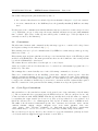
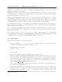
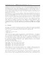
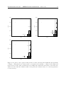
5.2
Example
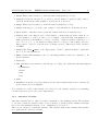
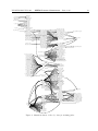
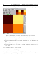
An example of the subwindow parameters is given next to illustrate the parameters readfXsN
and skipfXsN of Section 3.2.1. We assume that the user has requested a single software window
with a lower left pixel at [700,900] and an upper right pixel at [1209,989] with
> subwin clear
> subwin SW 1 700 900 510 90
> subwin auto on
which is the solid rectangle crossing from quadrant II to quadrant III in Figure 3. For Hawaii-2
detectors (including LINC-NIRVANA), GEIRS adds symmetric copies to the other quadrants by
three times 90 degree rotation around the center of the detector such that each quadrant is covered
by the same number and shape of windows. The principle of symmetry is: if a pixel must be read
in one channel, the equivalent pixels in all the other 31 channels must also be read. This adds
the dashed windows in Figure 3, which may overlap. (This step is absent for detectors without
quadrants like the Hawaii-2RG.)
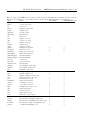
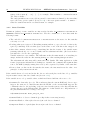
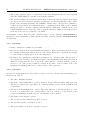
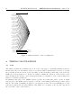
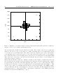
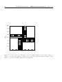
The output of the status subwin then shows
subwin
subwin
subwin
subwin
SWwin: id=1 xs=700 ys=900 xw=510 yw=90
DETwin: id=0 fs=36 ss=990 fw=90 sw=35
DETwin: id=1 fs=36 ss=700 fw=90 sw=200
DETwin: id=2 fs=1 ss=900 fw=128 sw=90
which is illustrated for the pattern windows numbered 0 to 2 in Figure 4. This represents a 128wide slice through one (any one) quadrant along any of the 8 channels after the pixels in use are
copied 8-fold to all channels: second application of the principle of symmetry.
In the first quadrant, the fast direction is along the x axis, the slow direction along the y axis.
The geometries of the three non-overlapping windows are characterized by a starting pixel index
in the slow direction (ss), a starting pixel index in the fast direction (fs), a width along the slow
22
LN-MPIA-MAN-ICS-008 – GEIRS Pattern Constructor – Issue 1.295
2048
1792
I
IV
II
III
1536
y [px]
1280
1024
768
512
256
0
0
256
512
768
1024
x [px]
1280
1536
1792
2048
Figure 3: Example of a software window requested (horizontal quadrangle) and three symmetryadapted, rotated copies (dashed quadrangles) added.
direction (sw), and a width along the fast direction (fw). The clocking of the detector pushes the
charges to the detector edge, so the pixels of y = 2048 of quadrant I are received first and the pixels
of y = 1025 are received last in time. The values of the skip variables refer to that order in time,
so in quadrant I ss is counted from the top edge, and fs from the right border of each channel.
(Note that this relation between timing and geometry is not necessarly fixed for the Hawaii-2RG
chips, where the order along both directions, the fast and the slow, may be reverted/flipped by
appropriate setting of registers.)
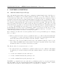
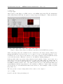
Slicing this intermediate result into channel boundaries (each channel of width 128 in the fast
direction) and 8-fold replication along the fast direction fuses the windows with id=2 into a single
long horizontal bar across the entire first quadrant, and creates 8 copies of id=0 and id=1. These
17 windows are effectively “executed” in parallel in the other quadrants, which gives Figure 5. This
pattern of an overlay of rectangular windows that are sent from the ROE to the GEIRS software
on the workstation can also be investigated by selection of the show all RO information in the
fourth menu at the top of the display GUI [5]. An example of this feature of the GEIRS engineering
GUI has been shown in a SPIE article [8, fig. 5].
LN-MPIA-MAN-ICS-008 – GEIRS Pattern Constructor – Issue 1.295
2048
23
2048
I
1792
I
1792
0: ss=990
1536
1280
y [px]
y [px]
1: ss=700
1536
1: fs=36
1280
1: sw=200
1: fw=90
0: sw=35
1024
0
256
512
768
0: fw=90
0: fs=36
1024
x [px]
1024
0
256
512
768
1024
x [px]
2048
I
1792
y [px]
2: ss=900
1536
1280
2: sw=90
2: fw=128
1024
0
256
512
x [px]
768
1024
Figure 4: Geometry of the 3 pattern windows labeled id=0, id=1 and id=2 within the first quadrant
of Figure 3. Each window is characterized by a s(tart) and a w(idth) coordinate in the f(ast) and
s(low) direction. The window with index 2 is actually wider than 128, but in these cases where the
window is wider than the channel width of 128 pixels, the width is reduced to 128 in preparation
for the next step.
24
LN-MPIA-MAN-ICS-008 – GEIRS Pattern Constructor – Issue 1.295
2048
1792
I
IV
II
III
1536
y [px]
1280
1024
768
512
256
0
0
256
512
768
1024
x [px]
1280
1536
1792
2048
Figure 5: 4 × 17 = 68 detector windows reported by status subwin for the software window of
Figure 3. 8 copies of the windows of Figure 4 are created along the fast direction, where 8 is the
number of detector and ADC channels in each quadrant.
LN-MPIA-MAN-ICS-008 – GEIRS Pattern Constructor – Issue 1.295
6
25
PATTERN SCRIPTING
6.1
Auto-increment Layer-2 Loops
Since early 2010 the functionality of the layer-2 commands (command number 713) of the DetectorFPGA has been enhanced by two further parameters after the loop count. These are called increment and limit. If the value of increment is zero, executing the layer-2 program (by a layer-3
program) executes the layer-1 program as many times as specified by the loop parameter. Otherwise the increment is a signed integer that works like an arithmetic increment/decrement of the
loop variable by that amount after each execution of the layer-2 program. The first call of the
layer-2 program by the layer-3 program executes the layer-1 program loop times, the second call
excutes the layer-1 program loop+increment times, the third call loop+2× increment times and
so on, up to and including the case where loop+l×increment≤limit for increment> 0 and up to
and including the case where loop-l × |increment| ≥limit for increment< 0. Once the loop count
has surpassed the limit, it is reset to the loop parameter—with the same type of crescendo of loop
counts following in further executions of the layer-2 program.
We see that the case where the increment parameter is zero is not special with respect to changing
the loop counter.
• If the increment is non-zero and loop equals limit, the loop counter is effectively always the
loop parameter—because at the first executation of the layer-2 program always is that value,
and because already the next excuation resets the “hidden” counter to loop.
• If the sign of the increment differs from the sign of the arithmetic difference limit-loop, the
reset condition is fulfilled after each execution of the layer-2 program, and the loop counter
is always the same for execution of the layer-1 program.
The effective offset l× increment is reset to l = 0 if
1. the entry in layer-2 is overwritten in conjunction with a new 713 command—this implies
stopping the process and resetting it and is just a further instance of the reset cause further
down,
2. or as the 730 command resets the entire layer,
3. or as the command 740 starts the pattern process
4. or as the command 741 stops the pattern process
The EXIT-loop command 742 does not alter the loop arithmetics of the loop, increment and limits.
One may think of the auto-increment functionality as some hidden but global “static” variable
which remembers its history without taking notice of the EXIT-loop command.
26
LN-MPIA-MAN-ICS-008 – GEIRS Pattern Constructor – Issue 1.295
7
TROUBLE-SHOOTING
7.1
Connectivity
7.1.1
Linux Driver
1. If the two parts of the software, shared memory manager and command manager have been
shut down inapproprietly (by using kill(1)), shared memory blocks are still allocated and
sockets left open. This will let another attempt to start GEIRS fail. The general advice is to
call
geirs_cleanup -t
geirs_cleanup -v
and then try again to start the server; cleanup is in the PATH as set up in [5].
2. Error messages of the form
libplxmpia.c:233: [plx_find_device] ERROR) Error in Plx device found
(u=2/chan=0): ffff ffff [bus ff slot ff fn ff]
or
ERROR Error: plx_find_device: ’PLX ApiError 516 - ApiNoActiveDriver’
mean that the driver for the board that interfaces with the RoCon fiber optics has died or not
been installed. This is usually cured by either fixing this at boot time (see [5]) or executing
cd $CAMHOME/scripts
sudo plxstartup
It may also mean that the currently installed driver is not the one (not the version) with
which the GEIRS source code has been compiled. A typical scenario for this error is that
after an upgrade of the PLX driver start instrument old fails because the binary residing
in the old bin* directory is linked to a library in /usr/src which has been changed.
7.1.2
Workstation to ROE
Some generic attempts to open a port to the ROE are the commands
telnet server port
and
nc -z server port
detailed in the manuals telnet(1) and nc(1).
The first sign of then being connected to the ROE are two lines of the kind
INFO Seen ROE3 rocon ’DETFPGA’ version ’3 1 7 5’
INFO Seen ROE3 rocon ’ADCFPGA’ version ’3 0 2 2’
LN-MPIA-MAN-ICS-008 – GEIRS Pattern Constructor – Issue 1.295
27
printed by GEIRS to stdout at startup (unless the offline mode had been selected). The Seen
actually indicates that the firmware identifications of the two FPGA had been read. This may
later on be repeated from the GEIRS shell with the 550 command in the style of [4]
Nirvanamathar> pipe 33 550 0
INFO Seen ROE3 rocon ’ADCFPGA’ version ’3 0 2 2’
33 550 0 2 3 0 2 2
33 550 0 1
or using a neutral (harmless) query for the status of the LED’s (510) like
Nirvanamathar> pipe 33 510 0
33 510 0 2 0
33 510 0 1
In addition one may watch the effect of the associated enable/disable commands for the lights, 508
and 509. (Their meaning is erroneous and swapped in the current documentation [10]).
If the readout electronics does not receive any data from the detector, the ADCs are reading only
their internal noise. The detector images then do not show any of their characteristic bad pixels
and look very smooth, with a very shallow impression of the horizontal and vertical stripes of the
channels, similar to Figure 6, and almost all ADU values in the range ±1.
Figure 6: Noisy image of the ROE running ADC’s without detector.
Another test picture can be taken by switching the ROE to data simulator mode
ctype sfr
roe simadc 1
28
LN-MPIA-MAN-ICS-008 – GEIRS Pattern Constructor – Issue 1.295
and comparing the frame with Figure 7. This shows actually 32 different values (which appear as
Figure 7: Image from the ROE FPGA data simulator with a single-frame-read.
only 4 different values caused by the contrast) with the following values [7]:
• Quadrant I, channels 1 to 8 (right to left): 256, 273, 290, 307, 324, 341, 358, 375.
• Quadrant II, channels 9 to 16 (top to bottom): 4744, 4761, 4778, 4795, 4812, 4829, 4846,
4863.
• Quadrant III, channels 17 to 24 (left to right): 9216, 9233, 9250, 9276, 9284, 9301, 9318, 9335
• Quadrant IV, channels 25 to 32 (bottom to top): 14472, 14489, 14506, 14523, 14540, 14557,
14574, 14591.
If fiber channels were swapped, only zeros appear.
7.1.3
Data Generator (with GEIRS)
Another basic test of the connectivity between the PCIe board and the workstation is to generate
a single full-frame image with the data generator [7],
LN-MPIA-MAN-ICS-008 – GEIRS Pattern Constructor – Issue 1.295
29
> ctype sfr
> rotype dgen
which ought look like Figure 8 in FITS readers or the GEIRS engineering GUI. For instruments
with a single Hawaii-2 RG chip, the pattern of stripes appears as in Figure 9. This tests that the
Figure 8: Image with 8 stripes per Hawaii-2 quadrant from the ROE data generator.
PCIe board plugged into the workstation can be addressed by the driver software. This is more
fundamental than the check in Section 7.1.2, because it does not reach further than the “local”
workstation. It does not involve any interface between the workstation and the ROE and should
even work if fibers and/or Ethernet connection to the ROE are missing/unplugged.
If this (possibly with a repeat factor larger than 1) is saved with the “dump” option, save -d, a
binary file is created in the standard save-directory with a file suffix .dump. It contains either 16
bit per pixel or 32 bit per pixel (the latter if coadding was involved) in the native byte order of
the GEIRS workstation, in the “raw” order defined by the read-order of the individual ADC’s and
sequentialization with the data transfer to the workstation. (This is 2 × 2048 × 2048 =8,388,608
bytes in the file for each full Nirvana frame in the sfr mode, and a multiple of this for repeats
larger than one.)
The data generator creates a ramp with a 32-bit counter, so the output of
od -i *.dump
should be the list of integers starting at 1:
30
LN-MPIA-MAN-ICS-008 – GEIRS Pattern Constructor – Issue 1.295
Figure 9: Image with 32 stripes on a Hawaii2 RG from the ROE data generator.
0000000
0000020
0000040
0000060
0000100
0000120
0000140
..
1
5
9
13
17
21
25
2
6
10
14
18
22
26
3
7
11
15
19
23
27
4
8
12
16
20
24
28
Each 32 datum (double word) of the data generator is intepreted as two successive 16-bit words
when received by GEIRS, because this matches the ADC bit size. The stream of 1, 2, 3, . . .
65535, 65536, . . . 4194303, 4194304, . . . issued by the data generator for the first 4k pixels is interpreted in low-word-first order as 1, 0, 2, 0, 3, . . . 0, 65535, 0, 0, 1, 1, 1, . . . 65535, 63, 0, 64, . . .. The
pattern in the display and FITS files then depends on the type, number and orientation of the
chips in the instrument, plus the sequentialization of the one or more 32 channels by the ROE and
re-shuffling (demultiplixing) within GEIRS.
The “dump” option of the save command also creates a raw ASCII dump of the primary FITS
header in a file named *.info. It contains the standard 80 bytes per line without any line feeds or
carriage returns. One way to read this strange format for a file named, say, genDump4.info is
LN-MPIA-MAN-ICS-008 – GEIRS Pattern Constructor – Issue 1.295
31
fold genDump4.info | less
An endurance test with the data generator is available. The test is prepared by compiling a data
parser dgenDump and installing the macro dgenDump.mac and the “hook” dgenDumpQf as described
in the file test/INSTALL. Each time the macro genDump then is called it puts a statistics of the
*.dump files into $CAMHOME/log/dgenDump.log.