1
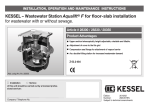
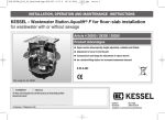
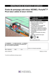
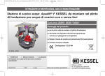
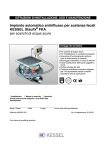
INSTALLATION AND OPERATING MANUAL
KESSEL - Staufix® SWA Backwater Valve for wastewater with or without sewage
KESSEL-Controlfix® Clean-Out
Product Advantages:
For wastewater with or without raw sewage
For installation in exposed or concrete slab piping
Self closing backwater flap during backwater / flooding (depending on model)
Also for use as clean-out for pipe access and inspection
Staufix® SWA for in the floor installation (concrete slab) offers vertically
adjustable, twistable and tiltable upper section for easy installation
Upgradable to KESSEL Staufix® FKA automated backwater valve and
KESSEL Pumpfix F backwater valve with integrated sewage pump
Offers full channel wastewater passage
Simple maintenance and service
LGA
Landesgewerbeamt Bayern
DIN EN 13564 Type 2
Bauart
geprü
gepr
geprüft
üft
und ü
überwacht
berwacht
heit
cher
t
mit Si te Qualitä
geprüf
Installation
Training
Commissioning
This system was installed and commissioned by the following service company:
Name / Signature
Date
Location
Company stamp
Edition
02/2011
Nr.
010-841EN
Subject to technical amendments
Table of Contents
1. General
1.1
1.2
1.3
Application Staufix® SWA.................................................................... Page
Application Controfix® ......................................................................... Page
Contents of delivery .............................................................................. Page
23
23
23
2.1
2.2
2.3
2.4
General instructions..........................................................................
Concrete slab installation..................................................................
Extended depth installation In concrete slab....................................
Exposed pipe installation ..................................................................
Installation in moisture /Groundwater areas .....................................
Page
Page
Page
Page
Page
24
25
26
26
26
3. Commissioning
3.1
Operational check according to DIN EN 13564 ............................... Page
28
4. nspection and Maintenance
4.1
4.2
4.2.1
Inspection ......................................................................................... Page
Maintenance ..................................................................................... Page
Assembly of both covers................................................................... Page
29
29
31
5. Replacement Parts
.......................................................................................................... Page
32
6. Warranty
.......................................................................................................... Page
34
7. Declaration of Conformity (CE)
.......................................................................................................... Page
15
8. Commissioning Protocol
for installer ........................................................................................ Page
37
9. Commissioning Protocol
for installation company .................................................................... Page
39
2. Installation
22
1. General
Dear Customer,
Before installing and commissioning this
KESSEL Staufix® SWA or Controfix® ,
please thoroughly read through this manual and follow all instructions!
Please make sure that nothing was damaged during the shipment of this item. In case
damage did occur during the shipment please go to Section 5 - Guarantee
1.1 Application of the Staufix® SWA
The KESSEL Staufix® SWA backwater valve
is designed to be installed in wastewater drainage pipes with or without raw sewage. The
backwater valve prevents wastewater from
backing up the drainage pipe during backwater / flooding. The SWA should be kept in good
operating condition and should be accessible
at all times. During normal conditions the backwater flap is in the vertical, free handing position. Wastewater draining out of the building
pushes the flap open and is allowed to flow
through the SWA and out of the building. The
SWA is equipped with a manual flap locking
valve which can be used to fully lock the flap
shut – allowing no wastewater in either direction to pass through the valve. In the case that
the drainage pipes connected to the Staufix®
SWA will not be used over extended periods of
time it is recommended that the flap is securely locked with the locking lever. Important is
that when the wastewater pipes return to service that the flap is unlocked. DIN EN 12056
and DIN EN 13564 should be followed which
regulated the drainage of building and use of
backwater valves.
1.2 Application Controfix®
The KESSEL Controfix® serves as the body
housing for all KESSEL Staufix® and Pumpfix
series backwater valves. The following installation instructions should be heeded. Since the
KESSEL Controfix® serves as a cleanout or
access to the drainage piping, the Controfix®
does not contain any backwater flaps and thus
does not offer any protection against backwater. Upgrade packages are available that can
23
be used to upgrade the Controfix® to any
KESSEL Staufix® or Pumpfix backwater valves.
1.3 Contents of Delivery
The Staufix® SWA delivery consists of a body
/ housing with cover including the emergency
closure lever (closure lever not included with a
Controfix® ), and installation and operating
manual (Article Number 010-841) and a seethru test funnel used for testing the valve after
installation (test funnel not included with a
Controfix® ).
2. Installation
no wastewater will be able to flow through the backwater valve meaning
that the building’s own wastewater will flood out of the lowest drainage
fixture connected (normally in the basement) to the backwater valve.
General instructions for installation of backwater valves
According to DIN EN 12056 it is not allowed to connect all drainage fixtures from a building (including those located above the backwater level
– ground level) through a backwater valve. The reason being that when
the backwater flap is in the closed position due to backwater / flooding
Correct installation of a backwater valve
Incorrect installation of a backwater valve
Right:
Wrong
Backwater
level
Backwater
level
Backwater valve
Backwater valve
Sewer
Sewer
DIN EN 12056 specifically states that only drainage fixtures below the
backwater level may be connected to a backwater valve. All drainage
fixtures above the backwater level should be drained through a separate pipe directly into the sewer (not through the backwater valve). This
means that the home / building must be equipped with separate drai-
nage pipes. A building’s wastewater from above the backwater level
(above ground level) can drain freely into the sewer at all times. During backwater the higher head / pressure of wastewater above the
backwater level will force its way into the surcharged sewer and will not
flood the basement / lower levels. Rainwater drainage pipes must not
24
2. Installation
be connected to a backwater valve.
Please note:
DIN EN 12056 requirements should be closely followed during the planning and installing of drainage pipes! Vertical drainage pipes connected to a backwater valve
should not be connect directly in front of
the backwater valve but should be connected at least 1 meter before the backwater
valve – this is the so called ‘wastewater calming’ area. A backwater valves should also
be installed so that access to the valve for
service, maintenance or repair is possible.
CAUTION: Make sure that the backwater valve is installed in the proper direction and is not installed backwards.
KESSEL backwater valves are equipped
with flow direction arrows to make sure
that the valve is installed in the proper
direction.
2.1 Concrete slab installation of a KESSELStaufix® SWA (Nr. 73100.10 S/X, 73125.10
S/X, 73150.10 S/X, 73200.10 S/X). This information is also valid for the installation of the Con-
trolfix® . The Staufix® SWA body should be installed perfectly horizontal (please see illustration 1). The included gasket should be placed into
the recessed area of the housing (as shown in
illustration 2) and then the upper portion of this
gasket should be lubricated. The included upper
section can then be inserted into the housing as
seen in illustration 3. After installation inspect the
gasket to make sure it has been installed properly.
CAUTION:
In the case that a shallow installation is
required in a concrete floor slab it may
be necessary to shorten the upper section which can be done by sawing off
the required lower portion of the upper
section. The maximum depth of groundwater the concrete slab Staufix®
should be installed in is 2 meters.
It is recommended that a conduit pipe
is laid and connected to the Staufix®
SWA body in the case that the system is
upgraded at a later date which would
require that a power cable is connected
to this system.
25
Illustr. 1
Illustr. 2
Illustr. 3
Illustr. 4
Illustr. 5
2. Installation
The second gasket must be inserted in the
cover. Important is that the sealing lip and
centering tip are pointing up. The centering
tip is to be inserted in the appropriate recessed area as seen in illustration 5. During installation the valve should remain clean and
it should be assured that no foreign objects
such as trash or debris are in the valve.
Recessed cover for on-site tiling (maximum
tile height including tile adhesive – 15mm)
The recessed cover (series X) allows the flooring material (tile for example) to also be installed in the recessed cover so that the finished cover matches the flooring surface. If
tiles will be placed into the recessed cover it
is important that the proper adhesive material is used and the following instructions are
followed:
Tiles
a) The inner surface of the recessed cover
should be coated with a bonding material
which sticks to ABS (such as PCI base
coat 303). After this surface coat has properly dried the tile surface can now be laid
into the recessed upper section by using
a silicon adhesive. This method is ideal for
thinner tiles since the remaining height
can be built up with the tile mortar.
b) Installing tiles with PCI-Silcoferm S (self
adhering silicone). This method is ideal
for thicker tiles since a thinner adhesive
surface is used.
Tiling with natural stone such as granite,
marble or agglomarmor
a) The inner surface of the recessed cover
should be coated with a boding material
which sticks to ABS (such as PCI base
coat 303). The natural stone surface can
then be laid into the covers using an appropriate adhesive (for example PCI-Carralit)
b) Installing a natural stone surface a with a
special silicon such as PCI-Carraferm.
Follow the same instructions as in the
‘Tiles’ section above.
2.2 Extended Depth Installation (Nr. 83071)
If the Staufix® SWA is to be installed in an
high groundwater or high earth moisture area
then the instructions in Section 2.4 must be
followed. Depending on the required depth
of installation, either one or two of the KESSEL extension sections can be used.
26
Connection gaskets are supplied with the
83071 and should be properly lubricated as
stated previously. In order to reach the properly installation height when using extension section(s) it may be required to shorted
the top upper section.
Caution! Using 3 or more extension sections
does not allow proper access to the valve for
service or repair and is not recommended.
2.3 Installation in Exposed Pipes (Nr.
73100.10, 73125.10, 73150.10, 73200.10)
The Staufix® for exposed pipe installation
is supplied with a protective cover to prevent
dust and debris of entering the system and
to also help prevent any type of damage to
the system. This protected cover is not
water tight. To remove the protective cover
simple lift both clips on one side of the cover
Before the black lower part of the protective
hood is dismantled, the feed and drain covers must be removed.
2.4 Installation in high groundwater /
earth moisture areas
In the case that the Staufix® SWA for concrete slab installation is to be installed in a
floor slab which will be protected against
Betonboden
Schutzbeton
Abdichtung
Unterbeton
2. Installation
2
groundwater or earth moisture – sealing
gasket set 83023 must be used (accessory). If the concrete slab will be equipped
with a membrane or sheet – this sheet is to
be connected to the Staufix® SWA body
with the counter flange supplied with the
83023. In the case that a water proof concrete is being used then the heavy duty
Kautschuk seal (included with the 83023) is
inserted and then fixed tight with the counter flange. Please install the Kautschuk flange properly so that the pre-drillled holes in
1
the Kautschuk seal match up with the screw holes of the counter flange. (see illustration
6).
In the case that the water tight slab barrier is penetrated by drainage pipes or conduit pipes
to the SWA, it should be assured that these penetration are also water / moisture tight.
Installation diagram (example Pumpfix® F)
Concrete floor with moisture protective
sheet
Tiles
Fliesen
Screed
Estrich
Insulation
Dämmung
Concrete
slab
Betonboden
Protective
concrete
Schutzbeton
Moisture
protective
Abdichtung
Unterbeton
sub
slab
BWS *
Compression seal
flange
Illustr. 6
Concrete floor with waterproof concrete
Tiles
Fliesen
Screed
Estrich
Insulation
Dämmung
Waterproof
Betonboden
concrete floor
BWS *
4
2
3
1
4
Seal seat (83023)
• Counterflange
• Sealing sheet
3
4
➀ KESSEL-Pumpfix® F, Staufix® FKA,
Staufix® SWA, Controlfix
➁ Groundwater protection set (83023)
➂ Extension section (83071)
5
2
1
➃ DN 100 intermediate section with stainless steel counter flange (27198)
➄ Elastomeric sealing barrer (27159)
Fliesen
Installation with extension
section Article Number 83071
Estrich
BWS *
The
height of the groundwater
sealing flange can be adjusted on-site if using the 83071 exDämmung
tension section. No more Betonboden
than 2 extension sections should be used to assure proper access to the backwater valve for service or repair. It may be required that the upper section
is shortened to meet on-site installation heights / requirements.
4
2
5
1
27
3. Commissioning
Function / Sealing test according to DIN EN 13564
➁
Manually lock the outlet side backwater flap with the manual closure lever (number 3 on illustration). Unscrew the
red ½ inch test plug (1) on the cover and connect the supplied see-thru test funnel (2). Add clear water into the funnel until the water level inside the funnel reached the 10cm
mark (this may require significant filling of water since the
Staufix® SWA body must first be completely filled with
water before the filter level is reached). Over a 10 minute
period, observe the water level inside the see-thru funnel.
If the water level decreases, refill to the 10cm mark and record how much water is required to keep the water level
at 10cm. If no more than 500ml of water was required to
keep the water level at the 10cm mark during the 10 minute test then the valve is considered tight.
Screwed
sealing plug
R1/2"
➀
➂
28
4. Inspection and Maintenance
4.1 Inspection
The backwater valve should be checked on
a monthly basis by the owner or a representative of the owner. The manual closure lever
should be shut, locked and re-opened multiple times. Please make sure that after the inspection that manual closure lever is in the
Open position.
4.2 Maintenance (Illustrations 7-9)
The Inspection and Maintenance card included with this product should be kept in the immediate vicinity of the Staufix® SWA (DIN
1986-3)
Attention:
● The Staufix® SWA guarantee will become void if backwater valve is not maintained and serviced according to the
manual and the appropriate norms / regulations!
● Not properly maintaining and servicing
this product could limit insurance
claims based on this product!
Illustr. 8
Illustr. 7
a) Close and lock the manual closure lever
b) Remove cover
Flap holder (d)
29
a) Remove flap and flap
housing
b) Clean all parts
c) Check condition of gaskets / seals
Apply lubricant!
Illustr. 9
a) Lubricate the flap housing
gasket as well as the closure lever.
b) Replace flap housing in
the proper location (guide
sleeves)
c) Insure covers are replaced
properly – 4.2.1 (see page
12)
d) Check to insure flap housing is securely in place
e) Conduct function / sealing
test as described in 3.3
4. Inspection and Maintenance
The backwater needs to be checked every six
months at a minimum by a qualified and licensed service technician. During the inspection no
wastewater should pass through the backwater
valve.
The following should take place during this inspection:
① Any debris or build up should be removed
from the parts of the body (thorough cleaning)
② The condition of gaskets / seals and the
surfaces they come in contact with should
be inspected – if required the gasket / seal
should be replaced (see illustrations 7 to 9)
③ Check for proper movement of the two flaps
as well as the manual closure lever – lubricate if necessary
④ Check to make sure the system is water
tight and in proper operating condition by
performing the function / sealing test (see
Chapter 3)
Manual closure lever
closed open (operation)
Direction of Flow
Illustr. 10
30
4. Inspection and Maintenance
4.2.1 Assembly of both covers
(see Illustrations 11 and 12)
Insert cover housing at an angle as shown and then push other side down. Lock cover in place with the finger clips.
All 4 cover closure clips in the locked position
Illustr. 11
31
Illustr. 12
5. Replacement Parts
Staufix® SWA for exposed pipe installations
Description
➀ SWA cover (inlet side)
➁ SWA cover (outlet side)
➂ Backwater flaps
➃ Housing for backwater flap
➄ Protective cover
➅ Transition section
Test funnel
Gasket set (for cover, inlet and outlet)
Art.-Nr.
80013
80014
80033
80034
83031
83032
70214
70318
➀
햶
햳
햴
➃
32
➅
5. Replacement Parts
Staufix® SWA for concrete slab installations
Description
➀ SWA cover (inlet side)
➁ SWA cover (outlet side)
➂ Backwater flaps
➃ Housing for backwater flap
Gasket set (for cover, inlet and outlet)
Art.-Nr.
80013
80014
80033
80034
70318
➀
햳
햴
➃
33
6. Warranty
1. In the case that a KESSEL product is defective, KESSEL has the option of repairing
or replacing the product. If the product remains defective after the second attempt to
repair or replace the product or it is economically unfeasible to repair or replace the
product, the customer has the right to cancel the order / contract or reduce payment
accordingly. KESSEL must be notified immediately in writing of defects in a product.
In the case that the defect is not visible or
difficult to detect, KESSEL must be notified
immediately in writing of the defect as soon
as it is discovered. If the product is repaired
or replaced, the newly repaired or replaced
product shall receive a new warranty identical to that which the original (defective)
product was granted. The term defective
product refers only to the product or part
needing repair or replacement and not ne-
cessarily to the entire product or unit. KESSEL products are warranted for a period of
24 month. This warranty period begins on
the day the product is shipped form KESSEL to its customer. The warranty only applies to newly manufactured products. Additional information can be found in section
377 of the HGB.
In addition to the standard warranty, KESSEL offers an additional 20 year warranty on
the polymer bodies of class I / II fuel separators, grease separators, inspection chambers, wastewater treatment systems and
rainwater storage tanks. This additional
warranty applies to the watertightness, usability and structural soundness of the product.
A requirement of this additional warranty is
that the product is properly installed and
operated in accordance with the valid in-
34
stallation and user's manual as well as the
corresponding norms / regulations.
2. Wear and tear on a product will not be considered a defect. Problems with products
resulting from improper installation, handling or maintenance will also be considered
a defect.
Note: Only the manufacturer may open sealed components or screw connections.
Otherwise, the warranty may become null
and void
01.06.2010
Notice
36
-----✃---------------------------------------------------------------------------------------------------------------------
8. Commissioning Protocol for installer
Type description *
KESSEL order number *
Date of manufacture *
(* according to type plate/invoice)
Object description / system operator
Planner
Adress / Telephone
Planner
Adress / Telephone
Installation company involved
Adress / Telephone
Person authorised to perform the acceptance
Adress / Telephone
Person responsible for handover
Other remarks
The initial installation and instruction listed was carried out in the presence of the person authorised to perform the acceptance and
the system operator.
______________________________
______________________________
_________________________
Place, date
Signature of authorised person
Signature of system operator
37
Notice
38
Page heraustrennen (zum Verbleib beim einbauenden Unternehmen)
------✃---------------------------------------------------------------------------------------------------------------------
9. Commissioning Protocol for installion company
Handover certificate (copy for the company carrying out the installation)
❏
The initial operation and instruction was carried out in the presence of the person authorised to perform the acceptance and the
system operator.
❏
The system operator/person authorised to perform the acceptance was informed about the obligation to service the product according to the enclosed operating instructions.
❏
Initial operation and instruction were not carried out.
The client/ person responsible for initial operation was handed the following components and/or product components
Initial operation and instruction is being carried out by (company, address, contact, phone)
The exact coordination of the dates for initial operation/instruction is being carried out by the system operator and person responsible for
initial operation.
Place, date
Signature of person
authorised to perform acceptance
Signature of system operator
39
Signature of the company
carrying out the installation work
K Backwater protection
K Lifting Stations and pumps
K Drains and shower channels
K Separators
-Grease Separators
-Oil-/ Fuel-/Coalescence Separators
-Starch Separators
-Sediment Separators
K Septic Systems
K Inspection Chambers
K Rainwater Management Systems