1
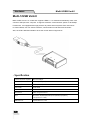
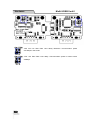
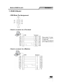
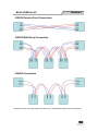
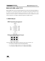
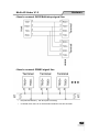
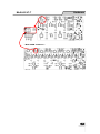
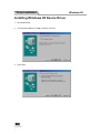
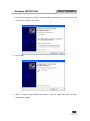
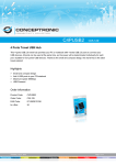
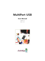
MultiPort USB User Manual Version 2.8 2011. 07. 16 Revision History Revision Date Version Pages Description 2006-07-14 2.0 All Initial Release by shlee 2007-08-02 2.1 Partial Vista x32 added khheo 2008-05-13 2.2 Partial Multi-1 & Win2008 added by hjnoh 2009-05-26 2.3 Partial Auto Install Added by hjnoh 2009-10-26 2.4 Partial Modified by ymwon 2010-2-08 2.5 Partial Modified by ghpark 2010-10-18 2.6 Partial Modified by Loius Kim 2010-11-16 2.7 Partial Modified by hsjung 2011-7-19 2.8 Partial Modified by ymwon Copyright 2006 SystemBase Co., Ltd. All rights reserved. Website: http://www.sysbas.com/ Tel: 82-2-855-0501 Fax: 82-2-855-0580 16th Fl. Daerung Post Tower-1, 212-8, Guro-dong, Guro-gu, Seoul, Korea For any inquiries or comments, contact [email protected] 2 Contents What is USB MultiPort? ................................................................................................................. 5 Multiport USB Specifications ......................................................................................................... 6 Multi-1/USB Ver4.0 ........................................................................................................................ 7 - Specification ........................................................................................................................ 7 1. RS232 Model ..................................................................................................................... 8 2. RS422, RS485 Model ........................................................................................................ 9 Multi-2/USB Ver4.0 ...................................................................................................................... 13 - Specification ...................................................................................................................... 13 1. RS232 Model ................................................................................................................... 14 2. RS422, RS485 Model ...................................................................................................... 15 Multi-4/USB Ver4.0 ...................................................................................................................... 19 - Specification ...................................................................................................................... 19 1. RS232 Model ................................................................................................................... 20 2. RS422, RS485 Model ...................................................................................................... 21 Multi-4/8 USB under V1.5 ............................................................................................................ 25 1. RS232 Model ................................................................................................................... 25 2. RS422, RS485 Model ...................................................................................................... 27 Multi-4/8 USB V1.5, V1.6 ............................................................................................................ 29 1. RS232 Model ................................................................................................................... 29 2. Combo (RS422/RS485) Model ........................................................................................ 30 Multi-4/8 USB V1.7 ...................................................................................................................... 34 1. RS232 Model ................................................................................................................... 34 2. Combo (RS422/RS485) Model ........................................................................................ 35 Installing Windows 98 Device Driver ........................................................................................... 39 Installing Windows 2000/XP/2003 Device Driver ........................................................................ 41 Installing Window Vista/2008 Device Driver ................................................................................ 44 Installing Window 7 Device Driver ............................................................................................... 47 Automatic Driver Installation in Windows .................................................................................... 51 Windows Device Driver Setup ..................................................................................................... 53 Removing Windows Driver .......................................................................................................... 56 1. Remove Device Driver Using Device Manager ............................................................ 57 2. Using FTClean.exe ....................................................................................................... 62 3. Using CDMUnistaller.exe .............................................................................................. 66 3 Multi-4/8 USB History .................................................................................................................. 68 4 What is USB MultiPort? USB is a complex word of “Universal”, meaning all peripheral devices use the same connector, and “Serial”, meaning devices are connected as a daisy chain through serial transmission. USB is an interface suggesting a solution to inconvenience and inefficiency caused by slow speed and limited device connection of existing external ports(serial or parallel). Compared to external ports that were only used to connect devices such as modems, printers and scanners, USB is powerful in that it connects all types of basic peripheral devices that were each connected via different types. Also, when a new device is plugged, it‟s auto-detected without any rebooting or setup process, enabling 127 connections maximum. Installation is handy since PnP is perfectly supported. No extra equipment is needed since most of the main-board chipsets include the USB controller. USB cable type supported is type A, which can utilize the USB port of the PC or the USB hub. This product obtains power from USB, and this makes the product powerful since no external power supply is required. 5 Multi-4/8 Hardware Multiport USB Specifications - Hardware Number of Ports: 1, 2, 4, 8 USB Interface: USB Spec 1.1/2.0 Serial Interface: RS232/COMBO(422/485) LED: Tx and Rx per each port Serial Connector: DB9 (Male) 1,2,4/ DB9 (Female) Serial Communication Speed: 921.6Kbps maximum External Power: Selectable/Disable(*1) 4,8 Panel type - Software Supports Windows 98/2000/XP/2003/Vista/2008/7, and Linux Driver, OS X Driver (*2) Supports Windows XP/2003/Vista/2008/7 x64 *1: You can connect external power supply to Panel type USB MultiPort H/W ver. 1.5 or above only. *2: If you would like to use USB Multiport for Linux, please contact [email protected] 6 Hardware Multi-2/USB Ver4.0 Multi-1/USB Ver4.0 Multi-1/USB Ver4.0 is a model that supports USB2.0. It is detected automatically when user connects USB port with computer. It supports maximum communication speed of 921.6Kbps. Furthermore, it is equipped with surge protector to protect internal systems from outer shock. In Combo Model, user can set line interface, communication mode and terminal resistor. Also, the LED is attached outside to show the current status of signal lines. - Specification Communication Speed Max 921.6Kbps Bus Interface USB 2.0(Full Speed) Line Interface RS232/RS422/RS485 Controller FTDI 232R Connector DB9 Male Protection 15kV Surge Protector O/S Windows 98/2000/XP/2003/Vista/2008/7(32/64bit), Linux(2.6.31 or later) Manufaturer 7 SystemBase Co., Ltd Multi-1/USB Ver4.0 Hardware 1. RS232 Model - DB9 Male Pin Assignment - How to connect to a Terminal - How to connect to a Modem 8 Hardware Multi-1/USB Ver4.0 2. RS422, RS485 Model - DB9 Male Pin Assignment - DIP Switch Setting NO Function ON OFF 1 Interface Select RS485 RS422 2 Echo/Non-Echo Select Echo Non-Echo 3 RS422 terminal resistor Install Uninstall 4 RS485 terminal resistor Install Uninstall 9 Multi-1/USB Ver4.0 Hardware - Jumper Setting ① Loosen the two screw on the bottom case. ② Remove the side cap. Look at the rear side of case, you can find the small grooved. ③ Top cover is slid to the inside of the case. 10 Hardware Multi-1/USB Ver4.0 10M: Not use Slew Rate Limit ability. Maximum communication speed 921.6Kbps in this mode. 250K: Use Slew Rate Limit ability. Communication speed is limited under 250Kbps. 11 Multi-1/USB Ver4.0 Hardware - RS422 Point-to-Point Connection - RS422 Multi-Drop Connection - RS485 Connection RS485, like LAN, uses Half Duplex Bus and has no classification between host and terminal. 12 Hardware Multi-2/USB Ver4.0 Multi-2/USB Ver4.0 Multi-2/USB Ver4.0 is a model that supports USB2.0. It is detected automatically when user connects USB port with computer. It supports maximum communication speed of 921.6Kbps. Furthermore, it is equipped with surge protector to protect internal systems from outer shock. In Combo Model, user can set line interface, communication mode and terminal resistor. Also, the LED is attached outside to show the current status of signal lines. - Specification Communication Speed Max 921.6Kbps Bus Interface USB 2.0 Line Interface RS232/RS422/RS485 Controller FTDI 2232H Connector DB9 Male Protection 15kV Surge Protector O/S Windows XP/2003/Vista/2008/7(32/64 bit) Linux (2.6.31 or later) Manufaturer 13 SystemBase Co., Ltd Multi-2/USB Ver4.0 Hardware 1. RS232 Model - DB9 Male Pin Assignment - How to connect to a Terminal - How to connect to a Modem 14 Hardware Multi-2/USB Ver4.0 2. RS422, RS485 Model - DB9 Male Pin Assignment - DIP Switch Setting NO Function ON OFF 1 Interface Select RS485 RS422 2 Echo/Non-Echo Select Echo Non-Echo 3 RS422 terminal resistor Install Uninstall 4 RS485 terminal resistor Install Uninstall 15 Multi-2/USB Ver4.0 Hardware - Jumper Setting ① Loosen the two screw on the bottom case. ② Remove the side cap. Look at the rear side of case, you can find the small grooved. ③ Top cover is slid to the inside of the case. ④ Two Top Cover cases in the same way is open. 16 Hardware Multi-2/USB Ver4.0 10M: Not use Slew Rate Limit ability. Maximum communication speed 921.6Kbps in this mode. 250K: Use Slew Rate Limit ability. Communication speed is limited under 250Kbps. 17 Multi-2/USB Ver4.0 Hardware - RS422 Point-to-Point Connection - RS422 Multi-Drop Connection - RS485 Connection RS485, like LAN, uses Half Duplex Bus and has no classification between host and terminal. 18 Hardware Multi-2/USB Ver4.0 Multi-4/USB Ver4.0 Multi-4/USB Ver4.0 is a model that supports USB2.0. It is detected automatically when user connects USB port with computer. It supports maximum communication speed of 921.6Kbps. Furthermore, it is equipped with surge protector to protect internal systems from outer shock. In Combo Model, user can set line interface, communication mode and terminal resistor. Also, the LED is attached outside to show the current status of signal lines. - Specification Communication Speed Max 921.6Kbps Bus Interface USB 2.0 Line Interface RS232/RS422/RS485 Controller FTDI 4232H Connector DB9 Male Protection 15kV Surge Protector O/S Windows XP/2003/Vista/2008/7 (32/64 bit) Linux (2.6.31 or later) Manufaturer 19 SystemBase Co., Ltd Multi-4/USB Ver4.0 Hardware 1. RS232 Model - DB9 Male Pin Assignment - How to connect to a Terminal - How to connect to a Modem 20 Hardware Multi-4/USB Ver4.0 2. RS422, RS485 Model - DB9 Male Pin Assignment - DIP Switch Setting NO Function ON OFF 1 Interface Select RS485 RS422 2 Echo/Non-Echo Select Echo Non-Echo 3 RS422 terminal resistor Install Uninstall 4 RS485 terminal resistor Install Uninstall 21 Multi-4/USB Ver4.0 Hardware - Jumper Setting ① Loosen the two screw on the bottom case. ② Remove the side cap. Look at the rear side of case, you can find the small grooved. ③ Top cover is slid to the inside of the case. ④ Top Cover cases in the same way is open. 22 Hardware Multi-4/USB Ver4.0 10M: Not use Slew Rate Limit ability. Maximum communication speed 921.6Kbps in this mode. 250K: Use Slew Rate Limit ability. Communication speed is limited under 250Kbps. 23 Multi-4/USB Ver4.0 Hardware - RS422 Point-to-Point Connection - RS422 Multi-Drop Connection - RS485 Connection RS485, like LAN, uses Half Duplex Bus and has no classification between host and terminal. 24 Hardware Multi-4/8 Under V1.5 Multi-4/8 USB under V1.5 Multi-4/8 USB under V1.5 can work with USB power only, so does not need external adapter. It can supply +5V or +12V when the device needs. This feature is useful when small devices such as cash box, bar-code reader and printer are connected to PC POS system. +5V or +12V adapter don‟t affect the operation of USB MultiPort because this part is separated from serial communication part. This voltage is supplied through 9th pin of DB9 connector. 1. RS232 Model - DB9 Female Pin Assignment - External Voltage Supply Jumper There are jumpers for each port when opening the case. Users can select 1 of 3. RI: Use 9th pin of DB9 connector as RI signal (Default) 5V: Use 9th pin of DB9 connector as +5V supply (needs adapter) 12V: Use 9th pin of DB9 connector as +12 supply (needs adapter) 25 Multi-4/8 Under V1.5 Hardware - How to connect to a Terminal - How to connect to a Modem 26 Hardware Multi-4/8 Under V1.5 2. RS422, RS485 Model - DB9 Female Pin - How to connect RS422 Point-to-point signal line 27 Multi-4/8 Under V1.5 Hardware - How to connect S422 Multi-drop signal line - How to connect RS485 signal line RT(Terminal Resistor) : 120 Ohm (Not necessary) In RS485 mode, there is no discrimination between Host and Terminal. 28 Hardware Multi 4/8 V1.5 & 1.6 Multi-4/8 USB V1.5, V1.6 Multi-4/8 USB V1.5 & V1.6 can work with USB power, so does not need external adapter. But it can work with external adapter when it needs more stable power supply. It can supply +5V when the device needs. This feature is useful when small devices such as cash box, bar-code reader and printer are connected to PC POS system. +5V can be supplied even when Multi-4/8 USB don‟t use external adapter. This supply voltage is supplied through 9th pin of DB9 connector. (Caution: Never use adapter except +5V. It may damage the MultiPort. ) 1. RS232 Model - DB9 Female Pin Assignment - External Voltage Supply Jumper Multi-4U RS232 V1.5, V1.6 29 Multi 4/8 V1.5 & 1.6 Hardware Multi-8U RS232 V1.5, V1.6 There are jumpers for each port when opening the case. Users can select 1 of 2. RI: Use 9th pin of DB9 connector as RI signal (Default) Power: Use 9th pin of DB9 connector as +5V supply 2. Combo (RS422/RS485) Model - DB9 Female Pin Assignment 30 Hardware Multi 4/8 V1.5 & 1.6 - Switch for selecting RS422/RS485 line interface Multi-4/USB Combo V1.5, V1.6 Multi-8/USB Combo V1.5, V1.6 31 1 2 Interface Mode OFF OFF RS422 Point-to-Point OFF ON RS422 Multi-Drop ON OFF RS485 Non-Echo ON ON RS485 Echo Multi 4/8 V1.5 & 1.6 Hardware - Portx RT: RS422, RS485 Terminal Resistor Multi-4/USB Combo V1.5, V1.6 Multi-8/USB Combo V1.5, V1.6 422: RS422 Terminal Resistor 485: RS485 Terminal Resistor NONE: No Terminal Resistor - External Voltage Supply - In Multi-4/8 USB Combo model, +5V is always supplied through the 9th pin of DB9 connector. Users can connect 9th pin to the device if they are to supply +5V to the device. 32 Hardware Multi 4/8 V1.5 & 1.6 - Jumper for Slew Rate setting Slew Rate Limit allows communication without errors by activating slew-rate driver to reduce reflection waves and EMI electromagnetic waves. However, communication speed is limited when it is used. Multi-4/USB Combo V1.5, 1.6 Multi-8/USB Combo V1.5, V1.6 Slew Rate Limit Off 33 Slew Rate Limit On Multi 4/8 V1.7 Hardware Multi-4/8 USB V1.7 Since Multi-USB V1.7 is used USB 2.0 Controller, the performance is higher than ever. Throughput is increased about 30% than ever, you’ll use more smoothly. Also, It can supply +5V when the device needs. This feature is useful when small devices such as cash box, bar-code reader and printer are connected to PC POS system. +5V can be supplied even when Multi-4/8 USB don‟t use external adapter. This supply voltage is supplied through 9th pin of DB9 connector. 1. RS232 Model - DB9 Female Pin Assignment - External Voltage Supply Jumper Multi-4U RS232 V1.7 34 Hardware Multi 4/8 V1.7 Multi-4U RS232 V1.7 There are jumpers for each port when opening the case. Users can select 1 of 2. RI: Use 9th pin of DB9 connector as RI signal (Default) Power: Use 9th pin of DB9 connector as +5V supply <RI> <Power> 2. Combo (RS422/RS485) Model - DB9 Female Pin Assignment 35 Multi 4/8 V1.7 Hardware - Switch for selecting RS422/RS485 line interface This is switch for selecting RS422/RS485 line interface. Default is RS485. - Multi-4/USB Combo V1.7 Power supply whether or not through 9th pin Power supply whether or not through 9th pin - Multi-8 USB/USB Combo V1.7 1 2 Interface Mode OFF OFF RS422 Point-to-Point OFF ON RS422 Multi-Drop ON OFF RS485 Non-Echo ON ON RS485 Echo 36 Hardware Multi 4/8 V1.7 - Portx RT: RS422, RS485 Terminal Resistor - Multi-4/USB Combo V1.7 - Multi-8/USB Combo V1.7 - Jumper for Slew Rate setting Slew Rate Limit allows communication without errors by activating slew-rate driver to reduce reflection waves and EMI electromagnetic waves. However, communication speed is limited when it is used. - Multi-4/USB Combo V1.7 37 Multi 4/8 V1.7 Hardware - Multi-8/USB Combo V1.7 38 Driver Installation Installing Windows 98 Device Driver 1. Run Windows 98. 2. Connect Multi-USB to the USB connector of the PC. 3. Click “Next”. 39 Windows 98 Windows 98 Driver Installation 4. Click “Next” 5. Check “Specify a location” and specify correct location of Windows 98 device driver. If you have the driver CD provided with MultiPort product, put it into the CD-ROM drive and specify the location of the driver as “[CD Rom]:\Driver\USB\Win98”. Then click “Next”. 6. Click “Finish” to complete the installation process. 7. Repeat steps 3-6 when “Add New Hardware Wizard” restarts. 40 Driver Installation Windows 2000/XP/2003 Installing Windows 2000/XP/2003 Device Driver Install procedures for 64bit drivers are identical to 32bit drivers 1. Run Windows 2000/XP/2003. 2. Connect USB MultiPort to your PC‟s USB port. 3. Insert media CD (provided with MultiPort) into the CD drive. 4. Select “Install software automatically (Recommended)”, then click “Next”. 5. Click “Finish”. 6. Steps 4 through 6 automatically install drivers in the CD. “USB Serial Converter” will all be automatically installed. 41 Windows 2000/XP/2003 Driver Installation 7. Following procedures will guide you through installing “USB Serial Port”. Select “No. Do not connect now”, and then click “Next” 8. Click “Finish” 9. Steps 7 through 8 automatically install drivers in the CD. “USB Serial Port” will all be automatically installed. 42 Driver Installation Windows 2000/XP/2003 10. Following picture depicts “Device Manager” after carrying out all steps. As can be seen “USB Serial Converters” and “USB Serial Ports” are successfully installed. The number of lines may vary depending on the product you are using. 11. USB Multiport installation on Window 2000/XP/2003 is now finished. 43 Windows Vista/2008 Driver Installation Installing Window Vista/2008 Device Driver 1. Run Windows Vista/2008 2. Connect USB MultiPort to your PC‟s USB port. 3. Insert media CD(provided with MultiPort) into the CD drive 4. Click “Locate and install driver software (recommended)” on the “Found New Hardware” window. 5. Step 4 will automatically install drivers in the CD. USB <-> Serial Cable will automatically be installed. 6. Following picture depicts Device Manager after carrying out step 4. As can be seen, all “USB Serial Converters” are successfully installed. The number of lines may vary depending on the product you are using. 44 Driver Installation Windows Vista/2008 7. Following procedures will guide you through installing “USB Serial Port”. Select „Don‟t search online‟ 8. Click “Locate & Install driver software (recommended)” on the “New hardware found” window 45 Windows Vista/2008 Driver Installation 9. Following picture depicts “Device Manager” after carrying out step 8. As can be seen, all “USB Serial Converters” and “USB Serial Ports” are successfully installed. 10. “USB Multiport” installation on Window Vista/2008 is now finished 46 Driver Installation Installing Window 7 Device Driver Install procedures for 64bit drivers are identical to 32bit drivers 1. Run Windows 7 2. Connect USB MultiPort to your PC‟s USB port. 3. Insert media CD(provided with MultiPort) into the CD drive 4. Click “Hardware and Sound” in “Control Panel” 5. Following picture depicts Device Manager after carrying out step 4. Click “Device Manager”. 47 Windows 7 Windows 7 6. Driver Installation Right click “USB <-> Serial Cable” in “Device Manager”. then Choose “Update Driver Software” 7. Click “Browse my computer for driver software” in order to install driver manually. 48 Driver Installation 8. Windows 7 Click “Browse” and set driver software‟s location to “[CD]:\Driver\USB\Win2000,XP,2003,Vista,2008,7” 9. Confirm that “USB Serial Converter” is installed normally. Then, right click "USB Serial Port" and follow the same process from number 6 again. 49 Windows 7 Driver Installation 10. Following picture depicts “Device Manager” after carrying out all steps. As can be seen, all “USB Serial Converters” and “USB Serial Ports” are successfully installed. 11. “USB Multiport” installation on Window 7 is now finished 50 Driver Installation Windows Automatic Driver Installation in Windows This procedure applies to Windows 2000, XP, 2003, Vista, 2008, 7 and Windows XP, 2003, Vista, 2008, 7 x64. If you want to install device drivers manually, please refer to manual installation pages. 1. Run Windows. 2. Connect USB MultiPort to your PC‟s USB port. 3. Insert install CD into the CD-ROM drive. 4. If a “Found New Hardware” window appears, click “Cancel”. 5. Go to “[CD]\Driver\USB\Win2000,XP,2003,Vista,2008,7”. Execute “CDM 20600”. 51 Windows Driver Installation 6. When the following Windows appears, click “Run”. 7. Device drivers will be installed automatically. 8. After the installation is completed, the program will terminate. Go to “Control Panel” “Device Manager” or right click “Computer” “Device Manager” to open Device Manager. You will be able to see that “USB Serial Converter” and “USB Serial Port” is successfully installed. 52 Driver Setup Windows Windows Device Driver Setup 1. An advanced properties page is available for devices using the device. To access the advanced properties page, open "Device Manager” in Control Panel. Find the USB serial port you want to change the properties of and right-click on it. Select "Properties" from the menu then select the "Port Settings" tab to get the window below. 53 Windows Driver Setup 2. This page allows configuration of the basic device parameters (i.e. Baud rate, data bits, parity, stop bits and flow control). To access more advanced settings, click on the "Advanced…" button to display the advanced properties page (shown below). 3. This page will allow the following parameters to be altered: COM port number USB buffer sizes Latency timer Alter this to correct compatibility problems for obsolete applications. Read and write timeout values You can alter this for timing of timeout event if there are no more Tx/Rx data. Miscellaneous options Serial Emulator: The function of the serial enumerator is to detect a Plug-and-Play enabled device (such as a serial mouse or serial modem) that is attached to the USB serial port. Serial Printer: If enabled, serial printer will disable timeouts to allow for long delays associated with paper loading. Cancel If Power Off: The Cancel If Power Off option can be used to assist with problems encountered when going into a hibernate or suspend condition. This will cancel any requests received by the driver when going into hibernate or suspend. Event on Surprise Removal 54 Driver Setup Windows : The Event On Surprise Removal option is generally left unselected. If an application sets SERIAL_EV_EVENT2 (refer Windows DDK) in it is event bitmask and this feature is enabled, the device driver will signal this event on surprise removal. Set RTS on Close: Selecting the Set RTS on Close option will set the RTS signal on closing the port. Disable Modem Control at Startup: This option is used to control the modem control signals DTR and RTS at startup. In normal operation, the modem control signals at startup follow the behavior of the legacy port. However, due to timing differences between a legacy COM port and a virtual COM port, a "spike" on one of these signals in the legacy port can appear as an assertion of the signal in the virtual COM port. Devices that monitor these signals can enter the wrong state after an unplug-replug cycle on USB. Note that if \ the "Serial Enumerator" option in the property page is selected, then the enumeration sequence causes the modem control signals to change at startup. So if it is necessary to select "Disable Modem Ctrl At Startup", then it is likely that "Serial Enumerator" should be unchecked in the property page. Don’t adjust these parameters if you can use the device normally. If not, please contact us ([email protected]) about these parameters first. 55 Driver Removal Removing Windows Driver You can be used to remove device driver in three way 1) Using Device Manager. 2) Using FTClean.exe 3) Using CDMunistaller.exe ※ Tip Windows 98, 2000, XP, 2003 using Customers, please remove the driver by FTClean.exe. Windows Vista, 2008 Customers who use the driver in Device Manager, remove it. Customers using Windows 7, please use the CDMunistallerGUI.exe. Multi-USB PID information Multi-1/USB: 6001 Multi-2/USB v1.x: 6001 Multi-2/USB v4.0: 6010 Multi-4/USB v1.x (v1.7 excluded): 6010 Multi-4/USB v1.7/v4.0: 6011 Multi-8/USB v1.x: 6010 USB Multiport will be removed after all removal processes are completed. 56 Driver Removal 1. Remove Device Driver Using Device Manager 1. Execute “Device Manager”. Do not remove USB MultiPort form USB port. USB Multiport will be removed after all removal processes are completed. 2. “USB Serial Converter A/B/C/D” controllers and “USB Serial Port” serial ports can be found. The number of lines may vary depending on the product you are using. Serial ports will be removed first. 57 Driver Removal 3. Find „USB Serial Port (COM#)‟ under “Device Manager->Ports->USB Serial Port (COM#)” and right click on any “USB Serial Port”. Click “Uninstall”. 4. Check the following check box, and click “OK”. 5. Remove rest of the USB Serial Ports. 58 Driver Removal 6. Unlike the first Device Removal Window, check box can not be found. Click “OK” to remove current port. Repeat step 5~6 until all Serial ports are removed. 7. “USB Serial Port” removal is now completed. We will now continue with “USB Serial Converter” removal. 8. Right click on one of the “USB Serial Converter” and click “Uninstall”. 59 Driver Removal 9. Check the “check box” and click “OK”. 10. Remove rest of “USB Serial Converters”. 60 Driver Removal 11. Repeat steps 10~11 until all USB Serial Converters are removed. 61 Driver Removal 2. Using FTClean.exe 1. Remove USB MultiPort from USB connection port. USB MultiPort drivers are now completely removed from your system. 2. Execute “Task Manager”. “USB Serial Converter A/B/C/D” controllers and “USB Serial Port” Serial Ports can be seen. The number of ports may vary depending on the product you are using. These devices must all be removed. 3. Insert install CD in the CD-ROM. Open the folder named “[CD]:\Driver\USB\Win2000,XP,2003,Vista,2008,7”. 62 Driver Removal 4. Execute “FTClean.exe”. Type the correct PID under “PID (Hex)” box, and then click “Clean System”. “PID” refers to the Product ID Multi-1 PID: 6001 Multi-2 Ver4.0 and Old Multi-4/8 PID: 6010 Multi-4 Ver4.0 PID: 6011 5. Click “OK”. 63 Driver Removal 6. Click “Yes”. 7. Click “No”. 8. “FTDI Uninstaller v3.0” window will appear & disappear several times. This is a normal uninstall process so wait until this window does not appear. 64 Driver Removal 9. Driver removal is completed when the following window (FTDI Clean Utility) remains activated without any action. 10. Remove USB MultiPort from USB connection port. 11. The driver removal process is now completed. 65 Driver Removal 3. Using CDMUnistaller.exe 1. Run CDMunistallerGUI.exe in Driver CD. 2. Insert PID number in Product ID Product Name Product ID Multi-1/USB 6001 Multi-2/USB 6010 Multi-4/USB V4.0 and V1.7 6011 Multi-4/USB V1.6 earlier 6010 Multi-8/USB 6010 3. Click the Add button. 66 Driver Removal 4. Click the “Remove Devices”. 5. You can see the screen shown below, if driver is removed. 67 Appendix Appendix Multi-4/8 USB History Version V 1.0 & V 1.1 Feature Using for applying 12V from DC Providing among 12V, 5V, RI through 9(ninth) pin of DB9 Using linear regulator in V1.0. Using switching regulator in V1.1. V 1.2 DC has nothing to do with bus power supply of USB port. DC is used only external power supply. Power supply applied DC is 9(ninth) pin of DB9. Applying 5V to outside using 5V adapter from DC Applying 12V to outside using 12V adapter form DC Output power supply(voltage applied DC) or RI signal through the 9(ninth) pin of DB9 V 1.5 Providing +5V power supply or RI signal through DB9 connector 9 pin(RI) DC can be used additional BUS power supply and external power supply. DC must be used 5V adapter. Using GL850 V 1.6 Providing +5V power supply through DB9 connector 9 pin(RI) DC can be used additional BUS power supply and external power supply. DC must be used 5V adapter. Using GL850A (Discontinued GL850) V1.7 Choosing the high performance USB 2.0 controller, the performance increases 30% than ever. Providing +5V power supply or RI signal through DB9 connector 9 pin(RI) DC can be used additional BUS power supply and external power supply. 68