1
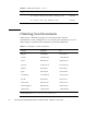
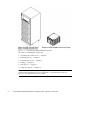
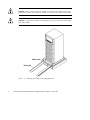
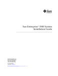
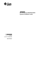
Sun Enterprise 6500/5500/4500
Systems Installation Guide
A Sun Microsystems, Inc.
Business
901 San Antonio Road
Palo Alto, , CA 94303-4900
Part No: 805-2631-10
Revision A, April 1998
USA 650 960-1300 fax 650 969-9131
Sun Enterprise 6500/5500/4500
Systems Installation Guide
Part No: 805-2631-10
Revision A, April 1998
Copyright 1998 Sun Microsystems, Inc. 901 San Antonio Road, Palo Alto, California 94303-4900 U.S.A. All rights reserved.
All rights reserved. This product or document is protected by copyright and distributed under licenses restricting its use, copying,
distribution, and decompilation. No part of this product or document may be reproduced in any form by any means without prior written
authorization of Sun and its licensors, if any.
Portions of this product may be derived from the UNIX® system, licensed from Novell, Inc., and from the Berkeley 4.3 BSD system,
licensed from the University of California. UNIX is a registered trademark in the United States and in other countries and is exclusively
licensed by X/Open Company Ltd. Third-party software, including font technology in this product, is protected by copyright and licensed
from Sun’s suppliers. RESTRICTED RIGHTS: Use, duplication, or disclosure by the U.S. Government is subject to restrictions of FAR
52.227-14(g)(2)(6/87) and FAR 52.227-19(6/87), or DFAR 252.227-7015(b)(6/95) and DFAR 227.7202-3(a).
Sun, Sun Microsystems, the Sun logo, and Solaris are trademarks or registered trademarks of Sun Microsystems, Inc. in the United States
and in other countries. All SPARC trademarks are used under license and are trademarks or registered trademarks of SPARC International,
Inc. in the United States and in other countries. Products bearing SPARC trademarks are based upon an architecture developed by Sun
Microsystems, Inc.
TM
The OPEN LOOK® and Sun Graphical User Interfaces were developed by Sun Microsystems, Inc. for its users and licensees. Sun
acknowledges the pioneering efforts of Xerox Corporation in researching and developing the concept of visual or graphical user interfaces
for the computer industry. Sun holds a nonexclusive license from Xerox to the Xerox Graphical User Interface, which license also covers
Sun’s licensees who implement OPEN LOOK GUIs and otherwise comply with Sun’s written license agreements.
THIS PUBLICATION IS PROVIDED “AS IS” WITHOUT WARRANTY OF ANY KIND, EITHER EXPRESS OR IMPLIED, INCLUDING,
BUT NOT LIMITED TO, THE IMPLIED WARRANTIES OF MERCHANTABILITY, FITNESS FOR A PARTICULAR PURPOSE, OR
NON-INFRINGEMENT.
Copyright 1998 Sun Microsystems, Inc., 901 San Antonio Road, Palo Alto, Californie 94303-4900 U.S.A. Tous droits réservés.
Ce produit ou document est protégé par un copyright et distribué avec des licences qui en restreignent l’utilisation, la copie et la
décompilation. Aucune partie de ce produit ou de sa documentation associée ne peut être reproduite sous aucune forme, par quelque
moyen que ce soit, sans l’autorisation préalable et écrite de Sun et de ses bailleurs de licence, s’il y en a.
Des parties de ce produit pourront être derivées du système UNIX® licencié par Novell, Inc. et du système Berkeley 4.3 BSD licencié par
l’Université de Californie. UNIX est une marque enregistrée aux Etats-Unis et dans d’autres pays, et licenciée exclusivement par X/Open
Company Ltd. Le logiciel détenu par des tiers, et qui comprend la technologie relative aux polices de caractères, est protégé par un
copyright et licencié par des fournisseurs de Sun.
Sun, Sun Microsystems, le logo Sun, et Solaris sont des marques déposées ou enregistrées de Sun Microsystems, Inc. aux Etats-Unis et
dans d’autres pays. Toutes les marques SPARC, utilisées sous licence, sont des marques déposées ou enregistrées de SPARC International,
Inc. aux Etats-Unis et dans d’autres pays. Les produits portant les marques SPARC sont basés sur une architecture développée par Sun
Microsystems, Inc.
TM
Les utilisateurs d’interfaces graphiques OPEN LOOK® et Sun ont été développés de Sun Microsystems, Inc. pour ses utilisateurs et
licenciés. Sun reconnaît les efforts de pionniers de Xerox Corporation pour la recherche et le développement du concept des interfaces
d’utilisation visuelle ou graphique pour l’industrie de l’informatique. Sun détient une licence non exclusive de Xerox sur l’interface
d’utilisation graphique, cette licence couvrant aussi les licenciés de Sun qui mettent en place les utilisateurs d’interfaces graphiques OPEN
LOOK et qui en outre se conforment aux licences écrites de Sun.
CETTE PUBLICATION EST FOURNIE "EN L’ETAT" SANS GARANTIE D’AUCUNE SORTE, NI EXPRESSE NI IMPLICITE, Y COMPRIS,
ET SANS QUE CETTE LISTE NE SOIT LIMITATIVE, DES GARANTIES CONCERNANT LA VALEUR MARCHANDE, L’APTITUDE DES
PRODUITS A REPONDRE A UNE UTILISATION PARTICULIERE OU LE FAIT QU’ILS NE SOIENT PAS CONTREFAISANTS DE
PRODUITS DE TIERS.
Please
Recycle
Contents
Preface
1.
viii
Preparing for Installation
1
Unpacking the Enterprise 6500/5500 Cabinet Systems 3
Shipping and Storing the System 5
Preparing the Electrical Circuits
5
Enterprise 6500/5500 Cabinet Systems 5
Enterprise 4500 System 6
Preparing the Air Conditioning 6
Preparing the Ethernet Network
Preparing the Area
6
8
Enterprise 6500/5500 Cabinet Systems 8
Enterprise 4500 System 9
Preparing the Enterprise 6500/5500 Cabinet Systems 10
Moving the Server
11
Adjusting the Levelling Pads
11
Adding Storage Devices 14
Preparing the Enterprise 4500 System 14
Labelling the System 14
2.
Cabling the System
17
Contents iv
Preparing the System for Cabling
17
Removing and Replacing the Enterprise 6500/5500 Cabinet Rear Door and Kick
Panel 17
Removing the Rear Door and Kick Panel
17
Replacing the Rear Door and Kick Panel
19
Connecting the Power Cords 20
Enterprise 6500/5500 System Power Cord
20
Enterprise 4500 System Power Cord 20
Connecting the Network Cable to the System 21
Connecting the System to the Network
Connecting an ASCII Terminal
23
26
Connecting the Fiber Cable to the I/O+ Board
3.
Connecting External SCSI Devices
29
Powering the System On and Off
33
27
Using JumpStart Automatic Installation 33
Enterprise 6500/5500 Cabinet Systems
34
Powering On the System 34
Reading Boot Messages
39
Interpreting Status LED Patterns
Powering Off the System
40
41
Enterprise 4500 System 42
Powering On the System 42
Reading Boot Messages
45
Interpreting Status LED Patterns
Powering Off the System
46
47
Failure of Network Communications 48
Description of the Problem 48
Determining the Device Names of the I/O+ Boards 49
v
Sun Enterprise 6500/5500/4500 Systems Installation Guide ♦ Revision A, April 1998
Solution 1 49
Solution 2 49
4.
Software 51
Operating System Software and Patches
51
Solaris 2.6 - Patch 105375-04 51
Solstice SyMON Software
51
Dynamic Reconfiguration 52
CPU Over Temperature Safeguard (COS)
A.
52
Regulatory Agency Compliance Statements
53
FCC and DOC Class Notices 53
FCC Class A Notice
53
DOC Class A Notice – Avis DOC, Classe A 54
VCCI Statement
55
Declarations of Conformity 56
Index 59
Contents vi
vii
Sun Enterprise 6500/5500/4500 Systems Installation Guide ♦ Revision A, April 1998
Preface
The Sun Enterprise 6500/5500/4500 Systems Installation Guide provides installation
instructions for factory-configured 16-slot and 8-slot cabinet and standalone server
systems. These instructions are for an experienced system administrator with
networking knowledge.
UNIX Commands
This document may not contain information on basic UNIX®® commands and
procedures such as shutting down the system, booting the system, and configuring
devices.
See one or more of the following for this information:
TM
4 Solaris 2.x Handbook for SMCC Peripherals which contains Solaris
commands
4 AnswerBook
TM
2.x software
online documentation for the Solaris 2.x software environment
4 Other software documentation that you received with your system
Typographic Conventions
Preface
viii
TABLE P–1
Typographic Conventions
Typeface or
Symbol
AaBbCc123
Meaning
Examples
The names of commands, files, and
directories; on-screen computer
output.
Edit your .login file.
Use ls -a to list all files.
% You have mail.
AaBbCc123
What you type, when contrasted
with on-screen computer output.
% su
Password:
Book titles, new words or terms,
words to be emphasized.
AaBbCc123
Command-line variable; replace
with a real name or value.
Read Chapter 6 in the User’s Guide.
These are called class options.
You must be root to do this.
To delete a file, type rm filename.
Shell Prompts
TABLE P–2
ix
Shell Prompts
Shell
Prompt
C shell
machine_name%
C shell superuser
machine_name#
Bourne shell and Korn shell
$
Bourne shell and Korn shell superuser
#
Sun Enterprise 6500/5500/4500 Systems Installation Guide ♦ Revision A, April 1998
Related Documentation
The following documents contain topics that relate to the information in the Sun
Enterprise 6500/5500/4500 Systems Installation Guide.
TABLE P–3
Related Documents
Application
Service
Software
Options
Title
Part Number
Sun Enterprise 6500/5500/4500 Systems Reference Manual
805-2632
SMCC SPARC Hardware Platform Guide
802-5341
Solstice SyMON User’s Guide
802-5355
Dynamic Reconfiguration User’s Guide for Sun Enterprise
6x00/5x00/4x00/3x00 Systems
805-3530
Sun Enterprise Expansion Cabinet Installation and Service
Manual
805-4009
Sun Enterprise 6/5/4/3x00 Board Installation Guide
805-4007
4 Mbyte UltraSPARC II Installation Guide
805-1150
Sun Enterprise 6/5/4/3x00 Systems SIMM Installation Guide
802-5032
SBus+ and Graphics+ I/O Boards (100 MB/sec Fibre
Channels) for Sun Enterprise 6/5/4/3x00 Systems
805-2704
PCI+ I/O Board Installation and Component Replacement for
Sun Enterprise 6/5/4/3x00 Systems
805-1372
Sun Enterprise Systems Peripheral Power Supply Installation
Guide
802-5033
Sun Enterprise Systems Power/Cooling Module Installation
Guide
802-6244
Rackmount Placement Matrix
802-6945
x
TABLE P–3
Related Documents
Application
(continued)
Title
Part Number
Sun Enterprise Cabinet Floor Brackets Mounting Guide
802-7543
Sun Enterprise Caster Base Installation Guide
802-5034
Ordering Sun Documents
SunDocsSM is a distribution program for Sun Microsystems technical
documentation. Contact SunExpress for easy ordering and quick delivery. You can
find a listing of available Sun documentation on the World Wide Web.
TABLE P–4
SunExpress Contact Information
Country
Telephone
Fax
Belgium
02-720-09-09
02-725-88-50
Canada
1-800-873-7869
1-800-944-0661
France
0800-90-61-57
0800-90-61-58
Germany
01-30-81-61-91
01-30-81-61-92
Holland
06-022-34-45
06-022-34-46
Japan
0120-33-9096
0120-33-9097
Luxembourg
32-2-720-09-09
32-2-725-88-50
Sweden
020-79-57-26
020-79-57-27
Switzerland
0800-55-19-26
0800-55-19-27
United Kingdom
0800-89-88-88
0800-89-88-87
United States
1-800-873-7869
1-800-944-0661
World Wide Web: http://www.sun.com/sunexpress/
xi
Sun Enterprise 6500/5500/4500 Systems Installation Guide ♦ Revision A, April 1998
TABLE P–4
SunExpress Contact Information
(continued)
Sun Documentation on the Web
The docs.sun.com web site enables you to access Sun technical documentation on
the World Wide Web. You can browse the docs.sun.com archive or search for a
specific book title or subject at http://docs.sun.com.
Sun Welcomes Your Comments
We are interested in improving our documentation and welcome your comments and
suggestions. You can email your comments to us at [email protected]. Please
include the part number of your document in the subject line of your email.
Notes, Cautions, and Warnings
Caution - This equipment contains lethal voltage. Accidental contact with
centerplane, card cage, and drive areas can result in serious injury or death.
Caution - Improper handling by unqualified personnel can cause serious damage to
this equipment. Unqualified personnel who tamper with this equipment may be held
liable for any resultant damage to the equipment.
Individuals who remove any outer panels or open covers to access this equipment
must observe all safety precautions and ensure compliance with skill level
requirements, certification, and all applicable local and national laws.
Procedures contained in this document must be performed by qualified
service-trained maintenance providers.
xii
Note - Before you begin, carefully read each of the procedures in this manual. If you
have not performed similar operations on comparable equipment, do not attempt to
perform these procedures.
xiii
Sun Enterprise 6500/5500/4500 Systems Installation Guide ♦ Revision A, April 1998
CHAPTER
1
Preparing for Installation
This chapter describes how to prepare your site for these systems:
4 Sun Enterprise 6500 system—16-slot cabinet server
4 Sun Enterprise 5500 system— 8-slot cabinet server
4 Sun Enterprise 4500 system— 8-slot standalone server
1
Figure 1–1
Sun Enterprise 6500/5500/4500 Systems
The tasks for installing the systems are:
1. Unpacking the cabinet server — Chapter 1
2. Preparing the site — Chapter 1
3. Preparing the servers — Chapter 1
4. Cabling — Chapter 2
5. Powering on — Chapter 3
6. Using the software — Chapter 4
Note - For information about physical specifications, electrical specifications, and
environmental requirements, refer to Appendix A, “Specifications, in the Sun
Enterprise 6500/5500/4500 Systems Manual.
2
Sun Enterprise 6500/5500/4500 Systems Installation Guide ♦ Revision A, April 1998
Unpacking the Enterprise 6500/5500
Cabinet Systems
Note - Inspect all shipping cartons for evidence of physical damage. If a shipping
carton is damaged, request that the carrier’s agent be present when the carton is
opened. Keep all contents and packing material for the agent’s inspection.
If you have a standalone Enterprise 4500 system, or the cabinet is already unpacked,
go to “Preparing the Electrical Circuits” on page 5.
Note - Any unpacking instructions printed on the outside of the shipping carton
take precedence over instructions in this section.
Caution - If your cabinet system is on a wooden pallet, extend the cabinet levelling
pads so that the cabinet cannot roll. If the original shipping pallet has side rails, it is
not necessary to lower the levelling pads.
1. Cut the plastic or metal straps that are around the shipping container and lift
off the corrugated top.
Store the shipping materials for future shipments.
2. Remove the sides of the container.
The container is held together by six plastic clips. To unlock a clip, press the two
inner tabs together and pull out the entire clip.
3. Remove inner packing materials from the top and corners of the cabinet.
4. At the front of the pallet, lift the Velcro
to detach the bar, then set it aside.
TM
strip at each end of the wooden bar
5. Slide out the two wooden ramps from under the cabinet.
6. Attach the wooden ramps to the pallet using the Velcro strip that is attached to
each ramp.
Ensure both wheel guides (wooden strips) are to the outside. See Figure 1–2.
Preparing for Installation
3
Caution - Three or more people are needed to move the server cabinet safely. Two
people must push at the front of the cabinet to control the movement of the cabinet.
Caution - To prevent the cabinet from tipping over, push or pull only on the upper
half of the cabinet.
Figure 1–2
4
Attaching the Ramps to the Shipping Pallet
Sun Enterprise 6500/5500/4500 Systems Installation Guide ♦ Revision A, April 1998
Shipping and Storing the System
Save the original shipping containers and packing materials in case you need to store
or ship your system.
If you cannot store the shipping materials, recycle or dispose of the materials
properly. Consult your local recycling authority for information.
Preparing the Electrical Circuits
In planning where to place your equipment, remember that each of the following
items requires access (by way of a separate power cord) to a power outlet:
4 Sun Enterprise 6500/5500/4500 system
4 External peripherals
4 Monitor used for diagnostics
Enterprise 6500/5500 Cabinet Systems
The 16-slot and 8-slot system cabinets require a 30A circuit and a detachable cable.
The equipment relies on the protective device in the building installation; thus it
requires a 30A circuit breaker.
Caution - Do not attach other electrical equipment to the server AC circuit; server
reliability may be affected.
Note - If the appropriate electrical receptacle is not available in your country, the
plug may be removed from the cord. The cord can then be permanently connected to
a dedicated branch circuit by a qualified electrician. Check local electrical codes for
proper installation requirements.
Caution - The system cabinet has a high leakage current to ground. Strictly observe
the following instructions to reduce the risk of electric shock.
The system requires an electrical circuit that is grounded to earth. The UL1950,
CSA950, and EN60950 specify:“An insulated earthing conductor that is identical in
size, insulation material, and thickness to the earthed and unearthed branch-circuit
supply conductors, except that it is green with or without one or more yellow
stripes, is to be installed as part of the branch circuit that supplies the unit or system.
The earthing conductor described is to be connected to earth at the service
Preparing for Installation
5
equipment or, if supplied by a separately derived system, at the supply transformer
or motor-generator set.”“The attachment-plug receptacles in the vicinity of the unit
or system are all to be of an earthing type, and the earthing conductors serving these
receptacles are to be connected to earth at the service equipment.”“(Information
Technology Equipment — UL 1950, copyright 1989, 1991 by Underwriters
Laboratories, Inc.)”
The power cord provides a ground path that will protect the drives and boards in
the cabinet from static electricity damage.
Caution - Do not make mechanical or electrical modifications to the server cabinet.
Sun Microsystems® is not responsible for the regulatory compliance if the cabinet is
modified.
Enterprise 4500 System
The 8-slot Enterprise 4500 system uses nominal input voltages of 100-120 VAC or
200-240 VAC. Sun products are designed to work with single-phase power systems
having a grounded neutral conductor.
To reduce the risk of electrical shock, do not plug Sun products into another type of
power source. Contact your facilities manager or a qualified electrician if you are
unsure what type of power is supplied to your building.
Preparing the Air Conditioning
For the most reliable system operation:
4 The room should have sufficient air-conditioning capacity to support the cooling
needs of the entire system.
4 The air-conditioning system should have controls that prevent excessive
temperature changes.
Preparing the Ethernet Network
The Enterprise 6500/5500/4500 systems follow the IEEE standard for 10/100BASE-T
Ethernet (twisted-pair) or MII (Media Independent Interface).
6
Sun Enterprise 6500/5500/4500 Systems Installation Guide ♦ Revision A, April 1998
Twisted-pair cables used with Sun Microsystems products have RJ-45 connectors that
resemble the smaller RJ-11 connectors used for modular telephone cables. For
twisted-pair cable length, see Chapter 2, Table 2–1.
A MII to AUI converter cable, available from Sun, enables the 10/100 Mbps Ethernet
interface to run over 10 Mbps coaxial Ethernet networks. Other MII Ethernet
connectivity products are available from third parties.
Figure 1–3 and Figure 1–4 illustrate types of network cables and possible
implementations of 10/100BASE-T Ethernet.
Set up the network using Sun or third-party components. To obtain the best results,
read any applicable manufacturer instructions. Be aware that Sun Microsystems
cannot guarantee the performance of any components that are not purchased from
Sun.
Figure 1–3
Types of Network Cables Used
Preparing for Installation
7
Figure 1–4
Example of 10/100BASE-T (Twisted-Pair) Ethernet
Note - Multiplexer boxes require a transceiver when used with the Ethernet
applications described in this manual. Although these transceivers are compatible
with Sun equipment, Sun Microsystems does not guarantee the performance of any
component that was not purchased from Sun.
Many transceivers are compatible with both level-1 and level-2 Ethernet. To operate
these transceivers with Sun equipment, set the device for level-2 operation following
the manufacturer’s instructions.
Sun equipment conforms to the Ethernet 10/100BASE-T standard, which states that
the 10/100BASE-T Link Integrity Test function should always be enabled on both the
host and the hub. If you have problems verifying connection between Sun equipment
and your hub, verify that your hub also has the link test function enabled. See
“Failure of Network Communications” on page 48, and refer to the manual provided
with your hub.
Preparing the Area
Enterprise 6500/5500 Cabinet Systems
4 Server cabinets require approximately 4 feet (120 cm) of space in front and 3 feet
(90 cm) in back (Figure 1–5) for access by service personnel.
8
Sun Enterprise 6500/5500/4500 Systems Installation Guide ♦ Revision A, April 1998
4 Server and expansion cabinets can be placed next to each other, without space
between them, since there are no side clearance requirements during operation. To
access and remove side panels, however, allow approximately 1 foot (30 cm) of
space on the sides.
4 The server system (including expansion cabinets) should have a dedicated AC
breaker panel. The server system should not share this breaker panel with other,
unrelated equipment.
4 Keep power and interface cables out of the way of foot traffic. Cables can be
routed inside walls, floors, ceilings, or in protective channels. Interface cables
should be routed away from motors and other sources of electric/magnetic or
radio frequency interference.
4 If the cabinet is installed on a raised floor, conditioned air should be directed to
the bottom of each rack through perforated panels.
Figure 1–5
Cabinet Server Access Areas — Top View
Enterprise 4500 System
The Enterprise 4500 system is designed to sit on the floor, on a caster base, or on a
desk or table.
Note - Do not stack multiple Enterprise 4500 systems directly on top of each other.
Follow these guidelines to prepare a location.
4 The server unit requires approximately 1.5 feet (50 cm) of space in the front and
back for access by service personnel. See Figure 1–6.
Preparing for Installation
9
4 A minimum space of 6 inches (16 cm) is required on both sides of the server to
afford adequate air flow.
4 A minimum space of 3 feet (90 cm) is recommended to avoid exhaust air
recirculation if systems are placed next to each other.
Caution - To avoid recirculating exhaust air from one system into another, do not
put systems or peripherals side by side closer than 3 feet (90 cm).
4 Keep power and interface cables clear of foot traffic. Route cables inside walls,
under the floor, through the ceiling, or in protective channels. Route interface
cables away from motors and other sources of magnetic or radio frequency
interference.
Figure 1–6
Standalone Server Access Areas — Top View
Preparing the Enterprise 6500/5500
Cabinet Systems
You need the following tools:
4 #1 Phillips screwdriver
4 Levelling wrench (packed inside the system cabinet)
4 Front panel key (packed in a bag in the accessory box)
10
Sun Enterprise 6500/5500/4500 Systems Installation Guide ♦ Revision A, April 1998
Moving the Server
The server weighs at least 835 pounds (375 kg). Observe the following precautions
when moving the server.
Caution - Three or more people are needed to move the server cabinet safely. Two
people must push at the front of the cabinet Figure 1–7) to control the movement of
the cabinet.
Caution - To prevent the cabinet from tipping over, push or pull only on the upper
half of the cabinet.
Figure 1–7
Moving the Server Safely Down the Ramps
Adjusting the Levelling Pads
After moving the cabinet to its operating location, adjust the levelling pads.
1. Remove the levelling wrench from inside the server cabinet.
The levelling wrench is attached to the cabinet frame by a reusable plastic strap.
Press the plastic tab to unlock the plastic strap around the wrench, then slide part
of the strap through the lock to loosen the wrench. Do not cut the strap.
2. Fully extend the stabilizer bar (Figure 1–9) from the bottom of the cabinet.
Preparing for Installation
11
3. Screw the two stabilizer bar levelling pads down until they are 1/8- to 1/4-inch
(three to six millimeters) above the floor.
Make sure both pads are at equal heights above the floor. This clearance allows
an extended stabilizer bar to stop the cabinet if it should begin to tilt.
Figure 1–8
Levelling Pad
4. Slide the stabilizer bar into the cabinet.
Caution - Always extend the stabilizer bar before pulling the disk drive trays out
for servicing.
5. Adjust the four levelling pads on the cabinet frame. The four pads should
press against the floor so that the cabinet does not move.
12
Sun Enterprise 6500/5500/4500 Systems Installation Guide ♦ Revision A, April 1998
To adjust levelling pads on the cabinet rear, you may have to remove the kick
panel. Two captive screws attach the panel to the cabinet (Figure 1–8).
This completes the first part of the system installation.
1. If you are unable to continue the installation at this time, secure the levelling
wrench inside the cabinet and close the rear door.
Figure 1–9
Stabilizer Bar
Preparing for Installation
13
Adding Storage Devices
For hole numbers for mounting screws for Sun disk arrays and other storage trays
and devices, refer to the Rackmount Placement Matrix, Sun part number 802-6945.
Unless otherwise specified in the Rackmount Placement Matrix, mount the heaviest
subassemblies at the bottom of the racks to minimize the effects of earthquakes.
Refer to the installation guide for the storage device for additional instructions.
Preparing the Enterprise 4500 System
Caution - The server weighs more than 150 lbs (68 kg). Two people are needed to
lift the server safely.
You need the following tools:
4 #1 Phillips screwdriver
4 Front panel key (packed in a bag in the accessory box)
Follow the graphic instructions on the shipping container to remove the server from
the container. The front panel key and the power cord are in the shipping container.
Labelling the System
The front of the server has an area for a label where you can list the system name or
other information. The document set includes gray paper that is suitable for a label.
To add a label to the front of the system:
1. Remove the top front bezel.
Refer to the Sun Enterprise 6500/5500/4500 Systems Reference Manual for details:
4 Enterprise 6500/5500 systems: refer to the section, “Top Front Bezel.”
4 Enterprise 4500 system: refer to the section, “Top Bezel.”
2. Snap out the narrow transparent window.
14
Sun Enterprise 6500/5500/4500 Systems Installation Guide ♦ Revision A, April 1998
From the rear side of the bezel, gently squeeze the top and bottom edges together
as you simultaneously push the transparent window out through the front of the
bezel.
3. Choose the information that will appear on the label.
Common items include the name of the server, IP address, name and contact
information for the system administrator, and the group of users that the machine
services.
4. Use the colored paper provided with the system to make a label.
Print or write the desired information and cut the label to fit the transparent
window. The label should be 12 mm x 150 mm (0.5 in x 5.9 in).
5. Place the label inside the window, and snap the window back in place from the
front side of the bezel.
Preparing for Installation
15
16
Sun Enterprise 6500/5500/4500 Systems Installation Guide ♦ Revision A, April 1998
CHAPTER
2
Cabling the System
This chapter contains procedures for connecting the power cord to the AC power
supply and instructions for cabling the system to the network.
Preparing the System for Cabling
Make sure the server is in an area that allows access to both the front and rear of the
chassis. This site should conform to site preparation guidelines and specifications
covered in Chapter 1.
Removing and Replacing the Enterprise
6500/5500 Cabinet Rear Door and Kick
Panel
The rear door and kick panel can be removed to facilitate the installation of power
and interface cables.
Removing the Rear Door and Kick Panel
1. Locate the plastic key that is in the accessory box.
17
2. Open the door on the left side of the top bezel to access the key switch.
The door opens when you press on the recessed area.
3. Turn the system key switch to
4. (the Standby position) (Figure 2–1).
Figure 2–1
Key Switch Standby Position
5. Ensure that the AC power sequencer switch (Figure 2–2) is set to Off.
18
Sun Enterprise 6500/5500/4500 Systems Installation Guide ♦ Revision A, April 1998
Figure 2–2
AC Power Sequencer Power Switch
6. Open the back door and take out the AC power cord that is coiled inside the
server cabinet.
7. If you are installing or rearranging interface cables, remove the kick panel
(Figure 2–2) by loosening the two screws on the kick panel.
To protect and organize the interface cables, place the cables behind the kick panel.
8. If it is necessary to remove the rear door, pull the hinge pins out of the hinges
and lift the door off.
Replacing the Rear Door and Kick Panel
1. If you removed the panel, secure the kick panel to the cabinet (Figure 2–2).
Interface cables should be placed between the bottom panel and the kick panel.
2. Place the rear door on the hinges on the cabinet.
3. Insert the hinge pins in the hinges.
Cabling the System
19
Connecting the Power Cords
Enterprise 6500/5500 System Power Cord
1. Open the AC socket cover (Figure 2–2) on the AC power sequencer and connect
the AC power cord.
2. Plug the other end of the AC power cord into a grounded wall outlet.
The outlet must be a 200-240 VAC 30A circuit, dedicated solely to the server
cabinet, as described in the site preparation instructions in Chapter 1.
Caution - Risk of electric shock. Do NOT turn on AC power to the unit yet.
3. Continue with Section 2.4 through Section 2.7 for further cabling instructions.
Enterprise 4500 System Power Cord
1. Insert the key provided with your system into the front panel key switch. Turn
it to the Standby position (fully counterclockwise, Figure 2–3).
Figure 2–3
20
Key Switch Positions
Sun Enterprise 6500/5500/4500 Systems Installation Guide ♦ Revision A, April 1998
2. Turn the AC power switch (Figure 2–4) to Off.
Figure 2–4
AC Power Switch and Power Receptacle
3. Connect the power cord to the AC connector.
4. Connect the power cord to a grounded wall outlet.
The outlet must be a 100-240 VAC 15A circuit.
Caution - Do NOT turn on power to the unit yet.
5. Continue with Section 2.4 through Section 2.7 for further cabling instructions.
Connecting the Network Cable to the
System
The locations specified in the following instructions assume the use of twisted-pair
10BASE-T or 100BASE-T Ethernet.
1. Locate the network cable.
Figure 2–5 shows the twisted-pair Ethernet network cable.
Cabling the System
21
Figure 2–5
Network Cable
2. Connect one end of the network cable into the RJ-45 twisted-pair network port.
For 10/100BASE-T Ethernet, the default interface port is the onboard connector
on the I/O+ board in slot 1. See Figure 2–6.
Figure 2–6
10/100BASE-T Ethernet Connection
3. Enterprise 6500/5500 systems only: route the cable down along the right
mounting rail of the chassis.
Use tie wraps to secure the cable to the rail.
22
Sun Enterprise 6500/5500/4500 Systems Installation Guide ♦ Revision A, April 1998
Connecting the System to the Network
1. Connect the network cable to a twisted-pair-to-transceiver interface box.
2. Connect the interface box with an appropriate cable to a network transceiver.
Figure 2–7 shows a typical arrangement for connecting the system to an Ethernet
network.
3. For Ethernet cables, determine if the cable has N-type screw-on connectors at
the ends.
4 If the Ethernet cable lacks N-type connectors at the ends, use a “vampire” tap
to connect the cable to the transceiver. See Figure 2–7. To connect the cable to
the transceiver, use instructions provided with the vampire tap.
4 If the Ethernet cable has N-type connectors, connect the Ethernet cable to the
transceiver:
a. Screw the Ethernet coaxial cable into one of the round screw-on type
connectors on the transceiver.
Use either one of the transceiver connectors.
b. Screw the other end of Ethernet cable into the connector on the transceiver.
4. Determine if a terminator should be installed. Table 2–1 lists the cabling
limitations for Ethernet.
5. If termination is required, install a 50-ohm terminator in the unused transceiver
N connector or at the end of the coaxial cable. Use a female double N-type
connector.
Figure 2–7 shows the elements used in the installation process.
Cabling the System
23
Figure 2–7
Connecting Twisted Pair Ethernet to N-type Coaxial Cable
Table 2–1 lists the cabling limitations for Ethernet.
TABLE 2–1
Ethernet Cabling Limitations for N-type Coaxial Cable
Cable Segment
Allowed
contiguous
length of cable
segments
Length in
Meters
23.4
Notes
1
70.2
117.0
500.0
24
Distance
between
transceivers
(multiples-of)
2.5
Minimum
length of
Ethernet coaxial
cable segments
23.4
2
Sun Enterprise 6500/5500/4500 Systems Installation Guide ♦ Revision A, April 1998
TABLE 2–1
Ethernet Cabling Limitations for N-type Coaxial Cable
Cable Segment
Length in
Meters
Maximum
length of
transceiver
“drop” cable
50.0
Minimum
length of
twisted pair
cable
no minimum
Maximum
length of
twisted pair
cable
110.
1.
2.
(continued)
Notes
Finite lengths (as constrained by transmission line phenomena). Minimum length = 23.4M; maximum = 500M.
If cable falls shorter than one of these values, add cable to achieve next-highest value.
Transceivers are placed at intervals of 2.5 meters, or multiples of 2.5 meters along the Ethernet cable. Example:
transceivers are connected 2.5 meters apart, not 2.0 meters. Example: transceivers are connected 15 meters apart
(6 multiples of 2.5 meters), not 14.0 meters.
Figure 2–8 shows an example of a typical network setup. The Sun Enterprise 6500/
5500/4500 systems can be any server shown in this figure.
Figure 2–8
Ethernet Cabling Length — Example Using N-type Cable
Cabling the System
25
Note - Sun equipment conforms to the Ethernet 10/100BASE-T standard, which
states that the 10/100BASE-T Link Integrity Test function should always be enabled
on both the host and the hub. If you have problems verifying connection between Sun
equipment and your hub, verify that your hub also has the link test function enabled.
See “Failure of Network Communications” on page 48, and refer to the manual
provided with your hub for more information about the Link Integrity Test function.
Connecting an ASCII Terminal
An ASCII terminal (or workstation) can be attached to the server to display
diagnosticTMmessages produced by the firmware (power-on self-test/POST or
OpenBoot PROM/OBP) program. A terminal is not required for normal server
operations, so it may be necessary to locate a terminal to connect to the server.
1. Connect the terminal cable into serial port A on the clock+ board (Figure 2–9).
Figure 2–9
Clock+ Board
2. For Enterprise 6500/5500 systems only: route the terminal cable from the clock+
board down along the right mounting rail of the cabinet.
26
Sun Enterprise 6500/5500/4500 Systems Installation Guide ♦ Revision A, April 1998
Use tie wraps to secure the terminal cable to the mounting rail.
3. Connect the terminal power cord into an AC wall outlet.
4. Configure the ASCII terminal as follows:
4 9600 bps
4 1 stop bit
4 8 data bits
4 Parity off
4 Full duplex
Refer to the instruction manual shipped with the terminal for specific
configuration instructions.
Note - The setup parameters listed in Step 1 on page 17 may differ from the
setup at the customer site. These parameters can be changed in the NVRAM.
Refer to the set-defaults and printenv commands in the OpenBoot Command
Reference manual, part number 802-3242.
Connecting the Fiber Cable to the I/O+
Board
1. Remove the two plastic caps that cover the cable connector on the GBIC
module.
2. Remove the single plastic cap covering the ends of the fiber cable.
3. Connect the fiber cable to the GBIC module installed on the I/O+ board.
Align the notch in the cable connector (Figure 2–10) with the key notch in the
module connector.
4. Connect the other end of the
fiber cable to the GBIC connector on the rear
TM
panel of the SPARCstorage Array (or other storage device with fiber optics
interface).
Align the notch in the cable connector with the notch in the connector on the
storage device rear panel.
Cabling the System
27
Figure 2–10
28
Fiber Cable and Fibre Card Connectors and Ports on the I/O+ Board
Sun Enterprise 6500/5500/4500 Systems Installation Guide ♦ Revision A, April 1998
Connecting External SCSI Devices
External SCSI-2 devices connect to your system through the built-in single-ended
Fast/Wide SCSI-2 port on I/O+ boards (except for the board in slot 1), or through
FSBE/S, DSBE/S, SWIS/S, or DWIS/S SBus cards installed on I/O+ boards.
Note - The onboard SCSI-2 bus on the I/O+ board in slot 1 controls internal media
tray devices. Therefore, the external SCSI connector on the I/O+ board in slot 1 must
always have a terminator installed.
Note - The maximum combined length for a string of SCSI cables is 6 meters for
non-differential cables. For differential SCSI cables, the maximum is 25 meters. When
calculating the total length of a SCSI string, include external cables, internal cables,
and printed traces. Table 2–2 lists internal measurements for the Enterprise servers.
TABLE 2–2
Internal SCSI Lengths
Location
Internal Length
Comments
Enterprise 6500
slot 1
3.7 meters
Includes I/O+ board traces and cables to media tray
Enterprise 5500
slot 1
3.7 meters
Includes I/O+ board traces and cables to media tray
Enterprise 4500
slot 1
1.4 meters
Includes I/O+ board traces and cables to media tray
SBus+ I/O
board
0.43 meter
Includes board traces only
Graphics+ I/O
board
0.43 meter
Includes board traces only
Disk board
0.64 meter
Includes board traces only
Cabling the System
29
For information on device addressing, priorities, and slot assignments, refer to
Appendix D, “Rules for System Configuration in the Sun Enterprise 6500/5500/4500
Systems Reference Manual, part number 805-2632.
Caution - Risk of equipment damage. Do not assign the same SCSI address to two
devices sharing the same SCSI bus or SBus card.
To connect an external SCSI device to your system:
1. Connect a SCSI cable to the appropriate SCSI-2 host on the I/O+ board.
4 For the I/O+ board in slot 1, use an SBus card. The onboard SCSI-2 port is
reserved for the cable to the media tray.
4 For I/O+ boards in slots 2 through 15, use the onboard SCSI-2 port (Figure
2–11) or an SBus card.
Figure 2–11
Onboard Single-ended SCSI Connector on the I/O+ Board
2. For Enterprise 6500/5500 systems only: route the cable from the I/O+ board
down along the left mounting rail inside the cabinet.
Use tie wraps to secure the cable to the left mounting rail.
30
Sun Enterprise 6500/5500/4500 Systems Installation Guide ♦ Revision A, April 1998
3. Connect the other end of the SCSI cable to the external SCSI-2 device.
4. For Enterprise 6500/5500 systems only: replace the rear door and kick panel.
This concludes the hardware installation for the standalone server. You can now
power on the system and test the server.
Cabling the System
31
32
Sun Enterprise 6500/5500/4500 Systems Installation Guide ♦ Revision A, April 1998
CHAPTER
3
Powering the System On and Off
This chapter contains information about powering the system on and off, reading
boot messages, and interpreting system status by viewing the LEDs.
Using JumpStart Automatic Installation
TM
The Sun Enterprise 6500/5500/4500 systems can use the JumpStart automatic
installation feature that is described in installation documents for Solaris software.
The software that enables this feature is present on a hard disk in your system if the
system was built at the factory with internal disk boards or disk trays.
JumpStart will run only when the system is powered on for the first time.
Caution - JumpStart may incorrectly install the system as a standalone workstation.
You should prevent JumpStart automatic installation from proceeding if the
appropriate server-specific configuration information is not in place. Information
about the JumpStart feature is on a card titled “JumpStart Installation Instructions”
that is provided with the system documentation.
To prevent JumpStart installation from occurring unintentionally:
4 Do not connect the system to a network when you power it on initially.
4 Do not place a Solaris release CD-ROM in a drive when you first power on the
machine.
Note - If JumpStart automatic installation begins unintentionally, interrupt it by
pressing L1-A (Stop-A) or Break (on TTYa). Perform a manual installation when you
are ready.
33
If JumpStart completes the installation incorrectly, you may need to reinstall Solaris
2.x manually.
Enterprise 6500/5500 Cabinet Systems
Note - It is advisable to connect an ASCII terminal to the system during installation.
See “Connecting an ASCII Terminal” on page 26, for terminal settings and
connections. Observe the yellow (middle) LED on the front panel. It should go off
when the boot process completes. If it remains lit, observe the terminal screen for
boot messages produced by the firmware diagnostic program during power on.
To power on the cabinet system:
1. Begin with a safety inspection of the system:
a. Turn the system key switch to
(the Standby position).
See Figure 3–1.
Note - The standby position (
) does not turn off any AC-powered drive trays in the lower part of the
system cabinet. The key switch controls only the DC power supply and
DC-powered devices in the main cabinet.
b. Turn the AC power sequencer power switch (Figure 3–2) to Off.
The AC power sequencer is at the rear of the cabinet.
c. Verify that the cabinet AC power cord is plugged into a wall socket.
34
Sun Enterprise 6500/5500/4500 Systems Installation Guide ♦ Revision A, April 1998
Figure 3–1
TABLE 3–1
Key Switch on the Enterprise 6500/5500
Key Switch Positions
Position
Function
Standby
Off, no DC power
On
Normal power on
Diagnostics
Normal power on, with full diagnostics
Locked
Normal power on, in secure mode
Caution - The outlet must be a 200-240 VAC 30A circuit intended solely for use by
the server cabinet. The electrical receptacles must be grounded, and the grounding
conductors serving these receptacles must be connected to the earth ground at the
service equipment.
Powering the System On and Off
35
Caution - Do not disconnect the AC power cord from the wall socket when you
work on or in the server cabinet. This connection provides a ground path that
prevents damage from electrostatic discharge.
Caution - Never move the system or expansion cabinets when system power is on.
Excessive movement can cause catastrophic disk drive failure. Always power the
system OFF before moving it.
2. Turn on power to any expansion cabinets.
Read the documentation supplied with each type of expansion cabinet for specific
instructions.
36
Sun Enterprise 6500/5500/4500 Systems Installation Guide ♦ Revision A, April 1998
Figure 3–2
Switches on the AC Power Sequencer
3. Turn on power to the terminal (if applicable).
4. Set the system cabinet Local/Remote switch (Figure 3–2) to Local.
5. Turn the AC power switch (Figure 3–2) to On.
Listen for the sound of AC-powered devices such as disk drives and fans in the
disk drive tray(s).
Note - The front panel keys for this switch are packed in the accessory box.
6. Turn the key switch to the On position.
The system will run firmware diagnostics for about one minute and then boot.
Powering the System On and Off
37
You should see and hear several things happen:
4 The fans in the power supplies begin turning.
4 The left LED (green) on the front of the cabinet turns on immediately to
indicate the DC power supply is functioning.
4 The middle LED (yellow) begins flashing.
4 The right LED (green) flashes after firmware completes to denote that the
operating system is running.
4 The terminal screen lights up upon completion of the internal self-test.
7. Watch the terminal screen for any firmware error messages.
Note - If the middle front panel LED remains lit after the system has booted,
firmware has found (and deconfigured) failing hardware in the main cabinet.
POST (power-on-self-test) tests subassemblies and some interface paths between
subassemblies.
At the conclusion of testing, firmware automatically attempts to reconfigure the
system, omitting any parts of the system that have failed diagnostics.
If there are no faults, or if firmware completes a successful reconfiguration in
response to detected faults, the system boots.
If the system is unable to communicate with the network, see “Failure of
Network Communications” on page 48.
Note - POST does not test drives or internal parts of SBus cards. To test these
devices, run OpenBoot PROM (OBP) diagnostics manually after the system has
booted. Refer to the OpenBoot Command Reference for instructions.
Note - If faulty parts are detected and configured out of the working system, you
and the system manager must decide whether to operate the system until
replacement parts arrive, or to halt operation. Also, if a faulty component cannot
be replaced in the field, the entire subassembly (like the system board) must be
replaced.
8. To restart firmware, or if the system hangs, press the CPU reset switch on the
clock+ board (Figure 3–3).
38
Sun Enterprise 6500/5500/4500 Systems Installation Guide ♦ Revision A, April 1998
Figure 3–3
Reset Switches on the Clock+ Board
Use the boot software messages to verify that all options are installed and recognized
by the system. After firmware completes the system self-test, a message similar to
the following will appear on your screen. The message lists hardware detected in the
system.
Note - This screen display is an example only. The actual message displayed on the
screen will vary with the software running on the system.
16-slot Sun Enterprise 6500, Keyboard Present
OpenBoot -.- FCS, --- MB memory installed, Serial #---.
Ethernet address -:-:--:-:--:--, Host ID: ------.
If firmware indicates a hardware problem at this time, refer to troubleshooting section
in the Sun Enterprise 6500/5500/4500 Systems Reference Manual for further instructions.
Powering the System On and Off
39
Note - When the system finishes booting for the first time — if there is no
appropriate server configuration file on the disk drive — it may be necessary to
prevent the JumpStart automatic configuration program from running. See the
caution in “Using JumpStart Automatic Installation” on page 33.
If there is no terminal on the system, basic system status information is available on
the front panel LEDs, as shown in Figure 3–4.
Figure 3–4
System Status LEDs (Cabinet Server)
Table 3–2 summarizes LED status indications.
TABLE 3–2
Front Panel LED Status Indicators
LED Position
Condition
Left LED
On — DC power supply is receiving AC current.
(green)
Off — There is no DC power.
Middle LED
(yellow)
On Flashing — (first 60 seconds) self-tests are running.
Off — (after self-tests end) No hardware failures.
On — (after self-tests end) Hardware failure was detected.
Right LED
Off — (first 60 seconds) self-tests are running.
(green)
On Flashing — (after self-tests end) System is running.
Off — (after self-tests end) System cannot run; repair is needed.
40
Sun Enterprise 6500/5500/4500 Systems Installation Guide ♦ Revision A, April 1998
TABLE 3–2
Front Panel LED Status Indicators
(continued)
Before turning off the system power, you must halt the operating system. See the
Preface, “UNIX Commands, to find references if you need help with the commands
for this task or other system administration procedures.
Note - Failure to halt the operating system properly can cause the loss of disk drive
data.
Note - Do not disconnect the terminal while the system is running.
Caution - To avoid damaging internal circuits, do not disconnect or connect any
cable while power is applied to the system.
To shut down the system:
1. Notify users that the system is going down.
2. Back up the system files and data to tape, if necessary.
3. Halt the system using the appropriate commands. Refer to the Solaris
Handbook for SMCC Peripherals that corresponds to your operating system.
4. Wait for the system-halted message and the boot monitor prompt.
5. Turn the key switch on the front panel of the server to the Standby position
(fully counterclockwise).
6. Turn off the system power in this order:
1. External drives and expansion cabinets (if any)
2. System cabinet AC power switch
3. Terminal
Powering the System On and Off
41
For more system administration information on methods for shut-down and backup,
see the Preface, “UNIX Commands, for references to documentation that describes
these procedures.
Enterprise 4500 System
Note - It is advisable to connect an ASCII terminal to the system during installation.
See “Connecting an ASCII Terminal” on page 26, for terminal settings and
connections. Observe the yellow (middle) LED on the front panel. It should go off
when the boot process completes. If it remains on, observe the terminal screen for
boot messages produced by the firmware diagnostic program during power-on.
To power on the Enterprise 4500 system:
1. Begin with a safety inspection of the system.
a. Turn the system key switch (Figure 3–5) to
(the Standby position).
b. Turn the AC power switch (Figure 3–6) to Off.
c. Verify that the AC power cord is plugged into a wall socket.
Caution - Do not disconnect the power cord from the wall socket when working on
the server. This connection provides a ground path that prevents damage from
uncontrolled electrostatic discharge.
2. Turn on power to any expansion cabinets.
Read the documentation supplied with each type of expansion cabinet for specific
instructions.
3. Turn on the terminal (if applicable).
42
Sun Enterprise 6500/5500/4500 Systems Installation Guide ♦ Revision A, April 1998
Figure 3–5
TABLE 3–3
Key Switch on the Enterprise 4500
Key Switch Positions
Position
Function
Standby
Off, no DC power
On
Normal power on
Diagnostics
Normal power on, with full diagnostics
Locked
Normal power on, in secure mode
4. At the rear of the Enterprise 4500 cabinet, turn the AC power switch to On.
5. Turn the key switch (Figure 3–6) to the On position.
You should see and hear several things happen:
Powering the System On and Off
43
4 The fans in the power supplies begin turning.
4 The top front panel LED (green) turns on immediately denoting the power
supply is delivering DC power.
4 The middle front panel LED (yellow) flashes while POST runs for
approximately 60 seconds. After 60 seconds, this LED turns off if the tests pass.
If the LED remains lighted after 60 seconds, a test has failed.
4 The bottom front panel LED (green) flashes to show that booting is successful
and the operating system is running. If this LED fails to turn on and the
middle LED is on, a severe hardware fault exists.
Figure 3–6
AC Power Switch on the Enterprise 4500
Caution - Never move the system when the power is on. Failure to heed this
warning may result in catastrophic disk drive failure. Always power the system off
before moving it.
6. Watch the terminal screen for error messages.
POST (power-on-self-test) tests subassemblies and some interface paths between
subassemblies.
At the conclusion of testing, firmware automatically attempts to reconfigure the
system, omitting any parts of the system that have failed diagnostics.
If there are no faults, or if firmware completes a successful reconfiguration in
response to detected faults, the system boots.
44
Sun Enterprise 6500/5500/4500 Systems Installation Guide ♦ Revision A, April 1998
Note - If faulty parts are detected and configured out of the working system, you
and the system manager must decide whether to operate the system until
replacement parts arrive, or to halt operation. Also, if a faulty component cannot
be replaced in the field, the entire subassembly (like the system board) must be
replaced.
7. To restart firmware, or if the system hangs, press the CPU reset switch (Figure
3–7) on the clock+ board.
Figure 3–7
Reset Switches on the Clock+ Board
Use the boot software messages to verify that all options are installed and recognized
by the system. After firmware completes the system self-test, a message similar to
the following will appear on your screen. The message lists hardware detected in the
system.
Note - The following screen display is an example only. The actual message
displayed on the screen will depend on the software running on your system.
8-slot Sun Enterprise 5500/4500, Keyboard Present
OpenBoot -.- FCS, --- MB memory installed, Serial #---.
Ethernet address -:-:--:-:--:--, Host ID: ------.
Powering the System On and Off
45
If firmware indicates a hardware problem at this time, refer to the Sun Enterprise 6500/
5500/4500 Systems Reference Manual, Part 3, “Troubleshooting, for further instructions.
Boot the system using the procedure that is appropriate for your operating system.
See the Preface section “UNIX Commands” on page viii for a reference to
documentation that describes this procedure.
If there is no terminal on the system, examine the front panel LEDs (Figure 3–8) for
the status of the system (Table 3–4).
Figure 3–8
46
System Status LEDs (Standalone Server)
Sun Enterprise 6500/5500/4500 Systems Installation Guide ♦ Revision A, April 1998
TABLE 3–4
Front Panel LED Status Indicators
LED Position
Condition
Left LED
On — DC power supply is receiving AC current.
(green)
Off — There is no DC power.
Middle LED
(yellow)
On Flashing — (first 60 seconds) self-tests are running.
Off — (after self-tests end) No hardware failures.
On — (after self-tests end) Hardware failure was detected.
Right LED
Off — (first 60 seconds) self-tests are running.
(green)
On Flashing — (after self-tests end) System is running.
Off — (after self-tests end) System cannot run; repair is needed.
When the self-test completes, both top and bottom LEDs should be on. If the system
runs but needs service, all three LEDs will be on. If the system cannot boot, the top
and middle LEDs will be on. In a complete failure, none of the LEDs will light.
Before turning off the system power, you must halt the operating system. See the
Preface section “UNIX Commands” on page viii to find references if you need help
with the commands for this task or other system administration procedures.
Note - Failure to halt the operating system properly can cause the loss of disk drive
data.
Note - Do not disconnect the terminal while the system is running.
Caution - To avoid damaging internal circuits, do not disconnect or plug in any
cable while power is applied to the system.
To shut down the system:
1. Notify users that the system is going down.
2. Back up the system files and data to tape, if necessary.
Powering the System On and Off
47
3. Halt the system using the appropriate commands. Refer to the Solaris
Handbook for SMCC Peripherals that corresponds to your operating system.
4. Wait for the system-halted message and the boot monitor prompt.
5. Turn the key switch on the front panel of the server to the Standby position
(fully counterclockwise).
6. Turn off the system power in this order:
1. External drives and expansion cabinets (if any)
2. System AC power switch
3. Terminal
For more system administration information on methods for shut-down and backup,
see the Preface section “UNIX Commands” on page viii for references to
documentation that describes these procedures.
Failure of Network Communications
The system cannot communicate with a network if the system and the network hub
are not set in the same way for the Ethernet link integrity test. This problem
particularly applies to 10BASE-T network hubs, where the Ethernet link integrity test
is optional. This is not a problem for 100BASE-T networks, where the test is enabled
by default.
If you connect the system to a network and the network does not respond, use the
OpenBoot command watch-net-all to display conditions for all network
connections:
ok watch-net-all
For SBus Ethernet cards, the test can be enabled or disabled with a hardware jumper,
which you must set manually. For the TPE and MII onboard ports on the I/O+
board, the link test is enabled or disabled through software, as shown below.
Remember also that the TPE and MII ports are not independent circuits and as a
result, both ports cannot be used at the same time.
48
Sun Enterprise 6500/5500/4500 Systems Installation Guide ♦ Revision A, April 1998
Note - Some hub designs do not use a software command to enable/disable the test,
but instead permanently enable (or disable) the test through a hardware jumper. Refer
to the hub installation or user manual for details of how the test is implemented.
To enable or disable the link test for an onboard TPE (hme) port, you must first know
the device name for the I/O+ board. To list the device names:
1. Shut down the system and take the system into OpenBoot.
2. Determine the device names of the I/O+ boards:
a. Type:
ok show-devs
b. In the show-devs listing, find the node names.
Node names take the general form /sbus@3,0/SUNW,hme@3,8c00000.
Use this method while the operating system is running:
1. Become superuser.
2. Type:
# eeprom nvramrc="probe-all install-console banner apply disable-link-pulse \
device-name "
(Repeat for any additional device names.)
# eeprom "use-nvramrc?"=true
3. Reboot the system (when convenient) to make the changes effective.
Use this alternate method when the system is already in OpenBoot:
1. At the monitor OpenBoot prompt, type:
ok nvedit
0: probe-all install-console banner
1: apply disable-link-pulse device-name
(Repeat this step for other device names as needed.)
(Press CONTROL-C to exit nvedit.)
ok nvstore
ok setenv use-nvramrc? true
Powering the System On and Off
49
2. Reboot to make the changes effective.
50
Sun Enterprise 6500/5500/4500 Systems Installation Guide ♦ Revision A, April 1998
CHAPTER
4
Software
Operating System Software and Patches
Refer to the operating system documentation that came with your system.
You must install Patch 105375-04 if the following conditions apply:
4 You are running an earlier revision operating system (previous to the Solaris 2.6
operating environment that shipped with your system).
4 Your Sun Enterprise system is configured with a Sun StorEdge
TM
A5000 device.
Contact your authorized Sun support provider about patch information for other
Solaris operating environments.
Solstice SyMON Software
TM
TM
Solstice SyMON features a graphical user interface (GUI) display that shows
various graphs reflecting system status.
Solstice SyMON, intended to complement network-wide and enterprise-wide system
management tools, is accessible
through an SNMP interface from network tools such
TM
as Solstice SunNet Manager .
Refer to the online Solstice SyMON User’s Guide, part number 802-5355, for starting
and operating instructions.
51
Dynamic Reconfiguration
Dynamic Reconfiguration (DR) is a software enhancement that enables hardware
alterations while the Enterprise server is powered-on. DR works with the hardware
“hot plug” capability —the process of physically removing and inserting components
while a server is running— to enable the system administrator to add or remove
system boards, altering the configuration without needing to reboot the server.
Check with your Sun sales representative or systems engineer for information on the
availability of DR.
The online Dynamic Reconfiguration User’s Guide for Sun Enterprise Systems provides
information about preparing your server to use DR, and instructions for performing
DR operations.
CPU Over Temperature Safeguard (COS)
The CPU over temperature safeguard (COS) software feature is automatically
available on the Sun Enterprise server systems. COS ensures that the temperature on
any CPU/Memory+ board does not go above the safe operating range.
Refer to the online Platform Notes, part number 805-2022, for information about COS
requirements and operation.
52
Sun Enterprise 6500/5500/4500 Systems Installation Guide ♦ Revision A, April 1998
APPENDIX
A
Regulatory Agency Compliance
Statements
Your Sun product is marked to indicate its compliance class:
4 Federal Communications Commission (FCC)—U.S.A.
4 Department of Communications (DOC)—Canada
4 Voluntary Control Council for Interference (VCCI)—Japan
4 European Union (CE mark)—Europe
Please read the appropriate section that corresponds to the marking on your Sun
product before attempting to install the product.
FCC and DOC Class Notices
This device complies with Part 15 of the FCC Rules. Operation is subject to the
following two conditions:
1. This device may not cause harmful interference.
2. This device must accept any interference received, including interference that may
cause undesired operation.
53
Note - This equipment has been tested and found to comply with the limits for a
Class A digital device, pursuant to Part 15 of the FCC Rules. These limits are
designed to provide reasonable protection against harmful interference when the
equipment is operated in a commercial environment. This equipment generates, uses
and can radiate radio frequency energy and, if not installed and used in accordance
with the instruction manual, may cause harmful interference to radio
communications. Operation of this equipment in a residential area is likely to cause
harmful interference in which case the user will be required to correct the
interference at his own expense.
Shielded Cables: Connections between the workstation and peripherals must be made
using shielded cables in order to maintain compliance with FCC radio frequency
emission limits. Networking connections can be made using unshielded twisted-pair
(UTP) cables.
Modifications: TM
Any modifications made to this device that are not approved by Sun
Microsystems , Inc. may void the authority granted to the user by the FCC to
operate this equipment.
This Class A digital apparatus meets all requirements of the Canadian
Interference-Causing Equipment Regulations.
54
Sun Enterprise 6500/5500/4500 Systems Installation Guide ♦ Revision A, April 1998
Cet appareil numérique de la classe A respecte toutes les exigences du Règlement sur
le matériel brouilleur du Canada.
Figure A–1
VCCI Statement
Regulatory Agency Compliance Statements
55
Declarations of Conformity
Figure A–2
56
Declaration of Conformity for Enterprise 6500 Family
Sun Enterprise 6500/5500/4500 Systems Installation Guide ♦ Revision A, April 1998
Figure A–3
Declaration of Conformity for Enterprise 5500 Family
Regulatory Agency Compliance Statements
57
Figure A–4
58
Declaration of Conformity for Enterprise 4000/4500 Family
Sun Enterprise 6500/5500/4500 Systems Installation Guide ♦ Revision A, April 1998
Index
Index-59