1
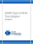
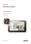
Auxiliary Control Test Adapter User Manual Auxiliary Control Test Adapter User Manual P a g e | 1 © 2011 Wilder Technologies, LLC Document No. 910‐0015‐000 Rev. C Auxiliary Control Test Adapter User Manual Table of Contents Introduction ..................................................................................................................................... 3 Product Inspection .......................................................................................................................... 4 The Auxiliary Control Test Adapter Care and Handling Precautions ............................................... 5 General Test Adapter, Cable, and Connector .................................................................................. 7 Handling and Storage .................................................................................................................. 7 Visual Inspection.......................................................................................................................... 7 Cleaning ....................................................................................................................................... 7 Making Connections .................................................................................................................... 7 Electrostatic Discharge Information ................................................................................................ 8 Mechanical and Environmental Specifications................................................................................ 9 Electrical Specifications ................................................................................................................. 12 Auxiliary Control Test Adapter User Model .................................................................................. 13 Auxiliary Control Test Adapter Reference Information ................................................................. 19 Wilder Technologies, LLC – Limited Warranty .............................................................................. 22 Wilder Technologies, LLC – Terms & Conditions of Sale ............................................................... 23 Compliance with Environmental Legislation ................................................................................. 24 WEEE Compliance Statement .................................................................................................... 24 Glossary of Terms (DisplayPort) .................................................................................................... 25 Glossary of Terms (HDMI) ............................................................................................................. 26 Index .............................................................................................................................................. 27 P a g e | 2 © 2011 Wilder Technologies, LLC Document No. 910‐0015‐000 Rev. C Auxiliary Control Test Adapter User Manual Introduction This user’s guide documents the Auxiliary Control Test Adapter (DPI‐TPA‐A) as used with DisplayPort products. The Auxiliary Control Test Adapter, when paired with the DPI Plug or Receptacle TPA or mDPI Plug or Receptacle, can be used for Dual Mode operation, for tethered cable emulation, manual operation of HPD, local +3.3V generation, as well as connection to a Quantum Data 882 DisplayPort Analyzer or a Tektronix Aux Controller. An EEPROM socket is provided to support dual‐mode operations. Contact Wilder Technologies for future support of the dual‐mode EEPROM. When paired with the DP Plug or Receptacle TPA, or mDP Plug or Receptacle TPA, it can be used for manual operation of HPD, local +3.3V generation, as well as connection to a Quantum Data 882 DisplayPort Analyzer or a Tektronix Aux Controller. Figure 1. The Auxiliary Control Test Adapter.
NOTE: DPI and mDPI TPAs support dual mode and tethered cable as well as standard DisplayPort operation. DP and mDP TPAs are configured for DisplayPort operation only, they do not support dual mode or tethered cable operation. The adapter cable assembly supplied with each DPI‐TPA‐A (P/N 415‐0040‐000) maybe used to convert a standard DP‐TPA product with 4 position keyed and latching connectors to the 6 position keyed and latching connector that mates with the Auxiliary Control Test Adapter. Contact Wilder Technologies or visit the Wilder Technologies web site for additional information. P a g e | 3 © 2011 Wilder Technologies, LLC Document No. 910‐0015‐000 Rev. C Auxiliary Control Test Adapter User Manual Also provided with each DPI‐TPA‐A Auxiliary Control Test Adapter are spare connector parts and contacts to allow user defined interface wiring to the test adapter. 1.
(1) 3 position connector housing, receptacle, (Molex number 43645‐0300). 2.
(1) 6 position connector housing, receptacle, (Molex number 43645‐0600). 3.
(9) Female receptacle contacts, 26‐30awg (Molex number 43030‐0011). Replacement plug/receptacle parts can be purchased through Molex distributors. Product Inspection Upon receiving the Auxiliary Control Test Adapter from Wilder Technologies, perform the following product inspection:
Inspect the outer shipping container, foam‐lined instrument case, and product for damage. Retain the outer cardboard shipping container until the contents of the shipment have been inspected for completeness and the product has been checked mechanically and electrically. Use the foam‐lined instrument‐case for secure storage of the Wilder Technologies Auxiliary Control Test Adapter when not in use. Locate the shipping list and verify that all items ordered were received. In the unlikely event that the product is defective or incomplete, the “Limited Warranty” section discusses how to contact Wilder Technologies for technical assistance and/or how to package the product for return. P a g e | 4 © 2011 Wilder Technologies, LLC Document No. 910‐0015‐000 Rev. C Auxiliary Control Test Adapter User Manual The Auxiliary Control Test Adapter Care and Handling Precautions When using the Auxiliary Control Test Adapter with DisplayPort Plug or Receptacle test adapters careful handling is required to avoid damage. Improper handling techniques, or using too small a cable bend radius, can damage the coaxial cable connections within the adapter housing or the cables themselves. This can occur at any point along the cable. To achieve optimum performance and to prolong the Auxiliary Control Test Adapter and DisplayPort TPA’s life, observe the following handling precautions:
CAUTION 1: Avoid Torque Forces (Twisting) While individual coaxial cables within the test adapter have some rotational freedom, twisting the DisplayPort TPA as a unit, with one end held stationary, in excess of +/‐ 90° may damage or severely degrade performance. Adherence to Caution 5 (below) helps to avoid exceeding twist limits. CAUTION 2: Avoid Sharp Cable Bends Never bend coaxial cables into a radius of 26 mm (1‐inch) or less. Never bend cables greater than 90°. Single or multiple cable bends must be kept within this limit. Bending the DisplayPort TPA cables less than a 26mm (1‐Inch) radius will permanently damage or severely degrade test adapter performance. CAUTION 3: Avoid Cable Tension (Pull Forces) Never apply tension (pull forces) to an individual coaxial cable that is greater than 2.3 kg (5 lbs.). To avoid applying tension, always place accessories and equipment on a surface that allows adjustment to eliminate tension on the DisplayPort TPA and cables. Use adjustable elevation stands or apparatus to accurately place and support the DisplayPort TPA. CAUTION 4: Connect the DisplayPort TPA First To prevent twisting, bending, or applying tension to the coaxial cables when connecting a DisplayPort TPA, always attach the DisplayPort TPA to the device under test (DUT) or cable under test before attaching any SMA connectors. Carefully align the DisplayPort connectors and then gently push the connectors together until fully seated. If the DisplayPort TPA must be turned or twisted to make connection to the DUT, avoid using the DisplayPort TPA housing alone to make this occur. Try to distribute the torque forces along the length of the test setup and cabling. If this is not possible, it is recommended to first loosen or disconnect the SMA connections at the DisplayPort TPA, make the connection to the DUT and then re‐tighten or attach the test equipment leads. NOTE: Only grip the test adapter housing when inserting or extracting the DisplayPort TPA to or from the DUT. Pulling directly on the DisplayPort TPA cables or using them to insert the DisplayPort TPA may cause damage. P a g e | 5 © 2011 Wilder Technologies, LLC Document No. 910‐0015‐000 Rev. C Auxiliary Control Test Adapter User Manual
CAUTION 5: Carefully Make SMA Connections To connect the DisplayPort TPA SMA connectors, follow these steps: 1.
Hold the cable stationary by grasping the cable at the black heat‐shrink section near the SMA connector. 2.
Insert the mating SMA barrel and hand‐tighten the free‐spinning SMA nut onto the connector while avoiding pulling, bending, or twisting the DisplayPort TPA coaxial cable. 3.
The Auxiliary Control Test Adapter and DisplayPort TPA SMA connectors have flats that accept an open‐end 1/4‐inch or 6.5mm wrench. When attaching instrument cables to these test adapters, it is recommended that the SMA connectors be mechanically held and the test leads be tightened to the equipment manufacturer’s torque recommendations, normally 5 in‐lbs, using a 5/16‐inch open‐end wrench. If the test set‐up requires repositioning, first loosen or disconnect the SMA connections to avoid twisting, bending, or tension. NOTE: A drop in signal amplitude by half or 6db during the testing of a lane may indicate that a cable has been mechanically pulled free of coaxial cable connections internal to the assembly. This could be determined by checking if the cable has any lateral play relative to the TPA. This would only occur when the TPA has exceeded the pull force as specified within the mechanical specification. If the cable cannot be re‐seated, the test adapter will need to be sent back to the factory for service.
CAUTION 6: Independently Support Instrument Cables or Accessories Excessive weight from instrument cables and/or accessories connected to the Auxiliary Control Test Adapter or DisplayPort TPA can cause damage or affect the test adapter performance. Be sure to provide appropriate means to support and stabilize all test set‐up components. P a g e | 6 © 2011 Wilder Technologies, LLC Document No. 910‐0015‐000 Rev. C Auxiliary Control Test Adapter User Manual General Test Adapter, Cable, and Connector Observing simple precautions can ensure accurate and reliable measurements. Handling and Storage Before each use of the Auxiliary Control Test Adapter, ensure that all connectors are clean. Handle all cables carefully and store the test adapter in the foam‐lined instrument case when not in use, if possible. Do not set connectors contact end down. Install the SMA protective end caps when the test adapter is not in use. Visual Inspection Be sure to inspect all cable connectors carefully before making a connection. Inspect all cables for metal particles, scratches, deformed threads, dents, or bent, broken, or misaligned SMA connector center conductors. Do not use damaged cables. Cleaning If necessary, clean the connectors using low‐pressure (less than 60 PSI) compressed air or nitrogen with an effective oil‐vapor filter and condensation trap. Clean SMA connector threads, if necessary, using a lint‐free swab or cleaning cloth moistened with isopropyl alcohol. Always completely dry a connector before use. Do not use abrasives to clean the connectors. Re‐
inspect connectors, making sure no particles or residue remains. Making Connections Before making any connections, review the “Care and Handling Precautions” section. Follow these guidelines when making connections:
Align cables carefully Make preliminary connections lightly To tighten SMA connections, turn connector nut only Do not apply bending force to coaxial cables Do not over‐tighten preliminary connections Do not twist or screw‐in cables For SMA connections, use a torque wrench, and do not tighten past the “break” point of the torque wrench P a g e | 7 © 2011 Wilder Technologies, LLC Document No. 910‐0015‐000 Rev. C Auxiliary Control Test Adapter User Manual Electrostatic Discharge Information Protection against electrostatic discharge (ESD) is essential while connecting, inspecting, or cleaning the Auxiliary Control Test Adapter and connectors when attached to a static‐sensitive circuit (such as those found in test sets). Electrostatic discharge can damage or destroy electronic components. Be sure to perform all work on electronic assemblies at a static‐safe work station, using two types of ESD protection:
Conductive table‐mat and wrist‐strap combination Conductive floor‐mat and heel‐strap combination When used together, both of these types provide a significant level of ESD protection. Used alone, the table‐mat and wrist‐strap combination provide adequate ESD protection. To ensure user safety, the static‐safe accessories must provide at least 1 MΩ of isolation from ground. Acceptable ESD accessories may be purchased from a local supplier. WARNING: These techniques for a static‐safe work station should not be used when working on circuitry with a voltage potential greater than 500 volts. P a g e | 8 © 2011 Wilder Technologies, LLC Document No. 910‐0015‐000 Rev. C Auxiliary Control Test Adapter User Manual Mechanical and Environmental Specifications NOTE: All specifications in this manual are subject to change. Table 1. General Specifications
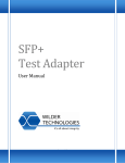
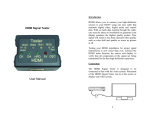
ITEM DESCRIPTION Usage Environment Controlled indoor environment Test Adapter Length x Width x Height 83.3 mm (3.28 in) x 46.5 mm (1.83 in) x 14.2 mm (0.56 in) Operating Temperature 0°C to +55°C (32°F to +131°F) (Characteristic) Storage Temperature ‐40°C to +70°C (‐40°F to +158°F) (Characteristic) Source power input via test points or optional 3‐position Molex connector for providing external +3.3V. I/O connection from TPA for Aux signals when used in Dual Mode. Input low‐speed connection from TPA (6‐position Molex connector). USB Type A power input connection. (Required for local +3.3V generation. Jumper Park for spare jumpers. Can be used for low‐speed connection or probing I/O low‐speed connection (DisplayPort receptacle connector) for connection to Quantum Data 882. Auxiliary low‐speed I/O connection (6‐position Molex connector) for connection to Tektronix Auxiliary Controller. Figure 2. Connectors (Auxiliary Control Test Adapter shown)
Auxiliary Control Test Adapter Pin‐out The Auxiliary Control Test Adapter has three low‐speed connectors, a DisplayPort Connector, a USB connector, and two SMA connectors. Of the three low‐speed connectors, one is for connection of the DisplayPort TPA, one of which can be used to connect to the Tektronix Auxiliary Controller, and the third for any probing and/or parked jumpers. Labels clearly mark each position of the three low‐speed connectors. The DisplayPort connector is for connection of the Quantum Data 882 DisplayPort Analyzer. The USB connector provides power to the LDO for local generation of 3.3V. The two SMA connectors are for connection of the Aux signals for Dual Mode operation. The following figure refers to pin‐description tables for each of the connector types. P a g e | 9 © 2011 Wilder Technologies, LLC Document No. 910‐0015‐000 Rev. C Auxiliary Control Test Adapter User Manual Table 2. Pin Assignments for Low-Speed Connectors J1, J2, and J12
PIN (J1 & J2) PIN (J12) SIGNAL IDENTIFICATION DESCRIPTION 1 2 HPD Hot Plug Detect 2 4 PWR DP_PWR, DisplayPort Power 3 6 RTN Return, DisplayPort Power Return 4 8 GND Ground 5 10 CAD 6 12 CEC Cable Adapter Detect, DP configuration pin 13 Consumer Electronics Control, DP configuration pin 14 Table 3. Pin Assignments for SMA Connector J10
PIN SIGNAL IDENTIFICATION COLOR CODE DESCRIPTION 1 Aux_n Green Aux CH(n), can be jumpered to SDA shield GND Green Ground Table 4. Pin Assignments for SMA Connector J11
PIN SIGNAL IDENTIFICATION COLOR CODE DESCRIPTION 1 Aux_p Green Aux CH(p), can be jumpered to SCL shield GND Green Ground Table 5. Pin Assignments for USB Connector J13
PIN SIGNAL IDENTIFICATION DESCRIPTION 1 Vbus 2 D‐ Data (n), not connected 3 D+ Data (p), not connected 4 RTN Return, (connected to Ground) Connector Shell None NC +5V power supply P a g e | 10 © 2011 Wilder Technologies, LLC Document No. 910‐0015‐000 Rev. C Auxiliary Control Test Adapter User Manual Table 6. Pin Assignments for DisplayPort Connector J8
Connector Pin Number Destination ML Lane 0 (p) – Source ML Lane 3 (n) – Sink 1 NC Ground 2 Ground ML Lane 0 (n) – Source ML Lane 3 (p) – Sink 3 NC ML Lane 1 (p) – Source ML Lane 2 (n) – Sink 4 NC Ground 5 Ground ML Lane 1 (n) – Source ML Lane 2 (p) – Sink 6 NC ML Lane 2 (p) – Source ML Lane 1 (n) – Sink 7 NC Ground 8 Ground ML Lane 2 (n) – Source ML Lane 1 (p) – Sink 9 NC ML Lane 3 (p) – Source ML Lane 0 (n) – Sink 10 NC Ground 11 Ground ML Lane 3 (n) – Source ML Lane 0 (p) – Sink 12 NC Config 1 (CAD) 13 J1‐5, J2‐5, J6‐1 & 3, J7‐2, J12‐10 Config 2 (CEC) 14 J1‐6, J2‐6, J7‐1, 3, & 5, J12‐12 AUX CH (p) 15 J4‐1, J11‐Sig, Ground 16 Ground AUX CH (n) 17 J3‐1, J10‐Sig, HPD, Hot Plug Detect 18 J1‐1, J2‐1, J5‐2, J12‐2 RTN, Return DP_PWR 19 RTN PLANE DP_PWR 20 TP2, J1‐2, J2‐2, J6‐2, J9‐2, J12‐4, J14‐2 & 4 None NC Pin Description Connector Shell P a g e | 11 © 2011 Wilder Technologies, LLC Document No. 910‐0015‐000 Rev. C Auxiliary Control Test Adapter User Manual Electrical Specifications NOTE: All specifications in this manual are subject to change. Table 7. Auxiliary Control Test Adapter Electrical Specifications
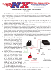
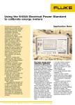
SPECIFICATION MINIMUM TYPICAL MAXIMUM Vcc (V) 2.5 5.0 5.5 Required by EEPROM Icc (mA) 5.3 With EEPROM, SDA = SDC = 0V HPD current (mA), Vhpd = 3.3V 3.1 CEC current (µA), Vcec = 3.3V 136 NOTES P a g e | 12 © 2011 Wilder Technologies, LLC Document No. 910‐0015‐000 Rev. C Auxiliary Control Test Adapter User Manual Auxiliary Control Test Adapter User Model The Auxiliary Control Test Adapter contains jumpers that easily configure the low‐speed signal lines for several test conditions listed in the VESA DisplayPort™ Interoperability Guideline. Test points are also provided for easy measurement access. Specific features and usage models are presented in this section. The Jumper Park block array is used for storage of jumpers when not in use. 5 spare jumpers are provided on this block. Figure 3. Auxiliary Control Test Adapter (DPI-TPA-A) Figure 4. mDPI-TPA-P (Plug Test Adapter) mated to a DPI-TPA-A (Auxiliary Control Test Adapter)
P a g e | 13 © 2011 Wilder Technologies, LLC Document No. 910‐0015‐000 Rev. C Auxiliary Control Test Adapter User Manual The following pages details and illustrates the jumper positions for normal operation, manual reset, local DP_PWR generation, tethered cable, and dual mode. Tether cable and dual mode are only supported with DPI or mDPI TPAs. Local DP_PWR generation uses a USB connection to provide Power, the use of the HPD and CEC circuitry for testing, and source testing of the E‐
EDID with the 80h/81h (offset to A0h) address modification for DDC buffer ID. Most HDMI tests require interaction with the E‐EDID to setup the HDMI protocol to the necessary state for testing. NOTE: The Auxiliary Control Test Adapter does not provide for testing HDCP functionality. An external data generator must be used to test this functionality. The following are examples of setups for test. They are included to explain the operation of the Auxiliary Control Test Adapter. They are not meant to replace the most recent version of the CTS. Please follow the requirements of the most recent version for the CTS. Table 8. Auxiliary Control Test Adapter General and Specific Jumpers
CONNECTOR POSITION 1‐2 POSITION 3‐4 POSITION 5‐6 NOTES J3 AUX_n to SDA Clock for the EEPROM J4 AUX_p to SCL Data for the EEPROM J5 Short HPD Manual reset J6 Dual mode 50 ohm to gnd Config pin 13 J7 Tethered cable Dual Mode J14 DP_PWR connect Local 3.3V to DP_PWR 50 ohm to gnd Config pin 14 P a g e | 14 © 2011 Wilder Technologies, LLC Document No. 910‐0015‐000 Rev. C DP_PWR Auxiliary Control Test Adapter User Manual Figure 5. Auxiliary Control Test Adapter connected for normal DP testing.
Note: The jumper on J14 pins 1‐2 is connecting DP_PWR from J1 through to the rest of the test fixture. J6 pins 3‐4 connects Config 1 pin 13 of DisplayPort connector to ground through 50 ohms. J7 pins 5‐6 connects Config 2 pin 14 of DisplayPort connector to ground through 50 ohms. These two connections may not be required but are called out in the VESA DisplayPort CTS 1.1a specification, dated Oct 26, 2009, on page 22. NOTE: DPI and mDPI TPAs support dual mode and tethered cable as well as standard DisplayPort operation. DP and mDP TPAs are configured for DisplayPort operation only, they do not support dual mode or tethered cable operation. P a g e | 15 © 2011 Wilder Technologies, LLC Document No. 910‐0015‐000 Rev. C Auxiliary Control Test Adapter User Manual Figure 6. Auxiliary Control Test Adapter in Reset
Note that jumper J5 is used to manual set HPD to ground. This can be used to reset normal DP operation or Dual Mode (as HDMI). The above drawing shows the other jumpers set for the normal testing of the previous example. Figure 7. Local 3.3V connected to DP_PWR, isolated from the DUT, on the DPI-TPA-A
Note that jumpering J14 pins 3‐4 is used to connect the local 3.3V power supply to the test DPI‐TPA‐A. This can be used for test conditions that require a stable power supply. For source and sink testing DP_PWR needs to be isolated from the DUT. Hence, J14 pins 1‐2 would not have a jumper. The rest of the jumpers are set for normal testing of the first example. P a g e | 16 © 2011 Wilder Technologies, LLC Document No. 910‐0015‐000 Rev. C Auxiliary Control Test Adapter User Manual Figure 8. Local 3.3V connected to DP_PWR, as well as connected to the DUT, on the DPI-TPA-A
For active cable testing, an additional jumper on J14 pins 1‐2 would be required. Passive cable testing may wish to use the jumper on J14 pins 1‐2 to determine isolation. The rest of the jumpers are set for normal testing of the first example. WARNING: The Auxiliary Control Test Adapter is designed for voltages less than 42 V rms. It is not to be used for HI‐pot testing. P a g e | 17 © 2011 Wilder Technologies, LLC Document No. 910‐0015‐000 Rev. C Auxiliary Control Test Adapter User Manual Figure 9. Jumper position that indicates a tethered cable on the Auxiliary Control Test Adapter. DPI or
mDPI TPAs only. DP and mDP TPAs are internally configured for DisplayPort Operation. Note that jumpering J7 pins 1‐2 is used to indicate a tethered cable to the DUT. Any of the previous tests can be run with the tethered cable set. The jumper on J14 pins 1‐2 is connecting DP_PWR from J1 through to the rest of the test fixture as in the first example. P a g e | 18 © 2011 Wilder Technologies, LLC Document No. 910‐0015‐000 Rev. C Auxiliary Control Test Adapter User Manual Figure 10. Jumper positions for Dual Mode (HDMI only) on the Auxiliary Control Test Adapter. DPI or
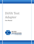
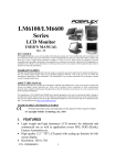
mDPI TPAs only. DP and mDP TPAs are internally configured for DisplayPort Operation. Note that jumpering J3 and J4 Connects the Aux_n and Aux_p to SDA and SCL respectively. Jumpering J6 pins 1‐2 is used to pull up the Config 1 pin 13 of the DisplayPort connector which indicates to the DUT that a Cable adapter is connected. Jumpering J7 pins 3‐4 makes the diode pull‐up on Config 2 pin 14 of the DisplayPort connector creating the CEC pull‐up. J5 and J14 are don’t cares. The above picture shows additional jumpers on j14 pins 1‐2 for external DP_PWR from the DUT. Auxiliary Control Test Adapter Reference Information This section contains an illustration of the Auxiliary Control Test Adapter, the schematic, primary cable attachment detail, secondary cable attachment for attachment to a Tektronix Auxiliary Controller, secondary cable attachment for testing with a Quantum Data 882 DisplayPort Analyzer, and specification of the Auxiliary Control Test Adapter. P a g e | 19 © 2011 Wilder Technologies, LLC Document No. 910‐0015‐000 Rev. C Auxiliary Control Test Adapter User Manual J12 NC NC NC NC NC NC
J1 HPD PWR RTN GND CAD
CEC 1 2 3 4 5 6 7 8 9 10 11 12 HPD PWR RTN GND CAD
CEC DP AUX control TPA 102‐1039‐000 J2
1 1
2 1 2 2
3 3 4 3
4 +3.3V 5 4
J14 5
6 6
100 kohm
J6
1
2
3
4
CAD
J11 SMA AUX_p SCL J4 1 49.9 ohm
1 kohm
2 1 Mohm J5 SMA J10 AUX_n J3 1 2 1 SDA 2 HPD 1 Mohm
1 Mohm
J9
TP1 3
2
1 Mohm J7
Config pin 13
J8
19 1 20 2 27 kohm mmbd914 1
2
3
4
5
6
TP2 CEC
49.9 ohm
.01uf
Config pin 14
HPD
DP_PWR
22uf P a g e | 20 © 2011 Wilder Technologies, LLC Document No. 910‐0015‐000 Rev. C 1
Auxiliary Control Test Adapter User Manual SCL
49.9 ohm SDA
49.9 ohm U1
10 kohm
DP_PWR
24LC08B 1 A0 Vcc 8 10 kohm 10 kohm 2 A1 WP 7 10 kohm 2 kohm 3 A3 SCL 6 2 kohm 4 Vss SDA 5 4.7 pF
DP_PWR
4.7 pF .01uf
U2 +5V J13 PWR
D‐ D+ GND 1 LT1117‐3.3 Vin Vout +3.3V Gnd 2 3 4 .01uf +3.3V +3.3V 0 ohm +5V
+5V
2 2uf Figure 11. Auxiliary Control Test Adapter Schematic P a g e | 21 © 2011 Wilder Technologies, LLC Document No. 910‐0015‐000 Rev. C .01uf
22uf
Auxiliary Control Test Adapter User Manual Wilder Technologies, LLC – Limited Warranty Wilder Technologies, LLC warrants that each Test Adapter, 1) is free from defects in materials and workmanship and, 2) conforms to Wilder Technologies specifications for a period of 12 months. See Consumable and Fragile Material Warranty for exceptions to the 12 month warranty The warranty period for a Test Adapter is a specified, fixed period commencing on the date of ship from Wilder Technologies, LLC. If you did not purchase your Test Adapter directly from Wilder Technologies, LLC, the serial number and a valid proof of purchase will be required to establish your purchase date. If you do not have a valid proof of purchase, the warranty period will be measured from the date of ship from Wilder Technologies, LLC. If, during the warranty period, the Test Adapter is not in good working order, Wilder Technologies, LLC will, at its option, repair or replace it at no additional charge, except as is set forth below. In some cases, the replacement Test Adapter may not be new and may have been previously installed. Regardless of the Test Adapter’s production status, Wilder Technologies, LLC appropriate warranty terms apply. Consumable and Fragile Material Warranty Wilder Technologies, LLC warrants that consumable materials and all fragile materials supplied by Wilder Technologies, LLC either as part of an instrument or system, or supplied separately, will be free from defects in material and workmanship at the time of shipment. Extent of Warranty The warranty does not cover the repair or exchange of a Test Adapter resulting from misuse, accident, modification, unsuitable physical or operating environment, improper maintenance by you, or failure caused by a product for which Wilder Technologies, LLC is not responsible. The warranty is voided by removal or alteration of Test Adapter or parts identification labels. The initial three months are unconditional; the remaining months excludes plugs, receptacles and SMA connectors. Connectors are wear items and excluded from the warranty after the initial three months. These warranties are your exclusive warranties and replace all other warranties or conditions, express or implied, including but not limited to, the implied warranties or conditions or merchantability and fitness for a particular purpose. These warranties give you specific legal rights and you may also have other rights which vary from jurisdiction to jurisdiction. Some jurisdictions do not allow the exclusion or limitation of express or implied warranties, so the above exclusion or limitation may not apply to you. In that event, such warranties are limited in duration to the warranty period. No warranties apply after that period. Items Not Covered by Warranty
Wilder Technologies, LLC does not warrant uninterrupted or error‐free operation of a Test Adapter. Any technical or other support provided for a Test Adapter under warranty, such as assistance via telephone with "how‐to" questions and those regarding Test Adapter set‐up and installation, will be provided WITHOUT WARRANTIES OF ANY KIND. Warranty Service Warranty service may be obtained from Wilder Technologies, LLC by returning a Wilder Technologies, LLC Returns Material Authorization and the Test Adapter to Wilder Technologies, LLC during the warranty period. To obtain RMA number, contact support@wilder‐tech.com. You may be required to present proof of purchase or other similar proof of warranty entitlement. You are responsible for any associated transportation charges, duties and insurance between you and Wilder Technologies, LLC. In all instances, you must ship Test Adapters in Wilder Technologies, LLC approved packaging. Information on packaging guidelines can be found at: www.wilder‐tech.com. Wilder Technologies, LLC will ship repaired or replacement Test Adapter Delivery Duty Prepaid (DDP) and will pay for return shipment. You will receive title to the repaired or replacement Test Adapter and you will be the importer of record. P a g e | 22 © 2011 Wilder Technologies, LLC Document No. 910‐0015‐000 Rev. C Auxiliary Control Test Adapter User Manual Wilder Technologies, LLC – Terms & Conditions of Sale 1.
2.
3.
4.
5.
6.
Other Documents: This Agreement may NOT be altered, supplemented, or amended by the use of any other document(s) unless otherwise agreed to in a written agreement signed by both you and Wilder Technologies, LLC. If you do not receive an invoice or acknowledgement in the mail, via e‐mail, or with your Product, information about your purchase may be obtained at support@wilder‐tech.com or by contacting your sales representative. Payment Terms, Orders, Quotes, Interest: Terms of payment are within Wilder Technologies, LLC’s sole discretion, and unless otherwise agreed to by Wilder Technologies, LLC, payment must be received by Wilder Technologies, LLC prior to Wilder Technologies, LLC’s acceptance of an order. Payment for the products will be made by credit card, wire transfer, or some other prearranged payment method unless credit terms have been agreed to by Wilder Technologies, LLC. Invoices are due and payable within the time period noted on your invoice, measured from the date of the invoice. Wilder Technologies, LLC may invoice parts of an order separately. Your order is subject to cancellation by Wilder Technologies, LLC, in Wilder Technologies, LLC’s sole discretion. Unless you and Wilder Technologies, LLC have agreed to a different discount, Wilder Technologies, LLC’s standard pricing policy for Wilder Technologies, LLC‐branded systems, which includes hardware, software and services in one discounted price, allocates the discount off list price applicable to the service portion of the system to be equal to the overall calculated percentage discount off list price on the entire system. Wilder Technologies, LLC is not responsible for pricing, typographical, or other errors in any offer by Wilder Technologies, LLC and reserves the right to cancel any orders resulting from such errors. Shipping Charges; Taxes; Title; Risk of Loss: Shipping, handling, duties and tariffs are additional unless otherwise expressly indicated at the time of sale. Title to products passes from Wilder Technologies, LLC to Customer on shipment from Wilder Technologies, LLC’s facility. Loss or damage that occurs during shipping by a carrier selected by Wilder Technologies, LLC is Wilder Technologies, LLC’s responsibility. Loss or damage that occurs during shipping by a carrier selected by you is your responsibility. You must notify Wilder Technologies, LLC within 7 days of the date of your invoice or acknowledgement if you believe any part of your purchase is missing, wrong or damaged. Unless you provide Wilder Technologies, LLC with a valid and correct tax exemption certificate applicable to your purchase of Product and the Product ship‐to location, you are responsible for sales and other taxes associated with the order. Shipping dates are estimates only. WARRANTY: WILDER TECHNOLOGIES, LLC, warrants that the item(s) manufactured under the Buyer’s contract shall be free from defects in materials and workmanship furnished by WILDER TECHNOLOGIES, LLC, and shall conform to the applicable drawings and specifications. WILDER TECHNOLOGIES, LLC’S liability herein, for breach of warranty, contract or negligence in manufacturing, shall be limited to repair or replacement. Repair or replacement of defective items will be applicable only if the Buyer notifies WILDER TECHNOLOGIES, LLC, by written notice within 30‐days of delivery. All claims shall be addressed to: support@wilder‐tech.com or WILDER TECHNOLOGIES, LLC, 6101A East 18th Street, Vancouver, Washington 98661 U.S.A.; ATTENTION: Customer Service Manager. WILDER TECHNOLOGIES, LLC, reserves the right to inspect at the Buyer’s plant all items claimed to be defective or nonconforming prior to authorizing their return. WILDER TECHNOLOGIES, LLC, assumes no liability for the results of the use of its components in conjunction with other electric, electronic or mechanical components, circuits and/or systems. The foregoing constitutes the sole and exclusive remedy of the Buyer and the exclusive liability of WILDER TECHNOLOGIES, LLC, and is IN LIEU OF ANY AND ALL OTHER WARRANTIES, STATUTORY, IMPLIED OR EXPRESSED AS TO MERCHANTABILITY, FITNESS FOR THE PURPOSE SOLD, DESCRIPTION, QUALITY, and PRODUCTIVENESS OR ANY OTHER MATTER. Without limiting the foregoing, in no event shall WILDER TECHNOLOGIES, LLC, be liable for loss of use, profit or other collateral, or for special and/or consequential damages. RETURNED GOODS: WILDER TECHNOLOGIES, LLC, will accept only those goods for return that have been authorized for return. All goods authorized for return shall be assigned a Returned Material Authorization (RMA) Number. The RMA Number shall be clearly marked on the shipping container(s) and all documentation accompanying the goods authorized for return. The RMA Number shall be assigned by WILDER TECHNOLOGIES, LLC pursuant to the conditions set forth in Paragraph 4, WARRANTY. UNITED STATES GOVERNMENT CONTRACTS: In the event this offer is accepted under Government contract, WILDER TECHNOLOGIES, LLC, agrees to accept clauses required by Government regulations and to waive WILDER TECHNOLOGIES, LLC conditions inconsistent therewith. WILDER TECHNOLOGIES, LLC, certifies that it is a regular manufacturer or dealer of the goods and/or services offered herein and that the prices offered do not exceed those charged to any customer for like quantities, services or materials under the same conditions. P a g e | 23 © 2011 Wilder Technologies, LLC Document No. 910‐0015‐000 Rev. C Auxiliary Control Test Adapter User Manual Compliance with Environmental Legislation Wilder Technologies, LLC, is dedicated to complying with the requirements of all applicable environmental legislation and regulations, including appropriate recycling and/or disposal of our products. WEEE Compliance Statement The European Union adopted Directive 2002/96/EC on Waste Electrical and Electronic Equipment (WEEE), with requirements that went into effect August 13, 2005. WEEE is intended to reduce the disposal of waste from electrical and electronic equipment by establishing guidelines for prevention, reuse, recycling and recovery. Wilder Technologies has practices and processes in place to conform to the requirements in this important Directive. In support of our environmental goals, effective January 1st, 2009 Wilder Technologies, LLC has partnered with E‐Tech Recycling of Beaverton, Oregon, www.etechrecycling.com, to recycle our obsolete and electronic waste in accordance with the European Union Directive 2002/96/EC on waste electrical and electronic equipment ("WEEE Directive"). As a service to our customers, Wilder Technologies is also available for managing the proper recycling and/or disposal of all Wilder Technologies products that have reached the end of their useful life. For further information and return instructions, contact support@wilder‐tech.com. P a g e | 24 © 2011 Wilder Technologies, LLC Document No. 910‐0015‐000 Rev. C Auxiliary Control Test Adapter User Manual Glossary of Terms (DisplayPort) TERMINOLOGY DEFINITION Aggressor A signal imposed on a system (i.e., cable assembly) to measure response on
other signal carriers. AUX Channel Half‐duplex, bi‐directional channel between the DisplayPort transmitter and
DisplayPort receiver. Consists of one differential pair transporting self‐clocked data. The DisplayPort AUX Channel supports a bandwidth of 1Mbps over the DisplayPort link. DisplayPort Source is the master that initiates an AUX Channel transaction. DisplayPort Sink is the slave that replies to the AUX Channel transaction initiated by the Requester. Box‐to‐box connection DisplayPort link between two boxes detachable by an end user. A DisplayPort
cable‐connector assembly for the box‐to‐box connection shall have four Main Link lanes. DDC/CI Display Data Channel/Command Interface (VESA)
DisplayPort Receiver Circuitry that receives the incoming DisplayPort Main Link data. Also contains
the transceiver circuit for AUX Channel. Located in Sink Device and the upstream port of Intermediate Device. DisplayPort Transmitter Circuitry that transmits the DisplayPort Main Link data. Also contains the
transceiver circuit for AUX CH. Located in Source Device and in the downstream port of Intermediate Device. DP‐TPA DisplayPort Test Point Access. A specialized assembly that interfaces to a DisplayPort receptacle or plug and enables access of signals for measurement or stimulation. Dual‐standard Device Source or Sink Device that supports both DisplayPort and DVI/HDMI operating modes.
Informative The designation of a test that is not required for compliance but is considered
important from a characterization standpoint. It is provided for informational purposes only. Main Link Unidirectional channel for isochronous stream transport from DisplayPort
Source to DisplayPort Sink. Consists of one, 2, or 4 lanes, or differential pairs. Supports 2 bit rates: 2.7Gb/s per lane (referred to as “High Bit Rate”) and 1.62Gb/s per lane (referred to as “Reduced Bit Rate”). Normative The designation of a test that is required for compliance. Sink Device A device that contains A/V stream sinks for display and/or sound. Source Device A device that contains a stream source and originates an isochronous A/V
stream. Victim A signal carrier on a system that has a response imposed on it by other signals in the system. P a g e | 25 © 2011 Wilder Technologies, LLC Document No. 910‐0015‐000 Rev. C Auxiliary Control Test Adapter User Manual Glossary of Terms (HDMI) TERMINOLOGY DEFINITION Aggressor A signal imposed on a system (i.e., cable assembly) to measure response on
other signal carriers. ARC Audio Return Channel, used to send an audio stream from the sink to the source or repeater. Box‐to‐box connection HDMI Type‐A link between two boxes detachable by an end user. An HDMI Type‐A cable‐connector assembly for the box‐to‐box connection shall have three TMDS Link lanes. CEC Consumer Electronics Control
DDC Display Data Channel (VESA)
HDMI Ethernet HDMI Ethernet provides a full duplex connection between HDMI devices which conforms to 100Base‐TX IEEE 802.3 standard [4n]. HDMI Type‐A Receiver Circuitry that receives the incoming HDMI Type‐A TMDS Link data. Located in Sink Device and the upstream port of Intermediate Device. HDMI Type‐A Transmitter Circuitry that transmits the HDMI Type‐A TMDS Link data located in Source Device and in the downstream port of Intermediate Device. HDMI‐TPA HDMI Type‐A Test Point Access. A specialized assembly that interfaces to a HDMI Type‐A receptacle or plug and enables access of signals for measurement or stimulation. Dual‐standard Device Source or Sink Device that supports both DisplayPort and DVI/HDMI operating modes.
Informative The designation of a test that is not required for compliance but is considered
important from a characterization standpoint. It is provided for informational purposes only. Normative The designation of a test that is required for compliance. Sink Device A device that contains A/V stream sinks for display and/or sound. Source Device A device that contains a stream source and originates an isochronous A/V
stream. TMDS Transition Minimized Differential Signaling
Victim A signal carrier on a system that has a response imposed on it by other signals in the system. P a g e | 26 © 2011 Wilder Technologies, LLC Document No. 910‐0015‐000 Rev. C Auxiliary Control Test Adapter User Manual Index Adapter Cable Assembly, 3 Auxiliary Control Test Adapter Pin‐out, 9 Auxiliary Control Test Adapter Reference Information, 19 Auxiliary Control Test Adapter User Model, 13 Cable Bend Limits, 5 Cable Tension (Pull Forces), 5 Cable Twisting (Torque), 5 Care and Handling, 5 Cleaning, 7 Compliance WEEE, 24 Connections DP‐TPA to DUT, 5 SMA, 6 Electrical Specifications, 12 Electrostatic Discharge Information (ESD), 8 ESD protection, 8 Example Test Setups DPI‐TPA‐A Connected for Normal DP Testing, 15 DPI‐TPA‐A in Reset, 16 Jumpered for Dual Mode, 18 Local 3.3V Connected to DP_PWR Connected to DUT, 17 Local 3.3V Connected to DP_PWR Isolated from DUT, 16 Tethered Cable Jumper Position, 18 Figures Auxiliary Control Test Adapter, 13 Auxiliary Control Test Schematic, 20, 21 Connectors, 9 DPI‐TPA‐A Connected for Normal DP Testing, 15 DPI‐TPA‐A in Reset, 16 Jumpered for Dual Mode, 18 Local 3.3V Connected to DP_PWR & Connected to DUT, 17 Local 3.3V Connected to DP_PWR Isolated from DUT, 16 mDPI‐TPA‐P mated to a DPI‐TPA‐A, 13 Tethered Cable Jumper Position, 18 The Auxiliary Control Test Adapter (Plug), 3 Glossary, DisplayPort, 25 Glossary, HDMI, 26 Handling and Storage, 7 HDCP Functionality, 14 Jumper Positions Dual Mode, 14 Local DP_PWR Generation, 14 Manual Reset, 14 Normal Operation, 14 Tethered Cable, 14 Jumpers, 13 Low‐speed Connectors, 9 Making Connections, 7 Mechanical and Environmental Specifications, 9 Molex part numbers, 3 Product Inspection, 4 Product Return, 4 Pull Force, 6 Secure Storage, 4 Support, 23 Supporting Instrument Cables or Accessories, 6 Tables DisplayPort Connector J8, 11 DPI‐TPA‐A Electrical Specifications, 12 DPI‐TPA‐A General and Specific Jumpers, 14 General Specifications, 9 Low‐Speed Connectors, 10 SMA Connector (J10), 10 SMA Connector (J11), 10 USB Connector (J13), 10 Terms and Conditions of Sale, 23 VESA DisplayPort™ Interoperability Guideline, 13 Visual Inspection, 7 Warranty, 22 Web Sites support@wilder‐tech.com, 22, 23 www.etechrecycling.com, 24 www.wilder‐tech.com, 22 WEEE, 24 P a g e | 27 © 2011 Wilder Technologies, LLC Document No. 910‐0015‐000 Rev. C Visit our website at www.wilder‐tech.com Wilder Technologies, LLC 6101A East 18th Street Vancouver, WA 98661 Phone: 360‐859‐3041 Fax: 360‐859‐3105 www.wilder‐tech.com © 2011 Wilder Technologies, LLC Document No. 910‐0015‐000 Rev. C Created: 5/3/2011, Revised: 8/22/2012