1
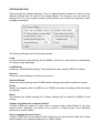
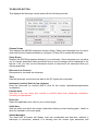
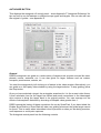
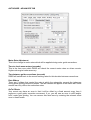
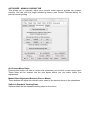
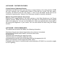
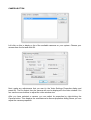
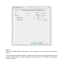
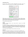
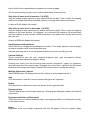
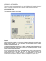
Dave's Solar System Recorder
User Manual
Copyright David Wilson
of
The Window Sill Observatory
http://windowsillobservatory.wordpress.com
Version 4
Table of Contents
INTRODUCTION
WHAT'S NEW
QUICK START GUIDE
MAIN WINDOW
TELESCOPE BUTTON
AUTOGUIDE BUTTON
CAMERA BUTTON
HISTOGRAM BUTTON
EXPOSURES BUTTON
CAPTURE BUTTON
MOSAIC BUTTON
APPENDIX A – EQUIPMENT SETUP
APPENDIX B – SETTINGS FILE LAYOUT
APPENDIX C – CURRENT LIMITATIONS
APPENDIX D – AUTOGUIDER v1
APPENDIX E – SCREENSHOT RECORDER
APPENDIX F – AUTOGUIDE REFERENCE
NEVER LOOK AT THE SUN DIRECTLY OR THROUGH A TELESCOPE WITHOUT
PROPER SAFETY FILTERS!!
INTRODUCTION
Dave's Solar System Recorder (DSSR) is software that can control your telescope and
video camera to capture videos of astro objects.
It is designed to be very simple to use with all commands available via buttons – it has no
menu bar.
DSSR can perform the following actions.
Autoguide on stars, planets, sunspots, solar prominences and active regions, craters.
Capture single videos or sequences of videos for timelapse animations
Capture sequences of videos on several points on the Sun or Moon.
Capture video tiles needed to construct large mosaic images of the Sun or Moon.
Apply multiple exposure settings to each video – e.g. capture solar prominences and
surface features. Multiple exposures can be applied to sequences and mosaics for high
dynamic range (HDR) images and animations.
Autoguide on a third party video window. Useful for non-standard cameras.
Measure tracking errors on your mount.
WHAT'S NEW
NEW in VERSION 3.6
Video pause bug fixed.
Full support for EQMOD pulse guide.
NEW in VERSION 3.0
Three separate autoguide methods.
Autoguide using GEM and Celestron and Skywatcher alt-az mounts.
SmartTrak keeps on target during cloud cover.
Support for parallel processing for faster guide target recognition.
Monitor target drift without applying corrections.
Calibration of scope/camera combination.
Manual control of mount motor rates for precision manual guiding.
Graph window to show guide error and mount tracking error history.
Screen desktop recorder.
Separate stop buttons for mosaic and sequence captures.
Mosaic tile rotate options.
Turn tracking on or off in scope window.
Zoom video window with mouse wheel.
Pulse guide support for EQMOD and Paramount MX mounts.
And lots of bug fixes and other improvements.
DSSR QUICK START INSTRUCTIONS
Install ASCOM Platform
Currently, DSSR needs the ASCOM platform to work. You can install it from here.
Install Microsoft .NET Framework 4
You need the Microsoft .NET Framework 4 on your PC for this software to run. If it is not
already on your PC or you can install it from here.
Download DSSR
Download the DFM zipped package from here and unzip it to your hard drive. Open the
unzipped folder and run the file called DSSRv4.0 (.exe).
Upgrades are posted on the support forum.
This version works on both Windows 32bit and 64bit.
Equipment Preparation (Appendix A)
Install the latest ASCOM drivers for your telescope mount.
Align your mount and connect it to your PC.
Connect your camera to your PC.
Calculate the horizontal and vertical fields of view for your camera/scope (decimal
degrees).
Start Guiding
Launch DSSR, click Camera and select your camera from the list. Right click on Camera
to adjust camera properties. Close camera properties dialog.
Click Telescope>Choose Scope and select your scope. Enter the field of view angles
(decimal degrees).
Click Settings>Folder and choose a permanent folder for capture.
Click Settings>Save as Default.
Click Autoguide.
Left click on a target feature on the video window. DSSR will start guiding on that feature.
If the target feature rapidly moves off screen, select FlipH or FlipV as required.
Fine tune the Autoguide settings and then save your settings in the settings manager.
Start Capturing
Click Capture to display the capture settings and then press Start.
Press Stop to stop capturing.
DSSR MAIN WINDOW
General
The DSSR main window has a toolbar at top and a status bar at bottom. Also, the top title
bar is used to display timestamped messages to the user. The video window is displayed
after you have selected a camera.
The toolbar buttons are arranged in the following groups:
View – recticle and zoom buttons.
Telescope – telescope selector and autoguider controls.
Camera– camera selector, histogram and exposures controls.
Capture – video and mosaic capture controls.
The bottom status bar displays the following (left to right):
Currently loaded settings file
Telescope status.
Mount type.
Side of pier telescope is on.
Autoguider status.
Video window zoom factor.
Current azimuth
Current right ascension.
Current declination.
Video capture progress bar.
Camera mean light level bar and readout (0-2550).
PC system time converted to UT.
Camera status - capturing or live previewing.
Free space on capture disk (GB).
Number of parallel threads in use for guide target recognition.
The main window also has the following buttons.
All Stop
This button will stop all capture and telescope operations. It is repeated on all subwindows for convenience.
Settings
Displays the Settings Manager.
Start Log or Logging
This turns on or turns off DSSR logging.
Recticle
This displays or hides the cross-hair recticle. Right-click on it to change the color. The
centre of the recticle is the exact point at which the telescope is pointing.
Zoom+ (or Mouse Wheel Forward)
Zoom in to the video window. Scroll bars will appear automatically if you zoom beyond the
DSSR window size.
Zoom- (or Mouse Wheel Backward)
Zoom out from the video window.
100%
Sets zoom on the video window to 100%.
Fit
Fits the video window to the limits of the main window.
Snapshot
Left-click this to take a snapshot of the visible portion of the video window which is saved
to the capture folder in PNG format.
Hold down the Shift button while clicking Snapshot to capture the DSSR main window or
the Ctrl button to capture the entire PC screen.
SETTINGS BUTTON
This launches the Settings Manager. This is a powerful feature because it lets you store
different settings files for each of your target objects. For instance, you can have one
settings file for a solar scope looking at prominences and another for capturing Jupiter
timelapse animations.
The Settings Manager has the following controls.
Load
Load a previously saved settings file into DSSR. Useful if you have different combinations
of camera, scope and target.
Load Default
Loads your DSSR default settings. These settings are also used by DSSR on startup.
Save As
Saves the current settings to a file of your choice.
Save As Default
Saves the current settings as the DSSR default settings which will be loaded on startup.
Folder
Specify the capture folder for DSSR to use. DSSR will create sub-folders within this folder
as required.
Reset
This deletes the default settings file. Factory settings will be loaded by DSSR at next
startup.
Capture all videos into a common folder?
If ticked, DSSR will capture all videos into a common folder called Videos in the main
capture folder. Otherwise, the videos will be saved to a Videos folder in the individual
sequence or mosaic folders.
Save a snapshot for each video?
If ticked, DSSR will save a snapshot PNG image from the start of each video into a folder
called Images in the individual sequence or mosaic folders.
Start DSSR log on startup?
If ticked, DSSR will start logging its activities on startup. This log is saved in the capture
folder and is useful for solving problems.
Choose Capture Folder at Startup?
Useful if you use portable drives. This option forces you to select an available drive.
Number of Processor Cores to Use
DSSR can use parallel processing which greatly speeds up the guide target acquisition
routines. DSSR will attempt to use this number of CPU cores but your PC may force it to
use a higher number. For instance, my 8-core processor can only work as 4 or 8 core.
Warning: Prolonged use of all CPU cores may damage your PC.
AutoGuider Version
DSSR has a new autoguider module version 2 that is now used by default. However, you
can use version 1 by selecting this option. See Appendix D.
Save Screenshot Every ? Seconds
DSSR will create a directory called Screenshots in the main capture folder. It will then save
a desktop screenshot image into this folder at the set intervals. See Appendix E for details
of how to use this feature.
Set a value of 1000000 to disable this feature. You can delete the Screenshots folder after
each session.
Status Messages
The status bar at bottom will display the current capture folder and settings file.
Notes.
You should save a default settings file as soon as possible. Otherwise, DSSR will startup
with factory settings.
Many of DSSR's functions (Autoguide, Histogram, Snapshots) use the video window. You
should ensure that it is not hidden by other windows as much as possible. All DSSR
windows have a hide button that you can use to hide it after you have set up its settings.
Snapshots are saved from the visible video window. You should zoom out if you want to
take a snapshot of the whole camera view.
The most important settings for DSSR are the fields of view in the Telescope Control
Panel. These are needed for accurate autoguiding and mosaic capture.
TELESCOPE BUTTON
This displays the telescope control panel with the following controls.
Choose Scope
This displays the ASCOM telescope chooser dialog. Select your telescope from the dropdown and use the Properties button to configure it. Press OK to accept the telescope.
Setup Scope
Displays the ASCOM properties dialog for your telescope. Some telescopes do not allow
you to change properties while connected and an error message will be displayed in the
top bar. If so, you can use the Disconnect button to disconnect the telescope while you
change properties.
Disconnect or Connect
Disconnects or connects the telescope.
Time
Sets the telescope mount time and date to the PC system time and date.
Horizontal (vertical) field of view (degrees)
Enter the horizontal (or vertical) field of view for the current camera/telescope/barlow
combination.
Portrait mode
Tick this if you are using your camera in portrait rather than landscape orientation.
Currently not operational.
Drive rate
Select the applicable drive rate for your current target.
Settle time
Sets the settle time which the scope needs after slewing to start tracking again. Useful to
allow for backlash in the drive gears.
Status Messages
The status bar at bottom will display local site coordinates and date-time, whether a
telescope is connected, whether it is tracking and the current right ascension and
declination coordinates.
Notes
Fields of view are measured in degrees. To convert from arc-minutes to degrees, divide by
60.
Fields of view are very important to DSSR. It uses them during autoguiding and mosaic
captures. There are many free FOV calculators available on the web.
Some telescope mounts do not allow you to read or set the time from your PC. In this
case, the PC system time will be displayed in the status bar.
AUTOGUIDE BUTTON
This displays the autoguide v2 control panel – check Appendix F 'Autoguide Reference' for
tips on how to use its features on different scope types and targets. You can also still use
the original v1 guider – see Appendix D.
General
DSSR's autoguider can guide on a wide variety of targets such as point sources like stars,
planets, moons, asteroids, etc. It can also guide on larger features such as craters,
sunspots, prominences, comets, etc.
You start the autoguider by left clicking on a feature in the video window. Alternatively, you
can guide on a third party video window by using the target selector. To stop guiding, press
the Stop button.
Once you have selected a target, the autoguider searches for it in the current video frame.
It then calculates how far the target has drifted and sends corrections to the telescope's
drive motors to bring the target back to its original position. You can average out the
effects of atmospheric distortion by choosing a Samples value greater than 1.
DSSR records the history of these corrections for use by SmartTrak. If you have ticked the
Enable SmartTrak box, SmartTrak will take over guiding whenever the guide target cannot
be found. This is useful when intermittent cloud is present or when you are doing mosaics,
multi-exposure or multi-point captures.
The Autoguide control panel has the following controls.
AUTOGUIDE - TOP TOOLBAR
Target
This allows you to autoguide on a third party video window. When you press the button a
semi-transparent target selector window opens. You can drag this using its title bar over
the video window to select a guide target. Click Start guiding on the selector to start the
autoguider. The target selector status bar shows you the current target X and Y
coordinates measured from top left of the desktop. Move the slider to adjust the
transparency.
Stop
Stops the DSSR autoguider.
Graph
Opens the graph window that displays the guiding drift history.
Reset
Resets the SmartTrak guiding history logs.
Guide Method
DSSR has 3 autoguide methods – pulse guide, motor guide and goto guide. Pulse guiding
only works on GEM mounts while the other methods work with GEM and Alt-Az mounts. All
of them work by adjusting the mount motors depending on the mean horizontal and
vertical target drifts (mDH and mDV).
Pulse guide works by DSSR sending a correction pulse to each motor. The length of each
pulse is determined by mDH and mDV and the aggression settings. Some mounts also
allow you to set the correction pulse rate using the sliders in the Advanced tab.
Motor guide first checks to see whether mDH is positive or negative. It then adjusts the
horizontal drive rate until mDH changes sign and repeats for the vertical direction. The
amount of adjustment is determined by the Motor Rate Adjustment in the advanced tab
and the relevant aggressions. You may need aggressions of 200 or 300 for this to work
with Alt-Az scopes.
GoTo guiding first measures how far in degrees the target has drifted in each direction. It
then subtracts this from its current position and moves to the new corrected position. The
correction movements are scaled by the relevant aggressions. You can also add fixed
offsets (in pixels) to each move to correct fixed mount errors (see below).
AUTOGUIDE - GUIDING TAB
Swap Time seconds
DSSR will replace the autoguide target with the current best match at this interval. This is
useful if you are guiding on a rapidly changing feature. Too low an interval will result in
DSSR chasing its tail over the solar surface. Set it to 1000000 to disable swapping.
Minimum Similarity
The autoguider assigns a value between 0 and 1000 to the best match it can find for the
guide target. A perfect match is 1000. Use this value to filter out any false matches that
can occur during light cloud, etc.
Target
Specifies the size of the autoguide target square. Larger values slow down the search
routine.
Max Search
Specifies the maximum distance from the target centre to search for the guide target.
Larger values slow down the search routine.
Samples
Atmospheric distortion can cause the guide target to jump around on the video window.
Setting samples to say 4 means that DSSR will average the target drift over 4 consecutive
snapshots. This reduces the corrections that the autoguider needs to make.
FlipH and FlipV
Tick these boxes to reverse the direction of the correction pulses in the horizontal and/or
vertical directions. This compensates for any mirroring introduced by the optical path. Tick
the relevant box if the autoguider immediately sends the target off screen when engaged.
Aggression (Horizontal and Vertical)
Use this to amplify or reduce the effect of the autoguide corrections. For example, 100% is
normal, 50% will halve the corrections and 200% will double them.
Enable SmartTrak (currently for pulse guide only)
If ticked, SmartTrak will automatically take over guiding when the guide target is lost.
SmartTrak uses the autoguide history to maintain guiding when the guide target cannot be
found. This could occur during cloud cover, multiple exposures or moving to a different
monitor point.
AUTOGUIDE - ADVANCED TAB
Motor Rate Adjustment
This is the change in motor rates which will be applied during motor guide corrections.
Time to check axes motors (seconds)
This is the time over which DSSR will check the current motor rates on alt-az mounts.
Higher values give better accuracy.
Time between guide corrections (seconds)
DSSR will switch back to the mount tracking rates for this duration between corrections.
Rate Sliders
There are 2 sliders that control the rate at which the autoguider corrects the telescope
during pulse guiding correction pulses. The rate chosen will appear in the status bar. Some
mounts can only offer a few correction rates.
GoTo Offsets
Your mount may have an error in that it will be offset by a fixed amount every time it
performs a goto guide correction movement. If so, you will see an error in mDH and/or
mDV under goto guiding. You can remove this fixed error by entering the relevant offset
error in these boxes.
AUTOGUIDE - MANUAL GUIDING TAB
This allows you to manually adjust your mount's motor rates to provide very precise
tracking. Use this with the target monitoring feature (see Further Features below) for
precise manual guiding.
Get Current Motor Rates
Pressing this button will start a routine that measures your mount's current motor rates.
These rates will be entered into the rate boxes where you can make further fine
adjustments.
Manual Rate Adjustment Buttons (Plus or Minus)
These buttons will adjust the relevant motor rates by the amount shown in the dropdowns.
Switch to Standard Tracking Rates
Switches back the the standard tracking rates for the mount.
AUTOGUIDE - GRAPHS TAB
Use this to set the options for the history graph window (guess where I kicked the mount)
AUTOGUIDE - FURTHER FEATURES
Scope/Camera Calibration Routine
Hold down the Shift key while you left-click on a target feature in the video window. DSSR
will then calculate your scope/camera fields of view and the correct Flip box status.
Currently, the fields of view are only within +/- 20% of the calculated values and we are
working on improving this. However, the Flip boxes should be correctly calculated.
Monitor Target Drift without Corrections
Right-click on a target feature in the video window or click Start Monitoring in the Target
Selector window. DSSR will follow the target and report the instantaneous and averaged
drifts in the status bar. You can use this feature to check your periodic drive errors and to
aid during drift alignment of your mount. You can also watch the drifts using the Graph
window.
AUTOGUIDE - STATUS MESSAGES
The status bars at bottom will display the following information.
Similarity of target (next closest target above the minimum in brackets)
Horizontal and vertical motor rates or correction drive rates.
Guiding status.
Total time spent searching for target this cycle.
Total time spent on correction pulses this cycle.
Instantaneous horizontal and vertical target drift for this sample (dH, dV).
Mean horizontal and vertical target drift (mDH, mDV).
Correction pulse times in horizontal and vertical directions (E,W,N,S) or correction angles
for GoTo guiding.
CAMERA BUTTON
Left click on this to display a list of the available cameras on your system. Choose your
camera from the list and click OK.
Next, make any adjustments that you want in the Video Settings Properties dialog and
press OK. The live output from the camera will now be displayed in the video window. You
can use the zoom buttons to adjust the video window size.
After you have selected a camera, you can adjust its properties by right-clicking the
Camera button. This displays the manufacturer's camera properties dialog where you can
adjust the camera properties.
Notes
The initial Video Settings Properties is only available when you left-click the Camera
button.
The manufacturer's camera dialog is modal which means that you cannot access the main
window controls while it is visible. However, you can access all of DSSR's sub windows
which are visible.
HISTOGRAM BUTTON
Left-click on this to display a real-time, tri-channel histogram. This displays the brightness
histograms for each of the red, green and blue color channels. It has the following control
buttons
Logarithmic - Linear
Left-click on this to switch between the two vertical axes modes.
Stop – Start
Left-click on this to turn the histogram engine off or on. This will reduce the CPU load on
your PC
The histogram status bars display the mean levels for each of the three color channels as
well as the overall mean brightness level. All levels are in the range 0 to 2550.
Notes
The histogram takes its readings from the portion of the video window visible on the
screen, including any overlying windows. You should zoom out so that the video window is
whole and unobstructed if you want accurate readings for the entire image.
You should use 24 or 32 bit color depth for your PC display for the histogram to work.
EXPOSURES BUTTON
Left click on this to display the exposure settings dialog. This dialog is used to set
brightness cut-off levels for videos and to set up DSSR for multiple exposure capture.
Multiple exposure capture allows you to record sequences of videos at different camera
exposure settings. For instance, you can record the solar surface at one exposure setting
and then solar prominences at another setting. The stacked images from these videos can
then be merged in foto editing software to show all solar details.
This dialog has the following controls:
Calibrate
Performs a calibration routine on your camera which is needed for the DSSR
autoexposure routine.
First, point your camera at a constant light source. Next, set the gain to the minimum value
you want to use and adjust the exposure time and gamma to give a video image you are
happy with. Then press Calibrate. The exposure time will drop by one setting and the gain
will increase until the brightness level returns to its original setting. The exposure and gain
will then return to their original settings.
Touch nothing during the calibration routine which takes a few seconds.
Gain Curve
Creates a file containing the coordinates of your camera's gain versus brightness curve.
First, point your camera at a constant light source. Next, select an exposure time such that
the minimum gain and maximum gain both give level values between 0 and 2550. Then
press Gain Curve. The exposure time will drop by one setting and the gain will step
between the minimum and maximum values and record the coordinates to disk. You can
import this file into a spreadsheet programme to create a graph.
Touch nothing during the gain curve routine which takes a few seconds.
Skip video if mean level is less than ? (0-2550)
Vary this setting to skip capture on any videos that are too dark. This is useful for skipping
capture on mosaic tiles that are off-disk (corners) or during intermittent cloud cover.
A value of 0 will disable this control.
Skip video if mean level is more than ? (0-2550)
Vary this setting to skip capture on any videos that are too bright. This is useful for skipping
capture on the solar surface. For instance, you could set the exposure for prominences
and then capture a solar mosaic. DSSR would then only capture the mosaic tiles around
the solar rim.
A value of 2550 will disable this control.
AutoExposure with maximum
Check this box to engage the AutoExposure module. This varies exposure time and gain
to keep a constant mean video brightness level.
Vary the maximum value to set the slowest exposure time you are willing to use.
Camera Settings
These controls let your set your camera's exposure time, gain and gamma without
displaying the manufacturer's property dialog.
Position your cursor over the text below each control (<exposure>, <gain> or <gamma>)
and hold down the left mouse button. Dragging the cursor left or right with the left button
held down will change that setting. Release the mouse button to accept the setting.
Multiple Exposures Controls
When DSSR starts, this dialog will show the number of saved exposures as 0.
Add
Click this button to save the current camera settings as an 'exposure'.
Delete
Click this button to delete the 'exposure' shown in the exposure # box.
Exposure # box
This will display the current loaded exposure. Changing the displayed number will load that
exposure #.
Exposure settle time (milliseconds)
This is the time your camera needs to load a new exposure before it is displayed correctly
on the video screen.
Notes
Brightness cutoff and multiple exposures will only be applied if the box marked 'Apply
settings on exposure settings dialog' is ticked in the capture or mosaic dialog.
Some camera manufacturers disable the exposure, gain and gamma functions in their
camera drivers so DSSR can't access them.
CAPTURE BUTTON
The video capture routine is used to record videos and video sequences for timelapse
animations and HDR images. It also allows you to record video sequences at several
monitor points across the Sun, Moon or sky.
Left-click to display the Video Capture Settings which has the following controls.
Start, Stop
Left-click to start or stop video capture.
Single
Left-click this to configure the dialog to capture a single video. If you are using multiple
exposures, the dialog will be configured to capture a single sequence of videos at each
exposure setting.
Length of video clips (seconds)
Sets the length of each video clip.
Pause between video clips (seconds)
Sets the pause time between videos. If multiple exposures or multiple monitor points are
used, the pause will be applied between each video.
Maximum clips to capture
DSSR will stop capture when this limit is reached.
Stop capture after time (minutes)
DSSR will stop capture after this time has elapsed.
Add index instead of timestamp?
Tick this box to add a numeric index instead of a timestamp at the end of each video. You
should tick this if you are capturing thru midnight.
Apply options on exposure settings dialog?
Tick this box to apply the brightness cut-offs or multiple exposures in the exposure settings
dialog.
Video prefix
Use this to specify the prefix which DSSR will add to all video files.
Monitor Points
Use these controls to manage the DSSR monitor points. DSSR will record sequences of
videos by moving your telescope to each monitor point in turn. This allows you to create
time-lapse animations of several regions of the Sun.
When DSSR starts, this dialog will show the number of saved monitor points as 0. If there
are 2 or more monitor points, DSSR will automatically visit them in turn when capture
starts.
The controls are:
Add monitor point
Save the current telescope coordinates as a new monitor point.
Go to
Point the telescope at the currently selected monitor point.
Delete
Delete the currently selected monitor point.
Status Messages
This dialog displays the following information in the status bars.
Current monitor point.
Current exposure.
Camera mean light level bar and readout (0-2550).
Number of videos captured.
Time elapsed (minutes) since start of capture.
Notes
DSSR will save the videos and preview snapshots to folders depending on your settings in
the Settings Manager.
You can use SmartTrak to ensure that DSSR can find the original autoguide target on
completion of multi-exposure or multi-point capture. To do this, turn on autoguiding for a
few minutes while your telescope is pointing at the first point and/or exposure. SmartTrak
will then have enough guiding history to autoguide your telescope while it is capturing the
remaining points and exposures.
MOSAIC BUTTON
Left-click this to display the Mosaic Control Panel. This allows you to set up DSSR to
automatically capture the video tiles needed to construct large mosaic images of the Sun
or Moon or parts of them.
The mosaic capture uses the current telescope coordinates as the centre of the mosaic.
The width and height are set using the numeric controls. DSSR gives you several ways to
set the centre point and dimensions of the mosaic.
The controls are as follows.
Corner A – Corner B
Move your telescope to point at one corner of your mosaic area and left-click Corner A.
Then move to the diagonally opposite corner and left-click Corner B. DSSR will
automatically calculate the centre point and dimensions of the mosaic area, fill in the
dimension boxes and move to the mosaic centre. You can then press Start.
3 or 9 – 6 or 12
This is used on the Sun or Moon and is easier when the recticle is showing. First, move
your telescope to point at the 3 or 9 o'clock position on the disk rim and left-click 3 or 9.
Repeat for the 6 or 12 o'clock position. DSSR will automatically calculate the centre point
and dimensions of the disk, fill in the dimension boxes and move to the disk centre. You
can then hide the recticle and press Start.
Set Centre
Left-click this button to save the current telescope coordinates as the mosaic centre.
Adjust the mosaic dimension boxes and press Start.
Start, Stop
Left-click Start to start capturing the mosaic video tiles. After you start, left-click Stop to
stop mosaic capture. During capture, DSSR will fill in the mosaic preview tiles on the
dialog. A copy of this preview image is saved to disk at the end of the mosaic.
Mosaics to capture
Adjust this number to capture multiple mosaics.
Pause (seconds)
Adjust this number to adjust the pause time between mosaics.
Width (degree/1000)
Adjust this number to set the mosaic width.
Height (degree/1000)
Adjust this number to set the mosaic height.
Overlaps (%)
Adjust these values to set the horizontal and vertical overlaps between adjacent mosaic
tiles.
Video clip length (s)
Adjust this value to set the length of each video clip in seconds.
Apply options on exposure settings dialog?
Tick this box to apply the brightness cut-offs or multiple exposures in the exposure settings
dialog.
Invert/rotate mosaic preview?
GEM telescopes can point at the same point in the sky from both sides of the mount. Not
all mounts report which side the scope is on and consequently the mosaic preview may be
inverted. Tick these boxes to correct this.
Status Messages
This dialog displays the following information in the status bars.
Camera mean light level bar and readout (0-2550).
Current mosaic, row, column, video and exposure #.
Notes
The recticle can help to accurately set the mosaic corners or clock positions.
You can use SmartTrak to ensure that DSSR can find the original mosaic centre on
completion of mosaic capture. To do this, turn on autoguiding for a few minutes while your
telescope is pointing at the mosaic centre. SmartTrak will then have enough guiding
history to autoguide your telescope while it is moving across the mosaic.
Capturing mosaics while your target is crossing the meridian may result in pier flips. This
will switch your telescope to the other side of the mount without warning.
The mosaic preview image may not look right even when you invert or rotate the tiles.
However, DSSR will still be recording the video tiles in the correct order.
APPENDIX A – EQUIPMENT SETUP
Telescope and Mount
DSSR controls your telescope mount via the ASCOM platform which is available here
http://ascom-standards.org/
You should download and install the latest ASCOM platform as well as the ASCOM drivers
for your mount.
You can connect your mount to your PC using a cable as described in your mount user
manual. After you connect the cable, you can test the connection using the ASCOM POTH
Scope-Dome Hub (under Programs>ASCOM>Scope-Dome Hubs).
Before using DSSR, you must align your mount properly. You should enter the correct
date, time, and site location and then perform one of your mount's built in alignment
routines.
NEVER LOOK AT THE SUN DIRECTLY OR THROUGH A TELESCOPE WITHOUT
PROPER SAFETY FILTERS!!
One method for daytime alignment of mounts that do not allow you to align on the Sun is
as follows.
1. Make sure your solar safety filters are securely attached to your telescopes and
guide scopes.
2. Use planetarium software to select the closest bright star to the Sun.
3. Align your mount using a 1-star alignment routine and enter the bright star when
prompted.
4. Accept whatever position the mount slews to as the star 'location'.
5. Now slew normally to your target.
6. This method should be accurate enough for DSSR.
Camera
You should mount your camera so that pressing the left or right telescope HC direction
buttons causes horizontal movement on the screen.
DSSR uses the Windows Driver Model (WDM) drivers which are supplied with most video
cameras. If your camera does not have a WDM driver, you can still use DSSR's WinTrak
function to autoguide while you capture in your camera's software.
PC
DSSR takes a lot of snapshots of the video window during its operation. Some PCs are
configured such that these snapshots are blacked out. If this happens, go into your
Windows Control Panel and select Display properties. Then find the setting called
'Hardware Acceleration' and turn this down until DSSR can record the video snapshots
properly.
APPENDIX B – SETTINGS FILE LAYOUT
DSSR saves a copy of the initial settings with each new sequence or mosaic capture. Also,
a copy of the settings is saved at regular intervals in the log file. These settings are saved
in the following order. (true = option box ticked, false = not ticked).
Settings Manager Settings
Capture folder
Capture all videos into a common folder box
Save a snapshot for each video box
Start DSSR log on startup box
Recticle color (argb format)
Telescope Settings
Portrait mode box
Horizontal field of view
Vertical field of view
Settle time
Autoguide v1 settings
Swap target for best match box
Swap time interval (seconds)
Enable SmartTrak box
Minimum Similarity
Target Box
Maximum Drift
Samples
FlipH box
FlipV box
Horizontal rate slider (%)
Vertical rate slider (%)
Aggression
Exposures settings
Skip video if mean level is less than ? (0-2550)
Skip video if mean level is more than ? (0-2550)
AutoExposure maximum exposure
Exposure settle time (milliseconds)
Video Settings
Length of video clips (seconds)
Pause between video clips (seconds)
Maximum clips to capture
Stop capture after time (minutes)
Add index instead of timestamp box
Apply options on exposure settings dialog box
Video prefix
Mosaic Settings
Mosaics to capture
Pause (seconds)
Width (degree/1000)
Height (degree/1000)
Horizontal overlap (%)
Vertical overlap (%)
Video clip length (s)
Apply options on exposure settings dialog?
Invert mosaic preview?
Various
Zoom factor
Main window state (normal or maximized)
Main window position and size (if not maximized)
Rotate mosaic preview tiles?
Choose capture folder at startup?
Scope tracking rate.
Histogram logarithmic?
Number of CPU cores
Selected scope name
Guider version
Autoguide v2 settings
Autoguide method
Swap time interval (seconds)
Minimum Similarity
Target Box
Maximum Drift
Samples
Aggression H
Aggression V
FlipH box
FlipV box
Enable SmartTrak box
Horizontal rate slider (%)
Vertical rate slider (%)
AutoGuider history points
Motor rate adjustment (deg/s)
Time to check motor rates (s)
Time between guide corrections (s)
GoTo Offset H
GoTo Offset V
Graph Settings
Maximum drift (vertical axis)
Width of graph lines
Width of grid lines
Number of points on graphs
Graph colors – background, grid, mDH, mDV
Various
Screenshot save interval (s)
APPENDIX C – CURRENT LIMITATIONS
Autoexposure control is currently very slow and should only be used on slowly changing
targets. You should only use AutoExposure on sequences with 1 exposure and 1 monitor
point.
APPENDIX D – AUTOGUIDER v1
This section details the original autoguider that was included with the first public release of
DSSR. You can still use this autoguider by selecting it under the Settings Manager.
AUTOGUIDE BUTTON
This displays the autoguide control panel.
General
DSSR's autoguider can guide on a wide variety of targets such as point sources like stars,
planets, moons, asteroids, etc. It can also guide on larger features such as craters,
sunspots, prominences, comets, etc.
You start the autoguider by left clicking on a feature in the video window. Alternatively, you
can guide on a third party video window by using the WinTrak target selector. To stop
guiding, press the Stop Guiding button.
Once you have selected a target, the autoguider searches for it in the current video frame.
It then calculates how far the target has drifted and sends correction pulses to the
telescopes drive motors to bring the target back to its original position. You can average
out the effects of atmospheric distortion by choosing a Samples value greater than 1.
The Autoguide control panel has the following controls.
WinTrak
WinTrak allows you to autoguide on a third party video window. When you press the button
a semi-transparent target selector window opens. You can drag this using its title bar over
the video window to select a guide target. Click Start guiding on the selector to start the
autoguider. The WinTrak status bar shows you the current target X and Y coordinates
measured from top left of the desktop.
Stop Guiding
Stops the DSSR autoguider.
Reset History
Resets the SmartTrak guiding history logs.
Swap target for best match every ? seconds
If ticked, DSSR will replace the autoguide target with the current best match at the
determined intervals. This is useful if you are guiding on a rapidly changing feature. Too
low an interval will result in DSSR chasing its tail over the solar surface.
Minimum Similarity
The autoguider assigns a value between 0 and 1000 to the best match it can find for the
guide target. A perfect match is 1000. Use this value to filter out any false matches that
can occur during light cloud, etc.
Target Box
Specifies the size of the autoguide target square. Larger values slow down the search
routine.
Maximum Drift
Specifies the maximum allowable drift of the guide target. Larger values slow down the
search routine.
Samples
Atmospheric distortion can cause the guide target to jump around on the video window.
Setting samples to say 4 means that DSSR will average the target drift over 4 consecutive
snapshots. This reduces the corrections that the autoguider needs to make.
Telescope Guide Settings
FlipH and FlipV
Tick these boxes to reverse the direction of the correction pulses in the horizontal and/or
vertical directions. This compensates for any mirroring introduced by the optical path. Tick
the relevant box if the autoguider immediately sends the target off screen when engaged.
Rate Sliders
There are 2 sliders that control the rate at which the autoguider drives the telescope during
correction pulses. The rate chosen will appear in the status bar.
Aggression
Use this to amplify or reduce the effect of the correction pulses. 100% is normal, 50% will
halve the correction pulses and 200% will double them. Useful if you have not set the
fields of view in the telescope control panel.
Status Messages
The status bars at bottom will display the following information.
Horizontal and vertical correction drive rates.
Guiding status.
Total time spent searching for target this cycle.
Total time spent on correction pulses this cycle.
Instantaneous horizontal and vertical target drift for this sample (dH, dV).
Mean horizontal and vertical target drift (mDH, mDV).
Correction pulse times in horizontal and vertical directions (E,W,N,S).
APPENDIX E – SCREENSHOT RECORDER
The screenshot recorder records a copy of your desktop to an image file at regular
intervals. This gives you a good record of your capture session which can be used for the
following purposes:
1.
2.
3.
4.
Troubleshooting.
Making tutorial videos.
Keeping a record of settings.
Keeping a record of your sessions to look back on.
Here is how to create a very small video file from your screenshots.
1. Open VirtualDub.
2. Click File>Open video file.
3. Check the Automatically load linked segments box.
4. Select the first screen shot (000001).
5. Click Video>Filters.
6. Click Add then select Resize from the filter list. Click OK.
7. Select the Absolute size option and enter 640 in the width box. Click OK then OK.
8. Click Video>Compression and select DivX from the codec list. Click OK.
9. Click File>Save as AVI and select a name and location for your video.
10. Click Save and VirtualDub will save your session to a small but still readable video.
DSSR will continue recording screenshots even when minimised so you can use it to
record other software as well.
You can set the interval between captures to fractions of a second. I can record full screen
lossless PNG images at 12 frames per second by setting the interval to 0.001.
Using a very small interval may interfere with your video capture disk saves which could
result in dropped frames.
APPENDIX F – AUTOGUIDING REFERENCE
Contents
1.
2.
3.
4.
5.
6.
7.
How it works.
Check mount alignment.
Find your target.
Pulse guider and SmartTrak.
Motor guider.
GoTo guider.
WinTrak guider.
HOW IT WORKS
All DSSR autoguiders will attempt to keep your mount pointed at your guide target by
performing the following steps:
1. Pause for a user defined interval while using the mount's built in track rates.
2. Find the guide target within the search area. The search area is defined by the
maximum search setting.
3. Calculate how far the target has drifted in the screen vertical and horizontal
directions.
4. Apply corrections to the mount motors to cancel out the drifts.
5. Repeat steps 1-4.
If DSSR can't find the target at step 2 it will skip the correction step 4 unless you have
SmartTrak enabled (section 4 below).
CHECK MOUNT ALIGNMENT
DSSR is designed to guide on very roughly aligned mounts. However, accurate mount
alignment reduces the amount of work that the autoguider needs to do. You can check
your mount alignment as follows:
1. Open the Graph window by clicking the autoguider graph button.
2. Make sure your mount is tracking by checking the 2 nd status window from left in the
bottom status bar in the main window.
3. Decide on the maximum error you are willing to accept – say 2 pixels.
4. Go into the Advanced tab in the autoguider window and set the Time between
guide corrections (s) to 1.
5. RIGHT-click on a target feature and time how long it takes for the target to drift off
by 2 pixels. Let's say it takes 15 seconds for example.
You now know that you need to make guide corrections every 15 seconds. Go into the
Advanced tab in the autoguider window and set the Time between guide corrections (s) to
15.
FIND YOUR TARGET
When you first select a guide target, DSSR takes a snapshot of the video frame and
copies a small square image box that is centred on your target centre. The size of this box
is set by the Target variable – let's say 40.
When the guider next looks for the target it copies out a bigger square that is centred on
the original target coordinates. The side of this box is equal to the target box plus twice the
maximum search variable. Le's say 50 for maximum search to give a search square of
sides 140. There are 10,000 possible squares within the search box where the target box
could be.
DSSR checks every one of these possible squares and calculates how similar it is to the
original target. The square with the highest similarity is chosen as the target and DSSR
works out the tracking drift using its current position. Similarity is measured on a scale of
0-1000 with 1000 being a perfect match.
If you want to smooth out atmospheric distortion or video noise you can choose to repeat
the target search over several samples by setting the Samples variable. DSSR will then
average out the drifts.
Note that the time taken to search for the target goes up as the square of the target and
search box sides and linearly by number of samples.
DSSR will then report the mean horizontal and vertical drifts (mDH and mDV), the time
taken to take the search samples (Samples = ?ms) and the similarity of the best and
second best match for the target.
You should adjust the Minimum Similarity variable to be greater than the second best
matches. The similarity in brackets will then drop to 0. This means that if the main target is
lost due to cloud cover or flares, DSSR will not drive the scope off to the second best
target.
Some targets such as Solar or planetary targets will change with time. You can use the
Swap Time variable to force DSSR to swap the current target for the latest best match at
regular intervals.
Finding a good guide target is a bit of an art. You can train yourself by using DSSR's
monitoring function to follow 'targets' on existing video files. To do this, start your video
playing with repeat turned on in your video player. Open DSSR, click AutoGuide and click
the Target button to show the third party window guide target selector. Move the selector
over possible targets on the video window and click Start Monitoring. You can see in the
Guide window and graph how well DSSR can follow each target as you change the
variables.
There is a selection of target training videos on our web site:
http://windowsillobservatory.wordpress.com
Finally, some tips on target selection:
1.
2.
3.
4.
Choose a target with lots of contrast.
Choose the base of prominences, not the tops.
For stars and planets, make the target box just big enough to enclose the target.
For large planets, zoom out the video to make the target smaller and reduce search
times.
PULSE GUIDER AND SMARTTRAK
The pulse autoguide method is currently the most accurate but is only available for GEM
mounts. It makes its guide corrections by applying a change to the relevant drive motor
rate for a short pulse of time.
The size of this rate change in degrees per second is shown in the RA= and DECL= status
boxes. Some mounts allow you to change this rate using the sliders in the Advanced tab.
At each correction, DSSR will work out how far the target has drifted and how long each
motor's correction pulse needs to be. These are shown in the status bar as E, W, N or S
with the pulse duration. DSSR also measures the actual time to complete these pulses
and this is shown as Pulse=?ms.
Start pulse guiding by left-clicking on the DSSR video window or use the third party target
selector. You should use the graph window to observe the mean drifts at first. If the target
accelerates off in one direction, check the relevant flip box.
Once the guider has settled down, try adjusting the aggression values until you find the
setting that gives the minimum drift on the graph. 100% aggressions will just bring the
target back to centre. Higher aggressions can actually reduce the mean drifts. Save these
settings using the Settings Manager.
SmartTrak
You can also enable SmartTrak with pulse guiding to make guide corrections when the
target is lost due to cloud, solar flare, etc. SmartTrak records the timing and duration of
each correction pulse when the target is visible.
When the target is lost, SmartTrak applies averaged historic pulses to keep on track.
When the target reappears, the pulse guider will resume normal guiding corrections.
You should ensure that the maximum search variable is big enough so that the target is
still inside the search box after extended SmartTrak guide periods. You can check this like
so:
1.
2.
3.
4.
5.
Show the recticle and centre a good guide target. Hide the recticle.
Start guiding on the target with the SmartTrak box checked.
After 30 minutes or so, 'lose' the target by setting Similarity to 999.
SmartTrak will kick in automatically.
Show the recticle and watch the target movement for another 30 minutes.
You will probably see the target swing left and right and back again which is due to
periodic error in the mount's RA drive train. If this swing is +/- 30 pixels say, then set the
maximum search variable to 60 to be on the safe side.
MOTOR GUIDE
The motor autoguider is a very basic guider that is our second effort at an autoguider for
alt-az mounts. It currently only works on Celestron and SkyWatcher alt-az mounts. It will
also work on GEM mounts. It makes its guide corrections like so:
1. DSSR first works out the current drive rate for both motors.
2. It then checks to see whether the target has drifted left or right of the original target
centre.
3. It then slows down or speeds up the horizontal motor (azimuth or RA) to bring the
target to the other side of centre.
4. This correction is repeated for the vertical motor (altitude or declination).
This correction is not nearly as subtle as pulse corrections but it seems to be a very robust
guider and is fine for some solar system work. It is certainly better than sitting at the scope
making manual adjustments.
Start motor guiding by left-clicking on the DSSR video window or use the third party target
selector. You should use the graph window to observe the mean drifts at first. If the target
accelerates off in one direction, check the relevant flip box.
Once the guider has settled down, try adjusting the aggression values until you find the
setting that gives the minimum drift on the graph. Save these settings using the Settings
Manager.
There is a setting in the Advanced tab called Motor rate adjustment (deg/s) which
determines how much each motor rate is varied during corrections.
Here are some tips on using the motor guider:
1.
2.
3.
4.
Align your mount as accurately as possible.
Set samples to 1 to reduce the target search time.
Use longer pauses between correction – minimum of say 5 seconds.
Start with aggressions of 300 and then reduce them until the graph shows minimum
mean drifts.
5. Synchronise your pauses between correction with your pauses between videos.
This means all your videos will be captured while tracking normally. The guider
correction movements will take place during the pause between videos.
GOTO GUIDER
The goto guider makes its corrections by converting the target drifts into correction angles.
It then adds these angles to the current scope position and moves the scope there. It
works with GEM and alt-az mounts.
Some mounts have a built-in fixed goto error which you will see in the guide graph. You
can cancel these errors by applying offsets in the Advanced tab.
Start goto guiding by left-clicking on the DSSR video window or use the third party target
selector. You should use the graph window to observe the mean drifts at first. If the target
accelerates off in one direction, check the relevant flip box.
Once the guider has settled down, try adjusting the offsets and aggression values until you
find the setting that gives the minimum drift on the graph. Save these settings using the
Settings Manager.
Note that some alt-az mounts are designed to approach new positions from a certain
direction which takes some time so this method may not be suitable.
WINTRAK GUIDER
WinTrak is our name for the target selector that lets you autoguide on third party video
windows.
DSSR can't tell the size or zoom level of your third party window so it can't work out what
angle each pixel subtends. You therefore need to use the aggression settings to manually
compensate for this lack of knowledge.
Using your graph, tweak the aggressions until you minimise drift then save the settings.