1
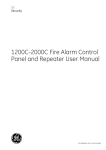
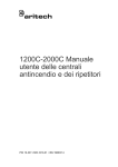
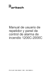
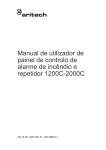
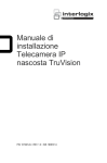
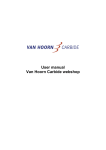
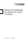
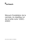
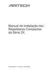
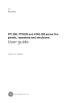
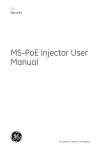
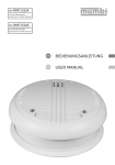
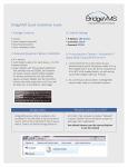
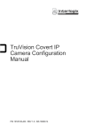
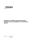
1200C-2000C Fire Alarm Control Panel and Repeater User Manual P/N 10-3311-505-1003-01 • ISS 18DEC14 Copyright Trademarks and patents © 2014 UTC Fire & Security. All rights reserved. The 1200C-2000C name and logo are trademarks of UTC Fire & Security. Other trade names used in this document may be trademarks or registered trademarks of the manufacturers or vendors of the respective products. Manufacture UTC CCS Manufacturing Polska Sp. Z o.o. Ul. Kolejowa 24. 39-100 Ropczyce, Poland Authorized EU manufacturing representative: UTC Fire & Security B.V. Kelvinstraat 7, 6003 DH Weert, Netherlands Certification 2012/19/EU (WEEE directive): Products marked with this symbol cannot be disposed of as unsorted municipal waste in the European Union. For proper recycling, return this product to your local supplier upon the purchase of equivalent new equipment, or dispose of it at designated collection points. For more information see: www.recyclethis.info. 2006/66/EC (battery directive): This product contains a battery that cannot be disposed of as unsorted municipal waste in the European Union. See the product documentation for specific battery information. The battery is marked with this symbol, which may include lettering to indicate cadmium (Cd), lead (Pb), or mercury (Hg). For proper recycling, return the battery to your supplier or to a designated collection point. For more information see: www.recyclethis.info. Contact information For contact information, see www. utcfssecurityproducts.eu. Content Important information ii Introduction ii Product compatibility ii Support ii Limitation of liability ii Controls and indicators 1 The control panel interface 1 User interface controls 2 General indicators 4 Controls buttons and indicators 6 Sounder buttons and indicators 7 Fire brigade buttons and indicators 8 Repeater buttons and indicators 9 Zone indicators 10 Operation 11 Panel operation in standby 11 Panel operation in fire alarm 12 Panel operation in pre-warning 13 Panel operation in fault 14 Maintenance 15 Fire alarm system maintenance 15 Battery maintenance 16 Product Compliance 17 1200C-2000C Fire Alarm Control Panel and Repeater User Manual i Important information Introduction This is the installation manual for UTC Fire & Security 1200C-2000C addressable fire alarm control panels and repeaters. Read these instructions and all related documentation entirely before operating this product. Product compatibility All models are compatible with UTC Fire & Security Aritech fire detectors and manual call points. Compatibility with third-party products cannot be guaranteed. Consult your local supplier for further information. Support For assistance operating and maintaining this product, contact your installation or maintenance contractor. Limitation of liability Installation in accordance with this manual, applicable codes, and the instructions of the authority having jurisdiction is mandatory. UTC Fire & Security shall not under any circumstances be liable for any incidental or consequential damages arising from loss of property or other damages or losses owing to the failure of UTC Fire & Security products beyond the cost of repair or replacement of any defective products. UTC Fire & Security reserves the right to make product improvements and change product specifications at any time. While every precaution has been taken during the preparation of this manual to ensure the accuracy of its contents, UTC Fire & Security assumes no responsibility for errors or omissions. ii 1200C-2000C Fire Alarm Control Panel and Repeater User Manual Controls and indicators This chapter describes the control panel interface, indicators, and controls. The control panel interface Figure 1: The control panel interface 1. 2. 3. 4. 5. LCD screen Alphanumeric keypad Fire brigade buttons and indicators Key switch Sounder buttons and indicators 6. 7. 8. 9. Repeater buttons and indicators Controls buttons and indicators Zone indicators General indicators 1200C-2000C Fire Alarm Control Panel and Repeater User Manual 1 User interface controls Key switch operation The key switch is used to restrict the operation of the fire panel controls. Table 1: Key switch enable/disable Position Status Description Disabled Panel operation is restricted. Enabled Panel operation is not restricted. The Silence Buzzer and Test buttons operate with the key switch in any position. User interface controls The user interface has 20 buttons, 10 of which are alphanumeric. The remaining 10 are described below. Table 2: Description of the control panel user interface controls Button Description Alpha selection (when using the alphanumeric buttons) Display the most recent alarm Print the current screen Scroll between Alarm, Fault and Conditions. View additional information when the "MORE" prompt appears on the LCD screen. Exit a menu Enter or confirm a value or selection Move to the next field on the LCD screen Move to the previous field on the LCD screen 2 1200C-2000C Fire Alarm Control Panel and Repeater User Manual Button Description Increase a value Decrease a value 1200C-2000C Fire Alarm Control Panel and Repeater User Manual 3 General indicators Figure 2: General indicators 1. 2. 3. 4. 5. 6. 7. Fire Alarm LEDs Fault LED Disable LED Supply fault LED System fault LED Processor running LED Supply On LED Table 3: Description of general indicators LED indicator Description Fire Alarm Two red LEDs indicate a fire alarm. Fault A yellow LED indicates one or more of the following general faults: 4 • Device fault· • Supply fault • Processor fault • Bell fault • Communications fault • Fire brigade fault· • Any test mode· • Any disablement 1200C-2000C Fire Alarm Control Panel and Repeater User Manual LED indicator Description Disable A yellow LED indicates that one or more of the following is disabled: Supply fault System fault • Devices on the loop • Area • Zone • Sounders • Fire brigade· • Any delays ON A yellow LED indicates one or more of the following supply faults: • A mains failure • A battery problem (battery disconnected or not charging) • An earth fault A yellow LED indicates one or more of the following: • Internal memory failure • Panel down • Clock failure • Global repeater down • Watchdog time out • Input fault • Tamper switch • Output fault • Service switch • Configuration fault • Logic error • Checksum fault • Memory lock • Protected memory overwritten • No checksums calculated • Time date wrong • Hardware test fault • Access fault • Fireman’s' panel down • FEP fault • Repeater down • Watchdog time-out Processor running A flashing green LED indicates normal operation Supply on A steady green LED indicates that the control panel is powered up 1200C-2000C Fire Alarm Control Panel and Repeater User Manual 5 Controls buttons and indicators Figure 3: Control buttons and indicators 1. 2. 3. 4. 5. Silence Buzzer Reset Disable Test Test Third Source (2000C control panels only) Note: Some features can only be accessed if the key switch is enabled (see “Key switch operation” on page 2). Table 4: Description of controls LED indicators LED indicator Key switch position Description Silence Buzzer Enabled or disabled The control panel internal buzzer activates for any new condition. The buzzer sound is: • • • Constant for a fire alarm Fast intermittent for a fault warning Slow intermittent for a condition warning Press the Silence Buzzer button to silence the buzzer. A steady yellow LED indicates that the buzzer has been silenced. Reset Enabled Press this button to reset the fire panel. Disable Enabled Press this button to display the Disable menu on the LCD screen. The yellow LED indicates a disablement. Test Enabled Press this button to display the Test menu on the LCD screen. The yellow LED indicates that a feature or device is being tested. Test Third Source Enabled or disabled Press this button to test the third source battery. The yellow LED is steady and the internal buzzer sounds intermittently. 6 1200C-2000C Fire Alarm Control Panel and Repeater User Manual Sounder buttons and indicators Figure 4: Sounder buttons and indicators 1. 2. 3. 4. Sound Delay ON/OFF Fault/Disable Silence Note: Some features can only be accessed if the key switch is enabled (see “Key switch operation” on page 2). Table 5: Description of sounders LED indicators LED indicator Key switch position Description Sound A red LED indicates that the sounders are activate (sounding). Delay ON/OFF A single LED indicates that the sounder delay has been toggled ON or OFF. Fault/Disable Enabled Press the Fault/Disable button to disable the sounders. The LED flashes when a fault is detected and is steady when the sounders are disabled. Silence Enabled A yellow LED indicates that the sounders have been silenced. Note: Functionality of the Sound and Silence buttons is defined by the control panel operating mode. 1200C-2000C Fire Alarm Control Panel and Repeater User Manual 7 Fire brigade buttons and indicators Figure 5: Fire brigade buttons and indicators 1. 2. 3. 4. Signal Delay ON/OFF Fault/Disable Stop fire brigade Note: Some features can only be accessed if the key switch is enabled (see “Key switch operation” on page 2). Table 6: Description of fire brigade LED indicators LED indicator Key switch position Description Signal Enabled Push this button to activate the fire brigade notification. A red LED indicates that a signal has been sent. Delay ON/OFF Fault/Disable The LED indicates that the fire brigade delay has been toggled ON or OFF. Enabled Stop Fire brigade Enabled Push this button to disable the fire brigade notification. The LED is steady when the feature is disabled and flashes when a fault is detected. Push this button to stop the fire brigade notification A yellow LED indicates that the signal has been stopped. Note: Functionality of the Signal and Stop Fire Brigade buttons is defined by the control panel operating mode. 8 1200C-2000C Fire Alarm Control Panel and Repeater User Manual Repeater buttons and indicators Figure 6: Repeater buttons and indicators 1. Panel 2. All Table 7: Description of repeater LED indicators LED indicator Key switch position Description Panel Enabled or disabled This indicator is used by global and local repeaters for panel emulation. The yellow LED indicates that a control panel is being emulated. Global repeater To start emulation: 1. Press the Panel button. 2. Enter the number of the panel to be emulated 3. Press the Enter button To stop emulation: 1. Press the Panel button. 2. Press "0". 3. Press the Enter button. When a global repeater is emulating a panel it is not necessary to stop emulation before emulating another panel. The global repeater will automatically stop the emulation before trying to emulate another panel. Local repeater: Press the Panel button to start emulating the panel. Emulation will stop when the button is pressed again. All Enabled or disabled Press this button for the global repeater panel to send a command to all control panels that the global repeater communicates with. The command from the next command button to be pressed is then sent to all corresponding panels. 1200C-2000C Fire Alarm Control Panel and Repeater User Manual 9 Zone indicators Each zone has two LED indicators. A red LED indicates a fire alarm and a yellow LED indicates a fault. The zone fault LED flashes when there is a fault and remains steady if the entire zone has been disabled. Figure 7: Zone fire and fault indicators 10 1200C-2000C Fire Alarm Control Panel and Repeater User Manual Operation Panel operation in standby Normal operation (standby) is indicated as shown below. Table 8: Normal operation LED indicator Status Supply ON The green LED is steady Processor running The green LED is flashing Sounder indicators: Delay ON or Delay OFF The yellow Delay ON LED is steady when a delay is running. This is logged as a condition. Press the SILENCE BUZZER button to silence the internal buzzer. Fire brigade indicators: Delay ON or Delay OFF The yellow Delay ON LED is steady when a delay is running. This is logged as a condition. Press the SILENCE BUZZER button to silence the internal buzzer. All other LEDs OFF Figure 8: System Status menu (normal operation) SYSTEM STATUS 09:17:37 (Site text – up to 40 characters) Fri 12/10/04 (Site text – up to 40 characters) Scanning Day Mode Zones on Alarm: 0 Faults: 0 Cond.: 0 E P: 1 SDZ 1. Menu title, date, and time 2. Site text (up to 40 characters) 3. Operations status line (operations are displayed in full here) 4. User keys (none shown in this screen) 5. System status. The current number of fire alarms, faults, and conditions are displayed here as well as repeater information (P is global with panel number shown, L is local) and a summary of the operations (eg, SDZ). 1200C-2000C Fire Alarm Control Panel and Repeater User Manual 11 Panel operation in fire alarm The Fire Alarm LEDs are lit and the internal buzzer sounds constantly to indicate a fire alarm. Sounders are also activated. Figure 9: System Status menu screen in normal operation ALARM: 1 Event: 79 Zone: 6 Area: 1 ALMLVL Address: 1/12 Fire MCP 06/02/05 09:39:34 Active (Site text – up to 40 characters) X Alarm: 1 Faults: 0 Cond.: 0 P: 1 SDZ 1. Look at the screen to see where the fire is located. In the example above, the fire is in zone 6, area 1 at address 12 in loop 1. 2. Press Display alarm to view the most recent alarm. 3. If more than one fire alarm exists, use the up and down arrows to view each alarm. 4. Press Silence Buzzer to silence the internal buzzer and to acknowledge the alarm. 5. Once the evacuation of the building is complete, silence the sounders by turning the enable/disable key switch to enable (see “Key switch” on page 2). 6. Press the Silence button. The yellow Silence LED is steady. 7. If you need to restart the evacuation, press the Sound button. 8. When the fire situation is under control, the fire panel may be returned to normal condition by turning the enable/disable key switch to enable. 9. Press the Reset button. If the fire alarm continues, then one of the following is true: • The fire is not under control (perform the above checks again). • The cover glass of a manual call point is broken (repair or disable the manual call point). 12 1200C-2000C Fire Alarm Control Panel and Repeater User Manual Panel operation in pre-warning The internal buzzer sounds with a short intermittent tone to indicate a prewarning. Figure 10: The alarm screen (pre-warning) ALARM: 1 Event: 79 Zone: 6 Area: 1 ALMLVL Address: 1/12 Pre-Warning MCP 06/02/05 09:39:34 Active (Site text – up to 40 characters) X Alarm: 0 Faults: 0 Cond.: 0 P: 1 SDZ 1. Look at the screen to see the location of the detector in pre-warning. In the example shown above, the pre-alarm is in zone 6, area 1 at address 12 in loop 1. 2. If more than one pre-warning exists, use the up and down arrows to view each pre-warning condition. 3. Press Silence Buzzer to silence the internal buzzer and to acknowledge the pre-warning. 4. Investigate the cause of the pre-warning condition. 5. When the pre-warning condition is under control, turn the enable/disable key switch to enable to return the fire panel to normal condition. 6. Press the Reset button. If the pre-warning continues, then one of the following is true: • • The event is not under control (return step 3 above). The detectors are contaminated with smoke (clean the detectors). 1200C-2000C Fire Alarm Control Panel and Repeater User Manual 13 Panel operation in fault The internal buzzer sounds to indicate a fault. 1. Press the Silence Buzzer button to silence the internal buzzer. 2. The yellow Fault LED is steady to indicate a fault in the fire system. 3. The yellow fault LED for the corresponding feature or device is also steady. Table 9: Fault LED indications LED indication Action required A specific zone Call the maintenance engineer. Disable A zone, loop, or device has been disabled. Supply fault Check the mains supply and battery. System fault Call the maintenance engineer. Test (Controls) A specific zone has been placed in test mode. The fault remains until the test is complete. Fault/Disable (Sounders) The sounders are disabled or there is a fault with the connection. Enable the sounders. If the fault continues, check the connections. Fault/Disable (Fire brigade) The fire brigade notification has been disabled or there is a fault with the connection, Enable the Fire brigade notification. If the fault continues, check the connections. Fault details are also displayed on the LCD screen. The figure below shows a communication fault in zone 6, area 1 at address 12 in loop 1 (the fault is in a specific zone). Figure 11: The alarm screen (fault) ALARM: 1 Event: 79 Zone: 6 Area: 1 ALMLVL Address: 1/12 Communication fault MCP 06/02/05 09:39:34 Active (Site text – up to 40 characters) X Alarm: 0 14 Faults: 1 Cond.: 0 P: 1 SDZ 1200C-2000C Fire Alarm Control Panel and Repeater User Manual Maintenance This section provides information to help you maintain your UTC Fire & Security product. Caution: This product must be installed and maintained by qualified personnel adhering to all applicable standards and local authority laws. Fire alarm system maintenance Your fire alarm system must be regularly tested and serviced in order to ensure its reliable operation. The following maintenance routine is recommended: Daily • • Check that the panel indicates normal operation. If it does not, check that any fault indicated is recorded in the log book and reported to the maintenance personnel. Check that any fault warning recorded the previous day has received attention. Quarterly • • • • Check the log book entries and ensure that any necessary action has been taken. Check the state of the batteries and corresponding connections. Visually inspect the control panel for signs of moisture and other deterioration. Test the alarm, fault, and ancillary functions of the fire panel. Yearly • • • • • Carry out the recommended daily and quarterly inspection and test routines. Check each detector for correct operation in accordance with the manufacturer's recommendations. Visually inspect all cable fittings and equipment to ensure that no damage has taken place. Visually inspect all electrical connections to make sure that they are securely fastened, that they have not been damaged and that they are appropriately protected. Visually inspect the manual call points, detectors, and sounders to ensure that no structural or occupancy changes have affected their location requirements. 1200C-2000C Fire Alarm Control Panel and Repeater User Manual 15 Battery maintenance Batteries must be replaced periodically as recommended by the manufacturer. The useful life of the battery is approximately 4 years. Avoid the total discharge of the batteries. Battery test fail When the control panel indicates that the battery test has failed, check the following: • That the battery leads are in good condition • That the battery leads are connected securely and correctly at the battery and at the panel • That the control panel event log does not indicate a mains failure in the last twenty-four hours If the leads are in good condition, all connections are correct, and the control panel continues to report that the test has failed twenty-four hours after the last mains failure, then the batteries should be replaced immediately. Replacing batteries To replace the batteries: 1. Disconnect and remove the existing batteries from the cabinet. 2. Install and connect the replacement batteries using the bridge provided. Observe correct polarity. Always use the recommended replacement batteries. Dispose of used batteries according the European regulations and/or instructions from local authorities. 16 1200C-2000C Fire Alarm Control Panel and Repeater User Manual Product Compliance All 1200C-2000C control panels are designed to comply with the requirements of European standards EN 54-2 for control and indicating equipment, and EN 54-4 for power supply equipment). EN 54-2 compliance for control panels with the SD2000 module Control panels with the SD2000 module installed have the following options with requirements according to EN 54-2: Table 10: EN 54-2 options with requirements with the SD2000 module Clause Description 7.8 Output to fire alarm devices 7.9 Output to fire routing equipment 7.10 Output to fire protection equipment 7.11 Delay to output 7.12 Dependency on more than one alarm signal 7.13 Alarm counter 8.4 Total loss of the power supply 9.5 Disablement of addressable points 10 Test EN 54-2 compliance for control panels with the VDS2000 module Control panels with the VDS2000 module installed have the following options with requirements according to EN 54-2: Table 11: EN 54-2 options with requirements with the VDS2000 module Clause Description 7.8 Output to fire alarm devices 7.9 Output to fire routing equipment (+ VDE0833) 7.10 Output to fire protection equipment (+ VdS requirements) 7.11 Delay to output 7.12 Dependency on more than one alarm signal (+ VDE0833) 7.13 Alarm counter 8.4 Total loss of the power supply 8.9 Output to fault routing equipment 9.5 Disablement of addressable points 10 Test 1200C-2000C Fire Alarm Control Panel and Repeater User Manual 17 Control panels with the VDS2000 module also allow for: • • • • • Interface to FBF Interface to FAT interface to FSK interface to Hauptmelder interface to EMZ European regulations for construction products This section includes both regulatory information and a summary on the declared performance according to the Construction Products Regulation 305/2011. For detailed information refer to the product Declaration of Performance (DoP). Table 12: Certification Certification body 1134 Manufacturer UTC CCS Manufacturing Polska Sp. Z o.o. Ul. Kolejowa 24. 39-100 Ropczyce, Poland Authorized EU manufacturing representative: UTC Fire & Security B.V., Kelvinstraat 7,6003 DH Weert, The Netherlands Year of first CE marking 09 Declaration of Performance number 360-3315-0299 EN 54 EN 54-2:1997+A1:2006 EN 54-4:1997+A1:2002+A2:2006 Product identification See model number on product identification label Intended use See DoP point 3 Essential characteristics See DoP point 9 18 1200C-2000C Fire Alarm Control Panel and Repeater User Manual