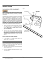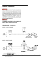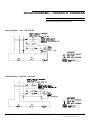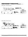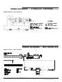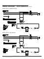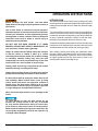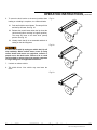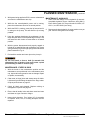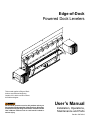
1
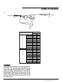
Edge-of-Dock Powered Dock Levelers This manual applies to Edge-of-Dock levelers manufactured beginning October 2011 with the serial numbers 6103000 and higher. Do not install, operate or service this product unless you have read and understand the Safety Practices, Warnings, Installation and Operating Instructions contained in this User’s Manual. Failure to do so could result in death or serious injury. User’s Manual Installation, Operations, Maintenance and Parts Part No. 6007632G table of contents Table of Contents........................................................2 Introduction..................................................................2 Safety Signal Words....................................................2 Safety Practices..........................................................3 Owner's Responsibilities.............................................4 Ramp Lip Grades........................................................5 Installation...................................................................6 Wiring Diagrams — Standard.................................... 14 Wiring Diagrams — with Interlock............................. 16 Operating Instructions...............................................19 Planned Maintenance................................................22 Hydraulic Troubleshooting.........................................26 Parts List...................................................................28 Warranty — Air EOD.................................................46 Warranty — Hydraulic EOD.......................................47 introduction Welcome and thank you for choosing this dock leveler. This User’s Manual contains information that you need to safely install, operate and maintain the dock leveler. It also contains a complete parts list and information about ordering replacement parts. Please keep and read this User’s Manual before using your new dock leveler. safety signal words You may find safety signal words such as DANGER, WARNING, or CAUTION throughout this User’s Manual. Their use is explained below: This is the safety alert symbol. It is used to alert you to potential personal injury hazards. Obey all safety messages that follow this symbol to avoid possible death or injury. Indicates an imminently hazardous situation which, if not avoided, will result in death or serious injury. Indicates a potentially hazardous situation which, if not avoided may result in minor or moderate injury. Indicates a potentially hazardous situation which, if not avoided, could result in death or serious injury. Notice is used to address practices not related to personal injury. 2 ©2011 4Front Engineered Solutions, Inc. 6007632G — Powered Edge-of-Dock Levelers December 2011 safety practices Read these safety practices before installing, operating or servicing the dock leveler. Failure to follow the safety practices could result in death or serious injury. If you do not understand the instructions, ask your supervisor to explain them to you or contact your local distributor. Before doing any maintenance or repair on the dock leveler SECURE WITH THE MAINTENANCE STRUT. See Fig. 25 and instructions on pages 22-23. operation Do not use this unit to service trailers outside its intended working range, which is 3" above and 3" below dock. Verify with the manufacturers of all equipment to be used on your specific edge-of-dock leveler, to ensure that operating equipment at all specified grades are within safe operation. Do not operate any equipment that will not safely operate at any of the grades shown on page 5 at either ramp or lip. Use of dock leveler is restricted to trained operators. Follow procedures on placards posted near dock leveler. Call 972-466-0707 or 800-525-2010 for replacement placards, warning labels or owner’s manual. Never exceed the rated capacity of the dock leveler. Do not operate the dock leveler with equipment, material or people on the ramp or lip. Do not operate the dock leveler when anyone is in front of it unless they are securing the MAINTENANCE STRUT. Stay clear of the dock leveler when it is moving. Never exceed 5 mph when driving on leveler. Never travel on leveler unless lip is securely on vehicle floor. Never travel on leveler while in rest position. Never travel on the bumper blocks or over the edges of the leveler. Do not use the dock leveler if it looks broken or does not seem to work right. Tell your supervisor it needs repair right away. Visually check that lip is supported by the vehicle bed before driving on ramp. December 2011 Chock vehicle wheels or lock vehicle in place with a vehicle restraining device, and set brakes before loading or unloading. Do not stand in the driveway between the dock leveler and a backing vehicle. Move all equipment, material or people off dock leveler, and store dock leveler at dock level before allowing the vehicle to move away from the dock. Do not use a fork truck or other material handling equipment to lift or lower the ramp. Do not attempt to lift the dock leveler ramp or lip by any means other than that described in the operating procedures contained in this manual. If the dock leveler does not operate correctly when using the operating procedures contained in this manual, DO NOT USE THE DOCK LEVELER. Contact your local distributor for maintenance and service repair. Before chocking wheels or engaging vehicle restraint, dump air from air ride suspensions and set parking brakes. Keep feet clear of the underside of ramp and lip when raising and lowering dock leveler. Installation, Maintenance And seRVICe Place barricades on the dock floor around the dock leveler final location and in the driveway in front of the dock leveler final location while installing, maintaining or repairing the dock leveler. Do not raise the ramp plate and lip plate or install the maintenance strut with the over center return spring system attached to the deck and back plate. Always disable the system by removing the over center spring bracket pivot pin (item 14 shown on page 29) prior to raising the dock leveler. Do not operate the dock leveler when anyone is in front of it unless they are positioning the MAINTENANCE STRUT. PUT THE MAINTENANCE STRUT IN PLACE before doing any maintenance or repair under the dock leveler. See Fig. 25 and instructions on pages 22-23. When working on a powered EOD, after raising, disconnect the power and properly tag or lock out before doing any maintenance or repair under the dock leveler. 6007632G — Powered Edge-of-Dock Levelers ©2011 4Front Engineered Solutions, Inc. 3 safety practices, continued All electrical troubleshooting or repair must be done by a qualified technician and must meet applicable codes. Disconnect the power and properly tag or lock out before doing any electrical work. If it is necessary to make troubleshooting checks inside the control box with the power on, USE EXTREME CAUTION! Do not place fingers or uninsulated tools inside the control box. Touching wires or other parts inside the control box could result in electrical shock, death, or serious injury. oWneR’s ResPonsIBILItIes The owner’s responsibilities include the following: The owner should recognize the inherent danger of the interface between dock and transport vehicle. The owner should, therefore, train and instruct operators in the safe use of dock leveling devices. When a transport vehicle is positioned as closely as practical to a dock leveling device, there shall be at least 4" of overlap between the front edge of the lip and the edge of the floor or sill of the transport vehicle. Nameplates, cautions, instructions and posted warnings shall not be obscured from the view of operating or maintenance personnel for whom such warnings are intended. Warnings which are worn or non-legible should be replaced. Manufacturer’s recommended periodic maintenance and inspection procedures in effect at date of shipment shall be followed, and written records of the performance of these procedures should be kept. The owner shall see that all nameplates and caution and instruction markings or labels are in place and that the appropriate operating and maintenance manuals are provided to users. Modifications or alterations of dock leveling devices shall be made only with written permission of the original manufacturer. When industrial vehicles are driven on and off transport vehicles during the loading and unloading operation, the brakes on the transport vehicle shall be applied and wheel chocks or positive restraints that provide the equivalent protection of wheel chocks engaged. The dock leveler should never be used outside its vertical working range or vertical lifting range or outside the manufacturer’s labeled rated capacity. It must also be compatible with the loading equipment and other conditions relating to the dock. Dock leveling devices that are structurally damaged or have experienced a sudden loss of support while under load, such as might occur when a transport vehicle is pulled out from under the dock leveling device, shall be removed from service, inspected by the manufacturer’s authorized representative, and repaired as needed before being placed back in service. 4 ©2011 4Front Engineered Solutions, Inc. 6007632G — Powered Edge-of-Dock Levelers December 2011 ramp lip grades Fig. 1 Lip grade Ramp grade VEHICLE BED POSITION (in) A B O V E D O C K B E L O W D O C K 5.0 4.5 4.0 EOD GRADE (%) RAMP LIP 27.9 -1.5 25.2 -1.6 22.5 -1.6 3.5 3.0 2.5 19.8 17.2 14.5 -1.7 -1.7 -1.7 2.0 1.5 1.0 0.5 0.0 0.5 1.0 1.5 2.0 11.8 9.2 7.6 6.5 5.4 4.3 3.2 2.1 0.9 -1.7 -1.7 -2.4 -3.5 -4.6 -5.7 -6.8 -7.9 -9.1 2.5 3.0 3.5 -0.2 -1.3 -2.4 -10.2 -11.3 -12.4 4.0 4.5 5.0 -3.5 -4.6 -5.7 -13.5 -14.6 -15.7 Verify with the manufacturers of all equipment to be used on your specific edge-of-dock leveler, to ensure that operating equipment at all specified grades are within safe operation. Do not operate any equipment that will not safely operate at any of the above stated grades at either ramp or lip. Failure to follow this warning could result in death or serious injury. December 2011 6007632G — Powered Edge-of-Dock Levelers ©2011 4Front Engineered Solutions, Inc. 5 installation DoCK MountInG steeL RequIReMents Before installing the dock leveler, read and follow Safety Practices on page 3. Place barricades around pit on dock floor and drive while installing, maintaining or repairing dock leveler. All anchor bolts used must be installed in accordance with the manufacturer’s instructions. Do not install anchor bolts in cracks or expansion joints in concrete. Installation in cracks or expansion joints may cause the anchors to come loose and pull out. All anchor bolt lengths must suit local codes and conditions. Type and depth of concrete will determine type and length of anchor bolts required. Use of improperly installed anchor bolts could result in death or serious injury. Fig. 2 Curb channel Dock (concrete) 1. The face of the dock must be equipped with a minimum of 8" channel with 1/4" x 1" x 10" anchor straps on 10" centers. Mounting on curb angle alone is NOT recommended. 2. There are four main mounting methods: installation with curb channel, transition plate, face plate and with transition plate, and formed angle. Follow the section that addresses your installation and then continue to the GENERAL INSTALLATION section on page 10 of this manual. Weld Dock leveler base plate Dock leveler shown for reference only Curb channel (Isometric view) InstALLAtIon WItH CuRB CHAnneL 1. If curb channel is not already present, position it as shown in Fig. 2. Pour concrete. NOTE: Concrete preparation should provide adequate depth and width to accommodate the channel with sound concrete foundation. Tie in rebar with anchor straps. Check local building codes for further information. 2. Ensure all concrete is thoroughly cured before installation and use of dock leveler. 3. Proceed to GENERAL INSTALLATION section on page 10 of this manual. 6 ©2011 4Front Engineered Solutions, Inc. 6007632G — Powered Edge-of-Dock Levelers December 2011 installation, continued InstALLAtIon WItH tRAnsItIon PLAte NOTE: A transition plate is required whenever the curb channel is less than the 8" recommended by 4Front Engineered Solutions, Inc., or whenever the edge of dock is to be mounted above dock level. Fig. 3 Beveled transition plate Weld Dock leveler mounting plate 1. Lay the transition plate on top of dock. 2. If using a beveled transition plate, position transition plate flush with the front of dock edge and skip to step 6. See Fig. 3. 3. If using a kinked transition plate, position transition plate flush with the front of dock edge and mark the location of the back of the transition plate on floor of dock. See Fig. 4. Dock (concrete) Dock leveler shown for reference only 4. Slide transition plate forward 2” and mark location of the back of the transition plate on floor of dock. 5. Remove transition plate and cut a groove in the concrete 1/2" deep between lines marked in steps 3 and 4. Position plate flush with the front of the dock edge. 6. Tack weld transition plate to curb angle nosing in at least four places. 7. Install 5/8" dia x 5" long (supplied by others) wedge anchor bolts in the transition plate. When bolts are tight in the concrete. Torque to manufacturer’s specification. Tack in place. Remove nuts, cut bolts flush with top of transition plate and plug weld bolts to plate. Fig. 4 Kinked transition plate Weld Dock leveler mounting plate All anchor bolts must be installed in accordance with the manufacturer’s instructions. Improper installation could result in death or serious injury. Do not install anchor bolts in cracks or expansion joints in concrete. Installation in cracks or expansion joints may cause the anchors to come loose and pull out. Use of improperly installed anchor bolts could result in death or serious injury. Dock (concrete) Dock leveler shown for reference only NOTE: All anchor bolt lengths must meet local codes and conditions. Type and depth of concrete will determine type and length of anchor bolts required. 8. Proceed to GENERAL INSTALLATION section on page 10 of this manual. December 2011 6007632G — Powered Edge-of-Dock Levelers ©2011 4Front Engineered Solutions, Inc. 7 installation, continued InstALLAtIon WItH FACe PLAte with tRAnsItIon PLAte For installations above dock floor height (up to 3" max) the transition plates listed in Fig. 5 must be used. Fig. 5 Plate LengthApplicationPart Number 12” (1-1/2” or less above dock) 6007621 18” (1-1/2” to 2-1/4” above dock) 6007623 24” (1-1/2” to 3” above dock) 6007625 1. Position the face plate at desired height above dock level (0" minimum to 3" maximum). See Fig. 6. 2. Continuously weld the face plate to the mounting surface with a 1/4" fillet in accordance with AWS Standards. See Fig. 6. 3. Position transition plate flush with the top edge of the face plate. Mark along back edge of transition plate on top of dock. Fig. 6 Transition plate (See Fig. 5) Weld Dock leveler base plate 4. Move the transition plate 2" forward. Mark another line along the back edge of transition plate on top of dock. 5. Remove the transition plate and cut a groove in the concrete 2" wide x 1/2" deep between the lines marked in steps 3 and 4. 6. While supporting the transition plate against the top back edge of the face plate. Measure and place full length structural angle (supplied by others) as shown. Weld to back of face plate. 7. Locate and weld full length schedule 40 pipe (supplied by others) to bottom of transition plate as required. 8. Install 5/8" x 5" wedge anchor bolts (supplied by others) with the transition plate. See part numbers and transition plate sizes listed in Fig. 5 above. Torque to manufacturer’s specification. Remove nuts, cut bolts flush with top of transition plate and plug weld bolts to plate. Curb angle Dock (concrete) Face plate Dock leveler shown for reference only Weld a full width piece of structural angle here (weld to leveler first) to align leveler and provide a purchase for edge of transition plate. 9. Continuously weld the transition plate to the face plate with a 1/4" fillet in accordance with AWS Standards. See Fig. 6. 10. Proceed to GENERAL INSTALLATION section on page 10 of this manual. 8 ©2011 4Front Engineered Solutions, Inc. 6007632G — Powered Edge-of-Dock Levelers December 2011 installation, continued installation with formed angle 1. Lay formed angle on top of dock. 2. If there is no curb angle, some concrete on edge-of-dock may need to be removed to allow angle to lie flush against wall. See Fig. 7. Fig. 7 Formed angle Remove concrete as required (2" max in each direction). Fill in with concrete as required. Dock leveler base plate 3. If there is curb angle present, the lower portion of formed angle will need to be spaced out to allow angle to lie flush against wall. See Fig. 8. 4. Position formed angle in desired position on dock edge and mark location of back of angle on floor of dock. 5. Slide formed angle forward 2" and mark location of back of angle on floor of dock. Dock (concrete) Dock leveler shown for reference only 6. Remove angle and cut a 2" wide x 1/2" deep groove in the concrete between two lines marked in steps 4 and 5. 7. Place formed angle on dock, making sure back edge of leg on top of dock is recessed in groove and both legs are tight against top and face of dock. Increase depth or width of groove as required. Fig. 8 Formed angle 8. Install 5/8" x 5" wedge anchor bolts (supplied by others) on top and front faces on 10" centers. All anchor positions must be used. Torque to manufacturer’s specification. Remove nuts from bolts on top of dock. Cut bolts flush with top of angle and plug weld bolts to formed angle. Weld nuts to bolts and angle on face of dock. NOTE: For air powered units 5" x 1/2” dia. mushroom head spike anchors to be used on front face in locations directly behind air pan assembly. 9. Position the dock leveler base plate 1/4" below top of formed angle. 10. Proceed to GENERAL INSTALLATION section on page 10 of this manual. December 2011 Curb angle Weld Dock leveler base plate Dock leveler shown for reference only Dock (concrete) Shim as required for rigid support 6007632G — Powered Edge-of-Dock Levelers ©2011 4Front Engineered Solutions, Inc. 9 installation, continued General installation Read and follow Safety Practices on page 3. Failure to follow these safety practices could result in death or serious injury. Installation should not be attempted by persons not familiar with equipment and techniques required for proper installation. Improper installation could result in death or serious injury. 1. Using a 1,000 lbs. minimum capacity load centering eye bolt, secure the lip plate using the lifting hole. at the center of the width. See Fig. 9. Inadequate lifting equipment or practices can cause a load to fall unexpectedly. Make sure the lifting chain or other lifting devices are in good condition and have a rated capacity of at least 1000 lbs. for the lifting angle used. Never allow anyone to stand on or near the dock leveler when it is lifted or placed onto the dock. Stand clear of the dock leveler when it is being placed onto the dock. Failure to follow this warning can allow the dock leveler to fall, tip, or swing into people, resulting in death or serious injury. The leveler is shipped with the over center spring disconnected. Follow installation instructions regarding assembly only at the correct step. 3. Weld two 1/4" x 2" welds at the upper outside edges of the mounting plate and plug weld the two outer holes in the mounting plate if curb channel is not used. Install one 5/8" x 5" wedge anchor in each of the outer holes. Torque to manufacturer’s specification. 4. Using the load centering eye bolt, lower the ramp plate and lip plate to the stored position. While lowering the dock leveler to the rest position, it is necessary to have another person use a pipe or similar device to hold the lip extender link disengaged. This person needs to stand clear of the leveler while it is being lowered. Disengaging the lip link will prevent the lip from extending out away from the dock. 5. As the ramp plate and lip plate descend, watch for smooth operation of the ramp plate and lip plate hinges. Do not allow lip and ramp to fall free. Allowing the dock leveler to fall free could result in the dock leveler coming free from the dock or damaging linkage, resulting in death or serious injury. Do not allow lip to extend out away from the dock before all welding and anchor installation is complete. Operating the dock leveler before all installation is complete could result in death or serious injury. Fig. 9 Lip The maintenance strut must always be installed into the maintenance strut cup mounted to the back plate whenever the return spring is unattached, the lip plate is in the up position, and lip plate is not supported by the lifting chain. Failure to follow this warning can allow the dock leveler to fall resulting in death or serious injury. Lifting hook Ramp Lifting hole Maintenance strut 2. Position dock leveler mounting plate centered on face of dock and 1/4" below top of curb channel, transition plate or formed angle plate. See Fig. 6. The dock leveler must be plumb to dock face to operate properly. Use shims or remove concrete as necessary to make the mounting plate plumb. Anchor holes (as required) 1/4 MTG clip 10 ©2011 4Front Engineered Solutions, Inc. 6007632G — Powered Edge-of-Dock Levelers Air pan assembly (air powered only) Base plate December 2011 installation, continued Use care when welding. Do not allow weld or weld splatter on the hinge tubes. Weld on the hinge tubes may interfere with normal operation of the dock leveler. 13. Add 3" x 3" x 1/4" angle clips and anchors as required to stabilize bumper. See Fig. 10. Fig. 10 1/4 6. Ensure the base plate is plumb and flush with the dock wall. Tack weld behind each base plate tube. Finish weld as shown in Fig. 15 using minimum 1/4" welds. Weld typical on face plate tubes. 7. Using the load centering eye bolt and a lifting device, raise the ramp plate and lip plate to the full upright position, checking for binding of the ramp and mounting plate hinge. Do not allow lip and ramp to fall free. Allowing the dock leveler to fall free could result in the dock leveler coming free from the dock or damaging linkage, resulting in death or serious injury. Do not allow lip to extend out away from the dock before all welding and anchor installation is complete. Operating the dock leveler before all installation is complete could result in death or serious injury. 8. Install the maintenance strut into the maintenance strut cup. On installations with curb channel, plug weld all remaining anchor holes in mounting plate to curb channel. On air EOD without curb channel make sure to drill holes for 1/2" Dia. X 5" long mushroom head spike anchors in remaining holes. Install spike anchors. On hydraulic EOD without curb channel drill holes for 5/8" x 5" long wedge anchors in remaining holes. Install and torque anchors to manufacturer’s specification. 9. Position the bumper blocks aligned with the top edge of the dock (or top edge of transition plate if used) with the flange facing away from the leveler. Butt the flat side along the edge of the base plate. Tack in place. 10. Check for square alignment. Correct any misalignment. 11. Weld bumper with a continuous 1/4" minimum bead across the top and adjacent to the leveler in accordance with AWS standards. 1/4 As required As required 1/4 As required All anchor bolts must be installed in accordance with the manufacturer's instructions. Improper installation could result in death or serious injury. Do not install anchor bolts in cracks or expansion joints in concrete. Installation in cracks or expansion joints may cause the anchors to come loose and pull out. Use of improperly installed anchor bolts could result in death or serious injury. All anchor bolt lengths must suit local codes and conditions. Type and depth of concrete will determine type and length of anchor bolts required. 14. Clean away all debris and paint all welded joints. Fig. 11 Upper and lower flange must have 1/4" thick X 1" wide X 8" long strap anchors alternating every 10" with outboard straps on top flange 3" 12" 8" min. 24" 25" 4" 12. Anchor bumpers with 5/8" x 5" long wedge anchors in holes provided. Torque to manufacturer’s specification. See page 13 for wedge anchor installation instructions. Dock face Pit mounted EOD December 2011 Dock floor 6007632G — Powered Edge-of-Dock Levelers ©2011 4Front Engineered Solutions, Inc. 11 installation, continued 15. Mount and wire incoming power from the fused disconnect to the pushbutton control box and wire from the control box to the junction box. See Fig. 1113. Follow all applicable codes and standards. Size of conduit and wire gauge may vary with local electrical codes. See the correct wiring diagram for your voltage and phase located on pages 14-18. Always make sure the incoming power agrees with the voltage and phase on the motor. Fig. 12 Push-button Control Box 48" Dock face mounted AEOD 26" NOTE: For hydraulic EODs skip to step 16. 16. Lift the air bag pan assembly on to the hooks of the back plate as shown in Fig. 9. The air bag will be positioned against the dock face and the air bag clamp bar will be visible from the top. 38" 54" 17. Wire from the hydraulic or air motor to the junction box. See Fig. 12 and 13. On single phase air leveler installations if the power cord is to be hard wired into the junction box, cut the cord immediately behind the plug. This will allow for the maximum length of cord between the power cord bushing and the junction box. The power cord may be looped together and stabilized with plastic cable ties (provided by others). Keep the cable a minimum of 2" from all moving parts and secure safely underneath the air bag pan fan assembly as illustrated in Fig. 12. Fig. 13 Push-button Control Box 48" Dock face mounted HEOD 12" 18. Temporarily remove the over center spring bracket pivot pin. See Fig. 14. With the spring attached to the over center spring bracket hang the spring form the spring roller located on the deck. Orient spring with the opening in the spring loop facing driveway. See Fig. 14. 19. Remove the maintenance strut and use the load centering eye bolt and lifting device to carefully lower the dock leveler to the rest position, with the lip pendant. 20. Re-install the 5/8" pivot pin through the over center spring bracket pivot pin and base plate and secure with washer and cotter pin. See Fig. 14. 30" 54" Fig. 14 21. Permanently mount the laminated dock leveler WARNING and OPERATION PLACARD on the wall within 4 inches of the dock leveler control. 22. Operate the dock leveler four times through the complete cycle to check operation. Refer to the OPERATION section for the proper operation procedure. 12 ©2011 4Front Engineered Solutions, Inc. Over center spring bracket pivot pin 6007632G — Powered Edge-of-Dock Levelers Spring roller December 2011 installation, continued Fig. 15 8" 4" 4" 4" 4" 8" Use anchor bolts when installed on curb angle Plug weld anchor holes when mounting on embed channels (six places) Wedge anchor installation (USE WITH CURB ANGLE AND TRANSITION PLATE ONLY) — Hydraulic models only Fig. 16 When anchors are used with curb angle for mounting, a transition plate must also be used. See page 7. Do not install the vehicle restraint anchor bolts into aged or unsound concrete. Use 5/8" x 5" long wedge anchors on smooth 4,000 psi concrete walls only. For aggregate, cinder block or tilt walls - consult factory. Oversized holes in the base material will make it difficult to set the anchor and will reduce the anchor’s load capacity. Do not use an impact wrench to set or tighten the wedge anchors. Drill a hole in the concrete using a carbide drill bit the same diameter as the nominal diameter of the anchor to be installed. Drill the hole to the specified embedment depth and blow it clean using compressed air. Alternatively, drill the hole deep enough to accommodate embedment depth and dust from drilling. Assemble the anchor with nut and washer so the top of the nut is flush with the top of the anchor. Place the anchor in the fixture and drive into the hole until washer and nut are tight against fixture. Torque to manufacturer’s specification. See Fig. 16. December 2011 6007632G — Powered Edge-of-Dock Levelers ©2011 4Front Engineered Solutions, Inc. 13 wiring diagrams Before doing any electrical work, make certain the power is disconnected and properly tagged or locked off. All electrical work must be done by a qualified technician and meet all applicable codes. If it is necessary to make troubleshooting checks inside the control box with the power on, USE EXTREME CAUTION. Do not place your fingers or uninsulated tools inside the control box. Touching wires or other parts inside the control box could result in electrical shock, death or serious injury. Air powered EOD models only: Never allow more than 130 volts to be connected to the 115 volt motor circuit. Damage to motor, pushbutton, air bag, and death or serious injury may result. Wiring diagrams — standard air 908-753 — 120V, 1 PH, 50/60 Hz Control station Circuit Breaker (By Others) 20 AMP MAX 120V 1 Phase 50/60 Hz BLK Line GRN Grn Neutral Motor WHT Pit wall receptacle NEMA 5-15R (by others) 1 Phase 120V 50/60 Hz V 909-075 — 220V, 1 PH, 60 Hz 14 ©2011 4Front Engineered Solutions, Inc. 6007632G — Powered Edge-of-Dock Levelers December 2011 Wiring diagrams — HYDRAULIC, standard NOTE: For 24V incoming power consult factory. 6006461, 6006420 — 120V, 1 PH, 50/60 Hz 6006462, 6006421 — 208-240V, 1 PH, 60 Hz December 2011 6007632G — Powered Edge-of-Dock Levelers ©2011 4Front Engineered Solutions, Inc. 15 Wiring diagrams — HYDRAULIC, standard, continued 6006450, 6006423 — 208-230V, 3PH, 50/60 Hz 6006451, 6006425 — 460-480V, 3PH, 60 Hz 16 ©2011 4Front Engineered Solutions, Inc. 6007632G — Powered Edge-of-Dock Levelers December 2011 Wiring diagrams — HYDRAULIC, standard, continued 6006452, 6006426 — 575V, 3PH, 60 Hz Wiring diagrams — with interlock 6011372, 6011971 — 120V, 1ph, 60 hz December 2011 6007632G — Powered Edge-of-Dock Levelers ©2011 4Front Engineered Solutions, Inc. 17 Wiring diagrams — with interlock, continued 6011524, 6011972 — 208/230V, 1PH, 60 Hz 18 ©2011 4Front Engineered Solutions, Inc. 6007632G — Powered Edge-of-Dock Levelers December 2011 Wiring diagrams — with interlock, continued 6011325, 6011968 — 208V, 3PH, 60 hz 6011761, 6011969 — 240V, 3PH, 60 HZ December 2011 6007632G — Powered Edge-of-Dock Levelers ©2011 4Front Engineered Solutions, Inc. 19 Wiring diagrams — with interlock, continued 6011326, 6011970 — 460-480V, 3ph, 60 hz 6011651, 6011973 — 575V, 3PH, 60 Hz 20 ©2011 4Front Engineered Solutions, Inc. 6007632G — Powered Edge-of-Dock Levelers December 2011 operation instructions INTRODUCTION Before operating the dock leveler, read and follow Safety Practices on page 3 and the operation section of this manual. The powered Edge-of-Dock dock leveler is designed to span and compensate for space and height differences between a loading dock and freight carrier to allow safe, efficient freight transfers. Use of dock leveler is restricted to trained operators. Follow procedures on placards posted near dock leveler. Contact your distributor for free replacement placards, warning labels, or owner’s manual. Failure to follow this instruction could result in death or serious injury to operators and/or bystanders. The powered Edge-of-Dock dock leveler uses a pushbutton control to position the dock leveler. Pushing and holding the pushbutton operates a fan/hydraulic pump which inflates an air bag or extends a hydraulic cylinder to raise the ramp. Releasing the pushbutton allows the ramp to lower. DO NOT USE THE DOCK LEVELER IF IT LOOKS BROKEN, OR DOES NOT SEEM TO WORK RIGHT. Tell your supervisor it needs repair right away. Always be certain that the vehicle wheels are chocked, or that the vehicle is locked in place by a vehicle restraining device and the brakes are set before loading or unloading. Vehicles pulling away from the dock unexpectedly can cause uncontrolled drop of the dock leveler which can r esult in death or serious injury. A mechanical linkage extends the dock leveler lip as the ramp lowers from its full raised position, and the leveler with its lip extended settles onto the vehicle bed, forming a bridge. After loading, pushing and holding the pushbutton raises the ramp, and the extended lip lowers to its stored position. Releasing the pushbutton (before the dock leveler reaches its highest position) allows the dock leveler to lower to its stored position without extending the lip. Visually check that the lip is supported by the vehicle bed before driving or walking on the ramp. Always return the dock leveler to its dock level (stored) position before allowing the vehicle to leave the dock. If vehicle leaves with lip resting on vehicle bed, lip will drop suddenly. Before vehicle leaves, store lip using control button and ensure no equipment, material or people are on the dock leveler. Failure to do so could result in death or serious injury from people, equipment or cargo falling from unsupported dock leveler. Never travel on bumper blocks or over the edges of the leveler. To avoid damage to load and dock leveler do not activate unit if loads will be in the way of extended lip. If lip touches loads before resting on carrier floor, move vehicle to allow unit to return to stored position. Remove end load without placing lip on carrier floor. Do not use power equipment to force lip into vehicle or lip or linkage will be damaged. December 2011 6007632G — Powered Edge-of-Dock Levelers ©2011 4Front Engineered Solutions, Inc. 21 operation instructions, continued 1. Wait until a vehicle is in position against the dock bumpers. Fig. 17 2. Tell vehicle driver “Your vehicle must stay at the dock.” 3. Chock or hitch vehicle. 4. If necessary, remove end loads with the ramp in the dock level (stored) position. See Fig. 17. Do not drive on ramp without lip supported by vehicle bed. 5. To extend the dock leveler lip into the vehicle: 5.1 Push and hold the control button. The ramp will rise until it stops at its highest position. See Fig. 18. Fig. 18 5.2 Release the control button when the ramp reaches its highest position. See Fig. 18. 5.3 Ramp will lower and lip will extend until the lip rests on the vehicle bed. See Fig. 19. Do not drive on dock leveler or lip until it is fully extended and supported by the vehicle bed. Do not operate the dock leveler when anyone is on or in front of it. Fig. 19 Stay clear of the dock leveler when it is moving. Never use a fork truck or other material handling equipment to lower the ramp and lip sections. Never travel on bumper blocks or over the edges of the leveler. 5.4 Visually inspect to make sure the dock leveler lip is securely placed on the vehicle. See Fig. 20. 5.5 Proceed with loading or unloading. 22 ©2011 4Front Engineered Solutions, Inc. Fig. 20 6007632G — Powered Edge-of-Dock Levelers December 2011 operation instructions, continued 6. To return the dock leveler to the stored position when loading or unloading is complete, or to load end loads: Fig. 21 6.1 Push and hold the control button. The ramp will rise and the lip will lower. See Fig. 22. 6.2 Release the control button when the lip clears the vehicle bed (before reaching its highest position). The ramp will lower to the dock level (stored) position. See Fig. 23. 6.3 Visually check that lip is not extended and deck is resting on the deck supports. Fig. 22 If vehicle leaves with lip resting on vehicle bed, lip will drop suddenly. Before vehicle leaves, store lip using control button and ensure no equipment, material or people are on the dock leveler. Failure to do so could result in death or serious injury from people, equipment or cargo falling from unsupported dock leveler. 7. Unchock or release vehicle. 8. Tell vehicle driver “Your vehicle may now leave the dock.” Fig. 23 December 2011 6007632G — Powered Edge-of-Dock Levelers ©2011 4Front Engineered Solutions, Inc. 23 planned maintenance STAND CLEAR! The dock leveler moves toward you. Always be certain the ramp is in the raised position, SECURED WITH THE MAINTENANCE STRUT before doing any lubrication or repair under the dock leveler. Failure to do so could result in death or serious injury. Always return the dock leveler to stored position after service. Failure to do so could result in death or serious injury. Before servicing the dock leveler, read and follow the Safety Practices on page 3 and the operation section of this manual. Never install the maintenance strut with the return spring system attached to the deck and back plate. Always disable the system by removing the over center spring bracket pivot pin as shown in Fig. 14 prior to raising the dock leveler. Place barricades on the dock floor around the dock leveler and in the driveway in front of the dock leveler while installing, maintaining or repairing the dock leveler. Be certain, before doing any maintenance or repair under the dock leveler, that: 1. The over center spring bracket pivot pin has been disconnected from spring bracket. See Fig. 14. 2. The maintenance strut is inserted into the maintenance strut cup located on the back plate as shown in Fig. 25. 3. The power is disconnected and properly tagged or locked off. Always use the procedures shown on this page to install and remove the maintenance strut. Failure to follow the above precautions could result in death or serious injury. 24 ©2011 4Front Engineered Solutions, Inc. TO INSTALL THE MAINTENANCE strut (2 people required) 1. Position the dock leveler in the stored position with the lip hanging pendant. 2. Maintenance strut located on pan or underneath deck. 3. Make sure no one activates the pushbutton while you remove the over center spring bracket pivot pin from the spring bracket illustrated in Fig 14. It is necessary to keep the fan motor/hydraulic power unit operating during steps 1 through 6 to prevent the dock leveler from accidently falling onto the maintenance person storing the maintenance strut. It takes two people to perform these steps. 4. You will need an assistant to operate the pushbutton continuously during steps 4-7. Have the assistant activate the pushbutton to raise the deck to its fully rotated position. 5. With the EOD motor running and the ramp raised, rotate the lip to its full back position. 6. While the motor is running, position the maintenance strut in the maintenance strut cup located on the back plate as shown in Fig. 25. 7. Have the assistant deactivate the pushbutton. 8. Remove the lip lifter. to remove the maintenance strut (2 people required) It is necessary to keep the fan motor/hydraulic power unit operating during steps 1 through 6 to prevent the dock leveler from accidently falling onto the maintenance person storing the maintenance strut. It takes two people to perform these steps. 1. You will need an assistant to operate the pushbutton continuously for steps 1 through 6. Have the assistant activate the pushbutton to raise the deck to its fully rotated position. 6007632G — Powered Edge-of-Dock Levelers December 2011 planned maintenance, continued 2. With power being applied to EOD, remove maintenance strut from the maintenance strut cup. 3. While the fan motor/hydraulic power unit is running, place the maintenance strut into its stored position. 4. While the EOD is running, rotate the lip forward until it is resting on the lip stop. This will allow the lip to hang pendant. maintenance - annually 1. Drain, flush and change oil from hydraulic oil reservoir. Acceptable hydraulic oils are Mobil Aero HFA (49011), Exxon Univis Grade JI3, Texaco Aircraft Oil #1554, U.S. Oil Co., Inc. #ZFI-5606 (Low Temp.). 2. Remove and clean hydraulic oil pump strainer once per year. Perform during annual oil change. 5. Have the assistant deactivate the pushbutton. As the ramp falls push down on the tapered edge of the lip. This will cause the dock leveler to rotate down to its stored position. 6. With the power disconnected and properly tagged or locked off, re-install lip lifter and re-install the over center spring bracket pivot pin through spring bracket and base plate illustrated in Fig. 14. 7. Re-install the washer and cotter pin on the pivot pin. Do not use hands or feet to hold lip extender link disengaged. Use of hands or feet could cause a pinch point resulting in death or serious injury. maintenance - Every 90 days 1. With the leveler in the maintenance position and the maintenance strut positioned in the maintenance strut cup, inspect all moving parts for wear or damage. Repair or replace, as necessary. 2. Clean area at hinge joints and sweep away all debris. Lubricate all grease fittings located on the hinge tubes. Oil pivot points shown on page 25. 3. Check all labels and placards. Replace missing or damaged as required. See page 24. 4. Ensure that all welds, bolts and sheet metal are intact and show no signs of stress or fatigue. 5. Inspect dock bumpers. Four inches (4") of protection is required. Worn, torn, or missing bumpers must be replaced. December 2011 6007632G — Powered Edge-of-Dock Levelers ©2011 4Front Engineered Solutions, Inc. 25 planned maintenance, continued Fig. 24 6008485 (x2) 138-816 6007602 (both sides) Warning and operation placard (mounted on dock wall near control box) 26 ©2011 4Front Engineered Solutions, Inc. 6007632G — Powered Edge-of-Dock Levelers December 2011 planned maintenance, continued Fig. 25 Legend Symbol Description Lubricate - oil Light oil - SAE 30 Lubricate - grease Molybdenum disulfide NLGI #2 (typ.) Air EOD Visually inspect (Replace damaged or worn) (typ.) (typ.) Hydraulic EOD (typ.) (typ.) (typ.) December 2011 6007632G — Powered Edge-of-Dock Levelers ©2011 4Front Engineered Solutions, Inc. 27 hydraulic troubleshooting RAMP FAILS TO RAISE: STAND CLEAR! The dock leveler moves toward you. Always be certain the ramp is in the raised position, SECURED WITH THE MAINTENANCE STRUT before doing any lubrication or repair under the dock leveler. Failure to do so could result in death or serious injury. Always return the dock leveler to stored position after service. Failure to do so could result in death or serious injury. Before servicing the dock leveler, read and follow the Safety Practices on page 3 and the operation section of this manual. Never install the maintenance strut with the return spring system attached to the deck and back plate. Always disable the system by removing the over center spring bracket pivot pin as shown in Fig. 14 prior to raising the dock leveler. Place barricades on the dock floor around the dock leveler and in the driveway in front of the dock leveler while installing, maintaining or repairing the dock leveler. 1. If motor fails to run: 1.1 Check that the motor cord is tightly plugged into the pit receptacle. 1.2 Check for electrical power to the pit receptacle and control box. Before doing any electrical work, make certain the power is disconnected and properly tagged or locked off. 1.3 Check for loose wires in control box. 1.4 Check fuses. Replace if required. 1.5 If problem can not be found, contact a qualified electrician. 2. If motor runs: 2.1 Check hydraulic oil level in reservoir. Add if required. See Fig. 27 for proper levels and types of oil to be used. 2.2 Check for loose hydraulic hose fittings or broken hoses. Repair or replace as required. 2.3 Check for binding in ramp cylinder pivots. Be certain, before doing any maintenance or repair under the dock leveler, that: 1. The over center spring bracket pivot pin has been disconnected from spring bracket. See Fig. 14. 2. The maintenance strut is inserted into the maintenance strut cup located on the back plate. See Fig. 25. 3. The power is disconnected and properly tagged or locked off. Always use the procedures shown on pages 22-23 to install and remove the maintenance strut. Failure to follow the above precautions could result in death or serious injury. 28 ©2011 4Front Engineered Solutions, Inc. 2.4 Check hydraulic relief pressure with pressure gauge and adjust as required. See Fig. 28. (Turn in to increase - turn out to decrease) Replace cap and tighten when finished. RAMP RAISES AND LOWERS, LIP FAILS TO EXTEND: 1. Place leveler in maintenance position. 2. Check to make sure that the lip extension mechanism is not bent or binding. 3. Check to make sure that the lip extension mechanism is lubricated properly. Lubricate as required. 4. Make sure all pins and pin retainers are in place and in good condition. 6007632G — Powered Edge-of-Dock Levelers December 2011 hydraulic troubleshooting, continued RAMP RAISES, WON’T LOWER 1. Place leveler in maintenance position (Follow procedure on pages 24-25 for installation and removal of maintenance strut). Fig. 26 Needle valve adjust Lock nut 2. "Check for debris in pit (on units that are pit mounted) which may be restricting downward travel. 3. Lubricate deck pivot pin with grease. 4. Check return spring mechanism for broken spring, bent parts, pins, retainers. 5. Check for binding in hydraulic cylinder or mounting pins. 6. Downward speed of the ramp is controlled by a needle valve located in the pump/motor. Loosen locking nut and turn valve clockwise to reduce descent speed or counterclockwise to increase descent speed. Tighten locking nut. See Fig. 26. Fig. 27 Use type 5606 (low temp.) hydraulic oil. NOTE: Do not adjust needle valve more than 1/4 turn. Test operation. Readjust turning valve a maximum of 1/4 turn between testing. During TESTING DO NOT TURN MORE THAN FOUR (4) 1/4 TURNS. 3"-4" Check oil level with leveler in maintenance position with maintenance strut installed and lip vertical Fig. 28 Set bypass pressure at 2250 PSI with leveler in maintenance position with maintenance strut installed and lip vertical. A RV1, bypass pressure adjusting screw. Turn screw clockwise to increase pressure Bypass pressure locking nut December 2011 6007632G — Powered Edge-of-Dock Levelers Detail A ©2011 4Front Engineered Solutions, Inc. 29 Parts list — hydraulic EOD To ensure proper function, durability and safety of the product, only replacement parts that do not interfere with the safe, normal operation of the product must be used. Incorporation of replacement parts or modifications that weaken the structural integrity of the product, or in any way alter the product from its normal working condition at the time of purchase from 4Front Engineered Solutions, Inc. may result in product malfunction, breakdown, premature wear, death or serious injury. 35 13 48 15 25 49 Fig. 29 40 25 12 10 5 3 10 26 8 46 17 4 34 16 18 25 47 2 15 28 25 15 14 9 21 20 19 14 6 24 36 30 33 31 15 37 17 32 41 50 25 1 7 23 22 27 43 46 30 ©2011 4Front Engineered Solutions, Inc. 45 11 6007632G — Powered Edge-of-Dock Levelers 29 December 2011 Parts list — hydraulic EOD, continued Item Quantity DescriptionPart Number 1 2 Serco label Kelley label 824-002 921-140 2 1 WDMT, BASE, HEOD66 WDMT, BASE, HEOD66 WDMT, BASE, HEOD78 WDMT, BASE, HEOD84 6008535 6008536 6008537 6008538 3 1 WDMT, DECK, HEOD66, 20K WDMT, DECK, HEOD66, 30K WDMT, DECK, HEOD72, 20K WDMT, DECK, HEOD72, 30K WDMT, DECK, HEOD78, 30K WDMT, DECK, HEOD84, 30K WDMT, DECK, HEOD66, 20K cart guard 6008473 6008474 6008475 6008476 6008477 6008478 6007902 4 1 REAR HINGE ROD, EOD66 REAR HINGE ROD, EOD72 REAR HINGE ROD, EOD78 REAR HINGE ROD, EOD84 6007519 6007520 6007521 6007522 5 1 LIP HINGE ROD, EOD66 LIP HINGE ROD, EOD72 LIP HINGE ROD, EOD78 LIP HINGE ROD, EOD84 6007523 6007524 6007525 6007526 6 6* GREASE FITTING, DRIVE FIT 417113 7 1 LEVER ASSY, OVER CENTER 6007342 8 1 LIP LIFTER 6010553 9 1 LIP LIFTER ROLLER 6007533 10 2 RETAINER, SHAFT - HINGE PIN 035451 11 2 BUMPER ONLY, 4" projection BUMPER ONLY, 5-5/8" projection 34551 34556 12 1 NLN - 1/2-13 UNC 214505 13 1 HSH SS 5/8 X 1-1/4 X 1/2-13 6007843 14 2 CLEVIS PIN 035055 15 4 COTTER PIN, 1/8 X 1-1/4 035036 16 1 HEX SHOULDER SCREW, 3/8 X 1 6007669 17 5 HEX NUT, NYLOCK, 5/16-18 241552 18 1 AEOD ROLLER, OC SPRING 155743 19 1 SPRING, SMALL DIA, EOD 6007345 20 1 WASHER, FENDER, 2” OD 6007804 21 1 HHMB 3/8-16 X 2-1/2, ZP 212109 22 1 FLAT WASHER, 3/8, TYPE A 000051 23 1 LOCK NUT, NYLOCK, HEX, 3/8-16 ZP 000030 24 1 Maintenance strut 6007670 25 5 WASHER, 5/8, TYPE A 000063 26 1 DANGER LABEL 138816 27 2 Bumper mount (optional) *Quantity is 8 on 84" model. December 2011 6008187 6007632G — Powered Edge-of-Dock Levelers ©2011 4Front Engineered Solutions, Inc. 31 Parts list — hydraulic EOD, continued Item Quantity DescriptionPart Number 28 1 SERIAL TAG 6009761 29 2 BUMPER ONLY, STEEL FACE, 4-3/4" projection BUMPER ONLY, STEEL FACE, 6" projection 34553 34558 30 4 PLAIN WASHER, 5/16, TYPE A, ZP 234091 31 1 FTG, STRAIGHT, 1/2-20 ORING TO JIC -6 6000711 32 1 FTG, MALE, 90 DEG, JIC -6 TO ORING -8 6007713 33 1 PIN, 5/8 X 4-1/8 6007689 34 4 HHMB 5/16-18 X 1 212054 35 1 PIN, 5/8 X 1-3/8 700049 36 1 CYLINDER, HYDRAULIC, LIP 708887 37 1 HOSE ASSY 6011506 38 1 MANUAL, AEOD & HEOD (not shown) 6007632 39 1 PLACARD (not shown) 6007602 40 1 WDMT, Lip, EOD66, 20K, 15" Low WDMT, Lip, EOD66, 30K, 15" Low WDMT, Lip, EOD72, 20K, 15" Low WDMT, Lip, EOD72, 30K, 15" Low WDMT, Lip, EOD78, 30K, 15" Low WDMT, Lip, EOD84, 30K, 15" Low WDMT, Lip, EOD66, 20K, 17" Low WDMT, Lip, EOD66, 30K, 17" Low WDMT, Lip, EOD72, 20K, 17" Low WDMT, Lip, EOD72, 30K, 17" Low WDMT, Lip, EOD78, 30K, 17" Low WDMT, Lip, EOD84, 30K, 17" Low WDMT, LIP, EOD66, 20K, Cart guard, 15” LOW 6007461 6007462 6007463 6007464 6007465 6007466 6007473 6007474 6007475 6007476 6007477 6007478 6007901 41 1 100-120V, 1PH, 50/60 Hz 200-230V, 1PH, 50/60 Hz 190-240V, 3PH, 50/60 Hz Hydraulic power unit 380-480V, 3PH, 50/60 Hz 575V, 3PH, 60 Hz 6011501 6011502 6011503 6011504 6011505 42 1 Bumper and box, lh, 16" projection, not shown Bumper and box, lh, 17" projection, not shown 6007653 6008705 43 1 Bumper and box, rh, 16" projection Bumper and box, rh, 17" projection 6007654 6008706 44 1 Bumper and box, lh, steel face, 16-3/8" projection, not shown Bumper and box, lh, steel face, 17-3/8" projection, not shown 6007678 6008721 45 1 Bumper and box, rh, steel face, 16-3/8" projection Bumper and box, rh, steel face, 17-3/8" projection 6007679 6008722 46 2 Danger label — leveler information 6008485 47 2 ROLL PIN 1/4" X 1-1/8" 6007817 48 1 Lip spring 6007664 49 2 Pushon cap 3/8 x 1 6010486 50 1 Cap tag 6011382 32 ©2011 4Front Engineered Solutions, Inc. 6007632G — Powered Edge-of-Dock Levelers December 2011 Parts list — AIR EOD Fig. 30 33 9 30 15 42 26 13 11 6 11 18 19 17 4 14 27 28 28 10 5 16 29 3 26 16 26 25 14 22 7 34 21 20 8 23 24 1 41 36 12 39 December 2011 38 40 6007632G — Powered Edge-of-Dock Levelers ©2011 4Front Engineered Solutions, Inc. 33 Parts list — AIR EOD, continued Item Quantity DescriptionPart Number 1 2 Serco label Kelley label 824-002 921-140 3 1 WDMT, BASE, AEOD66 WDMT, BASE, AEOD66 WDMT, BASE, AEOD78 WDMT, BASE, AEOD84 6008531 6008532 6008533 6008534 4 1 WDMT, DECK, AEOD66, 20K WDMT, DECK, AEOD66, 30K WDMT, DECK, AEOD72, 20K WDMT, DECK, AEOD72, 30K WDMT, DECK, AEOD78, 30K WDMT, DECK, AEOD84, 30K WDMT, DECK, AEOD66, 20K, cart guard 6008467 6008468 6008469 6008470 6008471 6008472 6007885 5 1 REAR HINGE ROD, EOD66 REAR HINGE ROD, EOD72 REAR HINGE ROD, EOD78 REAR HINGE ROD, EOD84 6007519 6007520 6007521 6007522 6 1 LIP HINGE ROD, EOD66 LIP HINGE ROD, EOD72 LIP HINGE ROD, EOD78 LIP HINGE ROD, EOD84 6007523 6007524 6007525 6007526 7 6* GREASE FITTING, DRIVE FIT 8 1 LEVER ASSY, OVER CENTER, AEOD 6007342 9 1 LIP LIFTER 6008526 10 1 LIP LIFTER ROLLER 6007533 11 2 RETAINER, SHAFT - HINGE PIN 035451 12 2 Danger label — leveler info 6008485 13 1 NLN - 1/2-13 UNC 214505 14 2 CLEVIS PIN 035055 15 1 HSH SS 5/8 X 1-1/4 X 1/2-13 6007843 16 2 COTTER PIN, 1/8 X 1-1/4 035036 17 1 HEX SHOULDER SCREW, 3/8 X 1 6007669 18 1 HEX JAM NUT, NYLOCK, 5/16-18 131487 19 1 AEOD ROLLER, OC SPRING 155743 20 1 SPRING, SMALL DIA, EOD 6007345 21 1 WASHER, FENDER, 2” OD 6007804 22 1 HHMB 3/8-16 X 2-1/2, ZP 212109 23 1 FLAT WASHER, 3/8, TYPE A 000051 24 1 LOCK NUT, NYLOCK, HEX, 3/8-16 ZP 000030 25 1 Maintenance strut 6007670 26 3 WASHER, 5/8, TYPE A 000063 27 1 DANGER LABEL 138816 28 2 Roll pin 1/4" x 1-1/8" 6007817 29 1 Serial tag 6009761 34 ©2011 4Front Engineered Solutions, Inc. 6007632G — Powered Edge-of-Dock Levelers 417113 December 2011 Parts list — AIR EOD, continued Item Quantity DescriptionPart Number 30 1 LIP SPRING 6007664 31 1 MANUAL, AEOD & HEOD (not shown) 6007632 32 1 PLACARD, AEOD (not shown) 6007602 33 1 WDMT, Lip, EOD66, 20K, 15" Low WDMT, Lip, EOD66, 30K, 15" Low WDMT, Lip, EOD72, 20K, 15" Low WDMT, Lip, EOD72, 30K, 15" Low WDMT, Lip, EOD78, 30K, 15" Low WDMT, Lip, EOD84, 30K, 15" Low WDMT, Lip, EOD66, 20K, 17" Low WDMT, Lip, EOD66, 30K, 17" Low WDMT, Lip, EOD72, 20K, 17" Low WDMT, Lip, EOD72, 30K, 17" Low WDMT, Lip, EOD78, 30K, 17" Low WDMT, Lip, EOD84, 30K, 17" Low WDMT, LIP, EOD66, 20K, Cart guard, 15” LOW 6007461 6007462 6007463 6007464 6007465 6007466 6007473 6007474 6007475 6007476 6007477 6007478 6007901 34 Air pan assy, aeod, 120v 713032 35 1 Bumper and box, lh, 16" projection, not shown Bumper and box, lh, 17" projection, not shown 6007653 6008705 36 1 Bumper and box, rh, 16" projection Bumper and box, rh, 17" projection 6007654 6008706 37 1 Bumper and box, lh, steel face, 16-3/8" projection, not shown Bumper and box, lh, steel face, 17-3/8" projection, not shown 6007678 6008721 38 1 Bumper and box, rh, steel face, 16-3/8" projection Bumper and box, rh, steel face, 17-3/8" projection 6007679 6008722 39 2 Bumper only, 4" projection Bumper only, 5-5/8" projection 34551 34556 40 2 Bumper only, steel face, 4-3/4" projection Bumper only, steel face, 6" projection 34553 34558 41 2 Bumper mount (optional) 6008187 42 2 Pushon cap 3/8 x 2 6010486 1 December 2011 6007632G — Powered Edge-of-Dock Levelers ©2011 4Front Engineered Solutions, Inc. 35 Parts list — fan assembly Fig. 31 5 4 1 3 2 Item Quantity DescriptionPart Number 1 1 Fan Motor 115V, 50/60 Hz 711-969 2 1 Filter Housing 712-748 3 1 Filter, Fan 712-196 4 1 Cord w/plug 712-027 5 1 Housing, Fan 712-813 6 — Fan Assy (Includes items 1-5) 713-543 36 ©2011 4Front Engineered Solutions, Inc. 6007632G — Powered Edge-of-Dock Levelers December 2011 Parts list — PAN assembly, continued Fig. 32 1 24 8 2 23 5 19 10 11 10 21 12 22 3 2 15 1 25 21 8 6 22 9 19 14 4 7 1 5 4 3 3 10 12 11 17 5 16 18 14 December 2011 7 1 15 19 13 1 6007632G — Powered Edge-of-Dock Levelers ©2011 4Front Engineered Solutions, Inc. 37 Parts list, continued Item Quantity DescriptionPart Number 1 1 WDMT, AIR PAN, AEOD 713028 2 2 BEARING PIVOT (BRONZE), 3/8 ID X 1 OD X 5/8T 713031 3 4 FLAT WASHER, 5/8, TYPE A 000063 4 2 BALL BEARING, #6203, 40MM OD X 17MM ID 091104 5 2 BRACE, AIR PAN BEARING 155726 6 2 SCREW, SHOULDER, 3/8 DIA. X 1-1/4L 131486 7 8 FLAT WASHER, 3/8, TYPE A 000051 8 2 BRACKET, PIVOT SCREW 155727 9 2 HEX JAM NYLON INSERT LOCKNUT, 5/18-18 UNC, ZP 131487 10 1 AIR BAG, AEOD 713035 11 1 PLATE, AIR BAG CLAMP 155731 12 6 SCREW HHCS 3/8-16 X 1-1/2 GRADE 5 ZP 000021 13 6 LOCK NUT, NYLOCK HEX, 3/8-16 ZP 000030 14 2 SCREW HHC 5/8-11 X 2-1/4 GRADE 5 ZP 131488 15 2 LOCK NUT - NYLOCK HEX, 5/8-11 ZP 000028 16 2 SCREW, LFGD BH, 1/4-20 X 3/4 FLANGE BUTTON HEAD 131483 17 2 FLAT WASHER, 1/4 TYPE A 131485 18 2 LOCK NUT - NYLOCK HEX 1/4-20 ZP 000315 19 1 FAN MOTOR ASSEMBLY, 120V 713543 21 2 TOOL HOLDER, RND, 1” - 1-1/2” CAPACITY 6007389 22 2 RIVET, 1/8” DIA., .125 TO .187 GRIP, AL 6007394 23 1 COUPLING, PVC PIPE, 1.5”, SCH 40 031470 24 1 LA-EOD, PIPE-FAN OUTLET 155732 25 1 MAINTENANCE STRUT 6007670 38 ©2011 4Front Engineered Solutions, Inc. 6007632G — Powered Edge-of-Dock Levelers December 2011 PARTS LIST, continued CONTROL BOX ASSEMBLY — AIR, STANDARD 110-115V, 1 PH, 50/60 Hz, 208-230V, 1 PH, 50/60 Hz Fig. 33 1 Item 1 Quantity DescriptionPart Number 1 Control box assembly 120V, 1 PH, 50/60 Hz 908-753 208-230V, 1PH, 50/60 Hz 909-075 1 1 December 2011 6007632G — Powered Edge-of-Dock Levelers ©2011 4Front Engineered Solutions, Inc. 39 PARTS LIST, continued CONTROL BOX ASSEMBLY — HYDRAULIC, STANDARD 6006461, 6006420 — 120V, 1 PH, 50/60 Hz 6006462, 6006421 — 208-240V, 1 PH, 60 Hz Fig. 55 1 2 5 3 4 6 Item Quantity DescriptionPart Number — 1 1 1 2 1 3 1 4 1 5 1 6 1 Control box assembly (Includes items 1-6) 120V, 1 PH, 50/60 Hz — Kelley 120V, 1 PH, 50/60 Hz — Serco 208-230V, 1 PH, 60 Hz — Kelley 208-230V, 1 PH, 60 Hz — serco Plastic control panel enclosure Control panel label — Kelley Control panel label — serco Pushbutton — green with line Contact assembly, plastic panel Contactor — 120V Contactor — 208-230V Overload relay 12-18A — 120V Overload relay 5.5-8A — 208-230V 7 1 print, wiring schematic — 120V — kelley print, wiring schematic — 120v — serco print, wiring schematic — 208-230V — kelley print, wiring schematic — 208-230V — serco 40 ©2011 4Front Engineered Solutions, Inc. 6007632G — Powered Edge-of-Dock Levelers 6006461 6006420 6006462 6006421 6006437 6006453 6006436 6006439 6006438 6006427 6006428 6006435 6006434 6006461S 6006420S 6006462S 6006421S December 2011 PARTS LIST, continued CONTROL BOX ASSEMBLY — HYDRAULIC, STANDARD 6006450, 6006423 — 208-240V, 3PH, 60 Hz 6006451, 6006425 — 460-480V, 3PH, 60 Hz 6006452, 6006426 — 575V, 3PH, 60 Hz Fig. 56 1 2 5 4 3 6 Item Quantity DescriptionPart Number — 1 1 1 2 1 3 1 4 1 5 1 6 1 Control box assembly (Includes items 1-6) 208-230V, 3 PH, 50/60 Hz — kelley 208-230V, 3 PH, 50/60 Hz — serco 460-480V, 3 PH, 50/60 Hz — kelley 460-480V, 3 PH, 50/60 Hz — serco 575V, 3 PH, 60 Hz — kelley 575V, 3 PH, 60 Hz — serco Plastic control panel enclosure Control panel label — kelley Control panel label — kelley Pushbutton — green with line Contact assembly, plastic panel Contactor — 208-230V Contactor — 480V Contactor — 600V Overload relay 2.5-4A — 208-230V Overload relay 1.6-2.5A — 460-480V, 575V 6006450 6006423 6006451 6006425 6006452 6006426 6006437 6006453 6006436 6006439 6006438 6006428 6006430 6006431 6006433 6006432 7 1 print, wiring schematic — 208-230V — kelley print, wiring schematic — 208-230V — serco print, wiring schematic — 460-480V — kelley print, wiring schematic — 460-480V — serco print, wiring schematic — 575V — kelley print, wiring schematic — 575V — serco December 2011 6006450S 6006423S 6006451S 6006425S 6006452S 6006426S 6007632G — Powered Edge-of-Dock Levelers ©2011 4Front Engineered Solutions, Inc. 41 PARTS LIST, continued CONTROL BOX ASSEMBLY WITH OPTIONAL INTERLOCK 6011372, 6011971 — 120V, 1ph, 60 hz Fig. 57 12 9 2 7 5 1 2 3 8 4 3 10 6 11 42 ©2011 4Front Engineered Solutions, Inc. 6007632G — Powered Edge-of-Dock Levelers December 2011 PARTS LIST, continued CONTROL BOX ASSEMBLY WITH OPTIONAL INTERLOCK 6011372, 6011971 — 120V, 1ph, 60 hz Item Quantity DescriptionPart Number — 1 CONTROL BOX ASSY — KELLEY CONTROL BOX ASSY — SERCO 6011372 6011971 1 1 ENCLOSURE, 10X8X5 NEMA4 6011018 2 1 MOUNTING PLATE 6011019 3 3 TERMINAL, END STOP, SCREWLESS 6000549 4 4 TERMINAL, 2 CONDUCTOR 6000542 5 1 FUSED DISCONNECT TERMINAL BLOCK, 1/4" X 1 1/4" 6000538 6 1 FUSE, 0.5A TIME DELAY, bussman, MDL 1/2A 6008836 7 1 CONTACTOR 18A 1NO+NC 120V 6000469 8 1 OVERLOAD 9-13 AMPS 6000477 9 1 PUSH BUTTON 6000506 10 1 CONTACT BLOCK - N/O CONTACT 632228 11 1 BODY, MOUNTING COLLAR 6000515 DECAL, KELLEY DECAL, SERCO 6011373 6011975 12 1 13 1schematic, 1PB, 1PH, 120V — KELLEY schematic, 1PB, 1PH, 120V — SERCO December 2011 6011372S 6011971S 6007632G — Powered Edge-of-Dock Levelers ©2011 4Front Engineered Solutions, Inc. 43 PARTS LIST, continued CONTROL BOX ASSEMBLY WITH OPTIONAL INTERLOCK 6011524, 6011972 — 208/240V, 1PH, 60 Hz Fig. 58 12 9 2 7 5 1 2 3 4 3 10 6 11 8 44 ©2011 4Front Engineered Solutions, Inc. 6007632G — Powered Edge-of-Dock Levelers December 2011 PARTS LIST, continued CONTROL BOX ASSEMBLY WITH OPTIONAL INTERLOCK 6011524, 6011972 — 208/240V, 1PH, 60 Hz Item Quantity DescriptionPart Number – 1 CONTROL BOX ASSY — KELLEY CONTROL BOX ASSY — SERCO 6011524 6011972 1 1 ENCLOSURE, 10X8X5 NEMA4 6011018 2 1 MOUNTING PLATE 6011019 3 3 TERMINAL, END STOP, SCREWLESS 6000549 4 4 TERMINAL, 2 CONDUCTOR 6000542 5 2 FUSED DISCONNECT TERMINAL BLOCK, 1/4" X 1 1/4" 6000538 6 2 FUSE, 0.5A TIME DELAY, bussman, MDL 1/2A 6008836 7 1 CONTACTOR 9A 1NO + 1NC 240V 6006834 8 1 OVERLOAD 5.5 - 8 AMPS 6000476 9 1 PUSH BUTTON 6000506 10 1 CONTACT BLOCK - N/O CONTACT 632228 11 1 BODY, MOUNTING COLLAR 6000515 12 1 DECAL, KELLEY DECAL, SERCO 6011373 6011975 13 1 schematic, 1PB, 1PH, 208/240V — KELLEY schematic, 1PB, 1PH, 208/240V — SERCO December 2011 6011524S 6011972S 6007632G — Powered Edge-of-Dock Levelers ©2011 4Front Engineered Solutions, Inc. 45 PARTS LIST, continued CONTROL BOX ASSEMBLY WITH OPTIONAL INTERLOCK 6011325, 6011968 — 208V, 3PH, 60 hz 6011761, 6011969 — 240V, 3PH, 60 HZ 6011326, 6011970 — 460-480V, 3ph, 60 hz Fig. 60 11 8 5 2 1 12 7 2 4 9 3 10 6 46 ©2011 4Front Engineered Solutions, Inc. 6007632G — Powered Edge-of-Dock Levelers December 2011 PARTS LIST, continued CONTROL BOX ASSEMBLY WITH OPTIONAL INTERLOCK 6011325, 6011968 — 208V, 3PH, 60 hz 6011761, 6011969 — 240V, 3PH, 60 HZ 6011326, 6011970 — 460-480V, 3ph, 60 hz Item Quantity DescriptionPart Number — 1 CONTROL BOX ASSY, 208V, 3PH, 60 hz — KELLEY CONTROL BOX ASSY, 208V, 3PH, 60 hz — SERCO CONTROL BOX ASSY, 240V, 3PH, 60 HZ — KELLEY CONTROL BOX ASSY, 240V, 3PH, 60 HZ — SERCO CONTROL BOX ASSY, 460-480V, 3ph, 60 HZ — KELLEY CONTROL BOX ASSY, 460-480V, 3PH, 60 HZ — SERCO 6011325 6011968 6011761 6011969 6011326 6011970 1 1 ENCLOSURE, 10X8X5 NEMA4 6011018 2 1 MOUNTING PLATE 6011019 3 2 TERMINAL, END STOP, SCREWLESS 6000549 4 2 TERMINAL, 2 CONDUCTOR 6000542 5 1 CONTACTOR 18A 1NO + 1NC 24V 6000467 6 1 OVERLOAD 2.5 - 4 AMPS — 208-240V OVERLOAD 1.6 - 2.5 AMPS — 460-480V 6000474 6000473 7 1 XFMR,200/480-23/110,50VA 6011359 8 1 PUSH BUTTON 6000506 9 1 CONTACT BLOCK - N/O CONTACT 632228 10 1 BODY, MOUNTING COLLAR 6000515 11 1 DECAL, KELLEY DECAL, SERCO 6011373 6011975 12 fuse, ATQR 1/2A, 600V, CC, FERRAZ SHAWMUT 6011358 2 13 1schematic, 1PB, 1PH, 208V — KELLEY schematic, 1PB, 1PH, 208V — SERCO schematic, 1PB, 1PH, 240V — KELLEY schematic, 1PB, 1PH, 240V — SERCO schematic, 1PB, 1PH, 480V — KELLEY schematic, 1PB, 1PH, 480V — SERCO December 2011 6011325S 6011968S 6011761S 6011969S 6011326S 6011970S 6007632G — Powered Edge-of-Dock Levelers ©2011 4Front Engineered Solutions, Inc. 47 PARTS LIST, continued CONTROL BOX ASSEMBLY WITH OPTIONAL INTERLOCK 6011651, 6011973 — 575V, 3PH, 60 Hz Fig. 61 11 8 2 5 1 12 7 2 4 9 3 15 10 6 48 ©2011 4Front Engineered Solutions, Inc. 6007632G — Powered Edge-of-Dock Levelers December 2011 PARTS LIST, continued CONTROL BOX ASSEMBLY WITH OPTIONAL INTERLOCK 6011651, 6011973 — 575V, 3PH, 60 Hz Item Quantity DescriptionPart Number — 1control box assy — kelley control box assy — serco 6011651 6011973 1 1 ENCLOSURE, 10X8X5 NEMA4 6011018 2 1 MOUNTING PLATE 6011019 3 2 TERMINAL, END STOP, SCREWLESS 6000549 4 2 TERMINAL, 2 CONDUCTOR 6000542 5 1 CONTACTOR 18A 1NO + 1NC 24V 6000467 6 1 OVERLOAD 1.6 - 2.5 AMPS — 575V 6000473 7 1 XFMR,550/600-24, 50VA 6011649 8 1 PUSH BUTTON 6000506 9 1 CONTACT BLOCK - N/O CONTACT 632228 10 1 BODY, MOUNTING COLLAR 6000515 11 1 DECAL, KELLEY decal, serco 6011373 6011975 12 6011974 2fuse, atqr 1/4, 600V, CC, FERRAZ SHAWMUT 13 1print, wiring schematic, 575V — kelley print, wiring schematic, 575V — serco December 2011 6011651S 6011973S 6007632G — Powered Edge-of-Dock Levelers ©2011 4Front Engineered Solutions, Inc. 49 limited warranty AIR powered EOD 4Front Engineered Solutions, Inc. warrants that this DOCK LEVELER will be free from defects in material and workmanship under normal use for a period of one (1) year from the earlier of 1) 60 days after the date of initial shipment by 4Front Engineered Solutions, Inc., or 2) the date of installation of the DOCK LEVELER by the original purchaser, provided that the owner maintains and operates the DOCK LEVELER in accordance with this Owner's Manual. 4Front Engineered Solutions, Inc. expressly warrants that the BAG, MOTOR, GASKETS, FITTINGS and SEALS will be free from defects in material and workmanship under normal use for an extended period of one (1) year beyond the base warranty period. In the event that this DOCK LEVELER proves defective in material or workmanship within the applicable limited warranty period, 4Front Engineered Solutions, Inc. will, at its option: 1. Replace the DOCK LEVELER, or the defective portion, without charge to the owner; or 2. Alter or repair the DOCK LEVELER, on site or elsewhere, without charge to the owner. The limited warranty stated in the preceding paragraph IS EXCLUSIVE AND IT IS IN LIEU OF ANY OTHER GUARANTEES AND WARRANTIES, EXPRESS OR IMPLIED. The limited warranty does not cover any failure caused by improper installation, abuse, negligence, or failure to maintain and adjust the DOCK LEVELER properly. Parts requiring replacement due to damage resulting from vehicle impact, abuse, or improper operation are not covered by this warranty. 4Front Engineered Solutions, Inc. disclaims any responsibility or liability for any loss or damage (including, without limitation, direct, indirect or consequential damages, or lost profits or production time) that results from the use of unauthorized replacement parts or modification of the DOCK LEVELER. 4Front Engineered Solutions, Inc. sole obligation with regard to a DOCK LEVELER that proves to be defective in material or workmanship shall be as set forth in its standard warranty above (i.e., 4Front Engineered Solutions, Inc. will, at its option, repair or replace the DOCK LEVELER or portion thereof, without charge to the purchaser.). This limited warranty does not cover any failure caused by improper installation, abuse, negligence, or failure to properly maintain and adjust the DOCK LEVELER. This limited warranty will be void or of no effect if the original purchaser does not notify 4Front Engineered Solutions, Inc.'s warranty department within ninety (90) days after the product defect is discovered. Parts requiring replacement due to damage resulting from vehicle impact, abuse, or improper operation are not covered by this warranty. 4Front Engineered Solutions, Inc. disclaims any responsibility or liability for any loss or damage that results from the use of unauthorized replacement parts or modification of the DOCK LEVELER. THERE ARE NO WARRANTIES, EXPRESS OR IMPLIED, WHICH EXTEND BEYOND THE DESCRIPTION ON THE FACE HEREOF, AND THERE IS NO WARRANTY OF MERCHANTABILITY OR OF FITNESS FOR A PARTICULAR PURPOSE. 4Front Engineered Solutions, Inc. warranties extend only to the DOCK LEVELER itself. 4Front Engineered Solutions, Inc. DISCLAIMS all warranties, express or implied, responsibility or liability for loss or damage of any kind associated with the installation or maintenance of the dock leveler, including any liability for premature product wear, product failure, property damage or bodily injury arising from improper installation or maintenance of the DOCK LEVELER. 50 ©2011 4Front Engineered Solutions, Inc. 6007632G — Powered Edge-of-Dock Levelers December 2011 limited warranty hydraulic powered EOD 4Front Engineered Solutions, Inc. warrants that this DOCK LEVELER will be free from defects in material and workmanship under normal use for a period of one (1) year from the earlier of 1) 60 days after the date of initial shipment by 4Front Engineered Solutions, Inc., or 2) the date of installation of the DOCK LEVELER by the original purchaser, provided that the owner maintains and operates the DOCK LEVELER in accordance with this Owner's Manual. Hydraulic Limited Warranty: All hydraulic power units and cylinders for this dock leveler are warranted to cover the cost of replacement parts only for an extended period of two (2) years beyond the base warranty period. In the event that this DOCK LEVELER proves defective in material or workmanship within the applicable warranty period, 4Front Engineered Solutions, Inc. will, at its option: 1. Replace the DOCK LEVELER, or the defective portion of either, without charge to the owner; or 2. Alter or repair the DOCK LEVELER, on site or elsewhere, without charge to the owner. The limited warranty stated in the preceding paragraph IS EXCLUSIVE AND IT IS IN LIEU OF ANY OTHER GUARANTEES AND WARRANTIES, EXPRESS OR IMPLIED. The warranty does not cover any failure caused by improper installation, abuse, negligence, or failure to maintain and adjust the DOCK LEVELER properly. Parts requiring replacement due to damage resulting from vehicle impact, abuse, or improper operation are not covered by this warranty. 4Front Engineered Solutions, Inc. disclaims any responsibility or liability for any loss or damage (including, without limitation, direct, indirect or consequential damages, or lost profits or production time) that results from the use of unauthorized replacement parts or modification of the DOCK LEVELER. 4Front Engineered Solutions, Inc. sole obligation with regard to a DOCK LEVELER that proves to be defective in material or workmanship shall be as set forth in its standard warranty above (i.e., 4Front Engineered Solutions, Inc. will, at its option, repair or replace the DOCK LEVELER or portion thereof, without charge to the purchaser.). This limited warranty does not cover any failure caused by improper installation, abuse, negligence, or failure to properly maintain and adjust the DOCK LEVELER. This limited warranty will be void or of no effect if the original purchaser does not notify 4Front Engineered Solutions, Inc.'s warranty department within ninety (90) days after the product defect is discovered. Parts requiring replacement due to damage resulting from vehicle impact, abuse, or improper operation are not covered by this warranty. 4Front Engineered Solutions, Inc. disclaims any responsibility or liability for any loss or damage that results from the use of unauthorized replacement parts or modification of the DOCK LEVELER. THERE ARE NO WARRANTIES, EXPRESS OR IMPLIED, WHICH EXTEND BEYOND THE DESCRIPTION ON THE FACE HEREOF, AND THERE IS NO WARRANTY OF MERCHANTABILITY OR OF FITNESS FOR A PARTICULAR PURPOSE. 4Front Engineered Solutions, Inc. limited warranties extend only to the DOCK LEVELER itself. 4Front Engineered Solutions, Inc. DISCLAIMS all warranties, express or implied, responsibility or liability for loss or damage of any kind associated with the installation or maintenance of the dock leveler, including any liability for premature product wear, product failure, property damage or bodily injury arising from improper installation or maintenance of the DOCK LEVELER. December 2011 6007632G — Powered Edge-of-Dock Levelers ©2011 4Front Engineered Solutions, Inc. 51 Please direct questions about your vehicle restraint to your local distributor. Your local distributor is: Corporate Head Office: 1612 Hutton Dr. Suite 140 Carrollton, TX. 75006 Tel. (972) 466-0707 Fax (972) 323-2661 ©2011 4Front Engineered Solutions, Inc. Part No. 6007632G