1
ATCA-7367 RHEL 5.6
User Guide
P/N: 6806800M98B
August 2014
©
Copyright 2014 Artesyn Embedded Technologies, Inc.
All rights reserved.
Trademarks
Artesyn Embedded Technologies, Artesyn and the Artesyn Embedded Technologies logo are trademarks and service marks of
Artesyn Embedded Technologies, Inc.© 2014 Artesyn Embedded Technologies, Inc. All other product or service names are the
property of their respective owners.
Intel® is a trademark or registered trademark of Intel Corporation or its subsidiaries in the United States and other countries.
Java™ and all other Java-based marks are trademarks or registered trademarks of Oracle America, Inc. in the U.S. and other countries.
Microsoft®, Windows® and Windows Me® are registered trademarks of Microsoft Corporation; and Windows XP™ is a trademark of
Microsoft Corporation.
PICMG®, CompactPCI®, AdvancedTCA™ and the PICMG, CompactPCI and AdvancedTCA logos are registered trademarks of the PCI
Industrial Computer Manufacturers Group.
UNIX® is a registered trademark of The Open Group in the United States and other countries.
Notice
While reasonable efforts have been made to assure the accuracy of this document, Artesyn assumes no liability resulting from any
omissions in this document, or from the use of the information obtained therein. Artesyn reserves the right to revise this document
and to make changes from time to time in the content hereof without obligation of Artesyn to notify any person of such revision or
changes.
Electronic versions of this material may be read online, downloaded for personal use, or referenced in another document as a URL to
an Artesyn website. The text itself may not be published commercially in print or electronic form, edited, translated, or otherwise
altered without the permission of Artesyn.
It is possible that this publication may contain reference to or information about Artesyn products (machines and programs),
programming, or services that are not available in your country. Such references or information must not be construed to mean that
Artesyn intends to announce such Artesyn products, programming, or services in your country.
Limited and Restricted Rights Legend
If the documentation contained herein is supplied, directly or indirectly, to the U.S. Government, the following notice shall apply
unless otherwise agreed to in writing by Artesyn.
Use, duplication, or disclosure by the Government is subject to restrictions as set forth in subparagraph (b)(3) of the Rights in
Technical Data clause at DFARS 252.227-7013 (Nov. 1995) and of the Rights in Noncommercial Computer Software and
Documentation clause at DFARS 252.227-7014 (Jun. 1995).
Contact Address
Artesyn Embedded Technologies
Artesyn Embedded Technologies
Marketing Communications
Lilienthalstr. 17-19
2900 S. Diablo Way, Suite 190
85579 Neubiberg/Munich
Tempe, Arizona 85282
Germany
Contents
About this Manual . . . . . . . . . . . . . . . . . . . . . . . . . . . . . . . . . . . . . . . . . . . . . . . . . . . . . . . . . . . . . . . . . . . . . . . . 9
1
Introduction . . . . . . . . . . . . . . . . . . . . . . . . . . . . . . . . . . . . . . . . . . . . . . . . . . . . . . . . . . . . . . . . . . . . . . . . . 13
1.1
2
Installation of RHEL Server Edition . . . . . . . . . . . . . . . . . . . . . . . . . . . . . . . . . . . . . . . . . . . . . . . . . . . . . 17
2.1
2.2
2.3
3
Overview . . . . . . . . . . . . . . . . . . . . . . . . . . . . . . . . . . . . . . . . . . . . . . . . . . . . . . . . . . . . . . . . . . . . . . . . . . 17
RHEL 5 Update 6 Server Edition Installation using CDs or DVD . . . . . . . . . . . . . . . . . . . . . . . . . . . . 17
2.2.1 Prerequisites . . . . . . . . . . . . . . . . . . . . . . . . . . . . . . . . . . . . . . . . . . . . . . . . . . . . . . . . . . . . . . . . 18
2.2.2 Installation Setup . . . . . . . . . . . . . . . . . . . . . . . . . . . . . . . . . . . . . . . . . . . . . . . . . . . . . . . . . . . . 18
2.2.3 Text Mode Installation . . . . . . . . . . . . . . . . . . . . . . . . . . . . . . . . . . . . . . . . . . . . . . . . . . . . . . . . 29
2.2.4 Graphical Mode Installation . . . . . . . . . . . . . . . . . . . . . . . . . . . . . . . . . . . . . . . . . . . . . . . . . . . 45
PXE Network Installation . . . . . . . . . . . . . . . . . . . . . . . . . . . . . . . . . . . . . . . . . . . . . . . . . . . . . . . . . . . . 60
2.3.1 Prerequisites . . . . . . . . . . . . . . . . . . . . . . . . . . . . . . . . . . . . . . . . . . . . . . . . . . . . . . . . . . . . . . . . 61
2.3.2 Installation Setup . . . . . . . . . . . . . . . . . . . . . . . . . . . . . . . . . . . . . . . . . . . . . . . . . . . . . . . . . . . . 61
2.3.3 Installation Procedure . . . . . . . . . . . . . . . . . . . . . . . . . . . . . . . . . . . . . . . . . . . . . . . . . . . . . . . . 67
Hypervisor Support . . . . . . . . . . . . . . . . . . . . . . . . . . . . . . . . . . . . . . . . . . . . . . . . . . . . . . . . . . . . . . . . . . 79
3.1
3.2
3.3
3.4
4
Overview . . . . . . . . . . . . . . . . . . . . . . . . . . . . . . . . . . . . . . . . . . . . . . . . . . . . . . . . . . . . . . . . . . . . . . . . . . 13
Overview . . . . . . . . . . . . . . . . . . . . . . . . . . . . . . . . . . . . . . . . . . . . . . . . . . . . . . . . . . . . . . . . . . . . . . . . . . 79
Installation of Xen Hypervisor . . . . . . . . . . . . . . . . . . . . . . . . . . . . . . . . . . . . . . . . . . . . . . . . . . . . . . . . 79
3.2.1 Prerequisites . . . . . . . . . . . . . . . . . . . . . . . . . . . . . . . . . . . . . . . . . . . . . . . . . . . . . . . . . . . . . . . . 79
3.2.2 Installation Procedure . . . . . . . . . . . . . . . . . . . . . . . . . . . . . . . . . . . . . . . . . . . . . . . . . . . . . . . . 80
Installation of KVM Hypervisor . . . . . . . . . . . . . . . . . . . . . . . . . . . . . . . . . . . . . . . . . . . . . . . . . . . . . . . 83
3.3.1 Prerequisites . . . . . . . . . . . . . . . . . . . . . . . . . . . . . . . . . . . . . . . . . . . . . . . . . . . . . . . . . . . . . . . . 84
3.3.2 Installation Procedure . . . . . . . . . . . . . . . . . . . . . . . . . . . . . . . . . . . . . . . . . . . . . . . . . . . . . . . . 84
Virtualized Guest Installation . . . . . . . . . . . . . . . . . . . . . . . . . . . . . . . . . . . . . . . . . . . . . . . . . . . . . . . . 85
3.4.1 Prerequisites . . . . . . . . . . . . . . . . . . . . . . . . . . . . . . . . . . . . . . . . . . . . . . . . . . . . . . . . . . . . . . . . 85
3.4.2 Installation Procedure . . . . . . . . . . . . . . . . . . . . . . . . . . . . . . . . . . . . . . . . . . . . . . . . . . . . . . . . 86
Utilities Package . . . . . . . . . . . . . . . . . . . . . . . . . . . . . . . . . . . . . . . . . . . . . . . . . . . . . . . . . . . . . . . . . . . . . 89
4.1
4.2
4.3
Overview . . . . . . . . . . . . . . . . . . . . . . . . . . . . . . . . . . . . . . . . . . . . . . . . . . . . . . . . . . . . . . . . . . . . . . . . . . 89
Package Information . . . . . . . . . . . . . . . . . . . . . . . . . . . . . . . . . . . . . . . . . . . . . . . . . . . . . . . . . . . . . . . . 89
Installation Procedures . . . . . . . . . . . . . . . . . . . . . . . . . . . . . . . . . . . . . . . . . . . . . . . . . . . . . . . . . . . . . . 89
ATCA-7367 RHEL 5.6 User Guide (6806800M98B)
3
Contents
Contents
4.4
4.5
4.6
4.7
4
4.3.1 Extracting the Package . . . . . . . . . . . . . . . . . . . . . . . . . . . . . . . . . . . . . . . . . . . . . . . . . . . . . . . 90
4.3.2 Installing the UP . . . . . . . . . . . . . . . . . . . . . . . . . . . . . . . . . . . . . . . . . . . . . . . . . . . . . . . . . . . . . 90
4.3.3 Uninstalling the UP . . . . . . . . . . . . . . . . . . . . . . . . . . . . . . . . . . . . . . . . . . . . . . . . . . . . . . . . . . . 93
4.3.4 Reinstalling the UP . . . . . . . . . . . . . . . . . . . . . . . . . . . . . . . . . . . . . . . . . . . . . . . . . . . . . . . . . . . 95
Service Initialization Scripts . . . . . . . . . . . . . . . . . . . . . . . . . . . . . . . . . . . . . . . . . . . . . . . . . . . . . . . . . . 96
4.4.1 RC Scripts . . . . . . . . . . . . . . . . . . . . . . . . . . . . . . . . . . . . . . . . . . . . . . . . . . . . . . . . . . . . . . . . . . . 96
Board Control Module . . . . . . . . . . . . . . . . . . . . . . . . . . . . . . . . . . . . . . . . . . . . . . . . . . . . . . . . . . . . . . . 97
4.5.1 Overview. . . . . . . . . . . . . . . . . . . . . . . . . . . . . . . . . . . . . . . . . . . . . . . . . . . . . . . . . . . . . . . . . . . . 97
4.5.2 Board Control Tool . . . . . . . . . . . . . . . . . . . . . . . . . . . . . . . . . . . . . . . . . . . . . . . . . . . . . . . . . . . 99
4.5.2.1 LEDCTRL . . . . . . . . . . . . . . . . . . . . . . . . . . . . . . . . . . . . . . . . . . . . . . . . . . . . . . . . . . . 99
4.5.2.2 FPGA_TEST . . . . . . . . . . . . . . . . . . . . . . . . . . . . . . . . . . . . . . . . . . . . . . . . . . . . . . . . . 99
Firmware Upgrade Facility . . . . . . . . . . . . . . . . . . . . . . . . . . . . . . . . . . . . . . . . . . . . . . . . . . . . . . . . . . 100
4.6.1 Overview. . . . . . . . . . . . . . . . . . . . . . . . . . . . . . . . . . . . . . . . . . . . . . . . . . . . . . . . . . . . . . . . . . . 100
4.6.2 Firmware Recovery Image Files . . . . . . . . . . . . . . . . . . . . . . . . . . . . . . . . . . . . . . . . . . . . . . . 100
4.6.3 Backup Concept . . . . . . . . . . . . . . . . . . . . . . . . . . . . . . . . . . . . . . . . . . . . . . . . . . . . . . . . . . . . 101
4.6.4 Firmware Upgrade Command-Line Utility . . . . . . . . . . . . . . . . . . . . . . . . . . . . . . . . . . . . . . 105
4.6.5 Upgrading a Firmware Image . . . . . . . . . . . . . . . . . . . . . . . . . . . . . . . . . . . . . . . . . . . . . . . . . 110
4.6.5.1 Prerequisites . . . . . . . . . . . . . . . . . . . . . . . . . . . . . . . . . . . . . . . . . . . . . . . . . . . . . . 110
4.6.5.2 Upgrade Setup . . . . . . . . . . . . . . . . . . . . . . . . . . . . . . . . . . . . . . . . . . . . . . . . . . . . 111
4.6.5.3 BIOS Firmware Upgrade . . . . . . . . . . . . . . . . . . . . . . . . . . . . . . . . . . . . . . . . . . . . 111
4.6.5.4 IPMC Firmware Upgrade . . . . . . . . . . . . . . . . . . . . . . . . . . . . . . . . . . . . . . . . . . . . 114
4.6.5.5 FPGA Firmware Upgrade . . . . . . . . . . . . . . . . . . . . . . . . . . . . . . . . . . . . . . . . . . . . 115
Clock Agent Command Module . . . . . . . . . . . . . . . . . . . . . . . . . . . . . . . . . . . . . . . . . . . . . . . . . . . . . 117
4.7.1 Overview. . . . . . . . . . . . . . . . . . . . . . . . . . . . . . . . . . . . . . . . . . . . . . . . . . . . . . . . . . . . . . . . . . . 117
4.7.2 clkcmd. . . . . . . . . . . . . . . . . . . . . . . . . . . . . . . . . . . . . . . . . . . . . . . . . . . . . . . . . . . . . . . . . . . . . 117
4.7.2.1 Enable Clock Buffer . . . . . . . . . . . . . . . . . . . . . . . . . . . . . . . . . . . . . . . . . . . . . . . . 119
4.7.2.2 Enable Clock Routing Mode . . . . . . . . . . . . . . . . . . . . . . . . . . . . . . . . . . . . . . . . . 120
4.7.2.3 Automatic Configuration . . . . . . . . . . . . . . . . . . . . . . . . . . . . . . . . . . . . . . . . . . . 121
4.7.2.4 LCCB Mode . . . . . . . . . . . . . . . . . . . . . . . . . . . . . . . . . . . . . . . . . . . . . . . . . . . . . . . . 121
4.7.2.5 Reference Clock Selection . . . . . . . . . . . . . . . . . . . . . . . . . . . . . . . . . . . . . . . . . . . 122
4.7.2.6 System Clock Selection . . . . . . . . . . . . . . . . . . . . . . . . . . . . . . . . . . . . . . . . . . . . . 123
4.7.2.7 Get Status . . . . . . . . . . . . . . . . . . . . . . . . . . . . . . . . . . . . . . . . . . . . . . . . . . . . . . . . 124
4.7.2.8 List Entity . . . . . . . . . . . . . . . . . . . . . . . . . . . . . . . . . . . . . . . . . . . . . . . . . . . . . . . . . 125
4.7.2.9 LCCB Default Configuration . . . . . . . . . . . . . . . . . . . . . . . . . . . . . . . . . . . . . . . . . 126
4.7.2.10 Set LCCB Output Clock . . . . . . . . . . . . . . . . . . . . . . . . . . . . . . . . . . . . . . . . . . . . . 126
4.7.2.11 LCCB Status Daemon . . . . . . . . . . . . . . . . . . . . . . . . . . . . . . . . . . . . . . . . . . . . . . . 127
ATCA-7367 RHEL 5.6 User Guide (6806800M98B)
Contents
4.8
A
4.7.2.12 Verbose Output and Status Information . . . . . . . . . . . . . . . . . . . . . . . . . . . . . . 129
4.7.2.13 Example . . . . . . . . . . . . . . . . . . . . . . . . . . . . . . . . . . . . . . . . . . . . . . . . . . . . . . . . . . 130
HPM Agent Command Module . . . . . . . . . . . . . . . . . . . . . . . . . . . . . . . . . . . . . . . . . . . . . . . . . . . . . . 130
4.8.1 Overview. . . . . . . . . . . . . . . . . . . . . . . . . . . . . . . . . . . . . . . . . . . . . . . . . . . . . . . . . . . . . . . . . . . 130
4.8.2 hpmagentd—HPM Agent Daemon . . . . . . . . . . . . . . . . . . . . . . . . . . . . . . . . . . . . . . . . . . . . 132
4.8.3 hpm—Start-Up Script . . . . . . . . . . . . . . . . . . . . . . . . . . . . . . . . . . . . . . . . . . . . . . . . . . . . . . . . 134
4.8.4 hpm—Shutdown and Reboot Scripts. . . . . . . . . . . . . . . . . . . . . . . . . . . . . . . . . . . . . . . . . . . 135
4.8.5 hpmcmd—HPM Command Utility . . . . . . . . . . . . . . . . . . . . . . . . . . . . . . . . . . . . . . . . . . . . . 136
4.8.5.1 Command Overview . . . . . . . . . . . . . . . . . . . . . . . . . . . . . . . . . . . . . . . . . . . . . . . 137
4.8.5.2 Supported Commands . . . . . . . . . . . . . . . . . . . . . . . . . . . . . . . . . . . . . . . . . . . . . 139
Related Documentation . . . . . . . . . . . . . . . . . . . . . . . . . . . . . . . . . . . . . . . . . . . . . . . . . . . . . . . . . . . . . . 171
A.1
A.2
A.3
Artesyn Embedded Technologies - Embedded Computing Documentation . . . . . . . . . . . . . . . 171
Related Specifications . . . . . . . . . . . . . . . . . . . . . . . . . . . . . . . . . . . . . . . . . . . . . . . . . . . . . . . . . . . . . . 172
Additional Resources . . . . . . . . . . . . . . . . . . . . . . . . . . . . . . . . . . . . . . . . . . . . . . . . . . . . . . . . . . . . . . 172
ATCA-7367 RHEL 5.6 User Guide (6806800M98B)
5
Contents
Contents
6
ATCA-7367 RHEL 5.6 User Guide (6806800M98B)
List of Tables
Table 4-1
Table 4-2
Table 4-3
Table 4-4
Table 4-5
Table 4-6
Table 4-7
Table 4-8
Table 4-9
Table 4-10
Table 4-11
Table 4-12
Table A-1
Table A-2
Table A-3
Packages of UP for RHEL5.6 . . . . . . . . . . . . . . . . . . . . . . . . . . . . . . . . . . . . . . . . . . . . . . . . . . . . . 89
RC Scripts . . . . . . . . . . . . . . . . . . . . . . . . . . . . . . . . . . . . . . . . . . . . . . . . . . . . . . . . . . . . . . . . . . . . . 96
Image Files . . . . . . . . . . . . . . . . . . . . . . . . . . . . . . . . . . . . . . . . . . . . . . . . . . . . . . . . . . . . . . . . . . . 100
Clock Commands and Options . . . . . . . . . . . . . . . . . . . . . . . . . . . . . . . . . . . . . . . . . . . . . . . . . . 118
Clock Commands and Options, for LCCB only . . . . . . . . . . . . . . . . . . . . . . . . . . . . . . . . . . . . . 118
Routing Mode Ids . . . . . . . . . . . . . . . . . . . . . . . . . . . . . . . . . . . . . . . . . . . . . . . . . . . . . . . . . . . . . 120
LCCB Mode Ids . . . . . . . . . . . . . . . . . . . . . . . . . . . . . . . . . . . . . . . . . . . . . . . . . . . . . . . . . . . . . . . . 122
Reference and Source Clock Ids . . . . . . . . . . . . . . . . . . . . . . . . . . . . . . . . . . . . . . . . . . . . . . . . . 122
System Clock Ids . . . . . . . . . . . . . . . . . . . . . . . . . . . . . . . . . . . . . . . . . . . . . . . . . . . . . . . . . . . . . . 124
Options for the Get Status Command . . . . . . . . . . . . . . . . . . . . . . . . . . . . . . . . . . . . . . . . . . . . 125
LCCB Output Clock Ids . . . . . . . . . . . . . . . . . . . . . . . . . . . . . . . . . . . . . . . . . . . . . . . . . . . . . . . . . 127
Command Overview . . . . . . . . . . . . . . . . . . . . . . . . . . . . . . . . . . . . . . . . . . . . . . . . . . . . . . . . . . 137
Artesyn Embedded Technologies - Embedded Computing Publications . . . . . . . . . . . . . . 171
Related Specifications . . . . . . . . . . . . . . . . . . . . . . . . . . . . . . . . . . . . . . . . . . . . . . . . . . . . . . . . . 172
Additional Resources . . . . . . . . . . . . . . . . . . . . . . . . . . . . . . . . . . . . . . . . . . . . . . . . . . . . . . . . . . 172
ATCA-7367 RHEL 5.6 User Guide (6806800M98B)
7
List of Tables
8
ATCA-7367 RHEL 5.6 User Guide (6806800M98B)
About this Manual
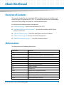
Overview of Contents
This manual is intended for users interested in RHEL installation, hypervisor installation, and
Utilities Package (UP) support on ATCA-7367. It is assumed that user has basic understanding
of Linux/Unix, Networking, AdvancedTCA® , and telecommunications.
It is divided into the following chapters and appendix:
Introduction on page 13, gives an overview about ATCA-7367.
Installation of RHEL Server Edition on page 17, describes the installation of RHEL Server
Edition on ATCA-7367.
Hypervisor Support on page 79, describes about hypervisor and its installation.
Utilities Package on page 89, describes the Utilities Package (UP).
Related Documentation on page 171, lists all the related documents.
Abbreviations
This document uses the following abbreviations:
Abbreviation
Definition
AMC
Advanced Mezzanine Card
ATCA
Advanced Telecommunications Computing Architecture
BBS
Basic Blade Service
BCM
Board Control Module
BIOS
Basic Input/Output System
BSD
Berkeley Software Distribution
UP
Utilities Package
CD
Compact Disc
DHCP
Dynamic Host Configuration Protocol
DVD
Digital Versatile Disc
FCU
Firmware Upgrade Command-line Utility
FPGA
Field Programmable Gate Array
ATCA-7367 RHEL 5.6 User Guide (6806800M98B)
9
About this Manual
10
About this Manual
Abbreviation
Definition
FRI
Firmware Recovery Image
FTP
File Transfer Protocol
FUF
Firmware Upgrade Facility
HPM
Hardware Platform Management
HTTP
Hyper Text Transfer Protocol
I/O
Input /output
IPMC
Intelligent Platform Management Controller
KVM
Kernel Based Virtual Machine
LUN
Logical Unit Number
MMC
Module Management Controller
NFS
Network File System
PCI
Peripheral Component Interconnect
PICMG
PCI Industrial Computer Manufactures Groups
PXE
Preboot Execution Environment
RAID
Redundant Array of Independent Disks
RHEL
Red Hat Enterprise Linux
RTM
Rear Transmission Module
TFTP
Trivial File Transfer Protocol
UP
Utilities Package
VNC
Virtual Network Computing
ATCA-7367 RHEL 5.6 User Guide (6806800M98B)
About this Manual
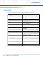
Conventions
The following table describes the conventions used throughout this manual.
Notation
Description
0x00000000
Typical notation for hexadecimal numbers (digits are
0 through F), for example used for addresses and
offsets
0b0000
Same for binary numbers (digits are 0 and 1)
bold
Used to emphasize a word
Screen
Used for on-screen output and code related elements
or commands in body text
Courier + Bold
Used to characterize user input and to separate it
from system output
Reference
Used for references and for table and figure
descriptions
File > Exit
Notation for selecting a submenu
<text>
Notation for variables and keys
[text]
Notation for software buttons to click on the screen
and parameter description
...
Repeated item for example node 1, node 2, ..., node
12
.
Omission of information from example/command
that is not necessary at the time being
.
.
..
Ranges, for example: 0..4 means one of the integers
0,1,2,3, and 4 (used in registers)
|
Logical OR
ATCA-7367 RHEL 5.6 User Guide (6806800M98B)
11
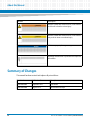
About this Manual
About this Manual
Notation
Description
Indicates a hazardous situation which, if not avoided,
could result in death or serious injury
Indicates a hazardous situation which, if not avoided,
may result in minor or moderate injury
Indicates a property damage message
No danger encountered. Pay attention to important
information
Summary of Changes
This manual has been revised and replaces all prior editions.
12
Part Number
Publication Date
Description
6806800M98A
September 2011
First edition
6806800M98B
August 2014
Re-branded to Artesyn
ATCA-7367 RHEL 5.6 User Guide (6806800M98B)
Chapter 1
Introduction
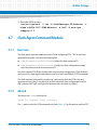
1.1
Overview
The ATCA-7367 is a high performance single processor AdvancedTCA server blade and ATCA
node board, designed according to PICMG 3.0 Revision 3.0 ATCA Base Specification. ATCA-7367
is a single board computer that offers a powerful processing complex through a single six-core
Intel Westmere-EP processor, and supports up to 48GB DDR3 memory. Furthermore ATCA7367 provides local storage (Onboard SATA disk/SATA Cube, onboard flash disk, or through the
RTM), standard I/O and redundant Gigabit Ethernet connections to the back plane's Base
Interfaces (PICMG3.0) and Fabric Interfaces (PICMG 3.1Option1,9). Another important feature
is that ATCA-7367 provides AMC support and is compatible with different AMC boards to meet
the application-specific requirements. The ATCA-7367 provides system management
capabilities and is hot swap compatible based on the ATCA specification.
The following lists the main features of ATCA-7367:
Form factor: Single slot ATCA (280mm x 322mm)
Processor: Intel Westmere-EP Six-Core processor (Intel XEON 5600 series), Drop-in
compatible with Intel Nehalem-EP processor (Intel XEON 5500 Series)
North Bridge: Xeon 5520 (Tylersburg IOH36 D)
–
Provides two QPI interfaces for connecting to up to two Intel Xeon processors
–
Provides 36 PCI-e Gen2 lanes, Intel Virtualization Technology, ESI interface and
Management Engine
–
FC-BGA 37.5mm x 37.5 mm, 1295 balls
South Bridge: ICH10R, ESI connection to Xeon 5520 (Tylersburg IOH36 D)
–
Provides extensive I/O support and Boot path to redundant SPI Boot flashes
–
I/O interfaces include SATA, USB2.0, LAN, LPC interface, RTC with WDT
Base interface : Dual 10/100/1000Base-T Ethernet
Fabric Interface: Dual 1G/10Gbps Ethernet interfaces, support PICMG3.1 option 1 and 9
Update Channel: One 10/100/1000Base-T, and SAS ports
RTM Interface
–
Five PCI-e x4
–
8-Port AMC I/O
ATCA-7367 RHEL 5.6 User Guide (6806800M98B)
13
Introduction
–
2x SAS Ports (SAS controller is on RTM)
–
1x SATA port
–
3x Telecom Clock
–
1x UART and 1x USB interfaces
–
IPMI Management bus
One AMC slot
–
GE on ports 0, 1, 8, 9, 10, 11
–
PCIe x4 on ports 4-7
–
SAS on port 2, SATA on port3
–
Port 13-20 to Zone 3
–
TCLK and FCLK support
Front Panel
–
One 10/100/1000BASE-T Ethernet
–
Two USB2.0 Ports
–
One serial console
BIOS Chip: Up to 1 MB onboard Boot and 1 MB Recovery Boot Flash (SPI)
Onboard storage support
–
2.5 Inch SATA HDD
–
SATA Cube (SSD): 16, 32, 64, 128 GB capacity
–
USB flash (EUSB SDD), 1, 2 or 4 GB capacity
Onboard IPMC (IPMI management controller) implements IPMI version 1.5
Onboard Glue Logic FPGA for IPMC extension and onboard control register
The ATCA-7367 supports:
14
RHEL 5 update 6 (and further updates) Server Edition
Xen and KVM Hypervisor on RHEL 5 update 6 (and further updates) Server Edition
ATCA-7367 RHEL 5.6 User Guide (6806800M98B)
Introduction
For more information on ATCA-7367, refer http://www.artesyn.com/computing/
Throughout this manual, RHEL 5 refers to 32 bit and 64 bit version of RHEL 5.
ATCA-7367 RHEL 5.6 User Guide (6806800M98B)
15
Introduction
16
ATCA-7367 RHEL 5.6 User Guide (6806800M98B)
Chapter 2
Installation of RHEL Server Edition
2.1
Overview
The ATCA-7367 supports RHEL 5 update 6 (and further updates) Server Edition operating
system.
This chapter describes the installation of RHEL 5 update 6 Server Edition and the same
procedure can be followed for installing further updates of RHEL 5. For specific instructions on
installation, refer http://www.redhat.com/docs/manuals/enterprise/RHEL-5manual/Installation_Guide-en-US/index.html
Installation of RHEL 5 update 6 Server Edition over serial console or VNC can be done using
following methods:
CDs/DVD
PXE Network-Based Installation
The ATCA-7367 supports RHEL text mode installation over serial console, and graphical mode
installation using VNC.
2.2
RHEL 5 Update 6 Server Edition Installation using
CDs or DVD
The following sections describe the RHEL installation in text mode and graphical mode using
CDs or DVD.
ATCA-7367 RHEL 5.6 User Guide (6806800M98B)
17
Installation of RHEL Server Edition
2.2.1
Prerequisites
You should have the following software and peripherals before starting installation:
Installation CDs or DVDs of RHEL 5 update 6 Server Edition
USB CD-ROM for installation using CDs of RHEL, or USB DVD-ROM for installation using
DVD of RHEL
VNC viewer, if you want to do installation in graphical mode
To install 32 bit operating system, use x86 CDs or DVD of RHEL and for 64 bit operating
system use x86_64 CDs or DVD of RHEL.
2.2.2
Installation Setup
This section explains the procedure required to create installation setup for installation using
CDs/DVD.
Procedure
1. Connect serial console cable to front panel of the blade and access serial console
using the following settings.
baud rate: 9600
data bits: 8
parity: none
stop bit: 1
hardware control: none
2. Connect USB CD-ROM or DVD-ROM to any USB port of the blade or RTM-ATCA7360 .
18
ATCA-7367 RHEL 5.6 User Guide (6806800M98B)
Installation of RHEL Server Edition
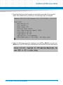
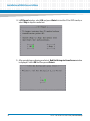
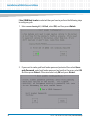
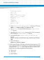
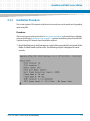
3. Reset the blade using shelf manager or reset button provided at front panel of
blade. When blade boots up after reset, the following output is displayed.
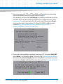
4. When the following screenshot is displayed, press <F2> or <Del> key to enter into
BIOS menu to set CD-ROM as first boot device and hard disk as second boot device.
ATCA-7367 RHEL 5.6 User Guide (6806800M98B)
19
Installation of RHEL Server Edition
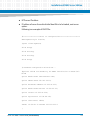
When <F2> or <Del> key is pressed, BIOS window is displayed on serial console.
20
ATCA-7367 RHEL 5.6 User Guide (6806800M98B)
Installation of RHEL Server Edition
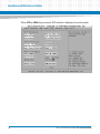
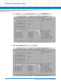
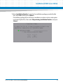
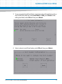
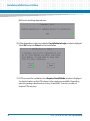
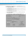
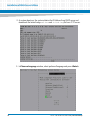
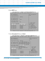
5. Select Boot menu using left or right arrow keys.
ATCA-7367 RHEL 5.6 User Guide (6806800M98B)
21
Installation of RHEL Server Edition
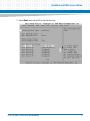
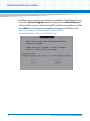
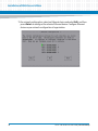
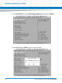
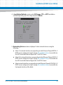
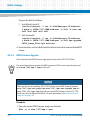
6. Select Boot option #1 and then press <Enter>.
22
ATCA-7367 RHEL 5.6 User Guide (6806800M98B)
Installation of RHEL Server Edition
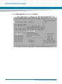
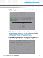
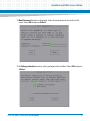
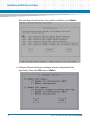
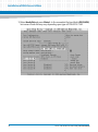
7. Select USBCDROM device and then press <Enter>.
ATCA-7367 RHEL 5.6 User Guide (6806800M98B)
23
Installation of RHEL Server Edition
When <Enter> is pressed, Boot option #1 changes to USBCDROM device.
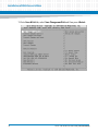
8. Select Boot option #2 and then press <Enter>.
24
ATCA-7367 RHEL 5.6 User Guide (6806800M98B)
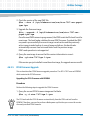
Installation of RHEL Server Edition
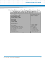
9. Select hard disk and then press <Enter>.
In the screenshot hard disk is ID00 LUN0, but name of hard disk may vary
depending upon type of RTM-ATCA-7360. For example, hard disk may also be
shown as Elx 00 500000E011B0C0B1,00 0F 1 on RTM-ATCA-7360-FC.
ATCA-7367 RHEL 5.6 User Guide (6806800M98B)
25
Installation of RHEL Server Edition
When <Enter> is pressed, Boot option #2 changes to hard disk.
26
ATCA-7367 RHEL 5.6 User Guide (6806800M98B)
Installation of RHEL Server Edition
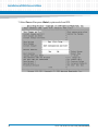
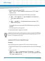
10.Go to Save & Exit menu, select Save Changes and Exit and then press <Enter>.
ATCA-7367 RHEL 5.6 User Guide (6806800M98B)
27
Installation of RHEL Server Edition
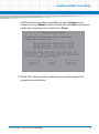
11.Select Yes and then press <Enter>, system exits from BIOS.
28
ATCA-7367 RHEL 5.6 User Guide (6806800M98B)
Installation of RHEL Server Edition
2.2.3
Text Mode Installation
Procedure
After meeting prerequisites described in section Prerequisites on page 18 and completing
installation setup as described in Installation Setup on page 18, perform following steps for
installation in text mode over serial console:
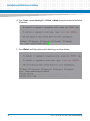
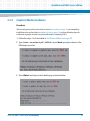
1. Insert CD1 or DVD of RHEL 5 update 6 Server Edition in DVD/CD-ROM.
2. Reset the blade using shelf manager or reset button provided at front panel of the
blade. When blade boots up after the reset, the following output is displayed.
3. The blade boots up with CD1 or DVD, and boot: prompt as shown in the below
screenshot.
ATCA-7367 RHEL 5.6 User Guide (6806800M98B)
29
Installation of RHEL Server Edition
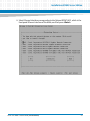
4. Type linux console=ttyS0,9600n8 at boot: prompt as shown in the below
screenshot.
5. Press <Enter> and then system starts booting up as shown below.
30
ATCA-7367 RHEL 5.6 User Guide (6806800M98B)
Installation of RHEL Server Edition
6. In Choose a Language window, select preferred language, and then press <Enter>.
7. In Installation Method window, select Local CDROM, and then press <Enter>.
ATCA-7367 RHEL 5.6 User Guide (6806800M98B)
31
Installation of RHEL Server Edition
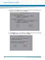
8. In CD Found window, select OK and press <Enter> to test the CD or DVD media, or
select Skip to skip the media test.
9. After completing or skipping media test, Red Hat Enterprise Linux Server window
is displayed. Select OK and then press <Enter>.
32
ATCA-7367 RHEL 5.6 User Guide (6806800M98B)
Installation of RHEL Server Edition
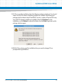
10.Enter Installation Number located in the installation package provided by Red
Hat, select OK and then press <Enter>.
If installation package does not have an installation number and user subscription
is activated by Red Hat, then select Skip entering Installation Number and press
<Enter>.
ATCA-7367 RHEL 5.6 User Guide (6806800M98B)
33
Installation of RHEL Server Edition
11.Installation process searches for existing Linux installation. If installation of Linux is
found then System to Upgrade window is displayed, select Reinstall System to
freshly install the system or select existing RHEL installation to upgrade it, and then
press <Enter>. For information on upgrading existing Linux installation, refer
http://www.redhat.com/docs/manuals/enterprise/RHEL-5manual/Installation_Guide-en-US/ch02s01.html
34
ATCA-7367 RHEL 5.6 User Guide (6806800M98B)
Installation of RHEL Server Edition
12.In Partitioning Type window, select devices to be used for installation and press
<Enter>.
13.Perform disk partitioning of the devices selected in the previous step, using
guidelines given under section 4.15 to 4.18 of RHEL Installation Guide located at
http://www.redhat.com/docs/manuals/enterprise/RHEL-5manual/Installation_Guide-en-US/s1-diskpartsetup-x86.html
14.In Boot Loader Configuration window, select Use GRUB Boot Loader to install
grub boot loader or No Boot Loader, then select OK and press <Enter>.
ATCA-7367 RHEL 5.6 User Guide (6806800M98B)
35
Installation of RHEL Server Edition
If Use GRUB Boot Loader is selected then you have to perform the following steps
to configure grub:
1. Enter console=ttyS0,9600n8, select OK, and then press <Enter>.
2. If you want to make grub boot loader password protected then select Use a
grub Password, enter boot loader password and confirm the same, select OK
and then press <Enter>. Otherwise select only OK and press <Enter>.
36
ATCA-7367 RHEL 5.6 User Guide (6806800M98B)
Installation of RHEL Server Edition
3. You are prompted to edit boot label, output depends on disk partitioning. If you
want to edit boot label then select boot label and Edit, press <Enter>. After
editing boot label, select OK and then press <Enter>.
4. Select a device to install boat loader, select OK and then press <Enter>.
ATCA-7367 RHEL 5.6 User Guide (6806800M98B)
37
Installation of RHEL Server Edition
15.For network configuration, select an Ethernet device and select Edit, and then
press <Enter> to configure the selected Ethernet device. Configure Ethernet
devices as per network configuration of organization.
38
ATCA-7367 RHEL 5.6 User Guide (6806800M98B)
Installation of RHEL Server Edition
16.If host name of the blade is assigned by DHCP server and dynamic network
configuration is done in previous step, then select automatically via DHCP.
Otherwise select manually and enter desired host name. Select OK and press
<Enter>.
ATCA-7367 RHEL 5.6 User Guide (6806800M98B)
39
Installation of RHEL Server Edition
17.Select System clock uses UTC to use UTC time, then select OK and press <Enter>.
Otherwise you can select time zone based upon the location, select OK and press
<Enter>.
40
ATCA-7367 RHEL 5.6 User Guide (6806800M98B)
Installation of RHEL Server Edition
18.Root Password window is displayed. Enter desired password and confirm the
same. Select OK and press <Enter>.
19.In Package selection window, select packages to be installed. Select OK and press
<Enter>.
ATCA-7367 RHEL 5.6 User Guide (6806800M98B)
41
Installation of RHEL Server Edition
RHEL starts checking dependencies.
20. When dependency check is completed, Installation to begin window is displayed.
Select OK and press <Enter> to start installation.
21. If CDs are used for installation then Required Install Media window is displayed.
You should make sure that CDs shown in the window are available. Depending
upon the package selection done in step 19 and RHEL 5 version, number of
required CDs may vary.
42
ATCA-7367 RHEL 5.6 User Guide (6806800M98B)
Installation of RHEL Server Edition
If all CDs shown in the window are available, then select Continue to start
installation or select Reboot to reboot the blade, else select Back to go back and
modify selected packages to be installed. Press <Enter>.
22.If RHEL CDs are being used for installation then you need to change CDs as
prompted during installation.
ATCA-7367 RHEL 5.6 User Guide (6806800M98B)
43
Installation of RHEL Server Edition
23.When installation of RHEL Server Edition is completed, Complete window is
displayed. Remove installation CD or DVD, select Reboot and press <Enter> to
reboot the blade.
24.After the reboot, the blade boots up with RHEL. During boot up Setup Agent utility
is displayed to changes and configure RHEL. You can configure the system, else
select Exit and then press <Enter> to continue boot up of the blade.
25.As system boots up, login prompt is shown, enter user name as root and
password as entered in step 18, page 41.
26. Register the blade with Red Hat Network using guidelines at:
https://rhn.redhat.com/rhn/help/reference/rhn500/en/s1-registration-yum.jsp
44
ATCA-7367 RHEL 5.6 User Guide (6806800M98B)
Installation of RHEL Server Edition
2.2.4
Graphical Mode Installation
Procedure
After meeting prerequisites described in section Prerequisites on page 18 and completing
installation setup as described in Installation Setup on page 18, perform following steps for
installation in graphical mode using Virtual Network Computing (VNC):
1. Follow the steps 1 to 3 described in Text Mode Installation on page 29.
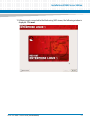
2. Type linux console=ttyS0,9600n8 vnc at boot: prompt as shown in the
following screenshot.
3. Press <Enter> and system starts booting up as shown below.
ATCA-7367 RHEL 5.6 User Guide (6806800M98B)
45
Installation of RHEL Server Edition
4. In Choose a language window, select preferred language and press <Enter>.
5. In Installation Method window, select Local CDROM and press <Enter>.
46
ATCA-7367 RHEL 5.6 User Guide (6806800M98B)
Installation of RHEL Server Edition
6. Select Ethernet interface corresponding to Intel chipset 82567LM-2, which is the
front panel Ethernet interface of the blade, and then press <Enter>.
ATCA-7367 RHEL 5.6 User Guide (6806800M98B)
47
Installation of RHEL Server Edition
7. Configure the front panel Ethernet interface according to network configuration of
organization, select OK and then press <Enter>.
8. In the CD Found window, select OK and press <Enter> to test the CD or DVD media
or select Skip to skip the media test and press <Enter>.
48
ATCA-7367 RHEL 5.6 User Guide (6806800M98B)
Installation of RHEL Server Edition
9. After completing or skipping media test, you are prompted to select User text
mode or Start VNC method for installation. Select Start VNC and press <Enter>.
10. If authentication is required while connecting to the blade using VNC viewer, then
enter VNC server password and confirm it, or select No password and press
<Enter>.
ATCA-7367 RHEL 5.6 User Guide (6806800M98B)
49
Installation of RHEL Server Edition
11.After completing VNC configuration, VNC server starts on the blade. Start VNC
viewer on your system and connect VNC Server running on the blade. For example
as shown in screenshot, VNC server is running on 10.130.98.96:1, hence you need
to use10.130.98.96:1 to connect to the blade. If you are prompted for
authentication then enter password which has been entered in last step.
50
ATCA-7367 RHEL 5.6 User Guide (6806800M98B)
Installation of RHEL Server Edition
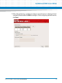
12. When you get connected to the blade using VNC viewer, the following window is
displayed. Click next.
ATCA-7367 RHEL 5.6 User Guide (6806800M98B)
51
Installation of RHEL Server Edition
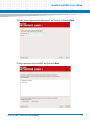
13. Enter Installation Number located in the installation package provided by Red
Hat and click OK. If installation package does not have an installation number and
user subscription is activated by Red Hat, then select Skip entering Installation
Number and click OK.
52
ATCA-7367 RHEL 5.6 User Guide (6806800M98B)
Installation of RHEL Server Edition
14.Installation process searches for existing Linux installation. If installation of Linux is
found then System to Upgrade window is displayed, click Install Red Hat
Enterprise Linux Server to freshly install the system, or Upgrade an existing
Installation to upgrade existing RHEL Server installation. Click Next. For
information on upgrading existing linux installation, refer
http://www.redhat.com/docs/manuals/enterprise/RHEL-5manual/Installation_Guide-en-US/ch02s01.html
15.Select devices to be used for installation and do disk partitioning using guidelines
given under section 4.15 to 4.18 of RHEL Installation Guide located at
http://www.redhat.com/docs/manuals/enterprise/RHEL-5manual/Installation_Guide-en-US/s1-diskpartsetup-x86.html
ATCA-7367 RHEL 5.6 User Guide (6806800M98B)
53
Installation of RHEL Server Edition
After disk partitioning, click Next.
16.If installation is about to erase existing data on disk, then following warning
message is displayed. Click Yes or No, depending on whether the existing data
should be erased or not. If you do not want to erase existing data on disk then click
No and do disk partitioning again.
54
ATCA-7367 RHEL 5.6 User Guide (6806800M98B)
Installation of RHEL Server Edition
17.After disk partitioning, a window to configure network devices is displayed. Select
a network interface and click Edit to configure. After configuring network devices,
click Next.
ATCA-7367 RHEL 5.6 User Guide (6806800M98B)
55
Installation of RHEL Server Edition
18.Select System clock uses UTC, or change the region according to your location,
and then click Next.
56
ATCA-7367 RHEL 5.6 User Guide (6806800M98B)
Installation of RHEL Server Edition
19. Enter desired password for root account and confirm it, then click Next.
20.Select packages to be installed, and then click Next.
ATCA-7367 RHEL 5.6 User Guide (6806800M98B)
57
Installation of RHEL Server Edition
21.Checking dependencies starts.
22. Click Next and press <Enter> to start installation.
58
ATCA-7367 RHEL 5.6 User Guide (6806800M98B)
Installation of RHEL Server Edition
23.If CDs are used for installation then the following window is displayed. You should
make sure that CDs shown in following window are available. Depending upon
package selection done in step 20 and RHEL 5 version, number of required CDs may
vary. If all CDs shown in window are available, then click Continue to start
installation, or click Reboot to reboot the blade, else click Back to go back and do
package selection again.
24.If RHEL CDs are being used for installation then you need to change CDs as
prompted during installation.
ATCA-7367 RHEL 5.6 User Guide (6806800M98B)
59
Installation of RHEL Server Edition
25.When installation is completed, remove installation CD or DVD, and then click
Reboot to reboot the blade.
26.When system comes up after reboot, Setup Agent utility window is displayed to
changes and configure system. Select Exit and press <Enter> to continue boot up
of the blade.
27.When system boots up after reboot, login prompt is displayed. Enter user name as
root and password as entered in step 19, page 57.
28.Register the blade with Red Hat Network using guidelines given at:
https://rhn.redhat.com/rhn/help/reference/rhn500/en/s1-registration-yum.jsp
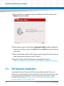
2.3
PXE Network Installation
Using Preboot Execution Environment (PXE) network installation method, RHEL can be
installed over network using Network File System (NFS), File Transfer Protocol (FTP), or Hyper
Text Transfer Protocol (HTTP) protocols. For more information refer, chapter 31 of RHEL
installation Guide located at http://www.redhat.com/docs/manuals/enterprise/RHEL-5manual/Installation_Guide-en-US/index.html
60
ATCA-7367 RHEL 5.6 User Guide (6806800M98B)
Installation of RHEL Server Edition
You can do installation in text mode and graphical mode using PXE network installation
method.
2.3.1
Prerequisites
You need to meet following prerequisites:
The blade is connected directly or indirectly to Trivial File Transfer Protocol (TFTP) or
Dynamic Host Configuration Protocol (DHCP) server over Ethernet.
The blade is connected directly or indirectly to NFS, FTP, or HTTP Server having installation
tree over Ethernet.
You should have following software before starting installation:
Installation CDs or DVD or ISO image of RHEL 5 update 6 Server Edition
VNC viewer, if you want to do installation in graphical mode
To install 32 bit operating system, use x86 iso image or install CDs of RHEL 5 update 6 and for
64 bit operating system use x86_64 iso image or install CDs of RHEL 5 update 6.
2.3.2
Installation Setup
Procedure
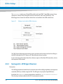
1. Prepare for PXE based network installation using guidelines given under section 2.5
of RHEL Installation Guide located at,
http://www.redhat.com/docs/manuals/enterprise/RHEL-5manual/Installation_Guide-en-US/index.html
2. Configure standard TFTP servers, Berkeley Software Distribution (BSD) compatible
1. Login to TFTP server using root account.
2. Create the file /etc/xinetd.d/tftp with the following contents.
service tftp
ATCA-7367 RHEL 5.6 User Guide (6806800M98B)
61
Installation of RHEL Server Edition
{
socket_type = dgram
wait = yes
user = root
server = /usr/sbin/in.tftpd
server_args = -s /tftpboot
per_source = 11
cps=100 2
flags=IPv4
disable = no
protocol = udp
}
3. Create /tftpboot/ATCA-7367/pxelinux.cfg directory on TFTP server.
#mkdir -p /tftpboot/ATCA-7367/pxelinux.cfg
4. Copy pxelinux.0 from the SYSLINUX distribution in /tftpboot/ATCA7367 directory.
5. Copy all files from images/pxeboot directory of CD1, DVD, or iso image of
RHEL installation in /tftpboot/ATCA-7367 directory.
6. Create default file inside /tftpboot/ATCA-7367/pxelinux.cfg
directory.
default vmlinuz initrd=initrd.img console=ttyS0,9600n8
text
7. Restart TFTP daemon.
#/etc/init.d/xinetd restart
3. In order to assign IP address to the blade and download a boot image from a TFTP
server, configure the DHCP server. The DHCP server is typically configured through
a configuration file dhcpd.conf. Many configurable options can be left at their
default values, but configure the following minimum options:
62
Domain name
Subnet mask
Router IP address
ATCA-7367 RHEL 5.6 User Guide (6806800M98B)
Installation of RHEL Server Edition
NTP server IP address
IP address of server from which initial boot file is to be loaded, next server
option.
Following is an example of DHCP file:
#*******************start of configuration***********************
ddns-update-style interim;
ignore client-updates;
allow bootp;
allow booting;
allow booting;
allow bootp;
# Standard configuration directives...
#options fields are mandatory for RHEL installation on ATCA-7367
blade
option domain-name "www.emerson.com";
option subnet-mask 255.255.255.0;
option broadcast-address 10.232.91.255;
option domain-name-servers 10.232.22.25;
option routers 10.232.91.254;
option ntp-servers 10.232.88.125;
option time-offset 18000;
subnet 10.232.91.0 netmask 255.255.255.0
{
ATCA-7367 RHEL 5.6 User Guide (6806800M98B)
63
Installation of RHEL Server Edition
range 10.232.91.10 10.232.91.40;#mandatory
next-server 10.232.88.125; #mandatory
filename "ATCA-7367/pxelinux.0"; # mandatory
# ATCA-7367/pxelinux.0 this is the place where we expect
# to pick the pxe configuration from, please read point 4 of above
step 2
}
After editing /etc/dhcpd.conf, restart the DHCP server on interface which
should be used for assigning IP address to the blade. For more information,
refer dhcpd.conf linux man page located at
http://linux.die.net/man/5/dhcpd.conf and dhcpd linux man page located at
http://linux.die.net/man/8/dhcpd
4. Follow steps 1 through 6 described in Installation Setup on page 18.
64
ATCA-7367 RHEL 5.6 User Guide (6806800M98B)
Installation of RHEL Server Edition
5. Select Base Network 1, Base Network 2, or FrontPanel Network depending on
the following and press <Enter>:
Select Base Network 1, if DHCP server is configured and running on the ATCA
controller blade of logical slot 1 in chassis.
Select Base Network 2, if DHCP server is configured and running on the ATCA
controller blade of logical slot 2 in chassis.
Select FrontPanel Network, if DHCP server is accessible by using the front
panel interface of blade.
ATCA-7367 RHEL 5.6 User Guide (6806800M98B)
65
Installation of RHEL Server Edition
6. Go to Save & Exit tab, select Save Changes and Exit and then press <Enter>.
7. Select Yes and press <Enter>. System exits from BIOS.
66
ATCA-7367 RHEL 5.6 User Guide (6806800M98B)
Installation of RHEL Server Edition
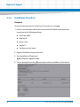
2.3.3
Installation Procedure
This section explains PXE network installation in text mode over serial console and in graphical
mode using VNC.
Procedure:
After meeting prerequisites described in Prerequisites on page 61 and completing installation
setup as described in Installation Setup on page 61, perform the following steps to install RHEL
5 update 6 using PXE Network-Based Installation method.
1. Reset the blade using shelf manager or reset button provided at front panel of the
blade. As blade boots up after reset, the following output is displayed on serial
console.
ATCA-7367 RHEL 5.6 User Guide (6806800M98B)
67
Installation of RHEL Server Edition
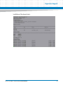
2. As system boots up, the system obtains the IP Address from DHCP server and
downloads the kernel image vmlinuz and initrd.img file from TFTP server.
3. In Choose a Language window, select preferred language and press <Enter>.
68
ATCA-7367 RHEL 5.6 User Guide (6806800M98B)
Installation of RHEL Server Edition
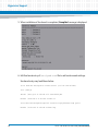
4. In Installation Method window, select NFS image, FTP, or HTTP installation
method depending upon the setup and press <Enter>.
5. Networking Device window is displayed. Select network devices using the
following:
Select 1st network interface corresponding to Intel Ethernet Chipset 82576, if
DHCP server configured in step 3 of page 62, Installation Setup is accessible via
the ATCA controller blade of logical slot 1 of ATCA Chassis.
Select 2nd network interface corresponding to Intel Ethernet Chipset 82576, if
DHCP server configured in step 3 of page 62, Installation Setup is accessible via
the ATCA controller blade of logical slot 2 of ATCA Chassis.
Select network interface corresponding to Intel Ethernet Chipset 82567LM-2, if
DHCP server configured in step 3 of page 62, Installation Setup is accessible via
front panel interface of the blade.
ATCA-7367 RHEL 5.6 User Guide (6806800M98B)
69
Installation of RHEL Server Edition
After selecting network interface to be used for installation, press <Enter>.
6. Configure Ethernet interface according to network configuration of the
organization, then select OK and press <Enter>.
70
ATCA-7367 RHEL 5.6 User Guide (6806800M98B)
Installation of RHEL Server Edition
7. Enter server name NFS, FTP, or HTTP and RHEL installation directory depending
upon the installation method entered in step 4 on page 69.
For example, if you have selected NFS image as installation method in step 4 then
first enter NFS server name, RHEL server directory as configured in step 1 under
Installation Setup and mount option for NFS image, select OK and press <Enter>.
For more information, refer sections 4.7, 4.8 and 4.9 of RHEL installation guide
located at http://www.redhat.com/docs/manuals/enterprise/RHEL-5manual/Installation_Guide-en-US/index.html
8. If you want to do installation in graphical mode using VNC then select Start VNC,
press <Enter>, and then follow steps 10 through 25 of Graphical Mode Installation.
Otherwise select User text mode method to install RHEL in text mode over serial
console, press <Enter>, and then follow steps 9 through 23 of Text Mode Installation.
ATCA-7367 RHEL 5.6 User Guide (6806800M98B)
71
Installation of RHEL Server Edition
9. When the following window is displayed, press <F2> or <Del> key to enter into BIOS
menu.
When <F2> or <Del> key is pressed, BIOS window is visible on serial console.
72
ATCA-7367 RHEL 5.6 User Guide (6806800M98B)
Installation of RHEL Server Edition
10.Select BOOT menu.
11. Select Boot option #1 and press <Enter>.
ATCA-7367 RHEL 5.6 User Guide (6806800M98B)
73
Installation of RHEL Server Edition
12.Select hard disk and press <Enter>. In the screenshot the hard disk is ID00 LUN0,
but name of hard disk may vary depending upon type of RTM-ATCA-7360.
74
ATCA-7367 RHEL 5.6 User Guide (6806800M98B)
Installation of RHEL Server Edition
When <Enter> is pressed, Boot option #1 changes to hard disk.
ATCA-7367 RHEL 5.6 User Guide (6806800M98B)
75
Installation of RHEL Server Edition
13.Go to Save & Exit tab, select Save Changes and Exit and then press <Enter>.
76
ATCA-7367 RHEL 5.6 User Guide (6806800M98B)
Installation of RHEL Server Edition
14.Select Yes and press <Enter>. The system exits from BIOS.
15.As system boots up with RHEL, Setup Agent utility is displayed. Configure the
system, and select Exit and then press <Enter> to continue to boot up the blade.
16.As system boots up login prompt is shown, enter user name as root and password
to login to system using root account.
17.Register the blade with Red Hat Network using guidelines given at
https://rhn.redhat.com/rhn/help/reference/rhn500/en/s1-registration-yum.jsp
ATCA-7367 RHEL 5.6 User Guide (6806800M98B)
77
Installation of RHEL Server Edition
78
ATCA-7367 RHEL 5.6 User Guide (6806800M98B)
Chapter 3
Hypervisor Support
3.1
Overview
A hypervisor, also called virtual machine manager, is a piece of software or hardware platform
virtualization that allows multiple operating systems to run on a host computer concurrently.
The ATCA-7367 blade supports Xen and KVM hypervisor.
Following sections describes the method to install Xen and KVM hypervisor on the ATCA-7367
blade.
3.2
Installation of Xen Hypervisor
Xen hypervisor is the fastest and most secure infrastructure virtualization solution available
today, supporting a wide range of guest operating systems including Windows®, Linux®,
Solaris®, and various versions of the BSD operating systems.
With Xen virtualization, a thin software layer known as the Xen hypervisor is inserted between
the server hardware and the operating system. This provides an abstraction layer that allows
each physical server to run one or more virtual servers, effectively decoupling the operating
system and its applications from the underlying physical server.
3.2.1
Prerequisites
Following are the prerequisites for installing Xen hypervisor on the ATCA-7367 blade:
RHEL 5 update 6 (or any further update) server edition is installed on the blade.
The blade is connected with Red Hat Network, if not then register the blade with Red Hat
Network using guidelines given at:
https://rhn.redhat.com/rhn/help/reference/rhn500/en/s1-registration-yum.jsp
ATCA-7367 RHEL 5.6 User Guide (6806800M98B)
79
Hypervisor Support
3.2.2
Installation Procedure
Procedure
Perform the following steps for installation of Xen hypervisor using yum:
1. Connect serial console cable to the front panel of the blade and access serial
console using the following settings.
baud rate: 9600
data bits: 8
parity: none
stop bit: 1
hardware control: none
2. Login on the blade using root account.
3. Start installation of Xen kernel.
#yum install kernel-xen
4. You are prompted to enter y/N, press y to continue installation of Xen kernel.
80
ATCA-7367 RHEL 5.6 User Guide (6806800M98B)
Hypervisor Support
Installation of Xen kernel starts.
ATCA-7367 RHEL 5.6 User Guide (6806800M98B)
81
Hypervisor Support
5. When installation of Xen kernel is completed, Complete! message is displayed.
6. Edit Xen kernel entry of /etc/grub.conf file to add serial console settings.
Xen kernel entry may look like as below:
title Red Hat Enterprise Linux Server (2.6.18-164.el5xen)
root (hd0,0)
kernel /xen.gz-2.6.18-164.el5 com1=9600,8n1
module /vmlinuz-2.6.18-164.el5xen ro
root=/dev/VolGroup00/LogVol02 console=ttyS0,9600n8 rhgb quiet
module /initrd-2.6.18-164.el5xen.img
82
ATCA-7367 RHEL 5.6 User Guide (6806800M98B)
Hypervisor Support
7. Reboot system.
#reboot
8. When system comes up after reboot, select Xen kernel entry in grub menu to boot
system with Xen kernel.
3.3
Installation of KVM Hypervisor
KVM (Kernel-based Virtual Machine) is a full virtualization solution for Linux on x86 hardware
containing virtualization extensions Intel VT or AMD-V. It consists of a loadable kernel module
kvm.ko that provides the core virtualization infrastructure and a processor specific module,
kvm-intel.ko, or kvm-amd.ko.
Using KVM, one can run multiple virtual machines running unmodified Linux or Windows
images. Each virtual machine has private virtualized hardware: a network card, disk, graphics
adapter, etc.
ATCA-7367 RHEL 5.6 User Guide (6806800M98B)
83
Hypervisor Support
3.3.1
Prerequisites
Following are the prerequisites for installing KVM hypervisor on the ATCA-7367 blade:
3.3.2
64bit RHEL 5 update 6 (or any further update) Server Edition is installed on the blade.
The blade is connected with Red Hat Network, if not then register the blade with Red Hat
Network using guidelines given at:
https://rhn.redhat.com/rhn/help/reference/rhn500/en/s1-registration-yum.jsp
Installation Procedure
Procedure
Perform following steps for installation of KVM hypervisor using yum.
1. Follow the steps 1 through 2 described in Installation Procedure on page 80.
2. Start installation of KVM hypervisor.
#yum install kvm
3. You are prompted to enter y/N, press y to install KVM hypervisor.
84
ATCA-7367 RHEL 5.6 User Guide (6806800M98B)
Hypervisor Support
4. When KVM hypervisor installation is completed, Complete! message is displayed.
3.4
Virtualized Guest Installation
After installation of Xen or KVM hypervisor on the blade, you can create guest operating
systems. This section describes the general processes for installing guest operating systems on
virtual machines.
3.4.1
Prerequisites
Following are the prerequisites for virtualized guest installation:
RHEL 5 update 6 (or any further update) Server Edition is installed with Xen and KVM
hypervisor as described in Installation of Xen Hypervisor and Installation of KVM Hypervisor.
VNC server is installed.
The blade is connected with Red Hat Network, if not then register the blade with Red Hat
Network using guidelines given at
https://rhn.redhat.com/rhn/help/reference/rhn500/en/s1-registration-yum.jsp
ATCA-7367 RHEL 5.6 User Guide (6806800M98B)
85
Hypervisor Support
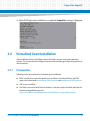
3.4.2
Installation Procedure
Procedure
You need to perform following steps to install virtualized guest operating system:
1. Follow the steps 1 through 2 described in Installation Procedure on page 80.
2. Configure VNC server on the blade using the following steps.
1. Open and edit /etc/sysconfig/vncservers file, to allow VNC access to
root user.
For example, file /etc/sysconfig/vncservers should look like:
VNCSERVERS="2:root"
VNCSERVERARGS[2]="-geometry 1024x768"
2. Open and edit ~/.vnc/xstartup file, to initialize X session whenever you
login on the blade using VNC viewer.
For example, ~/.vnc/xstartup file may look like as below:
#!/bin/sh
# Uncomment the following two lines for normal desktop:
unset SESSION_MANAGER
exec /etc/X11/xinit/xinitrc
[ -x /etc/vnc/xstartup ] && exec /etc/vnc/xstartup
[ -r $HOME/.Xresources ] && xrdb $HOME/.Xresources
xsetroot -solid grey
vncconfig -iconic &
#xterm -geometry 80x24+10+10 -ls -title "$VNCDESKTOP Desktop" &
#twm &
startx &
86
ATCA-7367 RHEL 5.6 User Guide (6806800M98B)
Hypervisor Support
3. Allow VNC based access using password authentication mechanism.
#vncpasswd
4. Start VNC server.
#/etc/init.d/vncserver start
3. Install virtual manager and Xen utilities.
#yum install xen virt-manager
4. Start Xen service.
#/etc/init.d/xend start
5. Disable firewall on system using following command, or configure iptables rules
to enable VNC access.
#/etc/init.d/iptables stop
6. Connect to the blade using VNC viewer. While connecting, you are prompted to
enter <IP address>:<display# >.
Where <IP address> is IP address of the blade, and <display#> is display
number in /etc/sysconfig/vncservers. For example, assuming IP address
of front interface is 192.168.10.8 and /etc/sysconfig/vncservers is edited
as in step 2, you need to enter 192.168.10.8:2 while connecting using VNC viewer.
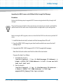
7. Create virtualized guest using guidelines given under Section 6.2 of RHEL
Virtualization Guide located at:
http://www.redhat.com/docs/enUS/Red_Hat_Enterprise_Linux/5.5/html/Virtualization_Guide/sect-VirtualizationVirtualized_guest_installation_overviewCreating_guests_with_virt_manager.html
ATCA-7367 RHEL 5.6 User Guide (6806800M98B)
87
Hypervisor Support
88
ATCA-7367 RHEL 5.6 User Guide (6806800M98B)
Chapter 4
Utilities Package
4.1
Overview
The Utilities Package (UP) for RHEL includes the following components:
4.2
Service Initialization Scripts
Board Control Module (BCM)
Firmware Upgrade Facility (FUF)
Clock Agent Command Module
HPM Agent Command Module
Enhanced ipmitool (ipmitool_pps)
SFMEM Support Module
Igb-ixgbe: drivers for Intel 82576 (igb-3.0.22) and 82599 (ixgbe- 2.0.72.4-NAPI) network
interfaces
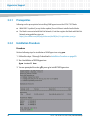
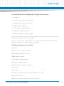
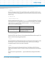
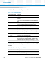
Package Information
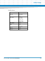
UP software is delivered as a tgz file. For RHEL 5 update 6, the following packages support the
different kernel release.
Table 4-1 Packages of UP for RHEL5.6
4.3
Package name
Description
bsp-<version>.x86_64-rhel56-2.6.18238.el5-linux.tgz
For x86_64 arch with kernel 2.6.18-238.el5
bsp-<version>.x86_64-rhel56-xen2.6.18-238.el5-linux.tgz
For x86_64 arch with kernel xen-2.6.18238.el5
Installation Procedures
ATCA-7367 RHEL 5.6 User Guide (6806800M98B)
89
Utilities Package
4.3.1
Extracting the Package
To extract the package, execute the shell command tar.
# tar -xvf bsp-<version>.x86_64-rhel56-2.6.18-238.el5-linux.tgz
# cd bsp-<version>.x86_64-rhel56-2.6.18-238.el5-linux
You must choose the correct UP package according to your kernel release and kernel arch.
Execute the shell command uname to get your kernel information:
# uname -rm
2.6.18-238.el5 x86_64
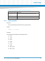
After extracting the package, bsp-<version>.x86_64-rhel56-2.6.18-238.el5linux directory will be created which contains the following subdirectories and files:
4.3.2
up_install.sh: installation shell script
ChangeLog: UP version information file
README: usage introduction of the UP
etc: init scripts of the UP
rpms: rpm packages of UP
rom: rpm packages of firmware
bin: executable binary files
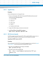
Installing the UP
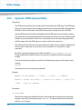
To install UP, execute the shell script up_install.sh.
The script triggers an install wizard, that guides you to make the installation step by step.
# ./ up_install.sh
===== Welcome to ATCA-7367 RedHat EL 5.5 UP installation guide =====
Continue? [Y/N, default is Y]: Y
90
ATCA-7367 RHEL 5.6 User Guide (6806800M98B)
Utilities Package
The installation will install the following MUST packages into your system:
1. BoardCtrl
2. Service Initialization Scripts
3. FUF-Firmware Upgrade Facility
4. SFMEM support Module
5. Clock Agent Command Module
6. HPM Agent Command Module
7. Enhanced ipmitool(ipmitool_pps)
Install the optional igb driver for onboard Intel 82576 1Gb ethernet network
controller? [Y/N, default is N]:Y
Install the optional ixgbe driver for onboard Intel 82599 10Gb ethernet
network controller? [Y/N, default is N]:Y
The following packages are to be installed:
BoardCtrl
Service Initialization Scripts
FUF-Firmware Upgrade Facility
SFMEM support Module
Clock Agent Command Module
HPM Agent Command Module
Enhanced ipmitool(ipmitool_pps)
igb driver
ixgbe driver
Continue? [Y/N/B, B means go back, default Y]: Y
Begins to install......
Begins to install boardctrl, scripts, FUF......
ATCA-7367 RHEL 5.6 User Guide (6806800M98B)
91
Utilities Package
Preparing...
########################################### [100%]
1:bbs-fuf
########################################### [100%]
Preparing...
########################################### [100%]
1:bbs-flashrom
Preparing...
1:bbs-boardctrl
Preparing...
1:bbs-artm-atca7360
########################################### [100%]
########################################### [100%]
########################################### [100%]
########################################### [100%]
########################################### [100%]
……
Finished to install boardctrl, scripts, FUF
Begins to install igb driver......
Preparing...
1:bbs-igb_ixgbe
########################################### [100%]
########################################### [100%]
Finished to install igb driver
Begins to install ixgbe driver......
Finished to install ixgbe driver
Run up for installation......
Begins to restart network......
Finished to restart network......
Installation completed!
After completing the installation, you should run export to add
/opt/bladeservices/bin to the PATH and add /opt/bladeservices/usr/lib to
the LD_LIBRARY_PATH, or logout and login again.
# export PATH=$PATH: /opt/bladeservices/bin
92
ATCA-7367 RHEL 5.6 User Guide (6806800M98B)
Utilities Package
# export
LD_LIBRARY_PATH=$LD_LIBRARY_PATH:/opt/bladeservices/usr/lib
If you choose to install the igb or ixgbe component, the onboard Intel 82576 and 82599
network interfaces services will be restarted.
4.3.3
Uninstalling the UP
To uninstall the installed UP in your blade, execute the shell command up_uninstall.
# up_uninstall
====== Welcome to ATCA-7367 RedHat EL 5.5 UP uninstallation guide ========
Continue? [Y/N, default is Y]: Y
NOTICE: the following installed components will be uninstalled:
1. BoardCtrl
2. Service Initialization Scripts
3. FUF-Firmware Upgrade Facility
4. SFMEM support Module
5. Clock Agent Command Module
6. HPM Agent Command Module
7. Enhanced ipmitool(ipmitool_pps)
8. igb driver
9. ixgbe driver
The following packages are to be uninstalled:
ATCA-7367 RHEL 5.6 User Guide (6806800M98B)
93
Utilities Package
BoardCtrl
Service Initialization Scripts
FUF-Firmware Upgrade Facility
SFMEM support Module
Clock Agent Command Module
HPM Agent Command Module
Enhanced ipmitool(ipmitool_pps)
igb driver
ixgbe driver
Continue? [Y/N/B, B means go back, default Y]: Y
Begins to uninstall......
Begins to uninstall boardctrl, scripts, FUF......
Finished to uninstall boardctrl, scripts, FUF
Begins to uninstall igb driver......
Finished to uninstall igb driver
Begins to uninstall ixgbe driver......
Finished to uninstall ixgbe driver
Run up for uninstallation......
Begins to restart network......
Finished to restart network......
Uninstallation completed!
94
ATCA-7367 RHEL 5.6 User Guide (6806800M98B)
Utilities Package
4.3.4
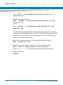
Reinstalling the UP
To reinstall UP, execute the install script up_install.sh in the new package directly.
The script automatically uninstalls any installed version of UP components before making the
new installation.
# ./up_install.sh
Installed UP detected!
Uninstall it and make a new installation? [Y/N, default is N]:Y
Uninstall......
(automatically uninstall)
Make a new installation......
The installation will install the following MUST packages into your system:
1. BoardCtrl
2. Service Initialization Scripts
3. FUF-Firmware Upgrade Facility
4. SFMEM support Module
5. Clock Agent Command Module
6. HPM Agent Command Moudle
7. Enhanced ipmitool(ipmitool_pps)
Install the optional igb driver for onboard Intel 82576 1Gb ethernet network
controller? [Y/N, default is N]:
……
ATCA-7367 RHEL 5.6 User Guide (6806800M98B)
95
Utilities Package
4.4
Service Initialization Scripts
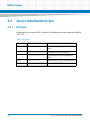
4.4.1
RC Scripts
In addition to the rc-scripts of RHEL 5 update 6, the following start/stop scripts are added to
ATCA-7367.
Table 4-2 RC Scripts
Run Level
Script Name
Description
rc3.d
S02bbsinit.sh
Starts board ctrl driver, ipmi drivers, sfmem
driver
S09ledservicectrl.sh
Front panel LED OOS/IS operation
S22osbootsensor.sh
OS boot status sensor value updating to
IPMC
K02bbsinit.sh
Stop the board ctrl driver and sfmem driver
K09ledservicectrl.sh
Front panel LED OOS/IS operation
rc0.d
96
ATCA-7367 RHEL 5.6 User Guide (6806800M98B)
Utilities Package
4.5
Board Control Module
4.5.1
Overview
Board control is a kernel module which provides access to the board FPGA. The board control
module creates a boardinfo directory in the /proc file system that contains general
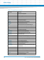
information on the ATCA-7367. The following table describes the information in boardinfo
directory.
File
Description
Sample output
bios_releasedate
Shows the release
date of the currently
installed BIOS.
12/09/2009
board_name
Shows the board
name, as provided by
the BIOS.
ATCA-7367
board_version
Shows the board
version, as provided
by the BIOS.
0106865F01A
ATCA-7367 RHEL 5.6 User Guide (6806800M98B)
97
Utilities Package
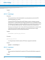
File
Description
Sample output
bios_version
Shows the BIOS
version.
1.0.0
board_serialnumbe
r
Shows the serial
number of the board,
as provided by the
BIOS.
ENG00177
fpga
Shows additional
FPGA information.
FPGA version: 0x0B
. . .
summary
Shows a summary of
the board state
(FPGA registers) and
BIOS provided
information.
Board Vendor:
Emerson
Board Name:
ATCA-7367
Board Version:
0106865F01A....
Board Serial Number: ENG00177....
BIOS Vendor:
Emerson
BIOS Version:
0.0.25G BETA
BIOS Release Date:
12/09/2009
Last Reset Source:
PowerOn CPU
IPMI Cold Reset
Memory Module:
Device/Bank:
DIMM_Socket_P01/Node0_Channel0_Dim
m0
Size:
2048 Mbyte
Data Width:
64 Bit
Manufacturer:
A1_Manufacturer0
Memory Module:
Device/Bank:
DIMM_Socket_P11/Node1_Channel0_Dim
m0
Size:
2048 Mbyte
Data Width:
64 Bit
Manufacturer:
A2_Manufacturer0
IPMI
Interface Type:
1
Control Style)
IPMI Spec Rev:
I2C Slave Addr:
NV Stor.Dev.Addr:
Base Addr:
IRQ:
98
KCS (Keyboard
2.0
0x9A
Not Present
0x00000CA3
0x0
ATCA-7367 RHEL 5.6 User Guide (6806800M98B)
Utilities Package
4.5.2
Board Control Tool
The board control module provides an IOCTL interface which can be used by the userland
applications. The following sections describe userland applications, such as LEDCTRL and
FPGA_TEST.
4.5.2.1
LEDCTRL
Description
Allows to control the 3 front panel LEDs, according to their capabilities.
LEDCTRL can be found at /opt/bladeservices/bin/ledctrl.
Synopsis
ledctl [options] [led1] [led2] ...
Here, led<n> are zero-based LED numbers. If no LED numbers are given, the option is applied
to all the available LEDs.
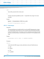
The options can have the following values.
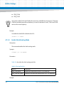
4.5.2.2
Option
Description
-n
Print number of available LEDs.
-i
Display information about LED capabilities.
-s
Print current LED settings.
-c <color>
Set LED(s) <color> to: g[reen], y[ellow], r[ed], b[lue], a[mber], hdd, or
eth.
-b <freq>
Set blink frequency to: off or p[ermanent].
FPGA_TEST
Description
Dumps the FPGA register set. FPGA_TEST can be found at
/opt/bladeservices/bin/fpga_test.
ATCA-7367 RHEL 5.6 User Guide (6806800M98B)
99
Utilities Package
Synopsis
fpga_test -d
Here, -d option is used to dump the complete FPGA register set.
4.6
Firmware Upgrade Facility
4.6.1
Overview
The Firmware Upgrade Facility (FUF) provides a uniform way to upgrade firmware on Artesyn
hub blades and node blades. It consists of a Firmware Upgrade Command-line Utility (FCU),
flash device drivers, and specially prepared firmware recovery image files.
Using FUF, the following firmware types can be upgraded on the ATCA-7367:
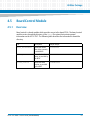
4.6.2
Basic Input/output System (BIOS) firmware
Intelligent Platform Management Controller (IPMC) firmware
Module Management Controller (MMC) firmware on RTM
Field Programmable Gate Array (FPGA) image
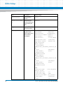
Firmware Recovery Image Files
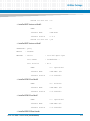
FCU supports specially prepared firmware recovery image (FRI) files and firmware images in
the HPM.1 format. HPM.1 is a PICMG standard to upgrade IPMC.
By default, the image files for the current hardware configurations are loaded as part of the UP
software in /opt/bladeservices/rom when the Utilities Package is installed.
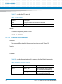
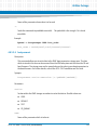
The following image files are currently supported.
Table 4-3 Image Files
100
Filename
Description
atca-7367-cpu-<version>.fri
BIOS image for ATCA-7367 with FRI format
atca-7367-cpu-<version>.hpm
BIOS image for ATCA-7367 with HPM.1
format
ATCA-7367 RHEL 5.6 User Guide (6806800M98B)
Utilities Package
Table 4-3 Image Files
Filename
Description
atca-7367-c01-ipmc.hpm
IPMC firmware for ATCA-7367 variant of
ATCA-7367-C01
atca-7367-amc-poped-ipmc.hpm
IPMC firmware for ATCA-7367 variants with
AMC Bay populated (Including ATCA-73670GB, ATCA-7367-12GB, ATCA-7367-24GB).
atca-7367-amc-no-poped-ipmc.hpm
IPMC firmware for ATCA-7367 variants with
NO AMC Bay populated (Including ATCA7367-0GBLS, ATCA-7367-12GB-LS).
atca-7367-ipmc-c01-boot.hpm
IPMC boot loader for ATCA-7367 variant of
ATCA-7367-C01
atca-7367-ipmc-amc-poped-boot.hpm
IPMC boot loader for ATCA-7367 variants
with AMC Bay populated (Including ATCA7367-0GB, ATCA-7367-12GB, ATCA-736724GB).
atca-7367-ipmc-amc-nopoped-boot.hpm
IPMC boot loader for ATCA-7367 variants
with NO AMC Bay populated (Including
ATCA-7367-0GBLS,
ATCA-7367-12GB-LS).
4.6.3
atca-7367-fpga-<version>.bin
FPGA image in HPM.1 format
artm-7360-ipmc.hpm
IPMC Firmware for ARTM
artm-7360-ipmc-boot.hpm
IPMC boot loader for ARTM
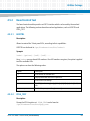
Backup Concept
The BIOS firmware for the ATCA-7367 is stored in redundant and persistent memory devices.
This allows the firmware image in one bank to serve as a backup for the other bank. This is
particularly useful for firmware upgrades.
During normal operation, the CPU on the ATCA-7367 blade determines which bank to boot,
based on a chip select signal controlled by the IPMC. This bank is considered the active boot
device. FCU will only allow you to upgrade an inactive device. FUF allows to upgrade only the
BIOS boot bank from which the blade has not booted. This means that you need to reboot the
blade in case you want to upgrade both the banks of the BIOS flash. The BIOS firmware image
can be programmed via the payload by using FUF or via IPMC.
ATCA-7367 RHEL 5.6 User Guide (6806800M98B)
101
Utilities Package
The IPMC firmware consists of a boot loader as well as an active and a stand-by IPMI firmware.
The boot loader maintains both the active and stand-by firmware in the flash memory of the
ATCA-7367 blade.
Boot loader firmware is not installed in BBS by default, as the boot loader update must be
performed on Artesyn request only.
Each time the IPMC firmware is upgraded, the most recent firmware version is kept in flash
memory and the older firmware version is overwritten by the new one. Once the new IPMI
firmware is programmed, the IPMC resets itself to boot from the new image. The boot loader
validates the new IPMC firmware, provided the IPMC can power up successfully the current
image is made active, and the previously active image is made backup. In case of power-up
failures, the boot loader automatically recovers from crisis and boots from the previous image.
The FPGA bank can be updated via FCU or IPMC. This means that a corrupt FPGA can be
restored using IPMC.
The following sample output displays the information regarding BIOS, IPMI, and FPGA.
Depending on your setup, you may get a different output.
#fcu -q
********************[[[[[REPORT BEGIN]]]]]********************
OPERATION : Query
102
RESULT
: SUCCESS
MESSAGE
: Device
: atca-7367-cpu
Part number
: 0106865F08A....
Part revision
: R1.2.
BANK
: A
Firmware Name
: AMI-BIOS
Firmware Version
: 1.0.0
ATCA-7367 RHEL 5.6 User Guide (6806800M98B)
Utilities Package
Marked for next use : no
--> Installed BIOS Version on Bank0
BANK
: B
Firmware Name
: AMI-BIOS
Firmware Version
: 1.0.0
Marked for next use : yes
--> Installed BIOS Version on Bank1
OPERATION : Query
RESULT
: SUCCESS
MESSAGE
: Device
: atca-7367-hpm.1-ipmc
Part number
: 0106865F08A....
Part revision
: R1.2.
BANK
: A - Operational
Firmware Name
: H8S-AMCc F/W
Firmware Version
: 2.0.00000007
--> Installed IPMI FW on Bank0
BANK
: B - Rollback
Firmware Name
: H8S-AMCc F/W
Firmware Version
: 2.0.00000007
--> Installed IPMI FW on Bank1
BANK
: D - Operational
Firmware Name
: H8S-AMCc B/L
Firmware Version
: 2.0.00000006
--> Installed IPMI FW Boot Loader
ATCA-7367 RHEL 5.6 User Guide (6806800M98B)
103
Utilities Package
BANK
: G - Operational
Firmware Name
: H8S-AMCc F/I
Firmware Version
: 0.0.00000000
--> Internal IPMI Bank (FRU Info) No subject to be updated!
BANK
: J - Operational
Firmware Name
: H8S-AMCc F/C
Firmware Version
: 0.0.00000000
--> Internal IPMI Bank (FRU Info Carrier) No subject to be updated
BANK
: M - Operational
Firmware Name
: FPGA
Firmware Version
: 0.0.0000000D
--> Installed FPGA Version
BANK
: P - Operational
Firmware Name
: BIOS
Firmware Version
: 1.0.00000000
--> Installed BIOS Version (seen by IPMC)
BANK
: S - Operational
Firmware Name
: BIOS
Firmware Version
: 0.0.00000000
--> Second BIOS Bank (currently not seen by IPMC)
OPERATION : Query
RESULT
: SUCCESS
MESSAGE
: Device
Part number
104
: artm-7367-hpm.1-ipmc
: unknown
ATCA-7367 RHEL 5.6 User Guide (6806800M98B)
Utilities Package
Part revision
: unknown
IPMI address
: MMC=0x72
BANK
: A - Operational
Firmware Name
: AVR-AMCm F/W
Firmware Version
: 1.51.00000002
--> Installed IPMI FW for ARTM on Bank1
BANK
: B - Rollback
Firmware Name
: AVR-AMCm F/W
Firmware Version
: 1.51.00000002
--> Installed IPMI FW for ARTM on Bank2
BANK
: D - Operational
Firmware Name
: AVR-AMCm B/L
Firmware Version
: 1.51.00000001
--> Installed IPMI Booter FW for ARTM
********************[[[[[ REPORT END ]]]]]********************
4.6.4
Firmware Upgrade Command-Line Utility
The Firmware Upgrade Command-line Utility (FCU) allows you to:
Query the current versions of firmware installed on the blade and determine which
firmware devices are active.
Verify that a specified upgrade image is sound and compatible with the current hardware.
Upgrade a firmware image.
Mark a device to be used as the boot source on the next reset.
Check the version of a specified firmware image file and compare the version of a specified
firmware image file with the version of an installed firmware image.
ATCA-7367 RHEL 5.6 User Guide (6806800M98B)
105
Utilities Package
FCU works in conjunction with device drivers created specifically for the flash devices on
Artesyn blades.
For the FCU to verify and upgrade operations require specially prepared FRI files or HPM files,
refer Firmware Recovery Image Files on page 100.
Online help provided by FCU is as follows:
Synopsis
fcu --help
fcu --version
fcu -q [-d <device-id>]
fcu -v -f <filename>
fcu -u -f <filename>
fcu -a -f <filename>
fcu -m -b <bank-letter> -d <device-id>
Parameters
-a
--full-upgrade
This option is a shortcut for performing the verify, upgrade, and mark operations. The file
option -f is required. This option should not be combined with other operations.
-b <bank-letter>
--bank=<bank-letter>
Specifies the bank to mark for next boot, where <bank-letter> is the letter designating a
specific bank. For BIOS banks, possible values are A and B. For FPGA images, possible values are
B (default EEPROM) and C (user-programmable EEPROM). This option is used with the mark
operation. Use the query option -q to display available banks.
-c
106
ATCA-7367 RHEL 5.6 User Guide (6806800M98B)
Utilities Package
--compare
Compares the image contained in the specified device with a specified file in the file system.
This may be useful after an image upgrade to verify that the device actually contains a new and
different image.
-d <device-id>
--device=<device-id>
Specifies a target firmware device, where <device-id> is the name of the device. This option
is used with the mark or query operations. Device ID values vary by hardware. You can display
supported devices on a given blade or module by using fcu --help. Currently supported
values are listed in the following table.
Device ID
Description
atca-7367-cpu
BIOS firmware image on ATCA-7367
atca-7367-hpm.1-ipmc
IPMC firmware, RTM MMC firmware and
FPGA image on ATCA-7367
---file=<filename>
Specifies the FRI file, where <filename> is the complete path and filename of the image file. This
option is used with verify and upgrade operations.
--force
This option allows the installation of images with non-matching part-number and part-revision
FRU data fields. This option should be used with extreme caution, because installing an
incompatible image on a device may render it inoperable.
--help
Displays a brief message describing command usage. It also displays a list of the devices
supported on the blade or module. This option is exclusive and should not be used with other
options.
This option needs a target destination -t argument added when working with the IPMC or
ARTM.
-m
ATCA-7367 RHEL 5.6 User Guide (6806800M98B)
107
Utilities Package
--mark
Tells FCU to set the boot select, so that on the next boot the specified firmware bank is active.
When mark is combined with the upgrade operation, there is no need to specify a bank, the
bank just upgraded is marked. Otherwise, you must specify a bank and a device.
Currently, the mark operation only supports CPU firmware devices.
-q
--query
Tells FCU to return firmware information for a specific device (if used with -d) or information
about all firmware devices. The query operation is exclusive and is not intended to be
combined with other operations.
-s
show
Shows detailed information about a specified file. The information shown include image type,
version, manufacturer name etc. This command may be useful before a firmware upgrade to
determine the version of a new image file.
-u
--upgrade
Tells FCU to upgrade the currently inactive bank of the device specified by the target FRI file.
The file option -f is required. The upgrade operation may be combined with the verify and mark
operations.
-v
--verify
Tells FCU to verify the image file specified by the required -f option. This operation verifies that
the specified file is sound and compatible with the current hardware. The verify operation may
be combined with the upgrade and mark operations.
--version
108
ATCA-7367 RHEL 5.6 User Guide (6806800M98B)
Utilities Package
Displays version information for the utility. This option is exclusive and should not be used with
other options.
Usage:
Some FCU options can be combined. Some options are exclusive. The following list describes
the valid option combinations:
--compare --file=<filename>
--full-upgrade --file=<filename>
--help
--mark --bank=<bank-letter> --device=<device-id>
--query
--query --device=<device-id>
--show --file=<filename>
--upgrade --file=<filename>
--upgrade --mark --file=<filename>
--upgrade --file=<filename>
--verify --file=<filename>
--verify --upgrade --file=<filename>
--verify --upgrade --mark --file=<filename>
--version
Multi character options may be abbreviated so long as they are unique. For example, --full
is equivalent to --full-upgrade. Typing --ver, however do not work since it matches both
verify and --version.
Single character options may be combined without repeating the hyphen, as in these
examples:
#fcu -vf /opt/bladeservices/rom/<filename>
ATCA-7367 RHEL 5.6 User Guide (6806800M98B)
109
Utilities Package
#fcu -q -d <device-id>
#fcu -q -d <device-id>
#fcu -mb a -d <device-id>
Options are not case-sensitive. For example, --help is equivalent to --HeLp. However,
option arguments, such as filename and device ID, are case-sensitive.
When upgrading firmware, it is strongly recommended that you upgrade only one device at a
time. While FCU performs many checks during upgrade to ensure success, if something goes
wrong and both firmware banks become corrupted and the blade will be inoperable.
4.6.5
Upgrading a Firmware Image
This section describes recommended procedures for upgrading firmware devices. The
procedures for upgrading BIOS and IPMC differ slightly.
The upgrade fails if the following is not taken into consideration:
4.6.5.1
Upgrade only one bank at a time, then reboot and verify the upgrade using the query
option. If the upgrade fails and both banks become corrupted for any reason, the ATCA7367 will be rendered inoperable.
To prepare the ATCA-7367 for a BIOS upgrade, the dip-switches of the blade must be set
such that all BIOS flashes are writable. This is the default configuration. Refer ATCA-7367
Installation and Use Guide for further details about dip switch settings.
Prerequisites
You should install the UP of ATCA-7367. All the firmware files are stored under
/opt/bladeservices/rom/.
110
ATCA-7367 RHEL 5.6 User Guide (6806800M98B)
Utilities Package
4.6.5.2
Upgrade Setup
Procedure
Perform following steps to create upgrade setup:
1. Connect serial console cable to the front panel of the blade and access serial
console using the following settings.
baud rate: 9600
data bits: 8
parity: none
stop bit: 1
hardware control: none
2. Login on the blade using user name as root account.
3. Install OpenIPMI and OpenIPMI-libs package.
#yum install OpenIPMI OpenIPMI-libs
4.6.5.3
BIOS Firmware Upgrade
The BIOS can only be upgraded from the ATCA-7367 on which the BIOS is running. You can
upgrade the BIOS by using fcu or with the ipmitool utility through shelf manager.
Upgrading the BIOS Firmware with FCU
Procedure
After installing the UP of ATCA-7367 and completing upgrade setup as described in Upgrade
Setup on page 111, perform following steps to upgrade BIOS firmware .
1. Query the current BIOS firmware images on the blade.
#fcu -qd atca-7367-cpu
2. Check the version of the new BIOS file.
#fcu --show -f /opt/bladeservices/rom/atca-7367-cpu<version>.fri
or
ATCA-7367 RHEL 5.6 User Guide (6806800M98B)
111
Utilities Package
fcu --show -f /opt/bladeservices/rom/atca-7367-cpu<version>.hpm
3. Upgrade the firmware image.
#fcu --upgrade -f /opt/bladeservices/rom/atca-7367-cpu<version>.fri
or
fcu --upgrade -f /opt/bladeservices/rom/atca-7367-cpu<version>.hpm
FCU writes the new image and then reads back the image and performs a binary
compare to ensure that the write was successful. If the upgrade was not successful,
you will see an error message. Try the upgrade again, If it is not still successful
contact your Artesyn representative.
4. Query the new image to ensure that the version information is correct.
#fcu -qd atca-7367-cpu
5. Mark the new image as active so that it can be used for the next boot.
#fcu --mark -b <bank-letter> -d atca-7367-cpu
where <bank-letter> is the letter of the upgraded bank, for example: a
6. Reboot the system.
#reboot
112
ATCA-7367 RHEL 5.6 User Guide (6806800M98B)
Utilities Package
Upgrading the BIOS Firmware with IPMItool Utility through Shelf Manager
Procedure
Perform the following steps to upgrade BIOS Firmware using ipmitool utility through shelf
manager.
The given file names and paths in the procedure are only meant as an example, and should be
replaced with the file names names and paths which are applicable to your configuration.
Before starting the BIOS upgrade, make sure that all of the DIP SW is at the factory default OFF
status.
1. Install the blade into shelf, and wait until the hotswap blue LED is off.
2. Copy the HPM.1 BIOS image to your local machine which can access the shelf
manager by IP.
3. Upgrade the HPM.1 BIOS image to ATCA-7367 through shelf manager.
Note that the bank switch must flash for both of the two banks.
Program the bank A as follows:
1. Switch Bank to bank A.
/usr/bin/ipmitool -I lan -H <Shelfmanager-IP-Address> -t
blade's <ATCA-7367-IPMB-Address> -b 0x00 -A none raw 0x00
0x08 0x60 0x00 0x00
2. Flash the bank A.
/usr/bin/ipmitool -I lan -H <Shelfmanager-IP-Address> t blade's <ATCA-7367-IPMB-Address> -b 0x00 hpm
upgrade<BIOS_Image_File>.hpm activate
ATCA-7367 RHEL 5.6 User Guide (6806800M98B)
113
Utilities Package
Program the bank B as follows:
1. Switch Bank to bank B.
/usr/bin/ipmitool -I lan -H <Shelfmanager-IP-Address> t blade's <ATCA-7367-IPMB-Address> -b 0x00 -A none raw
0x00 0x08 0x60 0x00 0x01
2. Flash the bank B.
/usr/bin/ipmitool -I lan -H <Shelfmanager-IP-Address> t blade's <ATCA-7367-IPMB-Address> -b 0x00 hpm upgrade
<BIOS_Image_File>.hpm activate
4. Reset the blade, and the blade should be able to start with the above flashed BIOS
images.
4.6.5.4
IPMC Firmware Upgrade
This section describes IPMC firmware upgrade procedure on the ATCA-7367 blade.
The general procedure to upgrade the MMC image of an RTM is same except that you need
to use artm-7360-hpm.1-ipmc as device ID.
Make sure that you are updating ATCA-7367 with the correct IPMC firmware between
atca-7367-ipmc-amc-poped.hpm, atca-7367-ipmc-amc-nopoped.hpm and
atca-7367-c01-ipmc.hpm. Upgrading an invalid IPMC firmware to the ATCA-7367
blade may cause the blade malfunction. For more information, refer Firmware Recovery
Image Files on page 100.
Procedure
1. Query the current IPMC firmware images on the blade.
#fcu -q -d atca-7367-hpm.1-ipmc
114
ATCA-7367 RHEL 5.6 User Guide (6806800M98B)
Utilities Package
2. Check the version of the new IPMC file.
#fcu --show -f /opt/bladeservices/rom/atca-7367-amc-popedipmc.hpm
3. Upgrade the firmware image.
#fcu --upgrade -f /opt/bladeservices/rom/atca-7367-amcpoped-ipmc.hpm
Once the new IPMI firmware is programmed, the IPMC resets itself to boot from the
new image. The boot loader validates the new IPMC firmware. Provided the IPMC
can power up successfully the current image is made active and the previously
active image is made backup. In case of power-up failures, the boot loader
automatically recovers from crisis and boots from the previous image.
IPMC mark operation is not supported.
4. Query the new image to ensure that the version information is correct.
#fcu -qd atca-7367-hpm.1-ipmc
If the version you just installed is now the active image, the upgrade was successful.
4.6.5.5
FPGA Firmware Upgrade
This section describes FPGA firmware upgrade procedure. The ATCA-7367 uses an EEPROM
which contains the FPGA firmware.
Upgrading the FPGA Firmware with EEPROM
Procedure
Perform the following steps to upgrade the FPGA Firmware:
1. Query the current FPGA firmware images on the blade.
#fcu -q -d atca-7367-hpm.1-ipmc
The FCU tool reads the FPGA firmware version directly from the FPGA and not from the
EEPROM. Therefore, you need to perform a blade power cycle before you can see the version
of a newly installed FPGA firmware.
ATCA-7367 RHEL 5.6 User Guide (6806800M98B)
115
Utilities Package
2. Check the version of the new FPGA file.
#fcu --show -f /opt/bladeservices/rom/atca-7367-fpga<verion>.bin
3. Upgrade the firmware image using any of the following commands:
#fcu --full-upgrade -f /opt/bladeservices/rom/atca7367-fpga-<verion>.bin
or
#fcu --upgrade -f /opt/bladeservices/rom/atca-7367fpga-<verion>.bin
This upgrades the user-programmable FPGA EEPROM with the specified FPGA
image file.
FPGA mark operation is not supported.
4. Power-cycle the blade, if upgrade is successful.
If the blade fails to start up after an FPGA upgrade, you need to reload the FPGA EEPROM via
IPMI. For information on the system boot option functionality supported by the ATCA-7367,
refer ATCA-7367 Installation and Use Guide.
Upgrading the FPGA Firmware through Shelf manager
Procedure
Perform the following steps to upgrade the FPGA Firmware through shelf manager
1. Copy the FPGA firmware to your local machine which can access the shelf manager
by IP.
2. Upgrade the FPGA.
ipmitool -I lan -H <Shelfmanager-IP-Address> -t blade's
<ATCA-7367-IPMB-Address> -b 0x00 -A none hpm upgrade atca7367-fpga-<version>.bin
116
ATCA-7367 RHEL 5.6 User Guide (6806800M98B)
Utilities Package
3. Check the FPGA version.
/usr/bin/ipmitool -I lan -H <Shelfmanager-IP-Address> -t
blade's<ATCA-7367-IPMB-Address> -b 0x00 -A none hpm
compprop 4 2
4.7
Clock Agent Command Module
4.7.1
Overview
The clock agent command module provides a CLI for configuring ATCA-7367 to route and
generate clock signals. It contains the following files:
/opt/bladeservices/bin/clkcmd - Contains the clock command CLI.
/opt/bladeservices/etc/clkconf - Contains the clock configuration sample
script that is based-on the clock command CLI.
The clock command CLI allows to setup most common clock configurations. If the blade acts
as a line card, the clock agent implements a set of Line Card Control Block (LCCB) commands.
The clock command also provides an option to continuously check the LCCB status and
reporting it in the syslog. It also allows to perform automatic clock configuration based-on
AMC presence, AMC type, and logical slot position where the blade is installed.
4.7.2
clkcmd
You can use the clkcmd command as:
clkcmd [-L] <command> [<arg>] [<options>]
The -L option is used for LCCB commands only. Refer Table 4-5, for the options used by LCCB.
ATCA-7367 RHEL 5.6 User Guide (6806800M98B)
117
Utilities Package
Table 4-4 describes the commands and options available with the clkcmd command.
Table 4-4 Clock Commands and Options
Commands and Options
Description
-h
Displays help for the clkcmd command.
-vh
Displays help for the clkcmd command along with detailed
examples.
-L
To run the LCCB command subset. It is required to setup and query
LCCB.
-e
Enables clock buffers or specified mode/auto configuration.
-d
Disables clock buffers or specified mode/auto configuration.
-r <rclkc>
Sets the source for the reference clock. Requires source clock to be
specified using the -c option.
-s <sclk>
Sets the system clock to be equal to <sclk>.
-g
Gets the status. This option can be used along with the -c
<clock> or -m <mode> to get the clock status (static/toggle) or
the current mode setup.
-c <clk>
Specifies the clock to be enabled or queried.
-m <mode>
Specifies the generic mode to be enabled.
-M <conf>
Specifies the generic auto configuration mode to be activated.
-l
Lists different entities, such as clock, modes, and configuration. It
requires the related entity option to be specified, such as -l -c all.
-v
Increases the verbose output level(maximum level 3).
Table 4-5 describes the commands and options available with the -L option for LCCB
commands.
Table 4-5 Clock Commands and Options, for LCCB only
118
Commands and Options
Description
-m
Setup the LCCB operating mode.
-D
Setup the default LCCB configuration.
ATCA-7367 RHEL 5.6 User Guide (6806800M98B)
Utilities Package
Table 4-5 Clock Commands and Options, for LCCB only (continued)
4.7.2.1
Commands and Options
Description
-c <clock> -f
<freq>
Setup the LCCB clock output to generate frequency <freq>.
-s <sclk>
Setup the LCCB to work with system clock <sclk>.
-x
Start the status daemon.
Enable Clock Buffer
Description
This command enables the clock buffer for the specified clock id.
Synopsis
clkcmd
-e -c <clock>
Parameters
You can enable the clock buffers for the following clock ids.
CLK1A
CLK1B
CLK2A
CLK2B
CLK3A
CLK3B
AMC1_TCLKA
AMC1_TCLKC
ATCA-7367 RHEL 5.6 User Guide (6806800M98B)
119
Utilities Package
RTM_TCLKA
RTM_TCLKC
You cannot enable CLKxA and CLKxB at the same time, with different frequencies. CLKxA and
CLKxB are intended to provide redundancy, in case of a switchover. Hence, CLKxA and CLKxB
must use the same frequency.
Example
To enable the clock buffer related to clock 1A.
clkcmd -e -c CLK1A
4.7.2.2
Enable Clock Routing Mode
Description
This command enables the clock routing mode.
Synopsis
clkcmd [-e] -m <mode>
Parameters
Table 4-6, describes the clock routing mode ids.
Table 4-6 Routing Mode Ids
Mode id
Description
AMC_CGM_MODE
Enables the CGM mode for the ATCA-7367 blade only.
AMC_LINECARD_MODE
Enables the line card mode (default) for the ATCA-7367 blade only.
Example
120
ATCA-7367 RHEL 5.6 User Guide (6806800M98B)
Utilities Package
To enable the clock routing master chassis mode.
clkcmd -e -m AMC_CGM_MODE
4.7.2.3
Automatic Configuration
Description
This command enables the automatic configuration.
Synopsis
clkcmd -e -M <conf id>
Parameters
You can use AUTO_CONF_1 conf id to automatically detect the presence of the AMC, its type
(CGM or not), and the slot position (left/right logical slot position). Based on this information it
performs following setup:
4.7.2.4
If AMC in the bay is CGM - set the AMC CGM mode.
–
If left AMC slot (odd slot) - enable clock buffer 1A and 2A.
–
If right AMC slot (even slot) - enable clock buffer 1B and 2B.
If AMC in the bay is Line Card or not present - set system clock to CLK1.
LCCB Mode
Description
This command sets the SONET or SDH mode in LCCB.
Synopsis
clkcmd -L -m <LCCB mode id>
Parameters
ATCA-7367 RHEL 5.6 User Guide (6806800M98B)
121
Utilities Package
Table 4-7, describes the LCCB mode id.
Table 4-7 LCCB Mode Ids
Mode id
Description
SDH
Setup the on-board LCCB to work in SDH mode.
SONET
Setup the on-board LCCB to work in SONET mode.
Example
To set the LCCB operating mode to SONET.
clkcmd -L -m SONET
4.7.2.5
Reference Clock Selection
Description
This command allows to select the source for the reference clocks; 3A and 3B.
Synopsis
clkcmd -r <ref_clock> -c <src_clock>
Parameters
Table 4-8, describes the combinations of the reference clock and related source setup.
Table 4-8 Reference and Source Clock Ids
122
Clock reference id
Clock source id
Description
CLK3A
RCVD_AMC1
Set the source for clock 3A equal to
the recovered clock from AMC bay.
RCVD_RTM
Set the source for clock 3A equal to
the recovered clock from RTM.
ATCA-7367 RHEL 5.6 User Guide (6806800M98B)
Utilities Package
Table 4-8 Reference and Source Clock Ids (continued)
Clock reference id
Clock source id
Description
CLK3B
RCVD_AMC1
Set the source for clock 3B equal to
the recovered clock from AMC bay.
RCVD_RTM
Set the source for clock 3B equal to
the recovered clock from RTM.
Example
To set the source of reference clock 3A equal to the recovered clock from AMC bay 1.
clkcmd -r CLK3A -c RCVD_AMC1
4.7.2.6
System Clock Selection
Description
This command allows you to select the system clock; 1 or 2.
Synopsis
clkcmd
-L -s <src_clock>
clkcmd
-s <src_clock>
Parameters
ATCA-7367 RHEL 5.6 User Guide (6806800M98B)
123
Utilities Package
Table 4-9, describes the identifiers that can be selected as system clock.
Table 4-9 System Clock Ids
Clock id
Description
CLK1
LCCB use CLK1 as the system clock.
CLK2
LCCB use CLK2 as the system clock.
You should run this command with and without the -L option, in order to route the system
clock and configure the LCCB.
Example
To set the active system clock as CLK1.
clkcmd -s CLK1
To set the system clock on LCCB to clock 2.
clkcmd -L -s CLK2
4.7.2.7
Get Status
Description
This command provides information either about the clocks (if available) or about the LCCB
settings (if -L option is used).
Synopsis
clkcmd [-L] -g [-c <clock>] [-m <mode>]
Parameters
124
ATCA-7367 RHEL 5.6 User Guide (6806800M98B)
Utilities Package
Table 4-10, describes the options for the get status command.
Table 4-10 Options for the Get Status Command
Commands and Options
Description
No option used.
Displays the status of the clock buffer, clock signals, and current
setup mode.
-L
Displays the current LCCB status. In particular this is the alarm
status, currently selected source, and DPLL operating mode.
-c (without -L)
Displays the specific status of a clock.
-m current
Displays the current setup mode.
Example
To get the status for all clock signals.
clkcmd -g -c all
To get the status for all the available clock buffers, signals, and current setup mode.
clkcmd -g
4.7.2.8
List Entity
Description
This command gets the string identifiers of clocks, mode, automatic configuration, and
frequencies; usually needed by clkcmd.
Synopsis
clkcmd -l {-c all | -m all | -M all | -f all}
Parameters
None.
ATCA-7367 RHEL 5.6 User Guide (6806800M98B)
125
Utilities Package
Some of the displayed entities i.e. mode, are relevant only in the context of LCCB setup (along
with the -L option).
4.7.2.9
LCCB Default Configuration
Description
This command allows you to bring LCCB to its default configuration. This configuration adapts
the LCCB configuration as per the board functionality.
Synopsis
clkcmd -L -D
Parameters
None.
Example
To initialize the LCCB DPLL functionality.
clkcmd -L -D
4.7.2.10 Set LCCB Output Clock
Description
This command allows you to enable and set frequency for the available LCCB output.
Synopsis
clkcmd -L -c <clock> -f <freq>
Parameters
126
ATCA-7367 RHEL 5.6 User Guide (6806800M98B)
Utilities Package
Table 4-11, describes the available clock ids and related frequencies.
Table 4-11 LCCB Output Clock Ids
Clock id
Available frequency
Description
AMC1
FREQ_8K,
Set the LCCB output connected to the AMC to the
specified frequency.
FREQ_1_544M,
FREQ_2_048M,
FREQ_19_44M.
RTM
FREQ_8K,
FREQ_1_544M,
Set the LCCB output connected to the RTM to the
specified frequency.
FREQ_2_048M,
FREQ_19_44M.
Frequencies can be selected depending on the configured mode. For example,
FREQ_1_544M will be rejected when mode SDH is set.
Example
To activate clock output for AMC1 with 8K frequency.
clkcmd -L -c AMC1 -f FREQ_8K
It is not possible to modify the external output frequency divider factor, that is set to 1.
4.7.2.11 LCCB Status Daemon
Description
ATCA-7367 RHEL 5.6 User Guide (6806800M98B)
127
Utilities Package
You can start clkcmd in a daemon mode, to continuously check the status of system clock and
log status changes, such as change of DPLL operating mode and DPLL alarms. All information
is logged in the syslog-file and is displayed on the screen. During initialization of the daemon,
status information (option: clkcmd -L -g) is logged. After that only status changes are
logged.
Synopsis
clkcmd -L -x
clkcmd -L -x&
// To start the daemon in background.
Parameters
None.
Example
The following code displays a sample status daemon output.
// CLK1 and CLK2 not enabled
--LCCB Status Information
LCCBStatus: OperatingMode:
DPLL_FREE_RUN
LCCBStatus: SourceStatus:
SOURCE invalid
LCCBStatus: Curr. sel. Source:
NO_SOURCE_SELECTED
LCCBStatus: Alarm:
ACTICITY_SEC1_TTL set
LCCBStatus: Alarm:
ACTICITY_SEC2_TTL set
// activation of CLK1A
LCCBStatus: Alarm ACTICITY_SEC1_TTL changed from set ---> cleared
LCCBStatus: SourceStatus: SEC1_TTL changed from invalid ---> valid
LCCBStatus: OperatingMode changed from DPLL_FREE_RUN ---> DPLL_PRELOCKED
128
ATCA-7367 RHEL 5.6 User Guide (6806800M98B)
Utilities Package
LCCBStatus: Curr. Sel. Source changed from NO_SOURCE_SELECTED ---> SEC1_TTL
LCCBStatus: OperatingMode changed from DPLL_PRELOCKED ---> DPLL_LOCKED
// activation of CLK2A
LCCBStatus: Alarm ACTICITY_SEC2_TTL changed from set ---> cleared
LCCBStatus: SourceStatus: SEC2_TTL changed from invalid ---> valid
// deactivation of CLK1A
LCCBStatus: OperatingMode changed from DPLL_LOCKED ---> DPLL_PHASE_LOST
LCCBStatus: OperatingMode changed from DPLL_PHASE_LOST ---> DPLL_PRELOCKED2
LCCBStatus: Alarm ACTICITY_SEC1_TTL changed from cleared ---> set
LCCBStatus: SourceStatus: SEC1_TTL changed from valid ---> invalid
LCCBStatus: Curr. Sel. Source changed from SEC1_TTL ---> SEC2_TTL
LCCBStatus: OperatingMode changed from DPLL_PRELOCKED2 ---> DPLL_LOCKED
4.7.2.12 Verbose Output and Status Information
Description
This command is used to query the status of internal routing/LCCB registers and to get
information about the current AMC bays population. It can also be used to get more
information about each step performed by clkcmd.
Synopsis
clkcmd -v [other commands]
Parameters
ATCA-7367 RHEL 5.6 User Guide (6806800M98B)
129
Utilities Package
The -v option can be used for normal status query and debug output. It can be used to print
the routing register information. Along with other commands it provides first level debug
output.
4.7.2.13 Example
An example for routing the clock from an AMC B1 to the backplane with ATCA-7367:
clkcmd -e -c CLK3A
clkcmd -r CLK3A -c RCVD_AMC1
clkcmd -e -c AMC1_TCLKA
clkcmd -e -m AMC_LINECARD_MODE
clkcmd -L -m SDH
clkcmd -L -c AMC1 -f FREQ_8K
clkcmd -L -s CLK1
clkcmd -L -s CLK2
4.8
HPM Agent Command Module
4.8.1
Overview
Hardware management in AdvancedTCA systems is based on the Intelligent Platform
Management Interface (IPMI) specification. IPMI commands can be complex and
cumbersome. To facilitate blade-level management, Artesyn provides the Hardware Platform
Management (HPM) package that provides a set of commands that are based on IPMI
commands but which are easier to use than the IPMI command itself. An HPM command can
encapsulate a sequence of IPMI commands for example upgrade the firmware or read the FRU
data. An HPM command can be the unifier for OEM IPMI commands that are different on
different blade types, for example reading the CPU boot bank. For a catalogue of supported
IPMI commands of the blade refer to the respective IPMI manual.
130
ATCA-7367 RHEL 5.6 User Guide (6806800M98B)
Utilities Package
The HPM package consists of
HPM daemon called hpmagentd
Command line client called hpmcmd
Script framework for managing shutdown and reboot events
The hpmcmd sends a given HPM command to the hpmagentd and displays the received
response on the console. The hpmagentd executes the incoming HPM commands and returns
the result to a hpmcmd client.
HPM commands include:
Retrieving and modifying FRU data
Reading and controlling status of IPMI-controlled LEDs
Executing shutdown and reboot scripts in response to cold reset or graceful reboot
requests
Communicating local slot location information
ATCA-7367 RHEL 5.6 User Guide (6806800M98B)
131
Utilities Package
The hpmagentd makes use of OpenIPMI to talk to the local IPMC. OpenIPMI consists of two
main parts: A device driver that goes into the Linux kernel, and a user-level library. The
following picture shows the software levels that are involved in the HPM architecture:
Figure 4-1
Software Levels of the HPM Architecture
The SMI (System Management Interface) driver provides the low level interface for talking to
the IPMC and could be a KCS driver or BT (block transfer driver) or other.
If you need more information about the software aspects of the blade IPM controller, refer to
the respective IPMI manual.
4.8.2
hpmagentd—HPM Agent Daemon
Description
The HPM agent daemon handles local communication to the intelligent platform management
controller (IPMC) on a blade using the SMI. This SMI gets set up by the OpenIPMI driver.
By default, the hpmagentd binary executable is installed in /opt/bladeservices/bin/.
This directory has been added to the PATH environment variable.
132
ATCA-7367 RHEL 5.6 User Guide (6806800M98B)
Utilities Package
This daemon has an init script called hpm that will start the daemon in run level 2 with the
default settings.
When hpmagentd receives a graceful reboot or shutdown alert from the IPMC, it will call the
respective script to run the reboot or shutdown sequence.
Synopsis
hpmagentd [-l log-level] [-r reboot-script] [-s shutdown-script]
hpmagentd {-i | -u | -h | -v}
Parameters
-l log-level
Specifies the level of message logging, where log-level is one of the standard syslog levels:
Log Level
Description
0
Emergency
1
Alert
2
Critical
3
Error
4
Warning
5
Notice (default)
6
Information
7
Debug
-r reboot-script
Specifies a graceful reboot script that will be called when a blade graceful reboot request is
received by the IPMC, where reboot-script is the complete path and filename of the target
script. The default is /opt/bladeservices/bin/hpmreboot (see hpm—Shutdown and
Reboot Scripts on page 135).
-s shutdown-script
ATCA-7367 RHEL 5.6 User Guide (6806800M98B)
133
Utilities Package
Specifies a shutdown script that will be called when a blade shutdown request is received by
the IPMC, where shutdown-script is the complete path and filename of the target script. The
default is /opt/bladeservices/bin/hpmshutdown (see hpm—Shutdown and Reboot
Scripts on page 135).
-i
hpmagentd runs interactively, that is it will not run as daemon.
-u | -h
Displays a brief message about command usage.
-v
Displays the version of hpmagentd and the version of the OpenIPMI library it is linked against.
4.8.3
hpm—Start-Up Script
Description
An HPM agent init script, hpm, allows you to start, stop, and restart the HPM agent daemon
using the agent’s default option settings. By default, this script is installed in the
/opt/bladeservices/etc/init.d directory during installation of the BBS software. It is
also linked to /etc/rec.d/recS.d to automatically start the HPM agent when the system
boots.
Synopsis
hpm {start | stop | restart | reload}
Parameters
start
Starts the hpm agent daemon.
stop
Terminates the hpm agent daemon.
134
ATCA-7367 RHEL 5.6 User Guide (6806800M98B)
Utilities Package
restart
Terminates and then starts the hpm agent daemon.
reload
Terminates and then starts the hpm agent daemon.
4.8.4
hpm—Shutdown and Reboot Scripts
Description
At any time during normal operation, a shelf manager may issue a shutdown (FRU Activation
Deactivate) or graceful reboot (FRU Control Reboot) request to the IPMC on a given blade. The
IPMC then forwards this information to the HPM agent. The HPM agent listens for such
requests from the IPMC. When it receives a request, it calls the respective script to run the
reboot or shutdown sequence. In case of a shutdown indication, all running processes should
be notified about the shutdown. In case of a reboot notification, the payload is responsible for
invoking the reboot procedure. The IPMC is not involved in this process. This allows processes
currently running on the blade to prepare for shutdown. After the notification, it takes roughly
30 seconds before the payload is powered off.
Two default scripts, hpmshutdown and hpmreboot, are installed by default in the
/opt/bladeservices/bin directory. Currently, these scripts simply print a banner
indicating they have run and then issue shutdown -h now (hpmshutdown script) or reboot
(hpmreboot script).
You may modify the default scripts to suit the needs of your system application or create new
scripts. If you create new scripts, use the -s and -r options when starting hpmagentd to
specify the new locations and names of the scripts. You may also need to update the hpm start
up script in /opt/bladeservices/etc/init.d/hpm.
Synopsis
hpmshutdown
hpmreboot
ATCA-7367 RHEL 5.6 User Guide (6806800M98B)
135
Utilities Package
4.8.5
hpmcmd—HPM Command Utility
Description
The HPM command utility uses a socket to send commands to the HPM agent. The HPM agent
takes care of translating the user-friendly commands into the elaborated IPMI commands that
the IPMC is able to understand. Those IPMI commands are transferred to the local IPMC.
Only one HPM command can be outstanding with the HPM agent at any particular moment.
This means that even though multiple instances of hpmcmd can be started, the HPM agent will
handle only one command at a time. Once a command is sent, the hpmcmd program waits
until the answer from the HPM agent is received or until a time-out occurs.
The HPM command utility can be started in interactive mode, where a prompt is displayed and
the user enters commands; it can read in a file of commands; or it can process a single
command.
By default, the hpmcmd binary executable is installed in /opt/bladeservices/bin.
During installation of the BBS software, this directory is added to the PATH environment
variable.
If you do not provide any options you will see the following prompt once the program starts
running:
hpmcmd>
From there you can start executing commands.
Synopsis
hpmcmd [-p new-prompt] [-o output] [-i input | -c command]
hpmcmd [--prompt new_prompt] [--output_file output] [--input_file
input | -cmd_line command]
Parameters
-p new-prompt
Specifies the prompt you would like to have for the hpmcmd interactive mode, where newprompt is any string. The default prompt is hpmcmd>. This option should not be combined
with the -r or -c options.
136
ATCA-7367 RHEL 5.6 User Guide (6806800M98B)
Utilities Package
-i input-file
Specifies the name of a file with HPM commands, where input-file is the complete path and
filename of the target file, a standard ASCII file with one command per line (comments are not
supported). The default is Standard Input (stdin). This option should not be combined with the
-c option.
Once it has executed all commands in the file, hpmcmd terminates.
-o output-file
Specifies the name of an output file, where output-file is the complete path and filename of the
target file. The default is Standard Output (stdout).
-c command
This option executes a single command and terminates, where command is one of the
supported commands. This allows you to use the arrow history functions supported in the base
shell; a history is not available inside the hpmcmd program. This option should not be
combined with the -i option.
If this option is combined with -o, -c should be last option entered, since all arguments that
follow -c on the command line will be considered part of the command.
4.8.5.1
Command Overview
The following table lists all commands from the hpmcmd program available on the ATCA7367. You can display this list and a short command description using the help command (see
section help on page 151). A detailed description of the commands is given in section
Supported Commands on page 139.
Table 4-12 Command Overview
Command
Description
bootbankget
Gets the bootbank to boot from
bootbankset
Sets the bootbank to boot from
bootparamerase
Erase boot parameter value
bootparamget
Get boot parameter value
bootparamset
Set a boot parameter value
ATCA-7367 RHEL 5.6 User Guide (6806800M98B)
137
Utilities Package
Table 4-12 Command Overview (continued)
138
Command
Description
bye
Exit the hpmCmd program
chinfo
Retrieve channel info
cmd
Execute any IPMI command
deviceid
Gets the Device Id.
exit
Exit the hpmcmd program
frudata
Allows to get FRU info in hex numbers
fruinfoget
Gets string fields from the FRU
fruinv
Allows to get the FRU size and addressable units
fruread
Allows to read x number of bytes from the FRU
fruwrite
Allows to write x number of bytes from the FRU
help
List of hpmcmd commands.
ipmbaddress
Shows the local board IPMB address
ipmcdevice
Shows the payload interface to the IPMC
ipmcstatus
Gets the IPMC Status
ledget
Gets the state of a specific FRU LED
ledprop
Get the LED properties for this FRU.
ledset
Controls the state of a specific FRU LED
loglevelget
Gets the hpmagentd log level
loglevelset
Sets the hpmagentd log level(0-7)
macaddress
Lists the MAC addresses
motshelftype
Gets the Artesyn Shelf Type from the Shelf FRU (Board
Product Name)
partnumber
Gets the board part number
physlotnumber
Gets the board physical slot number
portget
Shows the current state E-Key governed intfs
portset
Enables/Disables ports in a channel
quit
Exit the hpmcmd program
ATCA-7367 RHEL 5.6 User Guide (6806800M98B)
Utilities Package
Table 4-12 Command Overview (continued)
4.8.5.2
Command
Description
rebootpath
Gets hpmagentd reboot script path
sdr
Shows the SDR records
sdr_dump
Shows the SDR records in raw format
sdrinfo
Shows SDR information
sendcmd
Sends an IPMI command
shelfaddress
Gets the Shelf Address String
shelfslots
Gets number of slots in the shelf
shutdownpath
Gets hpmagentd shutdown script path
slotmap
Prints the slotmap of the shelf
slotnumber
Shows the board logical slot number
solcfgget
Get SOL configuration parameter
solcfgset
Set SOL configuration parameter
upgrade
Allows to upgrade the IPMC firmware
version
Shows the hpmCmd version and the hpmagentd version
watchdog
Control Payload WDT functionality
Supported Commands
This section lists the supported commands. All commands are case insensitive. The examples
illustrate the use of hpmcmd in single-command mode (-c). If you start hpmcmd without the
-c or -i options (that is, interactive mode), you simply enter these commands at the HPM
command prompt.
Some of the hpm commands can be sent to a remote IPMC by specifying the -t option. This
option is not mandatory. If it is not specified, the command is sent to the local IPMC.
4.8.5.2.1 bye
Description
This command is for exiting the hpmcmd program when running in interactive mode.
ATCA-7367 RHEL 5.6 User Guide (6806800M98B)
139
Utilities Package
Synopsis
bye
4.8.5.2.2 bootbankget
Description
This command retrieves the boot bank which is currently marked as active for the CPU
specified by payload_cpu_selector.
Firmware for the CPU on Artesyn AdvancedTCA blades is stored in redundant, persistent
memory devices. This allows the firmware image in one bank to serve as a backup for the other
bank. During normal operation, the CPU on a blade determines which bank to boot from based
on a GPIO signal controlled by the IPMC. This bank is considered the active boot device.
Because you can change the “active” device with the hpmcmd bootbankset command, active
status does not necessarily indicate which device was used on the last boot. It simply
represents which device is set to be used on the next boot.
Synopsis
bootbankget <payload_cpu_selector>
Parameters
payload_cpu_selector
Is an integer between 0 and the number of CPU devices supported on the blade.
Example
hpmcmd -c bootbankget 0
4.8.5.2.3 bootbankset
Description
This command sets the boot bank for a particular CPU from which the blade is supposed to
boot.
Synopsis
140
ATCA-7367 RHEL 5.6 User Guide (6806800M98B)
Utilities Package
bootbankset <payload_cpu_selector> <newBootBank>
Parameters
payload_cpu_selector
Is an integer between 0 and the number of CPU devices supported on the blade.
newBootBank
Can be set to BANK0 or BANK1
Example
hpmcmd -c bootbankset 0 bank1
4.8.5.2.4 bootparamerase
Description
This command allows you to erase data which is stored in the IPMC boot parameters storage
area. The data which is stored in this area can be accessed from the IPMI subsystem and also
from the OS and boot firmware. The storage area can for example be used in order to pass boot
parameters to the boot firmware. For further details, refer to the ATCA-7367 Installation and Use
Guide.
Synopsis
bootparamget section name [-t ipmbAddr[:mmcAddr]]
Parameters
section
Section within the IPMC storage area in which data is to be erased. Possible values are:
USER
DEFAULT
TEST
OS_PARAM
ATCA-7367 RHEL 5.6 User Guide (6806800M98B)
141
Utilities Package
name
Name of the parameter which is to be erased
-t
Sends the command to ipmbAddr:mmcAddr. The ipmbAddr is the string lc if it is a local
mmcAddr.
Example
hpmcmd -c bootparamerase USER boot_order
Successful bootparamerase Operation
4.8.5.2.5 bootparamget
Description
This command allows you to read data which is stored in the IPMC boot parameters storage
area. The data which is stored in this area can be accessed from the IPMI subsystem and also
from the OS and boot firmware. The storage area can for example be used in order to pass boot
parameters to the boot firmware. For further details, refer to the ATCA-7367 Installation and Use
Guide.
Synopsis
bootparamget section [name] [-t ipmbAddr[:mmcAddr]]
Parameters
section
Section within the IPMC storage area from which data is to be read. Possible values are:
USER
DEFAULT
TEST
OS_PARAM
name
142
ATCA-7367 RHEL 5.6 User Guide (6806800M98B)
Utilities Package
Name of the parameter whose value is to be read
-t
Sends the command to ipmbAddr:mmcAddr. The ipmbAddr is the string lc if it is a local
mmcAddr.
Example
hpmcmd -c bootparamget USER boot_order
boot_order = sashdd,sata3,sata1,basenet0,basenet1
4.8.5.2.6 bootparamset
Description
This command allows you to write data to the IPMC boot parameters storage area. The data
which is stored in this area can be accessed from the IPMI subsystem and also from the OS and
boot firmware. The storage area can for example be used in order to pass boot parameters to
the boot firmware. For further details, refer to the ATCA-7367 Installation and Use Guide.
Synopsis
bootparamset section name=value [-t ipmbAddr[:mmcAddr]]
Parameters
section
Section within the IPMC storage area where to write the data to. Possible values are:
USER
DEFAULT
TEST
OS_PARAM
name
Name of the parameter which is to be set
ATCA-7367 RHEL 5.6 User Guide (6806800M98B)
143
Utilities Package
value
Value of the parameter
-t
Sends the command to ipmbAddr:mmcAddr. The ipmbAddr is the string lc if it is a local
mmcAddr.
Example
hpmcmd -c bootparamset USER
bootboot_order=sashdd,sata3,sata1,basenet0,basenet1,usbonboard
Successful bootparamset Operation
4.8.5.2.7 chinfo
Description
Retrieve channel information
Synopsis
chinfo channel [-t ipmbAddr[:mmcAddr]]
Parameters
channel
Channel number
-t
Sends the command to ipmbAddr:mmcAddr. The ipmbAddr is the string lc if it is a local
mmcAddr.
Example
hpmcmd -c chinfo 0
144
ATCA-7367 RHEL 5.6 User Guide (6806800M98B)
Utilities Package
Channel Medium Type
Channel Protocol Type
Session Support
Active Session Count
Protocol Vendor ID
:
:
:
:
:
IPMB (I2C)
IPMB-1.0
session-less
0
001BF2
root@ATCA7367_HDD:~# hpmcmd -c chinfo 4
Channel Medium Type
: System Interface (KCS, SMIC, or BT)
Channel Protocol Type : KCS
Session Support
: session-less
Active Session Count : 0
Protocol Vendor ID
: 001BF2
root@ATCA7367_HDD:~# hpmcmd -c chinfo 1
Channel Medium Type
: Asynch. Serial/Modem (RS-232)
Channel Protocol Type : TMode
Session Support
: session-less
Active Session Count : 0
Protocol Vendor ID
: 00400A
4.8.5.2.8 cmd
Description
This command allows you to enter commands understood by the IPMC. Commands are
entered as a sequence of hexadecimal numbers as defined in the IPMI 1.5 Specification.
Synopsis
cmd <ipmi address> <netfn cmd> <cmd data>
Parameters
ipmi address
The IPMI address specifies the IPMC that receives the command, it can be the local IPMC or
another IPMC on the IPMB. The IPMI address for the local IPMC consists of <f LUN> where f is
the BMC channel number. The IPMI address for a remote IPMC consists of <0 SA LUN>.
netfn cmd
ATCA-7367 RHEL 5.6 User Guide (6806800M98B)
145
Utilities Package
Identifies the command type.
cmd data
Specifies the message data associated with the command.
Example
GetDeviceId command to the local IPMC:
hpmcmd -c cmd f 0 6 1
GetDeviceId command to the remote IPMC on address 9a:
hpmcmd -c cmd 0 9a 0 6 1
GetDeviceId command to the remote IPMC on address 7a:
hpmcmd -c cmd 0 7a 0 6 1
4.8.5.2.9 deviceid
Description
This command retrieves the raw IPMI Get Device ID response and decodes the IPMI message.
Synopsis
deviceid -t [ipmbAddr[:mmcAddr]]
Parameters
-t
Sends the command to ipmbAddre:mmcAddr. ipmbAddr is the string lc if it is a local
mmcAddr.
Example
146
ATCA-7367 RHEL 5.6 User Guide (6806800M98B)
Utilities Package
hpmcmd -c deviceid
The least significant byte of the Auxiliary Revision indicates the build number inside the
release.
4.8.5.2.10 exit
Description
This command is for exiting the hpmcmd program when running in interactive mode.
Synopsis
exit
4.8.5.2.11 frudata
Description
This command dumps the content of the FRU data in hexadecimal format.
Synopsis
frudata <fruid> [-t ipmbAddr[:mmcAddr]]
Parameters
fruid
Is 0 for the main blade and 1 for the rear transition module.
-t
Sends the command to ipmbAddr:mmcAddr. ipmbAddr is the string lc if it is a local mmcAddr.
Example
hpmcmd -c frudata 0
ATCA-7367 RHEL 5.6 User Guide (6806800M98B)
147
Utilities Package
4.8.5.2.12 fruinfoget
Description
This command retrieves information from the specified FRU.
Synopsis
fruinfoget <fruid> [field] [-v] [-t ipmbAddr[:mmcAddr]]
Parameters
fruid
Is 0 for the main blade and 1 for the rear transition module.
field
Is one of the following data fields. If no field is specified, it retrieves the whole fruinfo for that
FRU.
Field
Description
bmanufacturer
Board manufacturer
bproductname
Board product name
bserialnumber
Board serial number
bpartnumber
Board part number
pmanufacturer
Product manufacturer
pproductname
Product product name
ppartnumber
Product part number
pversion
Product version number
pserialnumber
Product serial number
passettag
Product inventory asset identifier
-v
Verbose mode to get point-to-point connectivity information where no specific field is
requested.
148
ATCA-7367 RHEL 5.6 User Guide (6806800M98B)
Utilities Package
-t
Sends the command to ipmbAddr:mmcAddr. ipmbAddr is the string lc if it is a local
mmcAddr.
Example
hpmcmd -c fruinfoget 1 bmanufacturer
The following example for fruinfoget is without fields and -v option.
hpmcmd -c fruinfoget 0
4.8.5.2.13 fruinv
Description
This command retrieves the FRU size and the addressable unit for the specified FRU.
Synopsis
fruinv <fruid> [-t ipmbAddr[:mmcAddr]]
Parameters
fruid
Is 0 for the main blade and 1 for the rear transition module (if supported).
-t
Sends the command to ipmbAddr:mmcAddr. ipmbAddr is the string lc if it is a local mmcAddr.
Example
hpmcmd -c fruinv 0
4.8.5.2.14 fruread
Description
This command gets a range of data from the specified FRU.
Synopsis
ATCA-7367 RHEL 5.6 User Guide (6806800M98B)
149
Utilities Package
fruread <fruid> <startAddress> <nBytes> [-t ipmbAddr[:mmcAddr]]
Parameters
fruid
Is 0 for the main blade and 1 for the rear transition module (if supported).
startAddress
Is the starting address in decimal.
nbytes
Number of bytes to read in decimal; cannot exceed 16 because of IPMI message size
limitations.
Example
hpmcmd -c fruread 0 0 8
4.8.5.2.15 fruwrite
Description
This command allows to write x number of bytes to a FRU.
Synopsis
fruwrite <fruid> <startAddress> <nBytes> [-t ipmbAddr[:mmcAddr]]
Parameters
fruid
Is 0 for the main blade.
startAddress
Starting address in decimal numbers.
nBytes
150
ATCA-7367 RHEL 5.6 User Guide (6806800M98B)
Utilities Package
is the number of bytes to write in decimal. nBytes cannot exceed16 because of IPMI message
size limitations.
4.8.5.2.16 help
Description
This command lists the available commands from the hpmcmd program with a brief
explanation about the command.
Synopsis
help
4.8.5.2.17 ipmbaddress
Description
This command retrieves the blade IPMB address.
Synopsis
ipmbaddress
4.8.5.2.18 ipmcdevice
Description
This command retrieves the payload tty device.
Synopsis
ipmcdevice
4.8.5.2.19 ipmcstatus
Description
This command retrieves the IPMC operating mode, payload control and outstanding events.
Synopsis
ipmcstatus [-v] [-t ipmbAddr]
ATCA-7367 RHEL 5.6 User Guide (6806800M98B)
151
Utilities Package
Parameters
-v
Verbose mode to get additional information operation
Example
hpmcmd -c ipmcstatus -v
4.8.5.2.20 ledget
Description
This command gets information about a specified LED controlled by the IPMC.
Synopsis
ledget <fruid> <led> [-t ipmbAddr[:mmcAddr]]
Parameters
fruid
Is 0 for the main blade and 1 for the rear transition module (if supported).
led
Is BLUE for the hot swap LED or LEDN for FRU LED<n>. <n> is a number between 1 and the
maximum FRU LEDs supported by the blade.
-t
Sends the command to ipmbAddr:mmcAddr. ipmbAddr is the string lc if it is a local mmcAddr.
Example
hpmcmd -c ledget 0 led1
4.8.5.2.21 ledprop
Description
152
ATCA-7367 RHEL 5.6 User Guide (6806800M98B)
Utilities Package
This command displays the FRU LED properties under IPMC control.
Synopsis
ledprop <fruid>
Parameters
fruid
0 for the main board and 1 for the RTM.
Example
hpmcmd -c ledprop 0
FRU LEDs under IPMC control:
LED0 = BLUE
LED1 = RED or AMBER
LED2 = GREEN
4.8.5.2.22 ledset
Description
This command controls the override state of a specific FRU LED. The RTM FRU LEDs reflect the
state of the main blade (FRU 0) LEDs. Therefore, overriding the state to something different
than the main FRU LED state will not have any effect.
The blue LED is the only one that can be controlled separately.
Synopsis
ledset <fruid> <led> <operation> [offms] [onms] [color] [-t
ipmbAddr[:mmcAddr]]
Parameters
fruid
ATCA-7367 RHEL 5.6 User Guide (6806800M98B)
153
Utilities Package
Is 0 for the main blade and 1 for the rear transition module (if supported).
led
Is BLUE for the hot swap LED or LEDN for FRU LED<n>. <n> is a number between 1 and the
maximum FRU LEDs supported by the blade
operation
ON = enable override state and turn LED on.
OFF = enable override state and turn LED off.
BLINK = enable override state and blink LED; off_duration and on_duration specify the blink
duration; the default on and off duration is 300 ms.
LOCAL = cancel override state and restore LED control to the IPMC, that is, local state.
TEST = run lamp test for specified on_duration, then restore prior state.
offms
10–2500 in 10-millisecond increments; only valid if operation is BLINK
onms
Only valid if operation is BLINK or TEST:
If operation is BLINK, 10–2500 in 10-millisecond increments
If operation is TEST, 100-12800 in 100-millisecond increments
color
LED0 = BLUE
LED1 = RED
LED2 = GREEN
LED3 = AMBER
-t ipmbAddr
Sends the command to ipmbAddr.
Example
hpmcmd -c ledset 0 led1 on
154
ATCA-7367 RHEL 5.6 User Guide (6806800M98B)
Utilities Package
4.8.5.2.23 loglevelget
Description
This command retrieves the current hpmagentd log level. See loglevelset for more detail.
Synopsis
loglevelget
Example
hpmcmd -c loglevelget
Loglevel 5 (NOTICE)
4.8.5.2.24 loglevelset
Description
This command sets the level of message logging for hpmagentd.
Synopsis
loglevelset <newLogLevel>
Parameters
newLogLevel
Is one of the standard syslog levels:
Level
Description
0
Emergency
1
Alert
2
Critical
3
Error
ATCA-7367 RHEL 5.6 User Guide (6806800M98B)
155
Utilities Package
Level
Description
4
Warning
5
Notice
6
Information
7
Debug
Example
hpmcmd -c loglevelset 7
4.8.5.2.25 macaddress
Description
This command retrieves a list of available MAC addresses.
Synopsis
macaddress [-t ipmbAddr]
Parameters
-t ipmbAddr
Sends the command to ipmbAddr.
Example
hpmcmd -c macaddress
BASE Interface Channel 0 : 00:0E:0C:85:E9:91
BASE Interface Channel 1 : 00:0E:0C:85:E9:90
4.8.5.2.26 motshelftype
Description
This command retrieves the shelf FRU (IPMB 20) Board Area Product Name (FRU 254).
Synopsis
156
ATCA-7367 RHEL 5.6 User Guide (6806800M98B)
Utilities Package
motshelftype
Example
hpmcmd -c motshelftype
CHS1406
4.8.5.2.27 partnumber
Description
This command retrieves the part number of the main blade.
Synopsis
partnumber [-t ipmbAddr[:mmcAddr]]
Parameters
-t ipmbAddr
Sends the command to ipmbAddr.
Example
hpmcmd -c partnumber
4.8.5.2.28 physlotnumber
Description
This command retrieves the physical slot number in which the blade is plugged in.
Synopsis
physlotnumber
4.8.5.2.29 portget
Description
ATCA-7367 RHEL 5.6 User Guide (6806800M98B)
157
Utilities Package
This command shows the current state of interfaces governed by e-keying. If no channel is
specified, portget returns data for all channels in the specified interface. If neither interface nor
channel are specified, portget will return data for all interfaces.
Synopsis
portget [interface] [channel] [-t ipmbAddr[:mmcAddr]]
Parameters
interface
Valid values are:
BASE | FABRIC | UPDATE
channel
an integer in the following range:
1–16 for Base
1–15 for Fabric
1 for Update
The value of channel must be valid for the blade. For example, node blades have only 2
channels for the base interface; using a value of 4 will return an error.
-t ipmbAddr
Sends the command to ipmbAddr.
Example
hpmcmd -c portget AMC 0
4.8.5.2.30 portset
Description
This command enables and disables ports in a channel. The following table lists the valid values
for each parameter.
Synopsis
158
ATCA-7367 RHEL 5.6 User Guide (6806800M98B)
Utilities Package
portset <intf> <chan> <grpid> <type> <typeX> <ports> <oper>
ipmbAddr[:mmcAddr]]
[-t
Parameters
intf
Valid values are:
BASE | FABRIC | UPDATE
chan
an integer in the following range:
1–16 for Base
1–15 for Fabric
1 for Update
The value of channel must be valid for the blade. For example, node blades have only 2 channels
for the base interface; using a value of 4 will return an error.
grpid
Always 0 according to current shelf FRU information
type
Valid values are:
Valid Value
Description
BASE
for base interface
ETHER
for fabric interface
OEM
for the update interface, which is
Artesyn specific
typeX
Always 0 in current implementation. Valid values are:
0 (for 1000Base-BX)
1 (for 10GBase-BX4)
2 (for FC-PI)
ATCA-7367 RHEL 5.6 User Guide (6806800M98B)
159
Utilities Package
ports
A sequence of ports to act on.
For base and update channels, port is always 0.
For fabric channels, port can specify up to 4 ports as specified in PICMG 3.1:
Option 1: 0
Option 2: 01
Option 9: 0123
oper
Valid values are DISABLE or ENABLE.
Example
hpmcmd -c portset base 1 0 base 0 0 enable
4.8.5.2.31 quit
Description
This command is for exiting the hpmcmd program when running in interactive mode.
Synopsis
quit
4.8.5.2.32 rebootpath
Description
This command retrieves the path and filename of the current hpmagentd reboot script.
Synopsis
rebootpath
Example
hpmcmd -c rebootpath
/opt/bladeservices/bin/hpmreboot
160
ATCA-7367 RHEL 5.6 User Guide (6806800M98B)
Utilities Package
4.8.5.2.33 sdr
Description
This command shows the SDR records.
Synopsis
sdr
Example
hpmcmd -c sdr
recID 0: management controller device locator record
I2C slave addr: 42
Channel number: 00
Power state:
06
Global init:
0C
Capabilities:
2D
Entity Id:
PICMG front board
Entity instance: 60
OEM:
00
Id string:
ATCA-7367
recID 1: full sensor record
owner is IPMB 84 sensor num 00 on lun 00 channel 00
logical entity: PICMG front board - instance 60
Hot Swap Carrier : FRU hot swap : sensor-specific discrete
recID 2: full sensor record
owner is IPMB 84 sensor num 01 on lun 00 channel 00
logical entity: AMC - instance 65
Hotswap_AMC1 : FRU hot swap : sensor-specific discrete
4.8.5.2.34 sdr_dump
Description
This command shows the SDR records in binary and hex format.
Synopsis
sdr_dump
ATCA-7367 RHEL 5.6 User Guide (6806800M98B)
161
Utilities Package
Example
hpmcmd -c sdr_dump
SDR Records: 01 00 51 12 14 94 00 cc 2d 00 00 00 a0 60 00 c9
"..Q....ì-..._`.é" 41 54 43 41 2d 37 33 36 37 "ATCA-7367"
4.8.5.2.35 sendcmd
Description
This command allows a user to send any of the commands supported in the IPMI spec to a
remote IPMC.
Synopsis
sendcmd <IPMBaddress> <netfn> <cmd> <data0> ... <dataN>
Parameters
IPMBaddress
Destination IPMB address in hex digits.
netfn
IPMI request net function in hex digits.
cmd
IPMI request command in hex digits
data0 ... dataN
IPMI request data bytes. if any, in hex digits.
Example
hpmcmd -c sendcmd 90 06 59
07 59 C1
162
ATCA-7367 RHEL 5.6 User Guide (6806800M98B)
Utilities Package
4.8.5.2.36 sdrinfo
Description
This command shows the SDR information.
Synopsis
sdrinfo
Example
hpmcmd -c sdrinfo
SDR Information:
LUN 0 has 062 sensors; static sensor population
LUN 1 has 000 sensors
LUN 2 has 000 sensors
LUN 3 has 000 sensors
4.8.5.2.37 shelfaddress
Description
This command retrieves the shelf address string from the shelf FRU.
Synopsis
shelfaddress
Example
hpmcmd -c shelfaddress
01
4.8.5.2.38 shelfslots
Description
This command retrieves the total number of blade slots in the shelf.
ATCA-7367 RHEL 5.6 User Guide (6806800M98B)
163
Utilities Package
Synopsis
shelfslots
Example
hpmcmd -c shelfslots
2 slots
//e.g. in a Centellis 2000 System
4.8.5.2.39 shutdownpath
Description
This command retrieves the path and filename of the current hpmagentd shutdown script.
Synopsis
shutdownpath
Example
hpmcmd -c shutdownpath
/opt/bladeservices/bin/hpmshutdown
4.8.5.2.40 slotmap
Description
This command prints a slotmap table for the shelf the blade is installed in.
Synopsis
slotmap
Example
hpmcmd -c slotmap
Physical Slot : 01 02 03 04
. 05 06 07 08
. 09 10 11 12
. 13 14
Logical
Slot : 13 11 09 07
. 05 01 03 04
. 02 06 08 10
. 12 14
Address : 9A 96 92 8E
. 8A 82 86 88
. 84 8C 90 94
. 98 9C
IPMB
164
ATCA-7367 RHEL 5.6 User Guide (6806800M98B)
Utilities Package
4.8.5.2.41 slotnumber
Description
This command retrieves the logical slot number of the slot where the blade is plugged in.
Synopsis
slotnumber
Example
hpmcmd -c slotnumber
2
4.8.5.2.42 solcfgget
Description
Retrieves the current serial over LAN (SOL) configuration. SOL is a feature which allows you to
redirect the serial console of the blade via an IPMI session over the network. Refer to the blade’s
hardware user manual for further details.
Synopsis
solcfgget channel [param] [-t ipmbAddr[:mmcAddr]]
Parameters
channel
Channel number
param
The configuration parameter whose value you want to retrieve. Possible values are:
enable
authentication
char-settings
retry
ATCA-7367 RHEL 5.6 User Guide (6806800M98B)
165
Utilities Package
nonvolatile-bit-rate
volatile-bit-rate
payload-channel
payload-port
-t
Sends the command to ipmbAddr:mmcAddr. ipmbAddr is the string lc if it is a local mmcAddr.
4.8.5.2.43 solcfgset
Description
Sets a serial over LAN (SOL) configuration parameter. SOL is a feature which allows you to
redirect the serial console of the blade via an IPMI session over the network. Refer to the blade’s
hardware user manual for further details.
Synopsis
solcfgset channel param value [-t ipmbAddr[:mmcAddr]]
Parameters
channel
Channel number
param
The configuration parameter whose value you want to retrieve. Possible values are:
166
enable
authentication
char-settings
retry
nonvolatile-bit-rate
volatile-bit-rate
ATCA-7367 RHEL 5.6 User Guide (6806800M98B)
Utilities Package
payload-channel
payload-port
value
The value which you want to set
-t
Sends the command to ipmbAddr:mmcAddr. ipmbAddr is the string lc if it is a local mmcAddr.
4.8.5.2.44 upgrade
Description
This command is used to upgrade the IPMC firmware.
It is only possible to upgrade the firmware remotely from one blade to another, not from the
blade itself. In case of an RTM upgrade the front blade will be powered down.
Synopsis
upgrade <image> -f <filepath>
Parameters
image
Full path of the upgrade image file
-f filepath
Full path of the upgrade image file. This operation will make the current image the backup one.
4.8.5.2.45 version
Description
This command retrieves the version of the hpmcmd software and sends a request to get the
version of the hpmagent daemon that is running. Once the information is gathered, it is
printed.
ATCA-7367 RHEL 5.6 User Guide (6806800M98B)
167
Utilities Package
Synopsis
version
Example
hpmcmd -c version
hpmcmd version bbs 3.1.0 build X
hpmagentd version bbs 3.1.0 build X
4.8.5.2.46 watchdog
Description
This command is used handle the payload BMC watchdog.
Synopsis
watchdog set <tmr_use> <tmr_action> <pre_timeout> <flags> <lsb_val>
<msb_val>
watchdog set default
watchdog
watchdog
watchdog
watchdog
get
start
stop
reset
Parameters
set
168
ATCA-7367 RHEL 5.6 User Guide (6806800M98B)
Utilities Package
Possible values are
tmr_use
dont_stop
stop
tmr_action
no_action
hard_reset
power_cycle
power_down
pre_timeout
0-255
flags
clear
dont_clear
lsb_val
0-255
msb_val
0-255
ATCA-7367 RHEL 5.6 User Guide (6806800M98B)
169
Utilities Package
170
ATCA-7367 RHEL 5.6 User Guide (6806800M98B)
Appendix A
A
Related Documentation
A.1
Artesyn Embedded Technologies - Embedded
Computing Documentation
The publications listed below are referenced in this manual. You can obtain electronic copies of
Artesyn Embedded Technologies - Embedded Computing publications by contacting your
local Artesyn sales office. For released products, you can also visit our Web site for the latest
copies of our product documentation.
1. Go to www.artesyn.com/computing.
2. Under SUPPORT, click TECHNICAL DOCUMENTATION.
3. Under FILTER OPTIONS, click the Document types drop-down list box to select the type of
document you are looking for.
4. In the Search text box, type the product name and click GO.
Table A-1 Artesyn Embedded Technologies - Embedded Computing Publications
Document Title
Publication Number
ATCA-7367 Installation and Use Guide
6806800K72
RTM-ATCA-7360 Installation and Use Guide
6806800J08
ATCA-7367 RHEL 5.6 User Guide (6806800M98B)
171
Related Documentation
A.2
Related Specifications
For additional information, refer to the following table for related specifications. As an
additional help, a source for the listed document is provided. Please note that, while these
sources have been verified, the information is subject to change without notice.
Table A-2 Related Specifications
Document Title
Source
IPMI Specifications
http://www.intel.com/design/servers/ipmi
IPMI Spec V.2.0
Intel Corporation,
Hewlett-Packard, DEC,
NEC
IPMI Platform Management FRU Information Storage Definition V1.0,
September 27, 1999
Intel Corporation
PCI Industrial Computer Manufacturers Group (PICMG) Specifications
http://www.picmg.org
PICMG 3.0 Revision 2.0 Advanced Telecommunications Computing
Architecture (AdvancedTCA) Base Specification
A.3
PICMG
Additional Resources
The following table lists additional resources which may be useful in working with Artesyn’s
AdvancedTCA systems.
Table A-3 Additional Resources
Resource
Source
OpenHPI open source software project
http://openhpi.org
OpenHPI 1.0 Manual
OpenHPI
OpenHPI NetSNMP Subagent Development Manual
OpenHPI
Net-SNMP
http://net-snmp.sourceforge.net/
172
ATCA-7367 RHEL 5.6 User Guide (6806800M98B)
Related Documentation
Table A-3 Additional Resources (continued)
Resource
Source
Pigeon Point Systems
http://www.pigeonpoint.com
IPM Sentry Shelf-External Interface Reference
Pigeon Point Systems
IPM Sentry Shelf Manager User Guide
Pigeon Point Systems
OpenIPMI
http://openipmi.sourceforge.net/
RHEL Installation Guide
http://www.redhat.com/docs/manuals/enterprise/RHEL-5-manual/Installation_Guide-enUS/index.html
RHEL Virtualization Guide
http://www.redhat.com/docs/enUS/Red_Hat_Enterprise_Linux/5.4/html/Virtualization_Guide/index.html
ATCA Wikipedia
http://en.wikipedia.org/wiki/Advanced_Telecommunications_Computing_Architecture
Virtual Network Computing Wikipedia
http://en.wikipedia.org/wiki/Vnc
Dynamic Host Configuration Protocol (DHCP)
http://www.dhcp.org/
ATCA-7367 RHEL 5.6 User Guide (6806800M98B)
173
Related Documentation
174
ATCA-7367 RHEL 5.6 User Guide (6806800M98B)
Artesyn Embedded Technologies, Artesyn and the Artesyn Embedded Technologies logo are trademarks and service marks of Artesyn Embedded Technologies, Inc.
All other product or service names are the property of their respective owners.
©
2014 Artesyn Embedded Technologies, Inc.