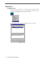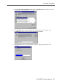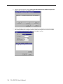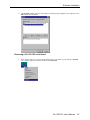
1
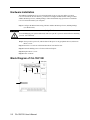
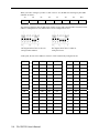
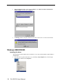
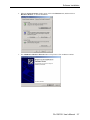
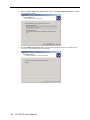
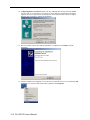
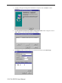
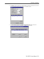
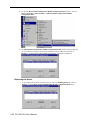
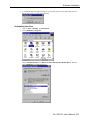
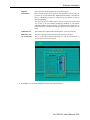
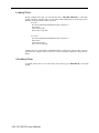
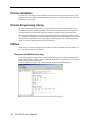
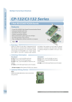
CA-132/132I User’s Manual Second Edition, May 2004 CA-132/132I User’s Manual The software described in this manual is furnished under a license agreement and may be used only in accordance with the terms of that agreement. Copyright Notice Copyright 2004 Moxa Technologies Co., Ltd. All rights reserved. Reproduction without permission is prohibited. Trademarks MOXA is a registered trademark of Moxa Technologies Co., Ltd. All other trademarks or registered marks in this manual belong to their respective manufacturers. Disclaimer Information in this document is subject to change without notice and does not represent a commitment on the part of Moxa. Moxa provides this document “as is,” without warranty of any kind, either expressed or implied, including, but not limited to, its particular purpose. Moxa reserves the right to make improvements and/or changes to this manual, or to the products and/or the programs described in this manual, at any time. Information provided in this manual is intended to be accurate and reliable. However, Moxa Technologies assumes no responsibility for its use, or for any infringements on the rights of third parties that may result from its use. This product might include unintentional technical or typographical errors. Changes are periodically made to the information herein to correct such errors, and these changes are incorporated into new editions of the publication. Table of Contents Chapter 1 Introduction ......................................................................................1-1 Overview..................................................... 1-2 Package Checklist............................................ 1-2 Product Features............................................. 1-2 Product Specifications ....................................... 1-2 Chapter 2 Hardware Installation.......................................................................2-1 Hardware Installation........................................ 2-2 Block Diagram of CA-132/132I ................................. 2-2 RS-422/485 Interface Settings ................................ 2-3 I/O Base Address & Interrupt Vector Settings ................. 2-3 IRQ Setting.................................................. 2-5 Initial Inspection........................................... 2-5 RS-422/485 Pin Assignments ................................... 2-5 Chapter 3 Software Installation ........................................................................3-1 Windows NT................................................... 3-2 Windows 2000/XP/2003......................................... 3-6 Windows 95/98/ME............................................ 3-16 DOS......................................................... 3-22 Chapter 4 Serial Programming Tool ................................................................4-1 PComm Installation........................................... 4-2 PComm Programming Library .................................... 4-2 Utilities.................................................... 4-2 RS-485 Programming.......................... 錯誤! 尚未定義書籤。 By RTS Mode (For back-compatibility) ........ 錯誤! 尚未定義書籤。 Appendix A Service Information ........................................................................ A-1 MOXA Internet Services ....................................... A-2 Problem Report Form.......................................... A-3 Product Return Procedure ..................................... A-4 1 Chapter 1 Introduction Welcome to MOXA CA-132/132I Series of advanced 2-port RS-422/485 PC/104 communication modules, a new industrial multiport serial board solution. Both ports of CA-132/132I can be configured by DIP Switch for either the RS-422 or RS-485 interface, and with its PC/104 standard, the CA-132/132I Series is compatible with any PC/104 CPU module or CPU card that accepts PC/104 expansion modules. The following topics are covered in this chapter: Overview Package Checklist Product Features Product Specifications Overview CA-132/132I is a PC/104 module that supports the RS-422/485 serial interfaces, and can be used with PC/104 CPU modules or CPU cards that accept PC/104 expansion modules. CA-132/132I has two independent serial interfaces, which are accessed through RJ45 connectors. You can configure both ports for the RS-422 or RS-485 interfaces by DIP switch. The module’s industry-standard MOXA UART (16C550 compatible) is fully programmable. Moxa has implemented its patented ADDC™ technology for RS-485 automatic direction control, so there is no need to change jumpers to switch the module between driver and receiver. The built-in 16 KV ESD surge protection protects other devices connected to the RS-485 network. Package Checklist MOXA CA-132/132I products are shipped with the following items: 1 MOXA CA-132/132I 2-port serial board CA-132/132I Document & Software CD CA-132/132I Quick Installation Guide NOTE: Notify your sales representative if any of the above items is missing or damaged. Product Features CA-132/132I Series products enjoy the following features: 2 RS-422/485 ports RS-422/485 communication distance up to 4000 feet (1.2 km) High speed data transmission rate up to 230.4 Kbps Switch selectable for I/O and INT Vector addresses (from Hex 000 to 3FF) 64-byte FIFOs IRQ settings are selectable by jumper Built-in 16 KV ESD surge protection for TX and RX lines 4 LED indicators onboard (red for TX, and green for RX) Support 4-wire RS-422 and 2/4-wire RS-485 ADDC™ for RS-485 transmission CA-132I has 2 KV isolation protection Product Specifications CA-132/132I Series boards have the following specifications: Dimensions: 9.6 cm × 9.0 cm Bus: PC/104 Baud rate: 50 to 230.4 Kbps Character length: 5, 6, 7, or 8 bits Parity: even, odd, none, mark, and space Stop bit: 1, 1.5 or 2 I/O connectors: dual 8-pin RJ-45 connectors Interrupt levels: IRQ 3, 4, 5, 6, 7, 9, 10, 11, 12 or 15 Clock input: 14.745 MHz Power consumption (+5 V): CA-132/210 mA, CA-132I/455 mA MTBF: 100,000 hrs @ 25℃ environment 1-2 CA-132/132I User’s Manual Introduction Operating temperature: 0 to 55℃ Storage temperature: -20 to 85℃ Relative humidity: 5 to 95%, non-condensing Regulatory Approvals: FCC Class A, CE CA-132/132I User’s Manual 1-3 1-4 CA-132/132I User’s Manual 2 Chapter 2 Hardware Installation This chapter includes information about hardware installation of CA-132/132I Series boards. The following topics are covered: Hardware Installation Block Diagram of CA-132/132I RS-422/485 Interface Settings I/O Address & Interrupt Vector Settings IRQ Setting Initial Inspection RS-422/485 pin assignments Hardware Installation The hardware installation of CA-132/132I serial boards is easy to carry out. Before you insert CA-132/132I into the PC/104 interface, you must first configure the RS-422/485 setting, I/O Base Address & Interrupt Vector, and IRQ Settings. Follow the detailed steps given below to install the CA-132/132I serial board in your computer. Step 1: Configure the RS-422/485 setting, I/O Base Address & Interrupt Vector, and IRQ Settings (see details below). Safety First! To avoid damaging your system and boards, make sure your PC’s power is turned off before installing your CA-132/132I board. Step 2: Turn your PC’s power off, and also shut off the power to any peripheral devices, and remove the PC’s cover. Step 3: Insert the CA-132/132I serial board into the PC/104 interface slot. Step 4: Fasten the holding screw to fix the serial board in place. Step 5: Replace the PC’s cover. Step 6: Power on the PC. Block Diagram of CA-132/132I SW4 (P2) SW1 Port 2 SW2 SW3 (P1) JP5 2-2 CA-132/132I User’s Manual Port 1 Hardware Installation RS-422/485 Interface Settings You can use DIP switches SW3 and SW4 to configure each port individually for either RS-422 (4-wire) or RS-485 (2/4-wire) interface with termination resistor(TR) on/off (120 ohm). SW3 configures Port 1, and SW4 configures Port 2, as shown in the switch setting diagrams below. SW3 (P1) SW4 (P2) The following diagram shows how to use the DIP switches to configure each port for either RS-422 (4-wire) or RS-485 (2/4-wire) interface with or without termination resistor. I/O Base Address & Interrupt Vector Settings CA-132/132I Series have two 7-switch DIP switch panels, named SW1 and SW2. Panel SW1 is for I/O Base Address setting, and SW2 is for Interrupt Vector setting. Once you configure Port 1’s I/O Base Address and Interrupt Vector, the settings for the other ports will be configured automatically as well. You can choose base addresses from hex 000 to 3FF. The default settings are CH#1 (Hex 180) for I/O Base Address and 1C0 for Interrupt Vector settings. Example: When you wish to configure your Port 1’s I/O base address to 180, the DIP switch settings of panel SW1 should be as follows: A3 A4 A5 A6 A7 A8 A9 Hex On On On On Off Off On 0 × 180 CA-132/132I User’s Manual 2-3 When you wish to configure your Port 1’s INT Vector to 1C0, the DIP switch settings of panel SW2 should be as follows: A3 A4 A5 A6 A7 A8 A9 Hex On On On Off Off Off On 0 × 1C0 The following diagrams show the DIP switch settings of panel SW1 and panel SW2 when the I/O base address is configured to be 180, and the INT Vector is configured to be 1C0. The diagram shown above is SW1 for setting I/O Base Address. The diagram shown above is SW2 for setting INT Vector. At this point, the start of I/O addresses of Port 2 will be automatically configured at 188. 2-4 A3 A4 A5 A6 A7 A8 A9 8 1 2 4 8 1 2 Hex On On On On On On On 0×000 On On On On On On Off 0×200 On On On On On Off Off 0×300 On On On On Off Off Off 0×380 On On On Off Off Off Off 0×3C0 On On Off Off Off Off Off 0×3E0 On Off Off Off Off Off On 0×3F0 Off Off Off Off Off Off Off 0×3F8 Off On On On On On On 0×008 Off Off On On On On On 0×018 Off Off Off On On On On 0×038 Off Off Off Off On On On 0×078 Off Off Off Off Off On On 0×0F8 Off Off Off Off Off Off On 0×2F8 CA-132/132I User’s Manual Hardware Installation IRQ Setting CA-132/132I Series has a jumper selectable(JP5) function for you to configure IRQ settings. Before you insert a CA-132/132I board into the PC/104 interface, you need to choose an available jumper from 3, 4, 5, 6, 7, 9, 10, 11, 12, or 15 to configure the IRQ setting. Initial Inspection Before we ship CA-132/132I products, we first perform a careful mechanical and electrical inspection of these serial boards. Products should be free of any marks or scratches and in perfect electrical order when customers receive them. Handle these boards only by their edges, since the static charge from your body may damage the integrated circuits. Always keep the boards in their anti-static package whenever they are not installed. You can also use this package to return the board should it need to be repaired. RS-422/485 Pin Assignments Async Port 4-wire RS-422/485 Pin Assignment (RJ45) PIN SIGNAL 1 X 2 X 3 TXD+ 4 TXD- 5 RXD- 6 RXD+ 7 GND 8 X Async Port 2-wire RS-485 Pin Assignment (RJ45) PIN SIGNAL 1 X 2 X 3 X 4 X 5 DATA- 6 DATA+ 7 GND 8 X CA-132/132I User’s Manual 2-5 3 Chapter 3 Software Installation After installing the CA-132/132I serial boards in your computer, the next step is to install the software. The drivers for CA-132/132I support various operating systems, including Window NT, Windows 2000/XP/2003, Windows 95/98/Me, and DOS. This chapter includes information about how to install and remove the CA-132/132I board. The following topics are covered in this chapter: Windows NT Windows 2000/XP/2003 Windows 95/98/Me DOS Windows NT Installing the driver The following procedure is for installing the CA-132/132I serial board driver under Windows NT 4.0. 3-2 1. Use the mouse to position the cursor over your desktop’s Network icon, and then click the right mouse button. Select Properties and then click the left mouse button. 2. When the Network window opens, click on the Adapters tab and then click on Add. CA-132/132I User’s Manual Software Installation 3. When the Select Network Adapter window opens, click on Have Disk to install the driver from the floppy disk enclosed with the CA-132/132I serial board. 4. The Insert Disk window will open asking you to insert the disk into your computer. Type A:\windows.nt to locate the setup file on the disk and then click OK. 5. The Setup window will open, showing that the computer is copying the setup file to your computer. CA-132/132I User’s Manual 3-3 3-4 6. After the setup file has been copied, the Moxa PC104 Communication Module Configuration Panel window will open. Click Add to continue. 7. When the Property window opens, select CA132 Series or CA132I Series under Board Type. The window will show the COM port number to which the serial ports of CA-132/CA-132I are assigned, and the default settings for the ports. Click OK to continue. CA-132/132I User’s Manual Software Installation 8. The Network window will open, showing the serial board you just added to your computer. Click OK to finish the installation. Removing a CA-132/132I serial board 1. If you wish to remove a CA-132/132I serial board, move your mouse to your desktop’s Network icon, click the right mouse button, and then select Properties. CA-132/132I User’s Manual 3-5 2. When the Network window opens, choose Adapters, select MOXA PC104 Communication Module Adapter, and then click on Remove. 3. A Warning window will open. Click Yes if you wish to remove the CA-132/132I serial board. Windows 2000/XP/2003 Installing the driver The following procedure explains how to install the CA-132/132I serial board driver under Windows 2000/XP/2003. 1. 3-6 Use your mouse to position the cursor over your desktop’s My Computer icon, click the right mouse button, and then select Properties. CA-132/132I User’s Manual Software Installation 2. When the System Properties window opens, click on the Hardware tab, and then click on Hardware Wizard… to start the installation. 3. The Add/Remove Hardware Wizard window will open next. Click on Next to continue. CA-132/132I User’s Manual 3-7 3-8 4. When the Choose a Hardware Task window opens, select Add/Troubleshoot a device, and then click on Next to continue. 5. The New Hardware Detection window will open showing that the Wizard is searching for the CA-132/CA-132I serial board on your computer. CA-132/132I User’s Manual Software Installation 6. When the Choose a Hardware Device window opens, select Add a new device and then click Next to continue. 7. The Find New Hardware window will open next. Select No, I want to select the hardware from a list, since CA-132/132I is a brand new type of ISA serial board, and then click on Next to continue. CA-132/132I User’s Manual 3-9 8. When the Hardware Type window opens, select Multi-port serial adapters under Hardware types, and then click on Next to continue. 9. When the Select a Device Driver window opens, click on Have Disk to install the CA-132/132I driver from the floppy disk that came with the CA-132/132I serial board. 10. The Install from Disk window that opens will prompt you to insert the installation disk into your computer’s floppy disk drive. 3-10 CA-132/132I User’s Manual Software Installation 11. After inserting the installation disk, click on Browse to locate the setup file from the disk. Click OK to continue. 12. When the Select a Device Driver window opens, select MOXA CA132 Series or MOXA CA132I Series and then click Next to continue. 13. The Start Hardware Installation window will open next. Click on Next to continue. CA-132/132I User’s Manual 3-11 14. A Digital Signature Not Found window will open. Although this message states that MOXA CA132 Series (or CA132I Series if you choose it) driver does not contain a Microsoft digital signature, the CA132 Series driver has already been tested and been shown that it can support Windows OS. Click Yes to continue the installation. 15. The next window to open states that the installation is completed. Click Finish to end the installation. 16. After the installation is completed, use your mouse to position the cursor over your desktop’s My Computer icon, click the right mouse button, and then select Properties. 3-12 CA-132/132I User’s Manual Software Installation 17. When the System Properties window opens, click on the Hardware tab, and then click on Device Manager. 18. The Device Manager window will open next. At this point, you should be able to find MOXA CA132 Series/MOXA CA132I Series under Multi-port serial adapters, and MOXA communication Port 1 and Port 2 (assigned to COM 15 and COM 16, respectively, for the example shown here) under Ports (COM & LPT). CA-132/132I User’s Manual 3-13 19. Select MOXA CA132 Series/MOXA CA132I Series, click the right mouse button, and then select Properties. 20. The MOXA CA132 Series/MOXA CA132I Series Properties window will open, allowing you to view general information, Ports Configuration, Driver version, and Resource Settings. 3-14 CA-132/132I User’s Manual Software Installation Disabling the device 1. Use your mouse to position the cursor over you desktop’s My Computer icon, click the right mouse button, and then select Properties. 2. The System Properties window will open. Choose Hardware and select Device Manager. CA-132/132I User’s Manual 3-15 3. The Device Manager window will open. Select MOXA CA132 Series/MOXA CA132I Series under Multi-port serial adapters, and click on the right mouse button. Select Disable and click on the left mouse button to disable the device. Uninstalling the device 1. 2. 3. Follow steps 1 and 2 of Disabling the device. Select MOXA CA132 Series/MOXA CA132I Series under Multi-port serial adapters, click the right mouse button, and then select Uninstall. A Warning window will open. Click OK to uninstall the device. Windows 95/98/ME Installing the driver The following is for installing the driver of CA-132/132I serial boards under Windows 95/98/ME. 1. Insert the installation disk into your computer. Click on Run under the Start Menu, and then click on Browse to locate the setup file in the disk, or directly type in the path. 3-16 CA-132/132I User’s Manual Software Installation 2. A Welcome message will appear. Click Next to continue. 3. A window will open stating the computer is ready to install the driver. Click on Next to continue. 4. A message will appear showing that the setup file is being installed. CA-132/132I User’s Manual 3-17 5. A window will appear showing that the installation is completed. Click on Finish to end the installation. 6. The Moxa PC104 Communication Module Configuration Panel window will appear. Click on Add to add the CA-132/132I serial board to your computer. 7. The Property window will open. Select CA132 Series/CA132I Series under Board Type. 3-18 CA-132/132I User’s Manual Software Installation 8. The Property window will show the COM port number to which the serial ports of CA-132/132I are assigned, and the default settings of the ports. Click OK to continue. 9. The Moxa PC104 Communication Module Configuration Panel window will show the CA132/CA132I serial board you just added. Click OK to close the window. CA-132/132I User’s Manual 3-19 10. To open the Moxa PC104 Communication Module Configuration Panel window , click on Start Programs Moxa Untilities MOXA PC104 Communication Module Configuration Panel. 11. The Moxa PC104 Communication Module Configuration Panel window will open allowing you to see the CA132 Series/CA132I Series serial board you just added. You can click on Property to see and configure the information and settings of the board’s COM ports. Removing the device 1. If you wish to remove the device, follow steps 11 and 12 of Installing the driver. Click on Remove when the Moxa PC104 Communication Module Configuration Panel opens. 3-20 CA-132/132I User’s Manual Software Installation 2. A warning message will appear asking you if you really want to remove this board. Click on Yes to remove the CA-132/132I serial board. Uninstalling the driver 1. 2. Click on Start Settings Control Panel. Select Add/Remove Programs. Choose Install/Uninstall, select MOXA PC104 Communication Module Driver, and then click Add/Remove to uninstall the driver. CA-132/132I User’s Manual 3-21 3. A message will appear asking you if you really want to remove the driver. Click Yes to uninstall the driver. 4. A message will prompt up confirming that the uninstallation of the driver is completed. Click OK to close the window. DOS MOXA DOS API-232 is a software package that assists users to develop and/or debug programs for serial communications. This section will show you how to install the package, how to setup up the driver, and how to load or unload driver. For details of the serial programming (API-232 Library) and utilities, please refer to the next chapter, “Serial Programming Tools”. Installing Driver Run the installation program, DOSINST.EXE, in the DOS folder. Specify the target API-232 directory (e.g. C:\MOXA) where software driver will be copied. Press F2 to start the installation. 3-22 CA-132/132I User’s Manual Software Installation After installation is complete, you will be prompted to proceed running setup program. It is strongly recommended to do so. Driver Setup The following are steps for setting up the CA-132 Series(CA-132/CA-132I) driver. Note that it is not intended to illustrate all the convenient functions of the setup programs when configuring the boards. Please refer to the F1 on-line help instructions as running setup program. 1. Run the setup program, BIN\SETUP.EXE. 2. Please press Enter to select the proper model name, CA-132 Series. If you install CA-132I model, select CA-132I Series. CA-132/132I User’s Manual 3-23 3. You have to configure the Port No., I/O Address, IRQ and INT Vector properly. These settings MUST match up the hardware configuration of CA-132 or CA-132I. 4. You may press PgDn key to have advanced “Port setup”. Now the configuration of the desired CA-132 Series board will be shown along with other default settings, such as port number, buffer size, etc. Note ! Up to now you have completed the setup for CA-132 Series board. You may skip this step and go directly to the next step 4 if you need not change any setting or configure any board. You may now enter/modify each port’s configuration. These displayed values are the port initial values as driver is loaded. 3-24 CA-132/132I User’s Manual Software Installation Legend: Some noticeable fields and functions are explained below. Port number: This is actually the port ID of each port. The application software will refer to the port by its port number (ID). Duplicated port number is not allowed. That is, each MOXA serial port is referred to as port number in terms of serial programming. You may map the port number range to the one you prefer between 0 and 127 as long as no port number overlapping condition or port number undefined condition occurs. Generally, you should take the convenience of programming into consideration when specifying the port numbers for the board. TxD buffer size: The transmission (output) buffer allocated in the system for each port. RxD buffer size: The receiving (input) buffer allocated in the system for each port. F5: Group Edit: This is a convenient function that helps you edit the configuration of several ports at one time as a group. 5. Press F10 to save the latest configuration and exit the SETUP program. CA-132/132I User’s Manual 3-25 Loading Driver Having completed the setup, you can load the driver, “BIN\DPC-DRV.EXE”, at the DOS prompt. The driver will detect the CA-132 Series board automatically. If the board(s) is(are) detected, a message similar to below will show: (CA-132) PC/104 Communication Module DOS driver Version 1.0 Setup driver … CA-132 series OK! Device driver setup O.K. (CA-132I) PC/104 Communication Module DOS driver Version 1.0 Setup driver … CA-132I series OK! Device driver setup O.K. It means the CA-132 Series driver is installed properly. At this point, you are ready to execute application that supports API-232 functions, or start developing applications using API-232 library. Unloading Driver To unload (release) the CA-132 Series driver from memory, type “DPC-DRV/Q” at the DOS prompt. 3-26 CA-132/132I User’s Manual 4 Chapter 4 Serial Programming Tool Moxa supports a class of easy to use, yet powerful serial programming libraries and communication troubleshooting utilities under Windows NT/2000/XP/2003 and Windows 95/98/Me. Use these MOXA Serial Programming Tools to decrease your software development time. In the following sections, we describe the installation of the library, and the utilities supported for various programming platforms. PComm, a professional serial comm tool for PCs, is a software package that runs under Windows NT/2000/XP/2003 and Windows 95/98/Me. PComm provides: A powerful serial communication library for easy programming in the most popular programming languages. The serial communication library is useful for developing applications for data communications, remote access, data acquisition, and industrial control under Windows NT/2000/XP/2003 or Windows 95/98/Me. It is a simpler solution compared to the more complex Windows Win32 COMM API. Useful utilities such as diagnostic, monitor, and terminal emulator. Illustrative sample programs, Comprehensive on-line documentation. The following topics are covered in this chapter: PComm Installation PComm Programming Library Utilities PComm Installation To install PComm, run \Setup.exe from the diskette enclosed in the package. Please note that the PComm diagnostic and monitor utilities are for MOXA boards only; these two utilities will not work with other manufacturer’s serial boards. PComm Programming Library The serial communication library assists you in developing serial communications programs for any COM port that complies with Microsoft Win32 API. It facilitates the implementation of multi-process and multi-thread serial communication programs and hence remarkably reduces development time. This serial communication library provides a complete function library and sample programs for Visual C++, Visual Basic, and Delphi. To view detailed function descriptions and sample programs, click on [Start] [Program] [PComm Lite] [PComm Lib Help], [PComm Porting Notes] or [PComm Programming Guide], or refer to the sample programs in the PComm directory. Utilities In this section, we give brief descriptions of each utility. For more information about these utilities, see the on-line help from the software diskette. Diagnostic (for MOXA boards only) A convenient diagnostic program, ONLY for MOXA boards and ports, provides internal and external testing of IRQ, TxD/RxD, UART, CTS/RTS, DTR/DSR, DTR/DCD, etc. It allows the user to check the function of both software and hardware. To run the Diagnostic program, click on [Start] [Program] [PComm Lite] [Diagnostic]. 4-2 CA-132/132I User’s Manual Serial Programming Tool Monitor (for MOXA boards under Windows NT Only) A useful port status monitoring program allows you to monitor data transmission of selected MOXA COM ports. It monitors data transmission/receiving throughput, and communication line status, with data updated and displayed on the screen at regular time intervals. Click on a specific port to see a graph of the current communication parameters and status of that port. To run the Monitor program, click on [Start] [Program] [PComm Lite] [Monitor]. Terminal Emulator Terminal Emulator can be used to connect to various ports to see if data transmission is functioning correctly. Terminal Emulator features multi-windows, and supports VT100 and ANSI terminal types. You can transfer data interactively, send patterns periodically, and transfer files using ASCII, XMODEM, YMODEM, ZMODEM, and KERMIT protocols. To run Terminal Emulator, click on [Start] [Program] [PComm Lite] [Terminal Emulator]. CA-132/132I User’s Manual 4-3 4-4 CA-132/132I User’s Manual A Appendix A Service Information This appendix shows you how to contact Moxa for information about this and other products, and how to report problems. In this appendix, we cover the following topics. MOXA Internet Services Problem Report Form Product Return Procedure MOXA Internet Services Customer satisfaction is our number one concern, and to ensure that customers receive the full benefit of our products, Moxa Internet Services has been set up to provide technical support, driver updates, product information, and user’s manual updates. The following services are provided E-mail for technical support ............................... [email protected] World Wide Web (WWW) Site for product information: ............................ http://www.moxa.com A-2 CA-132/132I User’s Manual Service Information Problem Report Form MOXA CA-132/132I Series Customer name: Company: Tel: Fax: Email: Date: 1. Moxa Product: 2. Serial Number: CA-132 CA-132I _________________ Problem Description: Please describe the symptoms of the problem as clearly as possible, including any error messages you see. A clearly written description of the problem will allow us to reproduce the symptoms, and expedite the repair of your product. CA-132/132I User’s Manual A-3 Product Return Procedure For product repair, exchange, or refund, the customer must: Provide evidence of original purchase. Obtain a Product Return Agreement (PRA) from the sales representative or dealer. Fill out the Problem Report Form (PRF). Include as much detail as possible for a shorter product repair time. Carefully pack the product in an anti-static package, and send it, pre-paid, to the dealer. The PRA should be visible on the outside of the package, and include a description of the problem, along with the return address and telephone number of a technical contact. A-4 CA-132/132I User’s Manual