1
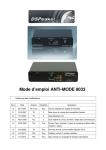
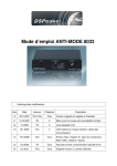
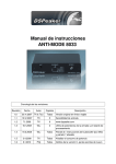
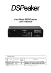
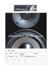
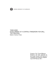
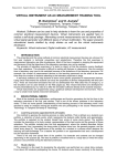
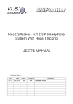
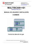
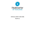
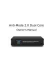
ANTIMODE 8033 User's Manual Revision History Rev. Date Author Affected chapters Description 1.0 30.11.2007 TK & ToLi All Original version Finnish and English 1.1 13.12.2007 TK 5 Updated input sensitivity level 1.2 7.1.2008 TK 6 www.dspeaker.com 1.3 18.1.2008 ToLi 2 Input level warning leds / converter delay 1.4 19.3.2008 ToLi All Typo fixes, chapter 2.1 reflex advice added, chapter 7 added 1.5 3.4.2008 TK All Reformatted, added power consumption to Ch 8. 1.6 8.1.2010 POj All Cversion graphics, some parts rewritten 1.7 9.11.2010 POj All S version added, recycling and other information added ANTIMODE 8033 Recycling information The product you have purchased is marked according to the Waste Electrical and Electronic Equipment Directive (WEEE Directive). There are takeback systems in place that help to preserve nature and natural resources when products are disposed of appropriately. If you need to dispose of this product, use the takeback system that has dedicated collection facilities for electronic equipment. Do not put the product into household waste disposal! Also, the product has been manufactured using parts and processes that follow the directive of the Restriction of the use of certain Hazardous Substances in Electrical and Electronic Equipment (RoHS). Rev. 1.7 10.11.2010 Page 2 (12) ANTIMODE 8033 Table of contents 1. Connections and buttons.......................................................................................4 1.1. Front panel:.........................................................................................................4 1.2. Back Panel.........................................................................................................5 2. Quick setup guide...................................................................................................6 2.1. Before calibration................................................................................................6 2.2. Calibration..........................................................................................................7 2.3. After calibration..................................................................................................7 3. Wider area correction.............................................................................................8 3.1. Strategy 1, “Compensation of the weakest point”:.............................................8 3.2. Strategy 2, “Gradient compensation”:................................................................9 4. Basic operation......................................................................................................10 4.1. Bypass mode....................................................................................................10 4.2. Lifting EQ..........................................................................................................10 4.2.1. “Flat”................................................................................................................10 4.2.2. Lifting 1525Hz................................................................................................10 4.2.3. Lifting 2535Hz................................................................................................10 4.3. Bridging.............................................................................................................11 4.4. ADC level warning............................................................................................11 4.5. Powering Up and Down....................................................................................11 5. Technical specification.........................................................................................12 6. Manufacturer..........................................................................................................12 7. Support...................................................................................................................12 Rev. 1.7 10.11.2010 Page 3 (12) ANTIMODE 8033 ANTIMODE 8033 User's Manual 1. Connections and buttons 1.1. Front panel: Figure 1: ANTIMODE 8033C Front panel 1. 2. 3. 4. 5. 6. 7. 8. Microphone input jack Button A: LIFT 25 / LIFT 35 / FLAT selector Short press: Selects low frequency boost Long press: Store current low frequency boost setting Button B: BYPASS Short press: Disable/enable processing Long press: Begin secondphase calibration for wide area correction Buttons A & B simultaneously long press: Begin calibration PWR LED: Lit when the device is on BYPASS LED: Lit when bypassed LIFT 25 LED: Lit when 1525Hz lifting EQ and subsonic filter is on LIFT 35 LED: Lit when 2535Hz lifting EQ and subsonic filter is on POWER switch: Switches power on/off (in AntiMode 8033C) Figure 2: ANTIMODE 8033S Front panel Rev. 1.7 10.11.2010 Page 4 (12) ANTIMODE 8033 1.2. Back Panel AntiMode 8033C Figure 3: ANTIMODE 8033C rear panel 1. 2. 3. 9V AC connector: Input power. Note: AntiMode 8033C needs AC voltage! OUT 0connector: Inphase RCA out (default) OUT 180connector: Outofphase RCA out OUT0 and OUT180 connectors can be used for bridged operation of stereo amplifier LINE INconnector: Line input (subwoofer preout signal from preamplifier or A/V receiver) 4. AntiMode 8033S Figure 4: ANTIMODE 8033S rear panel 1. 2. 3. 4. 5. Rev. 1.7 9V AC / 12V DC connector: Input power. OUT 180 connector: Outofphase RCA out OUT 0 connector: Inphase RCA out (default) OUT0 and OUT180 connectors can be used for bridged operation of stereo amplifier or create balanced XLR output with an adapter cable LEFT LINE IN connector: Line input (subwoofer preout signal from pre amplifier or A/V receiver) RIGHT LINE IN connector: Line input (subwoofer preout signal from pre amplifier or A/V receiver) The dual LEFT / RIGHT inputs can be used to connect stereo systems that have only stereo preamplifier outputs instead of a single LFE output. You can also connect your home theater LFE output to the LEFT input and stereo system to the RIGHT input using the stereo to mono summing cable. 10.11.2010 Page 5 (12) ANTIMODE 8033 2. Quick setup guide 1. Connect the subwoofer signal preout to "LINE IN" (LEFT input in 8033S). 2. Connect the active subwoofer to "OUT 0" output. 3. Connect microphone plug to "MIC" jack and fix the microphone as close to the listening position (head of the listener) as possible. 4. Connect the power supply to "9V AC" connector and wall socket. 5. Switch ANTIMODE 8033 on (AntiMode 8033S will turn on automatically when you plug it in). Note: All the leds on front panel are lit if the device has never been calibrated 6. Switch on the subwoofer and leave its volume setting unaltered Figure 5: Setting up ANTIMODE 8033 2.1. Before calibration With small reflex subwoofers, it is adviced to decrease their volume before calibration. If the subwoofer has a builtin lowpass or other type of filter, it should be deactivated during calibration process. It can be reactivated after calibration. Cross over and lowpass filters at the A/V receiver do not affect calibration, since they take place before AntiMode 8033 in the signal chain. Also any other audio equipment that may affect subwoofer signal prior to the AntiMode 8033 do not interfere with the calibration process. As room modes may have strong dependency of the position, it is advisable to also pay attention to the vertical positioning (height) of the calibration microphone. The microphone is omnidirectional, so its precise orientation doesn't matter. If you want the room correction to affect a wider area, the first calibration point should be selected near the center of this area (or the primary listening position). More about wider area correction in the latter section “Wider area correction”. Rev. 1.7 10.11.2010 Page 6 (12) ANTIMODE 8033 2.2. Calibration Press both buttons at the front panel and hold them for about three seconds. Make sure that both of the buttons are pressed and held. After about three seconds the middle LED will start flashing and calibration begins. You may now release the buttons and wait for the automatic calibration to finish. The measurement program analyzes the room four times with a frequency sweep. During the calibration, the device will adjust the output level automatically. If the microphone level in is too loud, it is automatically decreased. The calibration is quite robust, so it tolerates certain amount of background noise, hence speech and small noises do not distract the process. However, one should avoid making loud noises, especially near the microphone. If you initiate calibration by mistake, you can abort it by turning off the unit (Anti Mode 8033C), or by pressing either button after a few seconds of calibration (Anti Mode 8033S). 2.3. After calibration Once the last sweep is over, the calibration is finished. The results are stored in the nonvolatile memory inside the unit, so they are not lost even when AntiMode loses power. The AntiMode 8033 is now fully functional and the microphone can be detached, unless the user wishes to perform wider area calibration. After calibration the subwoofer may sound more quiet than before. This is because the room resonances have been suppressed. Typically, the subwoofer volume needs to be increased slightly (310 dB). If the A/V receiver supports speaker distances, you can add 90 cm to the subwoofer distance relative to other speakers to compensate for the internal processing delay. This is not absolutely necessary since the delay is small enough that the human auditory system can generally not detect it. You can also use your A/V receiver's automatic functions to determine the correct distance and level settings. In that case the processing latency of AntiMode is automatically taken into account by the A/V receiver. The speaker setting “small” should be used for best results. Attention! If for some reason only one sweep signal was generated during the calibration, both buttons at the front panel were not pressed. In this case, the calibration process must be reinitialized. Whenever the placement of the subwoofer or listening position changes, the calibration should be performed again to assure optimal result. Rev. 1.7 10.11.2010 Page 7 (12) ANTIMODE 8033 3. Wider area correction In some situations it is more favourable to compensate the room acoustics for a larger area. In this case, the result is no longer optimal in any single listening position, but generally improved for a wider area. Before wider area correction, the normal calibration procedure described in the earlier section must be performed. The initial calibration is done with the microphone at the center of the listening area (or primary listening position within the area). AntiMode 8033 is calibrated to larger area by taking the microphone to some other point within the listening area. Pressing and holding button B, bypass (Figure 1, object 3) will initiate a single additional frequency sweep. AntiMode 8033 will use it in conjunction with the data gathered at the first calibration to create a compensation model for a larger listening area within the room. Do not accidentally press and keep both buttons at the front panel, as this will start main calibration all over again and overrides the current room data. Wider area calibration can be done multiple times and it does not lose the data from the main calibration. Thus it is easy to try different second phase calibration points for the best audible result. There are several strategies in choosing the microphone position for second phase calibration. 3.1. Strategy 1, “Compensation of the weakest point”: When the first (main) calibration is performed to the primary listening position or to the center of the listening area, one can already evaluate the result by listening it at different positions. If the result is not adequate at some location, this spot could be used as a second phase calibration point. Also any location between this point and the first point can lead to good results. Inevitably, the result will get less optimal in the first point, but usually improved a lot everywhere else including the weakest point. Rev. 1.7 10.11.2010 Page 8 (12) ANTIMODE 8033 3.2. Strategy 2, “Gradient compensation”: When the first (main) calibration is performed to the primary listening position or to the center of the listening area, but it is difficult to find the weakest point within the listening area, gradient compensation is a good approach. Second phase calibration point for wider area correction can be found by taking the microphone from first calibration point toward the closest corner of the listening room by 4090 cm and down (toward the floor) approximately 1020 cm. Wider area calibration second phase will be performed to this achieved position. If the first (main) calibration point was in close proximity of walls (distance less than 1m.) , the microphone should be moved only about 2040 cm toward that wall for second phase calibration. Gradient compensation method usually works well in removing the axial modes for larger area in rectangular room. Rev. 1.7 10.11.2010 Page 9 (12) ANTIMODE 8033 4. Basic operation 4.1. Bypass mode If you want to compare the corrected and uncorrected operation, press the Bypass button shortly. This will switch between bypass and normal mode. The first press will put AntiMode into bypass mode, which is also indicated by the “Bypass” LED (Figure 1, object 5) on. If the Bypass mode is already active, the unit switches to normal mode instead. In bypass mode, no room corrections are active. Also the user selected lifting EQ is turned off. 4.2. Lifting EQ The Lifting EQ button rotates between three equalization modes of AntiMode 8033 and stores the setting if held longer. A brief sound is heard from subwoofer when the setting is stored. 4.2.1. “Flat” The first lifting EQ setting is no lifting, “flat.” Neither of the LEDs 'LIFT 25' nor 'LIFT 35' is lit. In this setting, the target response is flat from 5 to 148 Hz. 4.2.2. Lifting 1525Hz In lifting 1525 mode, when the LED “LIFT 25” is lit, the AntiMode will boost frequencies between 15 and 25 Hz (max. 7dB at 20Hz). This will also activate digital infasonic filter, which will filter out frequencies below 10Hz, that can be dangerous to ported subs without proper protection. 4.2.3. Lifting 2535Hz Third mode, lifting 2535 similarly boosts range 2535 Hz (max. 7dB at 30Hz) on subwoofer. This mode is active when the LED LIFT 35 is on. This will also activate digital infasonic filter, which will filter out frequencies below 10Hz. It is easiest to find out which of the lifting settings gives best result by simply listening. Lifting below 35Hz could be useful for reflex subwoofers, which have port tuning above 30Hz, but the lowest frequencies are attenuated to the listening position. With music, 'flat' is probably the best option, as it gives the most accurate transient response. Lifting below 25Hz could be applicable for a large subwoofer, which has 6dB point too high because of suboptimal positioning. Rev. 1.7 10.11.2010 Page 10 (12) ANTIMODE 8033 4.3. Bridging Bridging is always done with user's own responsibility and consideration, as not all stereo amplifiers can provide bridged operation. Ordinary stereo amplifier can be bridged by using both OUT0 and OUT180 RCA outputs. (Figure 2, objects 2 and 3.). Using differential output will give 2.83 times the amplification of a single output channel. In bridging + poles of both the output channels of the power amplifier are used instead of + and . Bridging is useful as means of multiplying the power of stereo amplifier used for passive subwoofer. 4.4. ADC level warning If the input signal level in ADconverter is close to the input sensitivity maximum value, the user is warned about this in two phases. If the input signal level has only 3 dB of headroom, the “Bypass” led will start flickering. If the input level reaches maximum, the “lift 25” led will start flashing (independent of whether these leds were lit in the first place or not). If the input signal is higher than maximum value of ADC, the signal is saturated to avoid clipping. The ADC level warning is useful in optimizing the input signal level that goes into AntiMode. The level warning is not active during calibration. During calibration the output level is decreased automatically if needed, and the flashing LED is used to indicate the progress of calibration. 4.5. Powering Up and Down AntiMode 8033C Turn on AntiMode from the power switch before your subwoofer and power down subwoofer before turning off AntiMode. Because AntiMode consumes very little power, you may also choose to leave it on permanently. AntiMode 8033S AntiMode 8033S has almost completely eliminated poweron and poweroff transients, so you can easily power it on and off using a switchable power cord or power output from your AudioVideo receiver. AntiMode also fades in the signal when it starts, so it can be powered on even while audio signal is already applied to the input connector(s). Rev. 1.7 10.11.2010 Page 11 (12) ANTIMODE 8033 5. Technical specification Electrical characteristics: Power consumption Input sensitivity: Amplification: Dynamic ratio (unweighted): 1.2 W (from 9V AC) Line level (max 1.75 Vrms) 8033C 8033S 9V AC 9V AC or 12 V DC 5 – 160 Hz 5 – 240 Hz Bessel 12 dB/octave, Q ~ 0.5 fc = 160Hz fc = 240 Hz 3.5 dB 3.0 dB 90 dB >92dB Firmware features: AntiModeFilters: Correction range: Frequency resolution: Maximum attenuation: Filter Qvalue range: Subsonicfilter: Computation accuracy: 24 pcs. 16 144 Hz < 0.5 Hz 96 dB Unlimited (32bit integer space) 10 Hz (user selectable) 32/40bit integer Operation voltage: Frequency range (3 dB): Lowpass: 6. Manufacturer VLSI Solution Oy / DSPeaker Division Hermiankatu 8 B FIN-33720 Tampere FINLAND Fax: +358-3-3140-8288 Tel: +358-3-3140-8200 Email: [email protected] URL: http://www.dspeaker.com/ 7. Support [email protected] [email protected] Rev. 1.7 10.11.2010 Page 12 (12)