1
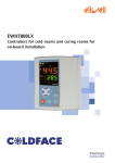
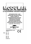
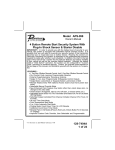
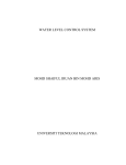
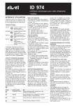
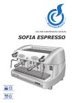
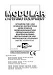
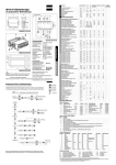
ENGLISH
EN
Electronic controllers for refrigeration units
EWPLUS 902/961
UP
KEYS
Press and release
Scrolls through menu items
Increases values
Press for at least 5 secs
Activates the Manual Defrost function
DOWN
Press and release
Scrolls through menu items
Decreases values
Press for at least 5 secs
Configurable function by user (par.H32)
EWPLUS 971/974
STAND-BY (ESC)
Press and release
Returns to the previous menu level
Confirm parameter value
Press for at least 5 secs
Activates the Stand-by function
(when outside the menus)
set
SET (ENTER)
Press and release
Displays alarms (if active)
Opens the Machine Status menu
Press for at least 5 secs
Opens the Programming menu
Confirms commands
LEDs
Reduced SET / Economy
Fan LED
Compressor LED
Aux LED
Flashing:
reduced set active
Quick flashing: access to level 2 parameters
Off:
otherwise
Permanently on: fans active
Off:
otherwise
(only EW Plus 971 and EW Plus 974)
Permanently on: compressor active
Flashing:
delay, protection or
blocked start-up
Off:
otherwise
Permanently on: Aux active*
*depending on model
(only EW Plus 971 and EW Plus 974)
Defrost LED
HEAT mode LED
Permanently on: defrost active
Flashing:
manual or D.I. activation
Off:
otherwise
°C LED
Permanently on: °C setting (dro = 0)
Off:
otherwise
°F LED
Permanently on: °F setting (dro = 1)
Off:
otherwise
Alarm LED
Permanently on: alarm on
Flashing:
alarm acknowledged
Off:
otherwise
Permanently on: compressor in HEAT mode
Off:
otherwise
(only EW Plus 902 and EW Plus 961)
NOTE:
If the instrument is set in the COOL mode, in order to
use it in the HEAT mode it is necessary to re-programme
the instrument by using the properly programmed
Copycard.
The same procedure should be followed to pass from
the HEAT mode to the COOL mode.
NOT USED
(only EW Plus 902 and EW Plus 961)
ACCESSING AND USING THE MENUS
Resources are organised into 2 menus which are accessed as explained below:
• ‘Machine Status’ menu: press and release the set key.
• ‘Programming’ menu: press for at least 5 secs the set key.
Either do not press any keys for 15 seconds (time-out) or press the
key once, to confirm the last value displayed
and return to the previous screen.
MACHINE STATUS MENU
Access the “Machine Status” menu by pressing and releasing the set key. If no alarms are active, the “SEt” label
appears. By pressing the
and
keys you can scroll all folders in the “Machine Status” menu:
- AL: alarms folder (only visible if an alarm is active);
set
- SEt: Set point setting folder;
- Pb1: probe 1 folder;
- Pb2: probe 2 folder **;
(** models EW Plus 971 and EW Plus 974 only)
Setting the Set point: To display the Set point value press the set key when the ‘SEt’ label is displayed.
The Set point value appears on the display. To change the Set point value, press the
and
keys within 15 seconds. Press set to confirm the modification.
set
set
set
Displaying the probes: When the Pb1 or Pb2* label is displayed, press set and the associated probe value will appear (* Pb2 is only present on models EW Plus 971 and EW Plus 974).
SET POINT EDIT LOCK
It is possible to disable the keypad on this device. The keypad can be locked by programming the ‘LOC’ parameter.
With the keypad locked you can still access the ‘Machine Status’ menu by pressing set to display the Set point,
but you cannot edit them. To disable the keypad lock, repeat the locking procedure.
PROGRAMMING MENU
To access the ‘Programming’ menu press for at least 5 secs the set key. If specified, the ‘PA1’ for the level 1
parameters and the ‘PA2’ for the level 2 parameters access PASSWORD will be requested (see Par. ‘PASSWORD’)
At the access, the display will show the first parameter (“diF”). By pressing the
and
keys you can scroll all
parameters in the current level:
set
5 secs
set
set
Select the desired parameter using the
and
keys. Press set to see the current value of the selected
parameter. Press
and
to change the value and then press set to save it.
NOTE: It is strongly recommended that you switch the device off and on again each time the parameter configuration
is changed, in order to prevent malfunctioning of the configuration and/or ongoing timings.
PASSWORD
‘PA1’ Password:
it allows to access to the level 1 parameters. In the standard configuration the password is disabled (value = 0). To enable
it (value ≠ 0) enter the “Programming” menu by pressing the
and
keys, scroll the parameters until “PS1” label
is displayed, press the set key to display the current value, change it by using the
and
keys and then press the
set key to save it. If the password is already enabled, you will be required to enter it to access the ‘Programming’ menu.
To enter it:
set
set
set
‘PA2’ Password:
it allows to access to the level 2 parameters. In the standard configuration the password is enabled (valore ≠ 0). To change
its value follow the steps like for ‘PA1’ and change the ‘PS2’ parameter value. The visibility of the ‘PA2’ label will be:
1) If PA1 and PA2 ≠ 0:By pressing the set key for more than 5 seconds, “PA1” and “PA2” labels will be displayed at the
same level and it will be possible to access either the level 1 or the level 2 parameters.
2) Otherwise:
The ‘PA2’ password is present between the level 1 parameters. If ‘PA2’ is enabled, you will be required to enter it to access the level 2. To enter it follow the steps described for the ‘PA1’ password
If the password is incorrect, the instruments display the PA1/PA2 label and you will have to repeat the entry procedure.
ALARMS
Label
Fault
Cause
Effects
Remedy
E1
Probe1 faulty
(cold room)
• reading of out of range operating
values
• probe faulty / short-circuited / open
• Display label E1
• Alarm icon permanently ON
• Min/max alarm regulator disabled
• Compressor operation according to “Ont”
and “OFt” parameters.
• check probe type (NTC)
• check the probe wiring
• replace probe
E2
Probe2 faulty
(defrost)
• reading of out of range operating
values
• probe faulty / short-circuited / open
• Display label E2
• Alarm icon permanently ON
• The defrost cycle will end due to Time out
(Parameter “dEt”)
• check probe type (NTC)
• check the probe wiring
• replace probe
AH1
Probe1 HIGH
Temperature
alarm
• value read by Pb1 > HAL after time
of “tAO”.
(see “MAX/MIN TEMP. ALARMS “)
• Registration AH1 label in the AL folder
• No effect on regulation
• Wait until temperature value read
by probe1 returns below HAL.
AL1
Probe1 LOW
Temperature
alarm
• value read by Pb1 < LAL after time
of “tAO”.
(see “MAX/MIN TEMP. ALARMS”)
• Registration AL1 label in the AL folder
• No effect on regulation
• Wait until temperature value read
by probe1 to come back obove LAL
EA
External alarm
• Digital input activated
(H11 = ±5)
• Registration EA label in the AL folder
• Alarm icon permanently ON
• Regulation blocked if EAL = y
• check and remove the external
cause which generate alarm on D.I.
OPd
Door Open alarm
• Digital input activated
(H11 = ±4)
(for a longer time than tdO)
• Registration Opd label in the AL folder
• Alarm icon permanently ON
• Regulator blocked
• close the door
• delay function defined by OAO
Ad2
Defrosting
for time-out
• end of defrosting because of time
instead of because of reaching the
defrost end temperature detected by
the Pb2 probe.
• Registration Ad2 label in the AL folder
• Alarm icon permanently ON
• wait until the next defrost for
automatic return
MANUAL DEFROST CYCLE ACTIVATION
To manually activate the defrost cycle, hold down the
key for 5 seconds.
If the defrost conditions are not satisfied:
- the parameter OdO ≠ 0 (EW Plus 902/961/971/974)
- the evaporator probe Pb2 temperature is higher than the defrost end temperature (EW Plus 971/974)
the display will flash 3 times, to indicate that the operation will not be carried out.
DIAGNOSTICS
Alarms are always indicated by the buzzer (if present) and the alarm icon
.
To switch off the buzzer, press and release any key, the relative icon will continue to flash.
NOTES: If alarm exclusion times have been set (see ‘AL’ folder in the parameters table) the alarm will not be signalled.
A probe 1 (Pb1) malfunction alarm will appear directly on the display with the
indication E1.
Models EW Plus 971/974: A probe 2 (Pb2) malfunction alarm will appear
directly on the display with the indication E2.
MECHANICAL ASSEMBLY
29 mm
The instrument is designed for panel mounting. Make a hole of 29x71 mm, insert the instrument and fix it using
the brackets provided. Do not mount the instrument in humid and/or dirty places; it is suitable for use in ordinary
polluted places. Ventilate the place in proximity to the instrument colling slits.
70 mm
71 mm
32 mm
59 mm
74 mm
USING THE COPY CARD
The Copy Card is an accessory connected to the TTL serial port used for quick programming of the device parameters (upload and download a parameter map to one or more devices of the same type). Upload (label UL) and
copy card formatting (label Fr) operations should be performed as explained below:
set
After the password ‘PA2’ has been putted in, press the
and
keys to scroll through to the required function
(e.g. UL). Press the set key to execute the upload. If the operation is successful, the display will show ‘y’, if not it
will show ‘n’.
Upload (UL) This function uploads the programming parameters from the device.
UPLOAD: device Copy Card
Format (Fr)
This command is used to format the copy card, an operation which is necessary when using the card for the first time. Important: when the copy card has been programmed, the parameter ‘Fr’ will delete all data that have been entered. This operation cannot be cancelled.
Download from reset:
Connect the copy card when the device is switched off. When
the device is switched on, the download from the copy card will
begin automatically. At the end of the lamp test, the display will
show ‘dLy’ if the operation was successful and ‘dLn’ if not.
DOWNLOAD: Copy Card device
DOWNLOAD
UPLOAD
NOTES:
- after the parameters have been downloaded, the device uses the downloaded parameter map settings.
MAX/MIN TEMPERATURE ALARM
Relative Temperature
Value to setpoint (Att=1)
Absolute Temperature
Value (Att=0)
Off
AFd
AFd
AFd
Setpoint
LAL
Setpoint - LAL
Setpoint - LAL + AFd
Setpoint + HAL
LAL + AFd
AFd
HAL - AFd
Setpoint + HAL - AFd
Minimum temperature
alarm
Temp. ≤ Set + LAL *
Temp. ≤ LAL (LAL with sign)
Maximum temperature
alarm
Temp. ≥ Set + HAL **
Temp. ≥ HAL (HAL with sign)
Returning from
minimum temp. alarm
Temp. ≥ Set + LAL + AFd or
≥ Set - ILALI + AFd (LAL < 0)
Temp. ≥ LAL + AFd
Returning from
maximum temp. alarm
Temp. ≤ Set + HAL - AFd (HAL > 0)
Temp. ≤ HAL - AFd
* if LAL is negative, Set + LAL < Set
** if HAL is negative, Set + HAL < Set
HAL
ELECTRICAL WIRING
Attention! Never work on electrical connections when the machine is switched on.
The device is equipped with screw or removable terminals for connecting electric cables with a diameter of 2.5mm2
(one wire per terminal for power connections).
For the capacity of the terminals, see the label on the instrument.
Do not exceed the maximum current allowed; in case of higher loads, use an appropriate contactor.
Make sure the power supply voltage complies with the one required by the instrument.
Probes have no connection polarity and can be extended using a regular bipolar cable (note that the extension of
the probes affects the EMC electromagnetic compatibility of the instrument: pay extreme attention to wiring).
Probe cables, power supply cables and the TTL serial cables should be distant from power cables.
RESPONSIBILITY AND RESIDUAL RISKS
ELIWELL CONTROLS SRL shall not be liable for any damages deriving from:
- installation/use other than that prescribed and, in particular, that which does not comply with safety standards
anticipated by regulations and/or those given herein;
- use on boards which do not guarantee adequate protection against electric shock, water or dust under the conditions of assembly applied;
- use on boards which allow access to dangerous parts without the use of tools;
- tampering with and/or alteration of the products;
- installation/use on boards that do not comply with the standards and regulations in force.
DISCLAIMER
This manual and its contents remain the sole property of ELIWELL CONTROLS SRL, and shall not be reproduced or
distributed without authorization by ELIWELL CONTROLS SRL.
Although great care has been exercised in the preparation of this document, ELIWELL CONTROLS SRL, its employees
or its vendors, cannot accept any liability whatsoever connected with its use.
The same applies to any person or company involved in preparing and editing this document.
ELIWELL CONTROLS SRL reserves the right to make any changes or improvements without prior notice.
CONDITIONS OF USE
Permitted use
For safety reasons the instrument must be installed and used according to the instruction provided and in particular, under normal conditions, parts bearing dangerous voltage levels must not be accessible. The device must be
adequately protected from water and dust as per the application and must also only be accessible via the use of
tools (with the exception of the frontlet).
The device is ideally suited for use on household appliances and/or similar refrigeration equipment and has been
tested with regard to the aspects concerning European reference standards on safety.
Unpermitted use
Any other use other than that permitted is de facto prohibited. It should be noted that the relay contacts provided
are of a practical type and therefore subject to fault. Any protection devices required by product standards or
dictated by common sense due to obvious safety reasons should be applied externally.
TECHNICAL DATA (EN 60730-2-9)
Classification:
Mounting:
Control type:
Pollution rating:
Material class:
Overvoltage category class:
Nominal impulsive voltage:
Temperature:
Power Supply:
Consumption:
Digital Output (relays):
Fire resistance class:
Software class:
NOTA:
control device (not safety) to integrate
panel mounting with 71x29 mm (+0.2/-0.1 mm) drilling template
1.B
2
IIIa
II
2500V
Operating: –5 … +55 °C - Storage: –30 … +85 °C
230Vac (+10% / -10%) 50/60 Hz
4,5W max
please refer to the device label
D
A
check the power supply specified on the instrument label; for relay, power supply capacities
and PTC probes, contact the Sales Office.
FURTHER INFORMATIONS
Input Characteristics
Display Range:
Accuracy:
Resolution:
Buzzer:
Analogue Input:
Digital Input:
NTC: –50.0°C ... +110°C; PTC: –55.0°C ... +140°C
(on display with 3 digit + sign)
Better than 0,5% of full-scale + 1 digit
0,1 °C
YES (it depends from model)
EW Plus 902/961: 1 NTC input
EW Plus 971/974: 2 NTC inputs
1 voltage-free digital input
Output Characteristics
Digital Output:
EW Plus 902: 1 OUT1 relay:
N.O. 8(4)A - N.C. 6(3)A max 250Vac
EW Plus 961: 1 Compressor relay:UL60730 (A) 2Hp (12FLA - 72LRA) max 240Vac or
UL60730 (A) 12(12)A max 250Vac
EW Plus 971: 1 Defrost relay:
N.O. 8(4)A - N.C. 6(3)A max 250Vac
1 Compressor relay:UL60730 (A) 2Hp (12FLA - 72LRA) max 240Vac or
UL60730 (A) 12(12)A max 250Vac
EW Plus 974: 1 Defrost relay:
N.O. 8(4)A - N.C. 6(3)A max 250Vac
1 Compressor relay:UL60730 (A) 2Hp (12FLA - 72LRA) max 240Vac or
UL60730 (A) 12(12)A max 250Vac
1 Fan relay:
5(2)A max 250Vac
Mechanical Characteristics
Housing:
keysDimensions:
Terminals:
Connectors:
Humidity:
PC+ABS UL94 V-0 resin plastic casing, polycarbonate glass, thermoplastic resin
front 74x32 mm, depth 59 mm (excluding terminals)
screw/removable terminals for cable with a diameter of 2,5mm2
TTL for connection to Copy Card
Operating / Storage: 10…90 % RH (not condensing)
Regulations
Electromagnetic compatibility: This device complies with Directive 2004/108/EC
Security:
This device complies with Directive 2006/95/EC
Food safety:
This device complies with standard EN 13485 as follows:
- suitable for storage
- cliamate range A
- measurement class 1 in the range from -35°C to 25°C (*)
(* exclusively using Eliwell NTC probes)
NOTE: The technical data included in this document, related to measurement (range, accuracy, resolution, etc.)
refer to the instrument itself, and not to its equipment such as, for example, sensors. This means, for example, that
sensor(s) error(s) shall be added to the instrument’s one.
PAR.
SEt
TABLE OF PARAMETERS
Liv.
DESCRIPTION
Temperature SEtpoint.
COMPRESSOR
diF
1&2
HSE
LSE
HC
1&2
1&2
2
OSP
2
dOd
2
dAd
2
Ont
2
OFt
2
diFferential. Relay compressor tripping differential. The compressor stops on reaching the
Setpoint value (as indicated by the adjustment probe), and restarts at temperature value equal to the Setpoint plus the value of the differential. Note: the value 0 cannot be assumed
Higher SEt. Maximum possible setpoint value.
Lower SEt. Minimum possible setpoint value.
The regulator will go to HOT operating mode (set to ‘H’) or COLD operating mode (set to ‘C’)
Offset Set Point. Temperature Value to be added to the Set-Point if reduced set is enabled (Economy function).
digital (input) Open door. Digital input that allow you to switch off loads.
Valid if H11 = ±4 (door switch). n = does not switch off loads; y = switch off loads.
digital (input) Activation delay. Delay time in activating the digital input.
ON time (compressor). Compressor activation time in the event of faulty probe. If OFt=1 and Ont=0, the compressor is always off, while if OFt=1 and Ont>0 it operated in duty cycle mode.
OFF time (compressor). Compressor deactivation time if probe is faulty. If Ont=1 and OFt=0, the compressor is always on, while if Ont=1 and OFt>0 it operated in duty cycle mode.
dOn
2
dOF
2
dbi
2
OdO (!)
2
delay (at) On compressor. Delay time in activating the compressor relay after switch-on of instrument.
delay (after power) OFF. Delay after switch off; the indicated time must elapse between switchoff of the compressor relay and the successive switch-on.
delay between power-on. Delay between switch-ons; the indicated time must elapse between two successive switch-ons of the compressor.
delay Output (from power) On. Delay time in activating the outputs after switch-on of the
instrument or after a power failure.
DEFROST
dty
1&2
dit
1&2
dCt
2
dOH
dEt
dSt
2
1&2
1&2
dPO
2
FPt
2
FSt
1&2
defrost type. Type of defrosting.
0 = electric defrost - compressor off (OFF) during defrosting;
1 = reverse cycle defrost (hot gas); compressor on (ON) during defrosting;
2 = Free defrost; defrosting independently of compressor.
defrost interval time. Interval between the start of two successive defrosting operations.
defrost Counting type. Selection of count mode for the defrosting interval.
0 = compressor operating hours (DIGIFROST® method);
Defrosting active only if compressor is on;
1 = Real Time - equipment operating hours; defrost counting is always active when the machine is on and start everytime the instrument switch on;
2 = compressor stop. Each time the compressor stops a defrosting cycle is performed according to parameter dtY.
defrost Offset Hour. Start-of-defrosting delay time from the call.
defrost Endurance time. Defrosting time-out; determines duration of defrosting.
defrost Stop temperature. Defrost stop temperature (defined by the evaporator probe).
defrost (at) Power On. Determines if at the start-up the instrument must enter defrosting (if the temperature measured by the evaporator allows this operation). y = yes; n = no.
EVAPORATOR FAN
Fan Parameter type. Characterizes the ‘FSt’ parameter that can be expressed or as an absolute temperature value or as a value related to Setpoint. 0 = absolute 1 = relative.
Fan Stop temperature. Fan lock temperature; if the value, read by the evaporator probe, is higher than the set value, fans stop.
FAd
Fdt
dt
2
1&2
1&2
dFd
1&2
FCO
2
Fod
2
Att
2
FAn differential. Fan starting differential (see par. ‘FSt’).
Fan delay time. Delay time in activating fans after a defrost operation.
drainage time. Dripping time.
defrost Fan disable. Allows to select the evaporator probes exclusion during defrost.
y = yes (fan disable); n = no.
Fan Compressor OFF. Allows to select compressor fans lock OFF (switched off).
y = fans activated (with thermostat; based on the value read by the defrost probe, see
parameter “FSt”); n = fans off; dc = not used.
Fan open door. Fans active when the door is open.
Allows you to select the option of stopping the fans when the door is open, and re-starting
the f ans when door is closed (if they were active). n = fans stop; y = fans unchanged.
ALARMS
AFd
2
HAL
1&2
LAL
1&2
PAO
dAO
2
2
OAO
2
tdO
tAO
2
1&2
dAt
2
EAL
2
dEA
2
FAA
2
Allow you to select if the parameters HAL and LAL will have absolute (Att=0) or relative (Att=1) value.
Alarm Fan differential. Alarm differential.
Higher ALarm. Maximum temperature alarm. Temperature value (in relative value) which if exceeded in an upward direction triggers the activation of the alarm signal.
Lower ALarm. Minimum temperature alarm. Temperature value (in relative value), which if exceeded in a downward direction, triggers the activation of the alarm signal.
Power-on Alarm Override. Alarm exclusion time after instrument switch on, after a power failure.
defrost Alarm Override. Temperature alarm exclusion time after defrost.
Alarm signaling delay after digital input disabling (door close). Alarm is only for high-low
temperature alarms.
time out door Open. Alarm activation delay time open door.
temperature Alarm Override. Temperature alarm signal delay time.
defrost Alarm time. Alarm for defrosting ended due to time out.
n = alarm deactivated; y = alarm activated.
External Alarm Clock. External alarm to lock loads (n = don’t lock loads; y = lock loads).
COMMUNICATION
Device address in family (valid values from 0 to 14).
Device family (valid values from 0 to 14). The FAA and dEA values represent the network address
of the equipment and are indicated in the following format “FF.DD” (where FF=FAA and DD=dEA).
DISPLAY
LOC
1&2
PS1
PS2
ndt
CA1
CA2
1&2
2
2
1&2
1&2
ddL
1&2
dro
2
ddd
2
LOCk. Setpoint change shutdown. See related paragraph. There is still the possibility to enter into parameters programming and modify these, including the status of this parameter to permit keyboard shutdown. n = no; y = yes.
PAssword 1. When enabled (value ≠ 0) it constitutes the access key for level 1 parameters.
PAssword 2. When enabled (value ≠ 0) it constitutes the access key for level 2 parameters.
number display type. View with decimal point. y = yes; n = no.
CAlibration 1. Positive or negative temperature value added to the value read by probe 1.
CAlibration 2. Positive or negative temperature value added to the value read by probe 2.
defrost display Lock. Viewing mode during defrosting.
0 = shows the temperature read by the room probe;
1 = locks the reading on the temperature value read by room probe when defrosting
starts, and until the next time the Setpoint value is reached;
2 = displays the label “dEF” during defrosting, and until the next time the Setpoint value
is reached.
display read-out. Select °C or °F for displaying the temperature read by the thermostat probe.
(0 = °C, 1 = °F).
PLEASE NOTE: the switch between °C and °F DO NOT modify setpoint, differential, etc. (for example set=10°C become 10°F)
Selection of type of value to be displayed.
0 = Setpoint; 1 = cold room probe (Pb1); 2 = evaporator probe (Pb2).
CONFIGURATION
H08
2
H11
2
H25 (!)
2
H32
2
Stand-by operating mode. 0 = display switch off;
1 = display switch off, loads and alarms stopped;
2 = display with OFF label, loads and alarms stopped.
Configuration of digital inputs/polarity. 0 = disabled; ±1 = defrosting; ±2 = reduced set;
±3 = not used; ±4 = door switch; ±5 = external alarm; ±6 = Stand-by (ON-OFF).
ATTENTION!: the “+” sign indicates that the input is activated when the contact is closed.
the “-” sign indicates that the input is activated when the contact is open.
Enable/Disable the buzzer. 0 = disabled; 4 = enabled; 1-2-3-5-6 = not used.
DOWN button configurability.
0 = disabled; 1 = defrost; 2 = not used; 3 = reduced set; 4 = stand-by.
H42
reL
tAb
1&2
1&2
1&2
UL
Fr
2
2
Evaporator probe present. n = not present; y = present.
reLease firmware. Device version: read only parameter.
tAble of parameters. Reserved: read only parameter.
COPY CARD
Up load. Programming parameter transfer from instrument to Copy Card.
Format. Erasing all data in the copy card.
(!) WARNING!
• If one or more of these parameters highlighted with (!) are modified, the controller must be switched off and switched on again to ensure correct operation.
• Parameter H25 is present only in model with buzzer on board.
SUPERVISION
The device can be connected to:
• telecontrol system TelevisSystem (°)
• ParamManager fast parameter setting software
The connection can be made via TTL serial port.
For connection to RS-485 bus use TTL/RS485 interface BusAdapter 150.
For connection to PC should be used:
• for TelevisSystem: PCInterface 1110/1120 with Televis licence;
• for ParamManager: PCInterface 2150/2250 with ParamManager licence;
(°) To configure the instrument for this purpose, use parameters “dEA” and “FAA” in the “Programming” menu.
NOTE: The instrument can be connected to TelevisSystem but the RVD function is not available.
EW Plus 902: CONNECTIONS/ CONNESSIONI/ CONNEXIONS/ ANSCHLÜSSE
EWPLUS 902
TTL
A
OUT1
N
L
9 10 11
(thermostat)
LOAD
3 4 5 6 7
D.I.
Supply
4.5W max
Pb1
TERMINALS/ MORSETTI/ BORNES/ KLEMMEN
OUT1 regulator relay OUT1 / relè regolatore OUT1 / relais régulateur OUT1 / relais regler OUT1
N-L
Power Supply / Alimentazione / Alimentation / Versorgung
TTL input / Ingresso TTL / Entrée TTL / TTL-Eingang
A
EW PLus 961: CONNECTIONS/ CONNESSIONI/ CONNEXIONS/ ANSCHLÜSSE
EWPLUS 961
TTL
A
(A)
Supply
4.5W max
N
L
Pb1
TERMINALS/ MORSETTI/ BORNES/ KLEMMEN
compressor relay / relè compressore / relais compresseur / Verdichterrelais
N-L Power Supply / Alimentazione / Alimentation / Versorgung
A
TTL input / Ingresso TTL / Entrée TTL / TTL-Eingang
D.I.
9 10 11
(thermostat)
2 3 4
EW Plus 971: CONNECTIONS/ CONNESSIONI/ CONNEXIONS/ ANSCHLÜSSE
EWPLUS 971
(A)(
TTL
A
B)
Supply
4.5W max
2 3 4 5 6 7
Pb2 Pb1
TERMINALS/ MORSETTI/ BORNES/ KLEMMEN
defrost relay / relè sbrinamento / relais dégivrage / Abtaurelais
compressor relay / relè compressore / relais compresseur / Verdichterrelais
N-L Power Supply / Alimentazione / Alimentation / Versorgung
A
TTL input / Ingresso TTL / Entrée TTL / TTL-Eingang
D.I.
(thermostat)
(evaporator)
N
L
8 9 10 11
EW Plus 974: CONNECTIONS/ CONNESSIONI/ CONNEXIONS/ ANSCHLÜSSE
EWPLUS 974
(C)
(A)(
TTL
A
B)
Supply
4.5W max
1 2 3 4 5 6 7
Pb2 Pb1
TERMINALS/ MORSETTI/ BORNES/ KLEMMEN
defrost relay / relè sbrinamento / relais dégivrage / Abtaurelais
compressor relay / relè compressore / relais compresseur / Verdichterrelais
fan relay / relè ventole / relais ventilateurs / Gebläserelais
N-L Power Supply / Alimentazione / Alimentation / Versorgung
A
TTL input / Ingresso TTL / Entrée TTL / TTL-Eingang
D.I.
(thermostat)
(evaporator)
N
L
8 9 10 11
Parameters (Parametri/Paramètres/Parameters) - Default setting
PAR
SEt
diF
HSE
LSE
HC
OSP
dOd
dAd
Ont
OFt
dOn
dOF
dbi
OdO
dty
dit
dCt
dOH
dEt
dSt
dPO
FPt
FSt
FAd
Fdt
dt
dFd
FCO
Fod
Att
AFd
HAL
LAL
EW Plus 902/961
RANGE
DEFAULT
-50,0 ... 99,0
0,0
+0,1 ... +30,0
2,0
LSE ... +230
99,0
-55,0 ... HSE
-50,0
H/C
C
-30,0 ... +30,0
3,0
n/y
n
0 ... 255
0
0 ... 250
0
0 ... 250
1
0 ... 250
0
0 ... 250
0
0 ... 250
0
0 ... 250
0
----0 ... 250
6
0/1/2
1
0 ... 59
0
1 ... 250
30
----n/y
n
--------------------------------0/1
1
+1,0 ... +50,0
2,0
LAL ... +150,0
+50,0
-50,0 ... HAL
-50,0
EW Plus 971
RANGE
DEFAULT
-50,0 ... 99,0
0,0
+0,1 ... +30,0
2,0
LSE ... +230
99,0
-55,0 ... HSE
-50,0
-----30,0 ... +30,0
3,0
n/y
n
0 ... 255
0
0 ... 250
0
0 ... 250
1
0 ... 250
0
0 ... 250
0
0 ... 250
0
0 ... 250
0
0/1/2
0
0 ... 250
6
0/1/2
1
0 ... 59
0
1 ... 250
30
-50,0 ... +150
8,0
n/y
n
----------------0 ... 250
0
------------0/1
1
+1,0 ... +50,0
2,0
LAL ... +150,0
+50,0
-50,0 ... HAL
-50,0
EW Plus 974
RANGE
DEFAULT
-50,0 ... 99,0
0,0
+0,1 ... +30,0
2,0
LSE ... +230
99,0
-55,0 ... HSE
-50,0
-----30,0 ... +30,0
3,0
n/y
n
0 ... 255
0
0 ... 250
0
0 ... 250
1
0 ... 250
0
0 ... 250
0
0 ... 250
0
0 ... 250
0
0/1/2
0
0 ... 250
6
0/1/2
1
0 ... 59
0
1 ... 250
30
-50,0 ... +150
8,0
n/y
n
0/1
0
-50,0 ... +150
50,0
+1,0 ... +50,0
2,0
0 ... 250
0
0 ... 250
0
n/y
y
n/y
y
n/y
n
0/1
1
+1,0 ... +50,0
2,0
LAL ... +150,0
+50,0
-50,0 ... HAL
-50,0
U.M.
Level
°C/°F
°C/°F
°C/°F
°C/°F
flag
°C/°F
flag
min
min
min
secs
min
min
min
flag
hours
num
min
min
°C/°F
flag
flag
°C/°F
°C/°F
min
min
flag
flag
flag
flag
°C/°F
°C/°F
°C/°F
1&2
1&2
1&2
2
2
2
2
2
2
2
2
2
2
1&2
1&2
2
2
1&2
1&2
2
2
1&2
2
1&2
1&2
1&2
2
2
2
2
1&2
1&2
EW Plus 902/961
EW Plus 971
EW Plus 974
RANGE
DEFAULT
RANGE
DEFAULT
RANGE
DEFAULT
PAO
0 ... 10
0
0 ... 10
0
0 ... 10
0
dAO
0 ... 999
0
0 ... 999
0
0 ... 999
0
OAO
0 ... 10
0
0 ... 10
0
0 ... 10
0
tdO
0 ... 250
0
0 ... 250
0
0 ... 250
0
tAO
0 ... 250
0
0 ... 250
0
0 ... 250
0
dAt
----n/y
n
n/y
n
EAL
n/y
n
n/y
n
n/y
n
dEA
0 ... 14
0
0 ... 14
0
0 ... 14
0
FAA
0 ... 14
0
0 ... 14
0
0 ... 14
0
LOC
n/y
n
n/y
n
n/y
n
PS1
0 ... 250
0
0 ... 250
0
0 ... 250
0
PS2
0 ... 250
15
0 ... 250
15
0 ... 250
15
ndt
n/y
y
n/y
y
n/y
y
CA1 -12,0 ... +12,0
0,0
-12,0 ... +12,0
0,0
-12,0 ... +12,0
0,0
CA2
-----12,0 ... +12,0
0,0
-12,0 ... +12,0
0,0
ddL
0/1/2
1
0/1/2
1
0/1/2
1
dro
0/1
0
0/1
0
0/1
0
ddd
0/1/2
1
0/1/2
1
0/1/2
1
H08
0/1/2
2
0/1/2
2
0/1/2
2
H11
-6 ... +6
0
-6 ... +6
0
-6 ... +6
0
H25 (!)
--------0 ... 6
4
H32
0 ... 4
0
0 ... 4
0
0 ... 4
0
H42
----n/y
y
n/y
y
rEL
/
/
/
/
/
/
tAb
/
/
/
/
/
/
UL
/
/
/
/
/
/
Fr
/
/
/
/
/
/
(!) WARNING/ ATTENZIONE/ ACHTUNG/ ATTENTION!
Parameter H25 is present only in model with buzzer on board.
Il parametro H25 è presente solo nei modelli dotati di buzzer a bordo.
Der Parameter H25 ist nur in den Modellen mit eingebautem Summer vorhanden
Le paramètre H25 est présent uniquement sur les modèles doués de buzzer à bord.
PAR
U.M.
Level
hours
min
hours
min
min
flag
flag
num
num
flag
num
num
flag
°C/°F
°C/°F
num
flag
num
num
num
num
num
flag
/
/
/
/
2
2
2
2
1&2
2
2
2
2
1&2
1&2
2
2
1&2
1&2
1&2
2
2
2
2
2
2
1&2
1&2
1&2
2
2
Eliwell Controls s.r.l.
Via dell’Industria, 15 • Z.I. Paludi
32010 Pieve d’Alpago (BL) ITALY
Telephone +39 0437 986 111
Facsimile
+39 0437 989 066
www.eliwell.it
Technical Customer Support:
Technical helpline +39 0437 986 300
E-mail:
[email protected]
Sales
Telephone
E-mail:
+39 0437 986 100 (Italy)
+39 0437 986 200 (other countries)
[email protected]
cod. 9IS54151-1 - EW Plus 902/961/971/974 - EN - rel. 04/10
© Eliwell Controls s.r.l. 2009-2010 All rights reserved.