1
Triton
T-700
Traction Unit
®
User Manual
ISO 9001 Certified
Table of Contents
Warranty . . . . . . . . . . . . . . . . . . . . . . . . . . . . . . . . . . . . . . . . . . . . . . . . . . . . . . . . . . . . . . . . . . 5
Foreword . . . . . . . . . . . . . . . . . . . . . . . . . . . . . . . . . . . . . . . . . . . . . . . . . . . . . . . . . . . . . . . . . 6
Precautionary Instructions . . . . . . . . . . . . . . . . . . . . . . . . . . . . . . . . . . . . . . . . . . . . . . . . . . . . . 6
Set-up . . . . . . . . . . . . . . . . . . . . . . . . . . . . . . . . . . . . . . . . . . . . . . . . . . . . . . . . . . . . . . . . . . . 7
Operation . . . . . . . . . . . . . . . . . . . . . . . . . . . . . . . . . . . . . . . . . . . . . . . . . . . . . . . . . . . . . . . . . 8
Control Panel . . . . . . . . . . . . . . . . . . . . . . . . . . . . . . . . . . . . . . . . . . . . . . . . . . . . . . . . . . . . . . 9
Technical Specifications . . . . . . . . . . . . . . . . . . . . . . . . . . . . . . . . . . . . . . . . . . . . . . . . . . . . . . 10
Table Specifications . . . . . . . . . . . . . . . . . . . . . . . . . . . . . . . . . . . . . . . . . . . . . . . . . . . . . . . . . 11
Calibration . . . . . . . . . . . . . . . . . . . . . . . . . . . . . . . . . . . . . . . . . . . . . . . . . . . . . . . . . . . . . . . . 12
Troubleshooting . . . . . . . . . . . . . . . . . . . . . . . . . . . . . . . . . . . . . . . . . . . . . . . . . . . . . . . . . . . . 15
Electrical Assembly . . . . . . . . . . . . . . . . . . . . . . . . . . . . . . . . . . . . . . . . . . . . . . . . . . . . . . . . . . 16
Electrical Components Parts List . . . . . . . . . . . . . . . . . . . . . . . . . . . . . . . . . . . . . . . . . . . . . . . . 17
Mechanical Assembly . . . . . . . . . . . . . . . . . . . . . . . . . . . . . . . . . . . . . . . . . . . . . . . . . . . . . . . . 18
Mechanical Components Parts List . . . . . . . . . . . . . . . . . . . . . . . . . . . . . . . . . . . . . . . . . . . . . . 19
Triton® Tables . . . . . . . . . . . . . . . . . . . . . . . . . . . . . . . . . . . . . . . . . . . . . . . . . . . . . . . . . . . . . . 20
Schematics . . . . . . . . . . . . . . . . . . . . . . . . . . . . . . . . . . . . . . . . . . . . . . . . . . . . . . . . . . . . . . . . A1
3
Warranty
Chattanooga Group, Inc. ("Company") warrants that the Triton® T-700 ("Product"), excluding accessories, is
free of defects in material and workmanship. This warranty shall remain in effect for one (1) year from the
date of original consumer purchase of this Product and extends to any owner of the Product during the
warranty period. If this Product fails to function during the warranty period because of a defect in material
or workmanship, Company or the selling dealer will replace or repair this Product without charge within a
period of 30 days from the date on which the defective Product is returned to the Company or the dealer.
Company or the dealer will ship the replacement or the repaired Product to the consumer's facility.
All repairs must be performed by a service center authorized by Chattanooga Group, Inc. Any modifications
or repairs performed by unauthorized centers or groups will void this warranty. To participate in warranty
coverage, this Product's warranty registration card (included with Product) must be filled out and
returned to Chattanooga Group, Inc. by the original owner within ten business days of purchase.
This Warranty Does Not Cover
1. Replacement parts or labor furnished by anyone other than the Company, the dealer or an approved
Company service agent.
2. Defects or damage caused by labor furnished by someone other than the Company, the dealer or
an approved Company service agent.
3. Any malfunction or failure in the Product while it is in the possession of the owner during the warranty
period if the malfunction or failure is not caused by a defect in material or workmanship, or if the
malfunction or failure is caused by unreasonable use, including the failure to provide reasonable and
necessary maintenance.
Company Shall Not Be Liable for Incidental or Consequential Damages to Property or Business
Some states do not allow the exclusion or limitation of incidental or consequential
damages, so the above limitation or exclusion may not apply to you.
TO OBTAIN SERVICE from Company or the selling dealer under this warranty, the owner must do or abide
by the following:
1. A written claim must be made within the warranty period to the Company or the selling dealer. If
the claim is made to the Company, written claim should be sent to:
4717 Adams Road • P.O. Box 489 • Hixson, TN 37343 U.S.A.
Phone: (800) 592-7329, Outside US: (423) 870-2281, Fax: (423) 875-5497
2. The Product must be returned to the Company or the selling dealer by the owner.
This warranty gives you specific legal rights and you may also have other rights which vary from state
to state.
The Company does not authorize any person or representative to create for it any other obligation or liability in connection with the sale of the Product. Any agreement not contained in the warranty shall be
void and of no effect.
5
Foreword
This manual has been written for the owners and operators of the Triton® T-700. It contains general
instructions on operation, precautionary practices, maintenance and parts information. In order to
maximize use, efficiency and the life of your unit, please read this manual thoroughly and become familiar
with the controls as well as the accessories before operating the unit.
Specifications put forth in this manual were in effect at the time of publication. However, owing to
Chattanooga Group's policy of continual improvement, changes to these specifications may be made
at any time without obligation on the part of Chattanooga Group, Inc.
Precautionary Instructions
1.CAUTION: Read, understand and practice the precautionary and operating instructions. Know the
limitations and hazards associated with the Triton® T-700. Observe the precautionary and
operational decals placed on the unit.
2.CAUTION: Make certain that the unit is electrically grounded and that a grounding lead is included
in the incoming electrical service. In cases where a cord and plug are used, make certain
that the grounding plug connects to a suitable ground. Follow the grounding procedures
indicated in the National Electrical Code.
3.CAUTION: Follow all precautionary instructions indicated on decals located on the unit.
4.WARNING: Always tighten hand adjustment knobs securely to avoid any slipping.
5.WARNING: The patient control switch must be in the patient’s grasp throughout the treatment.
6
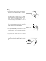
Set-up
• Secure the Triton® T-700 traction unit to the pedestal by
tightening the locking knobs at the middle top and bottom
of the unit.
• Check the voltage rating on the serial plate located on the
back of the unit. Plug the unit into a 120 volt or 220/240
volt AC outlet as required. DO NOT attempt to use direct
current. Follow the procedures indicated in the
precautionary instructions. DO NOT attempt to use the
unit if it is not properly grounded.
• If you’re using a Triton® TRE-24 traction table with your
T-700, plug the power cord into the electrical service
outlet located on the base of the table. Then make sure
the table is properly plugged in and grounded.
• WITH THE POWER TURNED OFF, push the rope release
lever and pull out sufficient rope to connect the “S” hook
to the patient harness. Then take up the slack in the rope.
• Always make certain that the power cord is properly
plugged into the unit.
• The patient switch must be plugged in for the unit to
operate.The control must be given to the patient. Instruct
the patient that pressing the red button will stop the traction.
7
Operation of Model T-700
Step 1: Connect power cord to unit and plug the cord into the appropriate receptacle.
Step 2: Plug patient control switch into front of unit.
Step 3: Attach cervical head halter or the 7040 Cervical Traction or pelvic belt and thoracic restraint to
the patient before proceeding with the traction setup. Make sure that the patient is comfortable
with the fit of the appliance.
Step 4: Pushing the rope release lever on the top of the unit, withdraw ample traction cord to attach
the “S” hook directly to the appliance or to the spreader bar.
Step 5: Holding the rope to prevent jerking, push the release lever again to take up all the slack in the
rope.
Step 6: Give the Patient Switch Cord to the patient. Instruct the patient that pressing the red button will
stop the traction cycle (very important operation precaution procedure).
Step 7: Depress the green power switch. It will light up when the power is on.
Step 8: Select the traction mode to be used. A yellow light will appear for intermittent traction, a red
light for static traction.
Step 9: Select the maximum poundage to be given during traction treatment.
Note: If the maximum poundage selected is above 40 lbs. (18 kgs), the lumbar range lights and
an audible alarm sounds repeatedly. This alarm can be terminated by depressing the red
cervical/lumbar button.
Step 10: When a minimum poundage is desired, select a poundage level below your maximum pounds
Note: If minimum poundage exceeds maximum poundage, an audible alarm will sound repeatedly
and a red light will appear indicating minimum has exceeded the maximum.This situation can be
corrected by simply lowering the minimum below the maximum.
Step 11: Select hold time from 0 to 60 seconds.
Step 12: Select rest time from 0 to 60 seconds.
Note: Your Triton® T-700 is now ready to perform the traction mode and sequence that you have
programmed.
Step 13: Turn the timer switch all the way around clockwise and then back to the desired treatment time
and the machine will automatically begin to pull.
Step 14: Watch the patient and unit for the first three or four cycles and re-adjust the garments if
necessary.
Step 15: Ask the patient to depress the patient control switch so he/she can become familiar with
it and have the security of knowing the treatment can be stopped at any point of discomfort.
When the patient switch has been pushed, rotate the treatment timer off and back on to reset
alarm. Unless this sequence is followed correctly, the machine will not function.
Step 16: The Triton® T-700 will automatically stop at the end of the treatment time and the machine will
return to zero pounds of pull.
Step 17: Caution: Federal law limits this device to the use by or on the order of a physician or licensed
practitioner.
8
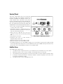
Control Panel
The Triton® T-700. traction unit is an economical
system with many of the features contained in
the MP-1. Equipped with dial-type controls, the
T-700 features both intermittent and static
traction. Intermittent traction can be administered
with a pre-selected minimum pounds of traction
pull. The T-700 is built with Triton high quality and
solid performance in mind with the following features:
• Two modes of treatment available, intermittent
or static, with selector switch.
• Intermittent traction is administered with a
pre-selected minimum pounds of traction pull
with the minimum pounds dial.
• Select from 0 to 200 lbs. (0 to 91 kg on
request) of traction with the maximum pounds
dial.
• Illuminated on-off switch.
The Triton® T-700 Control Panel
• Treatment time from 1 to 60 minutes is
programmed by selector dial.
• Hold time selection is from 0 to 60 seconds.
• Rest time selection is from 0 to 60 seconds.
• A red LED illuminates if more than 40 lbs. (18 kg) is set on max traction and unit will not pull. Pressing
the Cerv/Lumbar switch will put the unit in Lumbar Mode where up to 200 lbs. (91 kg) max traction may
be selected. The Cerv/Lumbar button flashes in the Lumbar Mode.
Audible Alarm
The audible alarm signals when:
1.
2.
3.
4.
5.
The patient switch is depressed. Turn cycle treatment timer off and back on to reset alarm.
Maximum traction is set in excess of 40 lbs., and lumbar mode is not selected.
The minimum pounds setting has been set in an amount that exceeds the maximum pounds setting.
A change in traction pull has been created by conditions outside the operation of the unit, such
as a shift in the patient’s weight.
The patient switch cord is not plugged into unit.
9
Technical Specifications
Main Supply:
Frequency Range:
Main Fuse(s):
Treatment Time:
Hold Rest Times:
Traction Range:
Class/Type:
T-700 Dimensions:
T-700 Weight:
2A/120V (1A/220-240V)
50/60Hz
2A Slo-Blo (1A/250V Anti-Surge)
1 - 60 Minutes
0 - 60 Seconds
0 - 200 lbs. (91 kg)
1B (According to IEC 601-1)
13 1/2” x 12 3/4” x 9 3/4”(34.3 cm x 32.4 cm x 24.8 cm)
34 lbs., 5 oz (15.6 kg)
Danger: Risk of explosion if used in the presence of flammable anesthetics.
10
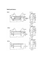
Table Specifications
11
Calibration
All adjustments must be made by a qualified person using proper equipment.
Equipment Needed
•
•
•
•
Strain gauge and meter or dynamometer capable of indicating 0 - 200 lbs. with resolution of 0.5 lbs.
10K potentiometer to substitute for transducer.
Stopwatch
1lb. (1/2 kg) and 1/2 lb. (1/4 kg) weights.
Calibration
1.0 Anti-Reverse Switch Adjustment
1.1
1.2
1.3
1.4
1.5
Verify power cord and patient cord are attached. Plug power cord into power source.
With power OFF, actuate rope release and pull out all the rope.
With power ON, pull gently on rope.
Adjust actuator arm of the anti-reverse switch by bending it until firm pressure on the
rope will shut off the motor.
With power OFF, rewind rope, being careful to keep pressure on rope when released.
2.0 Up Limit Switch Adjustment:
2.1
2.2
2.3
2.4
2.5
2.6
2.7
2.8
2.9
Connect rope/hook to strain gauge or dynamometer.
Turn R28 fully clockwise.
Remove the transducer connection and connect the 10K pot in place of the transducer.
With power ON, set Treatment Timer for 15 minutes in Static mode.
Adjust 10K pot to run motor down.
Turn up limit adjustment screw fully clockwise. It is at the top of the machine.
Turn 10K pot to run motor up.
Monitor strain gauge/dynamometer and adjust up limit screw counterclockwise to trip at 220
lbs. (U.S.) or 240 lbs. (109 kg/Export) + 5 lbs. The trip point will sound an audible alarm and
the motor will run down. Turn power OFF and ON, and then turn 10K pot to run motor down
and then up to recheck trip point.
Turn power OFF, unplug 10K pot and reconnect transducer.
3.0 Open Transducer Protection Circuit Adjustment:
3.1
3.2
3.3
3.4
3.5
Actuate rope release and obtain slack in the rope.
Turn Treatment Timer to 0 and press power ON.
Measure voltage on IC6 pin 2, then adjust R28 to obtain voltage at IC6 pin (3) 100 mv
higher than pin (2).
Verify IC6 pin (1) is high (=11v)
Turn power OFF.
12
4.0 Zero Adjustment (Rope must be slack):
4.1
4.2
4.3
4.4
4.5
4.6
4.7
4.8
4.9
Set Treatment Timer to 15, Max lbs. to 200 (91 kg), Min. to 0 and Mode to Static.
Turn power ON and push Lumbar switch.
Adjust R7 until strain gauge/dynamometer reads 200 lbs. (U.S.) or 220.5 lbs. (91 or 100
kg/Export).
Turn Treatment Timer to 0 and allow unit to release rope tension until the rope is slack.
Set Treatment Timer to 15, Max lbs. to 60 (27 kg), Min. fully counterclockwise, Hold to
10, Rest to 30 and Mode to Intermittent.
Turn power ON. When the machine reaches Rest time, strain gauge/dynamometer
minimum should read 2.5 to 3.1 lbs. (1.13 kg to 1.41 kg). Adjust R3 if needed and allow
T-700 to run up and return to Rest to verify adjustment.Turn Timer OFF.
Pull rope out for slack rope and set trimmer “VR-1” on bottom of the digital read-out for
an indication of “000” to “001.”
Set Treatment Timer to 15, Max lbs. to 30 (14 kg), Min. fully counterclockwise, Hold to
10, Rest to 30 and Mode to Intermittent.
Turn power ON. When the machine is in Rest time, verify panel meter is less than .005
lb. (.0023 kg), and that the Rest time LED is ON. If not, repeat steps 4.5 through 4.9.
5.0 Open Transducer Test:
5.1
5.2
5.3
5.4
Set Treatment Timer to 15, Max lbs. to 30 (14 kg), Min. to 0 and Mode to Static.
Turn power ON and unit will run up and stop.
Unplug transducer and unit will alarm and run down.
Plug in transducer and alarm will stop and the machine will resume normal operation.
6.0 Motor Interlock Test:
6.1
6.2
6.3
6.4
6.5
Turn power ON and activate timer.
Remove patient cord and alarm will continuously sound at a 1 second on,1 second off rate.
Verify that tension on rope does not cause motor to run up.
Insert patient cord.
The alarm should continue until power is turned OFF.
7.0 Patient Switch Test:
7.1
7.2
7.3
Set Treatment Timer to 15, Max lbs. to 30 (14 kg), Min. to 0 and Mode to Static.
Turn power ON and activate timer.
Push and release the patient switch. The alarm will sound and (120 V) the unit will run
to slack rope or (220 V) the unit will brake until timer is reset.
8.0 Lumbar Alarm Test:
8.1
8.2
8.3
Set Treatment Timer to 15, Max lbs. to 50 (23 kg), Min. to 0 and Mode to Static.
Turn power ON and the alarm will sound, the Lumbar will flash rapidly and the unit will
not start.
Depress Lumbar switch and the alarm will stop, Lumbar lamp will flash slowly and the
unit will start.
13
9.0 Minimum Set Above Maximum Test:
9.1
9.2
9.3
10.0
Static Mode (Span) Adjustment:
10.1
10.2
10.3
10.4
10.5
11.0
Set Treatment Timer to 15, Max lbs. to 10 (5 kg), Min. to 0 and Mode to S.
Turn power ON and adjust minimum to 15 lbs. (6.8 kg).
Verify that Min / Max LED and Alarm Sound are ON.
Set Treatment Timer to 15, Max lbs. Fully Clockwise, Min. to 100 (45 kg),Hold to 0, Rest
to 10 and Mode to Static.
Turn power ON and push Lumbar switch.
After unit runs up, adjust R7 until strain gauge/dynamometer reads 200 lbs. or
220.5 lbs. + 5%, (91 kgs or 100 kgs + 5%/Export) making sure to only adjust from an
increasing pull (i.e.: raising from lower poundage (kg). If force is exceeded, cycle unit
down and repeat this step).
Adjust trimmer “VR2” (upper trimmer) on the digital readout for an indication of 199 lbs.
(91 kg).
Set Hold to 10 and Mode to Intermittent. Allow unit to cycle and verify force, while
checking to make sure readout remains correct.
Hold and Reset Time Adjustment/ Treatment Timer Test:
11.1
11.2
11.3
Set Treatment Timer to 30, Max lbs. to 50 (23 kg), Min. to 0, Hold to 10, Rest to 10 and
Mode to Intermittent.
Turn power ON and push Lumbar switch.
When unit runs to 50 lbs. (23 kg), adjust R54 until the Hold LED is ON as follows, at the
respective knob positions:
10 sec. + 1 sec.
11.4
11.5
10 sec. + 1 sec.
11.6
12.0
60 sec. + 4 sec.
30 sec. + 2 sec.
60 sec. + 4 sec.
Set Treatment Timer down to less than 5 minutes and allow to time out. Verify treatment
stops and bell sounds.
Tension Knob Calibration:
12.1
12.2
12.3
12.4
13.0
30 sec. + 2 sec.
Set Hold to 0. With Hold LED OFF, unit runs to 0 lbs. and Rest LED is ON.
Adjust R56 for the Rest LED times as follows, at the respective knob positions:
Set Treatment Timer to 60, Max lbs. to 0, Min. to 0 and Mode to Static.
Starting at 20, adjust Max knob in 10 lb. (5 kg) increments and verify panel digital
readout and strain gage/dynamometer are within +5% of the knob setting or 5 lbs.
(whichever is greater). Adjust knob positions as required. If the desired reading is
exceeded, return to previous pound step,then continue.
Set Max. lb. to 200 (91 kg), Hold to 10, Rest to 10 and Mode to Intermittent.
Starting at 190 lbs. (86 kg), adjust Min. knob in 10 lb (5 kg) decreasing increments and
verify panel digital readout is within +5% of the knob setting or 5 lbs. (whichever is
greater). Adjust knob positions as required. If the desired reading is exceeded, return to
previous pound step, then continue.
Down Limit Switch Adjustment and Check:
13.1
13.2
13.3
13.4
13.5
Mount the unit vertically and turn power ON.
Attach 1 lb. (1/2 kg) weight to rope.
Adjust down limit switch by gently bending the actuator arm until motor stops.
Verify that adding 1/2 lb. (1/4 kg) weight does not cause motor to run.
Install covers on unit.
14
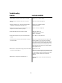
Troubleshooting
SYMPTOM
CAUSE AND/OR REMEDY
1. When machine is turned on, power lamp does not light.
1. Replace fuse F1. Replace Lamp PL1.
2. Motor continues to run down when there is no pull on
the rope.
2. Down limit switch needs adjusting
3. When the treatment time is activated, intermittent alarm
sounds but no alarm lights on front panel are lit.
3. Patient cord is unplugged or broken.
Transducer defective.
4. With the minimum pounds set full counterclockwise, “rest”
lamp does not come on at end of a pull cycle.
4. Zero Pot R3 needs to be adjusted.
5. Lumbar mode lamp does not light when selected.
5. Lamp PL2 is burned out.
Treatment timer is not activated
Alarm is not activated
6. Lumbar alarm lamp does not go out when lumbar mode is
selected.
6. RY3 is bad; S-2 is bad; broken wire.
7. External gear train makes noise when machine is releasing
pull at low pounds.
7. Gear mesh is too tight (Proper gear mesh adjust: With
machine turned off, loosen lock nut on mesh-adjust
screw. Observe clearance between drive gear and idler
gear. Turn mesh-adjust screw counterclockwise for zero
clearance between teeth of drive and idler gears. Then
turn mesh-adjust screw clockwise one and one-quarter
turns.(Tighten lock nut.)
8. Motor does not run down when rope is pulled, with machine
on and power cord plugged in.
8. Replace fuse F1 or F2.
Down limit switch needs adjustment or replacement. The
Anti-Reverse Switch is bad, or possibly the ARS actuator
is stuck, holding the ARS open. Replace the ARS or ARS
actuator as required. Check motor and motor-run
capacitor.
9. Motor does not run up when commanded to do so.
9. Check operation of relays. Check motor and motor-run
capacitor.
15
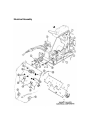
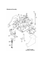
Electrical Assembly
16
Electrical Components Parts List
Item
1
2A
2B
3A
3B
4A/5A
4B/5B
6
7
8A
8B
9
10A
10B
11A
11B
12A
12B
13
14
15
16
17
18
19
20
21
22
23
24
Part No.
73107
73117
67965
60335
79292
60337
79293
70355
71516
70147
70745
70286
60900
60910
71534
71538
70316
70316
73540
73110
70737
74600
71525
72685
71518
72011
71899
72010
72453
21284
Description
Qty.
PC Board Triton® T-700 B1 Assembly
PC Board TX7M-B2 Assembly*
PC Board T-700 Power & Relay Assembly**
Capacitor 6 Microfarad 250 V*
Capacitor 1.5 Microfarad 440 VAC**
Resistor 500 OHM 25 Watt*
Resistor 2000 OHM 25 Watt**
Switch Micro 11SM1-H58
Solenoid
Transformer Signal 241-6-24*
Transformer Signal DP241-6-24**
Connector AC Input Potter 615G6
Fuse Carrier 1/4 x 1-1/4 *
Fuse Carrier 5mm x 20mm **
Fuse MDA 2 Amp 250V Slo-Blo*
Fuse 1 Amp 250V Time Lag**
Fuse Holder*
Fuse Holder**
Connector 1/4” Phone Jack
Patient Cord
Timer 60 Minute Bell
Potentiometer 2.5 mm Clarostat
Switch DPDT
Meter Digital Volt Triton®
Potentiometer 10K Bourns
Switch Alternating Action
Lamp 12V #73
Switch Momentary Action
Cord Set 16 GA 3 Cond Gray*
Cord Set 8’ Euro**
1
1
1
1
1
1
1
2
1
1
1
1
1
2
1
2
1
2
1
1
1
2
1
1
2
1
2
1
1
1
*Indicates items used on 120V units.
**Indicates items used on 220/240V units.
17
Mechanical Assembly
18
Mechanical Components Parts List
Item
Part No.
1
2
3A
3B
4
5
6
7
8
9
10
11
12
13
14
15
16
17
18A
18B
19
20
21
70277
73154
66920
66921
72336
70311
71934
73147
70336
70369
70697
73155
70337
73160
70237
73163
70355
73130
72831
66793
76490
72735
73156
Description
Qty.
Clamp Striker
Clamp Traction Machine Hold Down
Motor Brother 120V*
Motor Brother 220V 50 Hz**
Gear Drive 20 Tooth
Rope Drum Mechanical Traction
Bearing Nice 1616DC
Spring Rope Return Assembly
Knob Clamp
Pulley AN210-3A
Rope Triton® #8 x 68”
Rope Hook
Knob Rope Release
Shaft Rope Drum with Gear
Idler Bearing
Idler Gear
Switch Micro 11SM1-H58
Cradle Casting
Transducer Linear Potentiometer (10K)*
Transducer Bourns **
Spring Transducer Reaction 1.75”
Bolt Shoulder 3/8 x 3 3/4 Special
Clamp Screw
*Indicates items used on 120V units.
1
1
1
1
1
1
2
1
1
3
1
1
1
1
1
1
1
1
1
1
2
2
1
**Indicates items used on 220/240V units.
19
Triton® Tables
The full line of Triton sturdy traction tables completes the
comprehensive Triton Traction System. No other traction
table matches Triton’s combination of strength, comfort and
convenience.
The fully adjustable TRE-24 model is equipped with electric
“Hi-Low” variable height control from 22 to 38 inches. This
feature brings the table to stretcher or wheelchair level for
easy side transfer, eliminating awkward patient lifting.
Adjustable head and lumbar sections can be raised and
lowered, increasing treatment applications. And the TRE-24
traction unit pedestal tilts downward as much as 45 degrees
for administering cervical traction.
Triton also makes two fixed height traction tables. The TRF-22
is a moveable two section, 31” fixed height model that offers
both comfort and economy. The TRF-24 is a four section, 31”
fixed height table with adjustable head and lumbar sections
for greater versatility.
The Triton® Traction System
All Triton traction tables are upholstered in high quality, flame resistant vinyl for easy care and durability.
Five colors are available to match any office decor. Triton’s sturdy design and rugged construction ensure
years of comfort and stability.
Triton® Tables
Fully adjustable head and lower sections tilt
up and down for all common
treatment positions
Traction unit pedestal tilts downward (up to
45°) for administering cervical traction.
Lower sections separate on ball bearing
mounts for use in lumbar traction. Sections
can be locked in place during other treatments. Reduces patient discomfort while
increasing quality of treatment.
Seven position, 180° turret locks into place,
traction unit pedestal rotates for complete
patient accessibility providing comfort and
convenience for both patient and therapist.
20
More Trusted Products from Chattanooga Group, Inc.
Achiever™
Supports
Adapta®
Treatment Tables
A.E.R.® Boot
Auto Edema Reduction Boot
AirMedex™
Alternating Pressure Mattress
boo-boo pac™
Child Size Bear-Shaped Cold Pack
Cambion™
Shock Dampening Foot Care Products
Carpal-Trac™
Carpal Traction Accessory
®
ColPaC
Measurement Instruments
Dynamometers, Goniometers, etc.
Myossage®
Massage Lotion
Nylatex®
Elastic Wraps
OptiFlex®
Continuous Passive Motion
Para-Care®
Paraffin Wax Unit
Pillow Perfect™
Cervical Pillow Line
Pivotal Therapy System™
Orthotics for the Spine
ProPower Pillow™
Power Massage Pillow
Chilling Units and Reusable Cold Therapy PresSsion®
Products
Intermittent Compression
Conductor™ Gel
Pron Pillo ®
Highly Conductive Ultrasound Gel
Positioning Pillow
Contracture Products
Contracture Management Orthotic
Products
CTS™
Carpal Tunnel Stretching Device
Dura-Stick™ Electrodes
Self-Adhesive Electrodes
EMG® Retrainer
Dual Channel Surface EMG
Flexi-Pac™ I and II
Reusable Hot and Cold Compresses
Gel Medex™
Gel Mattress Overlay
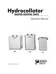
Hydrocollator®
Heating Units and HotPacs™
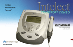
Intelect ® Legend
SPORT-PAC™
Soccer Ball Shaped Cold Pack
Therma-Wrap™
Hot and Cold Compression
Triton®
Treatment and Traction Equipment
TX®
Treatment and Traction Equipment
Vectra™ Series
Ultrasound and Electrotherapy products.
Wellness 1st™
Back Support
Women’s Contour Back Support
Back Support
Ultrasound and Electrotherapy Products
4717 Adams Road • P.O. Box 489
Hixson, TN 37343 U.S.A.
1-423-870-2281
1-800-592-7329 U.S.A.
1-800-361-6661 CANADA
www.chattgroup.com
ISO 9001 CERTIFIED
© 2000 Chattanooga Group, Inc.
72408D