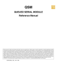
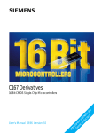
1
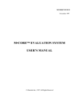
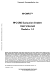
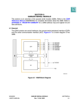
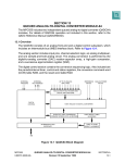
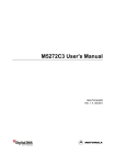
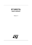
Order this document by MCOREQS/D Rev. 1
Semiconductor Products Sector
Application Note
M•CORE™ EVS Quick Start Guide
1 Introduction
The objective of this guide is to lead the M•CORE developer through the initial stages of the
M•CORE evaluation system (EVS) setup and installation. Detailed EVS information is given in
the M•CORE EVS User’s Manual (MCOREEVSUM/D) which can be found on the world wide
web at: www.motorola.com/mcore. Obtain license keys to install the software before starting
the procedures of this guide. The three major steps in this guide involve 1) setting up the CMB
board, 2) installing the operating software, and 3) running the Quick Start software and
operations.
The EVS is made up of three boards. These boards are illustrated in Figure 1.
CMB board
MAPI Connectors
(Modular Active Probe Interconnect)
IPB board
MAPI Connectors
TIB board
Figure 1 Side View of EVS System Overview (Not to Scale)
2 Configuring the CPU Memory Board (CMB)
This section describes the basic setup and installation of the M•CORE CMB. There are three
EVS modes. These modes are 1) EVS debug, 2) EEPROM program, and 3) user mode. The
EVS debug mode enables the user to download applications to the FSRAM and operate the
EVS system. The EEPROM program mode permits the user to write to the EEPROM of the
CMB. The user mode will run the programs in the EEPROM without any external interface
(excluding the power supply).
The CMB board is roughly illustrated below to show locations which are referred to in the
following text.
SEMICONDUCTOR PRODUCT INFORMATION
Flash Memory
Serial 2
FSRAM
J25
J1
J22
3
2
1
3
2
1
8.
LED
TB1
GND
+5v
J99
M•CORE
Core
J21
••
••
••
••
••
••
MDS • •
MDTACK • •
J24
Serial 1
MAPI
Ring
J2
J4
J3
POWER
Reset
Switch
Figure 2 The CMB Board Overview (Not to Scale)
2.1 Setting Up the CMB Board
The configuration, which is described in this section, places the CMB in EVS debug mode. This
permits the user to activate the SDS Single Step Monitor/Debugger software and download a user
application from the PC.
2.1.1 RS-232 Connection from PC to the CMB
Attach the ten-pin socket for the RS-232 miniature jack cable to socket J25 (UART2) on the CMB.
Next, attach this cable to the RS-232 port on the PC. The CMB side of the cable is keyed to fit only
one way.
2.1.2 Power Supply
Use connector TB1 to connect a user-supplied power supply to the CMB. Contact 1 is VDD (+5
volts) (red lever). Contact 2 is ground (black lever). Use 20 or 22 AWG wire for power connections.
For each wire, trim back the insulation 1/4 in. (.635 cm), lift the appropriate lever of TB1 to release
tension on the contacts, then insert the bare wire into TB1 and close the lever.
2.2 CMB Jumper Header Settings
Place a jumper on pins 1 and 2 of jumper J22.
M•CORE
2
APPLICATION NOTE
MOTOROLA
For normal operation (which applies to this configuration) place a jumper on pins 1 and 2 of jumper
J99.
NOTE:
If the CMB board is used as a standalone (without the IPB), place a jumper across the MDS (pin
13) and MDTACK (pin 15) signals on jumper J21.
3 Configuring the EVS I/O Peripherals Board (IPB)
The IPB board contains two slave peripheral devices and an interrupt control module. These
devices provide the functionality of standard modules which will be included in differing
configurations of future single-chip M•CORE products.
3.1 Setting Up the IPB
Attach the IPB board under the CMB board at the MAPI ring. Power is supplied to the IPB through
the MAPI ring.
3.2 IPB Jumper Header Settings
There are no special jumper header settings at this time.
4 Using the EVS Target Interface Board (TIB)
Attach the target interface board under the IPB board at the MAPI ring with the headers and
bread-board extending beyond the first two boards. These header sockets provide access to the
ports and interrupt I/O for the IPB board.
NOTE:
The target interface board is not used in the Quick Start manual.
5 Software Installation
NOTE:
The software installation steps are intended to supplement the instructions that come with the
software.
5.1 SDS Single Step Monitor/Debugger
5.1.1 Obtain SDS License
To obtain the SDS license key, send email to: [email protected]. The message should request
“MCORE EVAL ONE LICENSE,” and include the name of the requestor, company name, address,
contact name to ship to, valid email address, phone number, and fax number. For SDS help, call
(630) 368-0400, fax (630) 990-8584, or access www:[email protected] .
5.1.2 Install SDS Program
To install Single Step, perform the following steps:
1.
Insert CD-ROM into CD drive.
2.
From the file menu or the start button, choose “Run”.
M•CORE
MOTOROLA
APPLICATION NOTE
3
3.
Type E:\SETUP and press <RETURN>. (“E:” is the CD drive name)
4.
Select the full version of SDS (do not select the lite version)
This installs the SDS Single Step Monitor/Debugger.
The debug window opens when the SDS Single Step Debugger first opens.
1.
The File tab is selected. Enter the location and name of the *.elf file to be downloaded.
2.
Select the Connection tab and choose the serial port. Under “details” choose COM1 and
19200 baud.
3.
Select the Processor tab and choose the M•CORE as the target CPU. Set the
“Co-processor” field to “None”.
4.
Select the Options tab. Set the following options with a check mark: 1) “Create symbol
database”, 2) “Load application image”, 3) “Reset target”, 4) “Execute until main during
reset”, and 5) “Break at exit”. Clear the “Require exact symbol names” option.
5.2 Obtain Diab Data License
To obtain the Diab Data license key, send email to: [email protected]. The message should request
“Please send the license key for the Diab Data (Version 4.1a:0) for the Motorola MCORE EVS,” and
include name of the requestor, company name, address, contact name to ship to, valid email
address, phone number, and fax number. If needed (after installation), enter: dctrl -t (in a DOS
window), select SOFTWARE as the floating point option, then select “cross” as the Ramdisk I/O
option. For Diab Data help, call (415) 571-1700, fax (415) 571-9068, access
http://www:[email protected], or email [email protected].
5.3 Install Diab Data C Compiler
1.
With the CD-ROM in the CD drive, select the top directory of the CD_ROM drive as the
current directory. (The installation program must see the directory “dtools” in the current
directory.)
2.
From an MS-DOS prompt window, for MS-DOS Windows 3.x.x enter:
dtools\MSDOS\setup
<RETURN>
for Windows 95 or Windows NT enter:
dtools\WIN32\setup
<RETURN>
for OS/2 enter:
dtools\OS2\setup
<RETURN>
for IRIX enter:
3.
dtools/SGI/setup
<RETURN>
Enter the “installation key” (obtained using the instructions in 5.2 Obtain Diab Data
License), into the program at this time.
4.
At the MS-DOS prompt line, enter: dctrl -t
a.
Select the SOFTWARE floating point option.
b.
Select: “cross - Ramdisk I/O.”
In addition to the standard installation procedures, the following information is useful.
M•CORE
4
APPLICATION NOTE
MOTOROLA
•
•
In the AUTOEXEC.bat file, add an extension to the path command. This extension is:
(Previous path); C:\diab\4.1a\Win32\bin
Verify the version number of Diab with: dcc -VV.
5.4 GNU C Compiler
This software can be downloaded from the web-site at:
http://www.motorola.com/mcore
The detailed installation instruction can be found in the file ./doc/mcoretools.ps.
5.4.1 Installation for Standard Directories
The M•CORE toolset binary is compiled and configured to be installed in the following location,
based on the host:
Host
Location
Linux
/usr/local
Solaris 2.5
/opt/mcore
SunOS 4.1.3
/usr/local
Unpack the tar file in the specified directory. For example, the Linux installation would be performed
with:
cd /usr/local
tar xf the_linux_distribution_file.tar
Adjust the PATH environment relative to the host. For most uses, /usr/local/bin will already be in the
PATH. For Solaris 2.5 users, the directory /opt/mcore/bin will probably need to be added to the
user’s PATH.
5.4.2 Installation for Non-Standard Directories
For installation in an alternate directory, additional steps are required.
1.
Choose the alternate directory. “/wherever” is used for this example.
2.
cd /wherever (Be sure that the distribution_file.tar file is located here.)
3.
tar xf distribution_file
4.
Set the environment variables as described below (replace “wherever” with the chosen
directory name):
Variable
Value
(add to) PATH
/wherever/bin
GCC_EXEC_PREFIX
/wherever/lib/gcc-lib/mcore-elf/SSRL-2.0/
(Note: The trailing slash is required on the GCC_EXEC_PREFIX)
COMPILER_PATH
/wherever/mcore-elf/bin
C_INCLUDE_PATH
/wherever/mcore-elf/include
CPLUS_INCLUDE_PATH
/wherever/mcore-elf/include
M•CORE
MOTOROLA
APPLICATION NOTE
5
5.
Make sure that all of these variables are exported to sub-processes. (The export command
in sh/ksh, and the setenv command in Cshell.)
6.
Add these definitions to either the .profile or .login files so that the compiler is accessible for
future login sessions. The env command reveals the current settings for the system
environment.
7.
Enter env <RETURN>. This reveals the current settings for the system environment.
6 Running the Sample Programs
The following programs are intended to help the user become acquainted with various aspects of
running the M•CORE evaluation system (EVS). The user will move through the three modes (EVS
debug, EEPROM programming, and user modes) which are available on the EVS. The first two
programs utilize the CMB board only. The final operation incorporates both the CMB and IPB
boards and walks the user through the action of accessing individual registers of the IPB modules.
This final operation uses the SDS Single Step Monitor/Debugger to prove functionality of the IPB
modules.
Connect the RS-232 port to the COM1 port of the host computer. If the program sticks, reset the
board.
NOTE:
SDS Lite version will not run the GETNUM program.
6.1 EVS Debug Mode
6.1.1 Introduction of the GETNUM program
Program number 1 (GETNUM) illustrates the use of the EVS debug mode.
The “GETNUM” program provides an example of a C program which 1) calls an assembly level
function, 2) provides an example of keyboard interface while using SDS debug mode, and 3)
includes all of these functions in one C program. The separate LED legs are directly connected to
the bits of the global control register (GCR). Assembler “moves” to this register alter the LED output.
Figure 3 shows which GCR bits are connected to specific LED locations.
1
2
6
7
5
3
4
8
#
= GCR bit number
Figure 3 GCR Bit to LED Relationship
M•CORE
6
APPLICATION NOTE
MOTOROLA
6.1.2 Procedure for GETNUM: (Diab Data Compiler)
1.
NOTE:
Look on the source disk which is supplied with the EVS. Locate the following programs in
the quickstart/getnum directory. These will be compiled together to form the ELF file for
down-loading into the SDS debug/monitor program to the EVS board. These are:
a.
CHARIO.c
b.
CHARIO.h
c.
LED.h
d.
LNK.dia
e.
ASM_MAC.c
f.
GETNUM.c,
g.
GETNUM.bat.
For a GNU C compilation, replace CHARIO.c with PRINTF.c. The object file OUTC.o is supplied
and must be linked with the other *.o files in the link step.
2.
Create a directory on your local PC that is accessible to the Diab Data controller. In a DOS
prompt window, enter:
3.
mkdir getnum <RETURN>.
Place the files located in step 1 into the directory created in step 2.
4.
In a DOS prompt window, enter:
“dcc -VV” <RETURN>
This tells the version number of Diab Data and implies accessibility. If the command is not
found, then check the diab data compiler and the paths to the compiler.
5.
In the DOS window, type “getnum” at the DOS prompt. This runs the GETNUM.bat batch
file which in turn compiles GETNUM.c and produces GETNUM.elf.
6.
Set the CMB board into EVS debug mode. (This is described in 2 Configuring the CPU
Memory Board (CMB).)
7.
Turn on the 5 volt power to the EVS system. (A “P” will appear on the LED display.)
8.
Start the SDS Monitor/Debugger program. In Windows select: START; Programs; Single
Step 7.1 Monitor.
9.
Select the GETNUM.elf file which was generated in step 5 above. Open this file in the debug
window by selecting OPEN. Use the Browser to find your GETNUM.elf.
10.
Click “OK” in the debug window.
11.
When the GETNUM program has been loaded, close the debug window.
12.
Open the COMMAND window in the SDS Single Step Monitor/Debugger. Enter “go
<RETURN>” at the COMMAND window prompt. Go to step 13 (next step).
13.
Choose any hexadecimal number (0-F), enter this number in the COMMAND window and
hit <RETURN>. This number can be observed on the LED of the CMB board for a brief
period. Repeat this step as often as desired.
14.
Finally, enter “q” and <RETURN>. This quits the GETNUM program. The program can be
reset and run again at this time.
The GETNUM operation is complete at this time.
M•CORE
MOTOROLA
APPLICATION NOTE
7
6.2 Flash Programming Mode
6.2.1 Introduction of the EEPROM Flash Programming Mode
Program 2 (cmbflash.exe) illustrates the use of flash programming mode. In this mode, the EVS
downloads user software into the EEPROMs of the CMB and stores that program. The following
paragraphs of this section describe the procedure.
From an MS-DOS window, use the command “cmbflash filename” to download the software. The
“filename” is the name of the S-record version of the application. This S-record is created by the
Diab Data software.
The “SHOWA” program downloads an S-record into the EEPROM which counts from $0 to $F. The
“SHOWB” program counts from $F to $0. Alternating the downloads of these two programs proves
that the EEPROMs have been reprogrammed.
6.2.2 Procedure for Programming the EEPROM of the CMB
The following steps alternately program the EEPROM of the CMB:
1.
Look on the source disk which is supplied with the EVS. Locate the following programs in
the quickstart/romshow directory. These are compiled together to form the S-record files
for programming the EEPROMs of the EVS. These are:
a.
CHARIO.h
b.
CHARIO.o
c.
SHOWA.c / SHOWB.c
d.
SHOWA.bat / SHOWB.bat
e.
LED.h
f.
ZERO.s
g.
ASM_MAC.h
h.
ROMA.lnk (ROMA)
i.
ROMB.lnk (ROMB)
j.
CMBFLASH.exe (CMBFLASH)
2.
Create a directory on your local PC. In a DOS window, enter:
3.
mkdir romshow <RETURN>
Place the programs located in step 1 into the directory created in step 2.
4.
In a DOS window of your local ROMSHOW directory, type:
>showa <RETURN>
on the command line. This runs the SHOWA.bat batch file and produces the S-record file,
“SHOWA.REC”, for downloading to the CMB. (Other files are also generated which can be
ignored.)
5.
On the DOS command line type:
>showb <RETURN>
in order to produce the S-record file, “SHOWB.REC”.
M•CORE
8
APPLICATION NOTE
MOTOROLA
6.
7.
To set the CMB board for this mode,
a.
Place the RS-232 connector into UART1 (J24, closest to the reset switch).
b.
Remove the jumper on J22.
Alternate the programming of the EEPROM by downloading SHOWA.REC followed by
downloading SHOWB.REC as follows:
a.
Remove power from the CMB board.
b.
In a DOS window in the ROMSHOW directory, type:
c.
d.
>cmbflash showa.rec <RETURN>
When instructed in the CMBFLASH GUI window, turn on the power to the CMB. Do not
turn on the power to the CMB until the CMBFLASH window says that it is ready to
download the data packets. (Toggle RESET if the download does not start
automatically.)
The CMBFLASH GUI window shows the results of EEPROM loading. When this
program is finished, the user will be instructed to remove the UART connection and
reboot the CMB.
Unhook the RS-232 cable from UART1.
e.
Reboot the CMB board. This reboot can be accomplished with either a RESET or by
removing and adding power to the board.
f.
Exit the CMBFLASH program on the PC by closing the GUI window.
When the power returns to the CMB, the user should see the LED on the CMB count upwards from
$0 to $F. This cycles three times. A reset of the CMB starts the sequence again.
Repeat steps “6” through “7f” except use the command:
>cmbflash showb.rec <RETURN>
for step “7b”, on the DOS command line.
When the LED counts downward from $F to $0, the user has reprogrammed the EEPROM and has
visual proof that this has been accomplished. This completes the Flash programming mode
procedure.
6.3 User Application Mode
This mode was accomplished in steps 7d and 7e in the programming procedure above. To
configure any time for this mode, remove the RS-232 cable from the CMB. Make sure that the
jumper on J22 is not attached. Apply power to the board and check the LED output to see if the last
program entered into the EEPROM has been downloaded into the FSRAM and is running on the
M•CORE.
7 Accessing Peripheral Modules
7.1 Quick Start Access of Specific Registers
The modules of the IPB board are accessed through the SDS Single Step Monitor/Debugger
program in EVS debug mode. Specific registers of each module will be 1) read, 2) written to
M•CORE
MOTOROLA
APPLICATION NOTE
9
configure and prove access, and 3) read again to confirm that the module registers were updated.
These example registers have been selected due to READ/WRITE capability and are not intended
to be configuration settings.
The procedure is as follows:
1.
Remove power from the EVS board.
2.
If not connected: Attach the IPB board beneath the CMB board. Line up the MAPI rings and
the marker triangle and carefully push the boards together at the MAPI ring. J1 should align
with J1 of the other board. The same goes for J2, J3, and J4.
3.
Configure the EVS as described in 2 Configuring the CPU Memory Board (CMB) and 3
Configuring the EVS I/O Peripherals Board (IPB).
4.
Add 5 volt power to the EVS.
5.
Start the SDS Single Step Monitor/Debugger program.
6.
In the initial debug mode window, put an “X” (check) in the box for debug without a program.
Click “OK”.
7.
Close the debug window. Click “close”.
8.
Open the command window. This allows access directly to the module address locations.
9.
10.
11.
In the command window enter:
a.
read -w 0x1203208 <RETURN>.
b.
Confirm that the return value is 0x0000. This is the first set of numbers displayed. This
reads the port A data direction register (DDRQA) of the QADC module which should be
set to 0x0000 at reset.
In the command window enter:
a.
Write 0x1203208 <RETURN>. This enters write mode for the DDRQA register.
b.
Enter 0xFFFF <RETURN>.
c.
Enter a period (.) and <RETURN> to end the write.
d.
Enter read 0x1203208 <RETURN>. This confirms an expected result of 0xFF00.
Repeat steps 9 through 10d with the registers listed in the table below. This confirms
connectivity to each module of the slave peripherals.
Table 1 Module Registers to Test Read/Write
Register
Address
Peripheral
Device Number
QADC Data Direction Register (DDRQA)
0x1203208
QSM Interrupt Level/Vector Register (QILR/QIVR)
0x1203C04
Peripheral Device Register Name
NOTE:
Value at
Reset
Value to
Write
Value After
Write
1
0x0000
0xFFFF
0xFF00
1
0x000F
0x3F01
0x3F01
0x0000
0xFFFF
CTM4 Pulse-Width Register (PWM5B)
0x120342C
1
0xXXXX
0x0000
0xFFFF
TouCAN Interrupt Mask (IMASK)
0x12030A2
1
0x0000
0xFFFF
0xFFFF
QADC Data Direction Register (DDRQA)
0x1205208
2
0x0000
0xFFFF
0xFF00
QSM Interrupt Level/Vector Register (QILR/QIVR)
0x1205C04
2
0x000F
0x3F01
0x3F01
0x0000
0xFFFF
0xFFFF
CTM4 Pulse-Width Register (PWM5B)
0x120542C
2
0xXXXX
0x0000
0xFFFF
TouCAN Interrupt Mask (IMASK)
0x12050A2
2
0x0000
0xFFFF
The CTM4 PWM5B register must first be initialized to 0x0000 to proceed. For this reason, two write
and read procedures are listed for these registers in Table 1.
M•CORE
10
APPLICATION NOTE
MOTOROLA
The act of reading, writing, and reading each of these registers proves connectivity to one register
of each of the modules found on each of the peripheral devices on the IPB board.
This completes the Quick Start procedures.
7.2 Access of All Peripheral Device Registers
The registers of the peripheral devices can be accessed with the following key:
0x120XZZZ
Where 0x120 is the base address for all IPB accesses.
Where X = 3 or 5 for the first or second peripheral device, respectively.
Where ZZZ = The specific register address in the lower twelve bits.
8 Description of Software Programs
The following programs are used in the Quick Start activities.
Table 2 Program Descriptions
Program Name
SHOWA.c
SHOWB.c
LED.h
Description of Program Function
These are the basic C programs to be compiled for the EEPROM programs. SHOWA.c counts up
from $0 to $F, while SHOWB.c counts down from $F to $0.
LED.h defines the LED patterns for the function calls.
ASM_MAC.h
This represents the assembly routine which is called by the C program. While this is very simple, this
call serves as an example of how to enter more complex assembly routines.
CHARIO.o
When using Diab Data C compiler, this program has character input/output and interrupt functions for
the M•CORE EVS. This is not necessary for the EEPROM download. However, CHARIO.o is
necessary for producing a proper interrupt in the SDS download (EVS debug mode).
CHARIO.h
When using Diab Data C compiler, this provides support for the CHARIO.o program. Keep these
programs together.
CHARIO.c
Provides the I/O character support for the GETNUM procedure.
SHOWA.rec
SHOWB.rec
These are the S-record files which result from using the SHOWA.bat and SHOWB.bat. These files are
used in the CMBFLASH program to program the EEPROMs of the CMB.
SHOWA.bat
SHOWB.bat
These are the batch files to compile and link the C programs. S-records are also created and written to
SHOWA.rec and SHOWB.rec respectively.
ROMA.lnk
ROMB.lnk
ZERO.s
CMBFLASH.exe
LNK.dia
These files link the C programs respectively. They set the ROM, RAM, and stack addresses for
downloading to the EEPROMS.
This file provides the information for interrupt space which overrides the CRT0.o file when properly
included into a link file. (As is done with ROMA.lnk.)
This executable program prepares S-records into packets for the M•CORE EVS EEPROM. Then the
program downloads these packets and programs the EEPROM. This program provides protection
against overwriting the SDS program in the EEPROM.
This program properly links the files of the GETNUM procedure.
ASM_MAC.c
This program provides the same function as ASM_MAC.h.
GETNUM.bat
This is the batch file to produce the GETNUM.elf file for the SDS debug/monitor.
GETNUM.c
OUTC.c
PRINTF.c
This is a C program which illustrates keyboard interaction to the M•CORE EVS LED in EVS debug
mode. GETNUM.c illustrates the call of an assembler routine in a C program for the M•CORE. The
user can expand on this program as desired.
When using GNU C compiler, this program handles character I/O functions. OUT.c is used with
PRINTF.c. This must be compiled on Diab Data C since GNU does not currently support the PRINTF
functions.
When using GNU C compiler, PRINTF.c handles I/O and interrupt functions with OUT.c
M•CORE
MOTOROLA
APPLICATION NOTE
11
Motorola reserves the right to make changes without further notice to any products herein. Motorola makes no warranty, representation or guarantee regarding the suitability of its
products for any particular purpose, nor does Motorola assume any liability arising out of the application or use of any product or circuit, and specifically disclaims any and all liability,
including without limitation consequential or incidental damages. "Typical" parameters which may be provided in Motorola data sheets and/or specifications can and do vary in different
applications and actual performance may vary over time. All operating parameters, including "Typicals" must be validated for each customer application by customer’s technical experts.
Motorola does not convey any license under its patent rights nor the rights of others. Motorola products are not designed, intended, or authorized for use as components in systems
intended for surgical implant into the body, or other applications intended to support or sustain life, or for any other application in which the failure of the Motorola product could create a
situation where personal injury or death may occur. Should Buyer purchase or use Motorola products for any such unintended or unauthorized application, Buyer shall indemnify and hold
Motorola and its officers, employees, subsidiaries, affiliates, and distributors harmless against all claims, costs, damages, and expenses, and reasonable attorney fees arising out of,
directly or indirectly, any claim of personal injury or death associated with such unintended or unauthorized use, even if such claim alleges that Motorola was negligent regarding the
design or manufacture of the part. Motorola and
are registered trademarks of Motorola, Inc. Motorola, Inc. is an Equal Opportunity/Affirmative Action Employer.
How to reach us:
USA/EUROPE/Locations Not Listed: Motorola Literature Distribution, P.O. Box 5405, Denver, Colorado 80217, 1-800-441-2447 or
1-303-675-2140. Customer Focus Center, 1-800-521-6274
JAPAN: Nippon Motorola Ltd.: SPD, Strategic Planning Office, 141, 4-32-1 Nishi-Gotanda, Shinagawa-ku, Tokyo, Japan. 03-5487-8488
ASIA/PACIFIC: Motorola Semiconductors H.K. Ltd., 8B Tai Ping Industrial Park, 51 Ting Kok Road, Tai Po, N.T., Hong Kong. 852-26629298
Mfax™, Motorola Fax Back System: [email protected]; http://sps.motorola.com/mfax/;
TOUCHTONE, 1-602-244-6609; US and Canada ONLY, 1-800-774-1848
HOME PAGE: http://motorola.com/sps/
Mfax is a trademark of Motorola, Inc.
© Motorola, Inc., 1998
MCOREQS/D Rev. 1